1
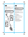
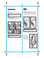
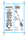
Operator’s Manual
12 Amp
Electric
Lawn Edger
Model No.
172.79183
CAUTION:
Read, understand and follow all Safety
Rules and Operating Instructions in this
Manual before using this product.
Sears Brands Management Corporation,
Hoffman Estates, IL 60179 U.S.A.
www.craftsman.com
• WARRANTY
• SAFETY
• ASSEMBLY
• OPERATION
• MAINTENANCE
• PARTS LIST
SAFETY SYMBOLS
TABLE OF CONTENTS
Warranty……………………………..........................................……………..Page 2
Safety Symbols……………………..........................................……………..Page 3
Safety Instructions……………………..........................................……….....Pages 4 - 9
Unpacking..……………………………...........................………………….....Page 10
Description………………………………..........................................………..Pages 11 - 12
Assembly and Adjustments………………………………..............................Pages 13 - 16
Operation...................………………………..........................................…...Pages 17 - 22
Maintenance..........……………………..........................................………....Pages 23 - 24
Parts List.......……………………..........................................…………….....Pages 25 - 27
The purpose of safety symbols is to attract your attention to possible dangers. The
safety symbols, and the explanations with them, deserve your careful attention and
understanding. The symbol warnings DO NOT by themselves eliminate any danger.
The instructions and warnings they give are no substitutes for proper accident
prevention measures.
! WARNING: BE SURE to read and understand all safety instructions in this
manual, including all safety alert symbols such as “DANGER”, “WARNING”
and “CAUTION”, BEFORE using this tool. Failure to follow all instructions listed
below may result in electric shock, fire and/or serious personal injury.
SYMBOL MEANING
!
CRAFTSMAN TWO YEAR FULL WARRANTY
FOR TWO YEARS from the date of purchase, this product is warranted against any
defects in material or workmanship. Defective product will be replaced free of charge.
SAFETY ALERT SYMBOL: Indicates DANGER, WARNING, OR
CAUTION. May be used in conjunction with other symbols or pictographs.
!
DANGER
Failure to obey this safety warning WILL result in death or
serious injury to yourself or to others. Always follow the
safety precautions to reduce the risk of fire, electric shock
and personal injury.
!
WARNING
Failure to obey this safety warning CAN result in death or
serious injury to yourself or to others. Always follow the
safety precautions to reduce the risk of fire, electric shock
and personal injury.
!
CAUTION
Failure to obey this safety warning MAY result in personal
injury to yourself or others or property damage. Always
follow the safety precautions to reduce the risk of fire,
electric shock and personal injury.
For warranty coverage details or to obtain free replacement,
visit the web site: www.craftsman.com
This warranty does not cover the blade, which is an expendable part that can wear
out from normal use within the warranty period.
This warranty is void if this product is ever used while providing commercial services
or if rented to another person.
This warranty gives you specific legal rights, and you may also have other rights
which vary from state to state.
Sears Brands Management Corporation, Hoffman Estates, IL 60179
DAMAGE PREVENTION AND INFORMATION MESSAGES
! WARNING: Some dust created by using lawn and garden power tools
contains chemicals known to the State of California to cause cancer and birth
defects or other reproductive harm.
These inform user of important information and/or instructions that could lead to
equipment or other property damage if not followed. Each message is preceded by the word
“NOTE:” as in the example below:
NOTE: Equipment and/or property damage may result if these instructions
are not followed.
! WARNING: The operation of any edger can result in
foreign objects being thrown into your eyes, which can
result in severe eye damage. Before beginning power tool
operation, ALWAYS wear safety goggles or safety glasses
with side shields and a full-face shield when needed. We
recommend a Wide Vision Safety Mask for use over
eyeglasses or standard safety glasses with side shields,
available at Sears Stores or other Craftsman Outlets.
SAVE THESE INSTRUCTIONS!
READ ALL INSTRUCTIONS!
2
3
SAFETY INSTRUCTIONS
!
SAFETY INSTRUCTIONS cont.
WARNING: if correctly used, this electric Edger is an easy to handle and
efficient tool; if used improperly or without the due precautions it could become a
dangerous tool. For pleasant and safe work, ALWAYS strictly comply with the safety
rules that are contained in this manual.
! WARNING: BE SURE to read and understand all instructions in this manual
before using this electric Edger. Failure to follow all instructions listed below may
result in electric shock, fire and /or serious personal injury.
!
WARNING: To avoid mistakes that could cause serious injury, DO NOT plug
in this tool until the following instructions have been read and understood.
WORK AREA SAFETY
1. ALWAYS avoid dangerous conditions. DO NOT use in wet or damp areas or
expose to rain.
2. DO NOT operate in the presence of flammable liquids, gases, or dust. Electric
tools create sparks which may ignite dust or fumes.
3. ALWAYS keep bystanders and visitors at a safe distance while operating
an Edger. NEVER allow children near the tool. Flying objects can injure anyone
in the area.
4. CHILDPROOF your tools with padlocks and master switches. Lock tools away when
not in use. This Edger is not a toy.
5. DO NOT use the Edger without adequate lighting. ALWAYS make sure that you can
see what you are edging.
6. BEFORE using the Edger, remove any stones, sticks, debris or objects that could
be entangled in or thrown by the Edger.
PERSONAL SAFETY
! WARNING: The operation of any Edger can result in FOREIGN OBJECTS
BEING THROWN, which can result in personal injury or property damage.
ALWAYS use proper safety equipment.
1. KNOW your tool. Read the operator’s manual carefully. Learn the electric Edger’s
applications and limitations, as well as the specific potential hazards related to this tool.
2. STAY ALERT, watch what you are doing and use common sense when operating this tool.
3. DO NOT use tool while tired or under the influence of drugs, alcohol or medication.
A moment of inattention while operating this tool may result in serious personal injury.
4. DRESS properly. Wear rubber gloves and substantial rubber soled footwear when
working outdoors. DO NOT operate lawn and garden tools when barefoot or wearing
open sandals. Wear long pants and long sleeves to protect your legs and arms.
Edgers can pick up objects such as rocks and send them flying at fast speeds.
DO NOT wear loose clothing or jewelry. Keep your hair, clothing, and gloves away
form moving parts. Loose clothing or long hair can be caught in moving parts.
4
PERSONAL SAFETY cont.
5. USE SAFETY EQUIPMENT. Always wear safety goggles or safety glasses with side
shields or full face shield, proper work shoes with rubber non-slip soles, heavy-duty
non-slip rubber gloves and dust mask or respirator and hearing protection. Hard
hat should be used for appropriate conditions.
6. DO NOT overreach. Keep proper footing and balance at all times. Proper footing and
balance enables better control of the tool in unexpected situations.
TOOL USE AND CARE SAFETY
! WARNING: BE SURE to read and understand all instructions before
operating this tool. Failure to follow all instructions listed below may result in
electric shock, fire and/or serious personal injury.
1. DO NOT use the tool if switch does not turn it “On” or “Off”. Any tool that cannot be
controlled with the switch is dangerous and must be repaired.
2. DISCONNECT the plug from the power source before making any adjustments,
changing accessories, or storing the tool. Such preventive safety measures reduce the
risk of starting the tool accidentally.
3. STORE idle tools out of the reach of children and other untrained persons. Children
MUST NOT operate the tool. Tools are dangerous in the hands of untrained users.
4. MAINTAIN tools with care. ALWAYS keep cutting tools clean and in good working order.
5. CHECK for misalignment or binding of moving parts, breakage of parts, and any other
condition that may affect the tool's operation. If damaged, have the tool serviced
before using. Many accidents are caused by poorly maintained tools.
6. USE ONLY cutting blades that are recommended for this Edger. Blades that may be
suitable for one Edger may become hazardous when used on another Edger.
ELECTRICAL SAFETY
! WARNING: Do not permit fingers to touch
the terminals of plug when installing or removing
the extension cord from the plug.
1. Double insulated tools are equipped with a polarized plug
(one blade is wider than the other and will require the use
of a polarized extension cord. The Edger’s plug will fit into a
polarized extension cord only one way. If the plug does not fit
fully into the extension cord, reverse the plug. If the plug still
does not fit, obtain a correct polarized extension cord.
A polarized extension cord will require the use of a polarized
wall outlet. This plug will fit into the polarized wall outlet only
one way. If the plug does not fit ifit fully into the wall outlet,
reverse the plug. If the plug still does not fit, contact a qualified
electrician to install the proper outlet. Do not change or alter
the equipment plug, extension cord receptacle, or extension cord plug in any way.
2. Double insulation eliminates the need for the three-wire grounded power cord and
grounded power supply system. Applicable only to Class II (double-insulated) tools.
This Edger is a double insulated tool.
5
SAFETY INSTRUCTIONS cont.
SAFETY INSTRUCTIONS cont.
ELECTRICAL SAFETY cont.
!
EXTENSION CORDS cont.
WARNING: GFCI (Ground Fault Circuit Interrupter) protection should be
provided on all circuits or outlets to be used for electric lawn and garden power
tools. Receptacles are available having built-in GFCI protection and should be
used for this measure of protection.
!
WARNING: Double insulation DOES NOT take the place of normal safety
precautions when operating this tool.
3. BEFORE plugging in the tool, BE SURE that the outlet voltage supplied is within
the voltage marked on the tool’s data plate. DO NOT use “AC only” rated tools with a DC
power supply.
4. DO NOT expose tools to rain or wet conditions or use electric tools in wet or damp
locations. Water entering an electric tool will increase the risk of electric shock.
5. If operating an electric tool in damp locations is unavoidable, ALWAYS USE a
Ground Fault Circuit Interrupter to supply power to your tool. ALWAYS WEAR
electrician’s rubber gloves and footwear in damp conditions.
! WARNING: Check extension cords before each use. If damaged replace
immediately. Never use tool with a damaged cord since touching the damaged
area could cause electrical shock, resulting in serious injury.
SAFETY SYMBOLS FOR YOUR TOOL
The label on your tool may include the following symbols.
V.......................................................................Volts
A...................................................................... Amps
Hz.................................................................... Hertz
W..................................................................... Watts
min..................................................................Minutes
....................................................................Alternating current
..................................................................Direct current
no ....................................................................No-load speed
....................................................................Class II construction
.../min.............................................................. Revolutions or Strokes per minute
! ....................................................................Indicates danger, warning or caution.
It means attention! Your safety is involved.
6. When operating a power tool outside, ALWAYS use an outdoor extension cord marked
“W-A” or “W”. these cords are rated for outdoor use and reduce the risk of electric shock.
SERVICE SAFETY
8. DO NOT abuse the extension cord. NEVER use the cord to carry the tool by or to
pull the plug from the outlet. Keep cord away from heat, oil, sharp edges or moving parts.
Replace damaged cords immediately. Damaged cords increase the risk of electric shock.
2. Tool service should be performed at a Sears Parts and Repair Center or other
qualified service dealer. Service or maintenance performed by unqualified personnel
could result in a risk of injury.
7. INSPECT tool cords for damage. Have damaged tool cords repaired at a Sears Service
Center. BE SURE to stay constantly aware of the cord location and keep it well away
from the cutting blade.
EXTENSION CORDS
Use a proper extension cord. ONLY use cords listed by Underwriters Laboratories (UL).
Other extension cords can cause a drop in line voltage, resulting in a loss of power
and overheating of tool.
For this tool an AWG (American Wire Gauge) size of a least 14-gauge is recommended
for an extension cord of 25-ft. or less in length. Use 12-gauge for an extension cord
of 50-ft. Extension cords 100-ft. or longer are not recommended.
Remember, a smaller wire gauge size has greater capacity than a larger number
(14-gauge wire has more capacity than 16-gauge wire; 12-gauge wire has more capacity
than 14-gauge). When in doubt use the smaller number.
When operating a power tool outdoors, use an outdoor extension cord marked “W-A” or “W”.
These cords are rated for outdoor use and reduce the risk of electric shock.
! CAUTION: Keep the extension cord clear of the work area. Position the
cord so that it will not get caught on bushes, hedges, tree trunks, lawnmowers
or other obstructions while you are working with the Edger.
6
1. If any part of this Edger is missing or should break, bend, or fail in any way;
or should any electrical component fail to perform properly: SHUT OFF the
power switch and remove the power cord from the Edger and have the missing,
damaged or failed parts replaced BEFORE resuming operation.
3. When servicing a tool, use only identical replacement parts. Follow instructions
in the maintenance section of this manual. Use of unauthorized parts or failure to
follow maintenance instructions may create a risk of electric shock or injury.
SAFETY RULES FOR ELECTRIC EDGERS
1. KNOW your electric Edger. Read operator’s manual carefully. Learn the
applications and limitations, as well as the specific potential hazards related to this tool.
Following this rule will reduce the risk of electric shock, fire or serious injury.
2. DO NOT use the Edger without adequate lighting. ALWAYS make sure that you can
see what you are edging.
3. Use Edger ONLY when grass and weeds are dry.
4. ALWAYS stand to the left of the Handle. Any debris thrown by the Edger would be
coming from the Blade Guard area on the right of the Edger.
5. ALWAYS remove objects such as stones, sticks, and debris from the edging
path that could become entangled in, or thrown by the Edger.
6. To reduce the risk of rebound (ricochet), work going away from any nearby solid object
such as a wall, steps, large stone, tree, etc. Use care when working near solid objects
or into the wind. If necessary, do edging in those areas by hand.
7
SAFETY INSTRUCTIONS cont.
SAFETY INSTRUCTIONS cont.
SAFETY RULES FOR ELECTRIC EDGERS cont.
7. ALWAYS hold the Edger with both hands on the Handle and NEVER reach near or
under the Blade Guard.
8. AVOID accidental starting. DO NOT carry a plugged in Edger with your finger
on the Power Switch Lever.
9. DO NOT carry the Edger by the extension cord or pull the cord to disconnect it from the
receptacle. Keep cord away from heat, oil and sharp edges.
10. DO NOT FORCE the Edger. Do not try to cut more than what the Edger is designed
for. It will do a better job with less chance of injury when used at the rate for which it is
designed.
11. MAINTAIN the Edger with care. ALWAYS inspect the extension cord and replace if damaged.
! WARNING: NEVER reach under the Edger (blade area) until you have
unplugged Edger and the Edger has come to a complete stop.
The Edger’s blade will continue to rotate for a few seconds after it is switched off.
ADDITIONAL RULES FOR SAFE OPERATION
! WARNING: BE SURE to read and understand all instructions. Failure to
follow all instructions listed below may result in electric shock, fire and/or
serious personal injury.
12. KEEP the Handle dry, clean and free of oil and grease. Use a clean cloth when cleaning.
DO NOT use solvents, brake fluids, gasoline, or other petroleum products to clean the
Edger. They can damage plastic parts.
1. ALWAYS wear safety glasses or eye shields when using this Edger.
Everyday eyeglasses have only impact-resistant lenses; they are NOT safety glasses.
14. KEEP Blade Guard in place and in good working order. Keep Guard positioned over blade.
Keep hands and feet away from cutting blade.
3. PROTECT your hearing. Wear appropriate personal hearing protection during use.
Under some conditions noise from this product may contribute to hearing loss.
16. ALWAYS use only the blade provided with this Edger or sold specifically for this
Edger. Use of any other blades may create a hazardous situation.
5. ALWAYS check the tool for damaged parts. Check for misalignment or binding of moving
parts, breakage of parts, and any other condition that may affect the tool’s operation. Before
further use of the tool, a guard or other part that is damaged should be carefully checked to
determine if it will operate properly and perform its intended function. A guard or other part
that is damaged should be properly repaired or replaced at a Sears or other qualified
service dealer.
13. NEVER, for any reason, touch the cutting blade or other moving parts during use.
2. PROTECT your lungs. Wear a face mask, dust mask or respirator if the operation is dusty.
15. ALWAYS store the Edger indoors when not in use. It should be stored in a dry place,
high up or locked in a place that is out of the reach of children.
4. ALL VISITORS AND BYSTANDERS MUST wear the same safety equipment that the
operator of the tool wears.
17. ALWAYS keep ventilation openings clear of debris.
18. KEEP ALL BYSTANDERS AWAY at a safe distance from the work area, especially children.
Make sure that persons and pets are at least 100 feet away.
6.
! WARNING: Some dust particles created by lawn and garden tools
contain chemicals known to cause cancer, birth defects or other reproductive
harm. Some examples of these chemicals are:
• Compounds in fertilizers, herbicides, pesticides, and insecticides.
• Arsenic and chromium from chemically treated lumber.
SAVE THESE INSTRUCTIONS. Refer to them frequently and use them
to instruct others who may use this tool. If someone borrows this tool, make sure
they have these instructions also.
Your risk from these exposures varies, depending upon how often you do this
type of work. To reduce your exposure to these chemicals:
• Work in a well-ventilated area
• Work with approved safety equipment, such as those dust masks
that are specially designed to filter out microscopic particles.
8
9
DESCRIPTION
UNPACKING
1. The Edger comes fully assembled except for the Handle, which is in pieces and connected
by internal wiring, and must be assembled (Fig 1).
2. Included is a bag with the two Knobs and Curved Head Bolts for assembling the Handle.
3. Remove the Edger with Handle, along with bag of Knobs and Bolts, from the carton.
Inspect your Edger.
4. Do not discard box or packing material until all parts are examined.
! WARNING: If any part of the Edger is missing or damaged, do not plug
in the Edger until the damaged part is repaired or replaced.
Fig. 1
Remove Black Plastic Tube
Coating from the piece of wire
between the Handle and the
Upper Tube.
Handle
wire
KNOW YOUR EDGER
NOTE: Before attempting to use this product, familiarize yourself with all
operating features and safety rules.
Your Edger has a precision built electric motor and it should only be connected
to a 120-volt, 60 Hz AC ONLY power supply (normal household current). The Edger
should always be used with a GFCI (Ground Fault Circuit Interrupter) outlet.
DO NOT operate this Edger on direct current (DC). The large voltage drop would cause
a loss of power and the motor would overheat.
If the Edger does not operate when plugged into correct 120-volt, 60 Hz AC ONLY outlet,
check the power supply. The Edger comes with an electric plug and should be plugged into
a proper extension cord.
This Edger has the following features:
1. 2-in-1 function converts Edger to Trencher.
2. 3-position Blade Depth Adjustment with indicator (1”, 1 ¼” & 1 ½”).
3. Powerful 12.0 Amp, 4700 / min (no-load speed) motor for heavy-duty edging
and trenching.
4. Ergonomically designed Handle with comfort grip reduces fatigue and
improves control.
Handle
5. Easy access to 7 ½” blade for cleaning debris.
Black Plastic
Tube Coating
Two Knobs and
Curved Head Bolts
(in plastic bag provided)
Upper
Tube
Upper
Tube
6 2-Position Adjustable Length Handle Shaft.
7. Edge Guide Adjustment Lever raises or lowers Edge Guide.
8. 6-in. Rear Wheels, and Front Wheel with Wheel Height Adjustment.
9. Cut line indicator helps maintain straight, even cuts.
Lower
Tube
10
11
DESCRIPTION cont.
ASSEMBLY & ADJUSTMENTS
ATTACHING THE HANDLE
The handle comes packaged in sections, which are connected together by internal coated
wiring running through the middle of all the handle pieces.
KNOW YOUR EDGER cont. Fig. 2
Power Switch Lever
Handle
1. Carefully remove packing material and plastic wrapping around tool and handle pieces,
being careful to keep pieces connected.
2. Remove the Knobs and Curved Head Bolts from the plastic bag.
3. Remove the black plastic tube coating from the piece of wire between the Handle and
the Upper Tube (Fig. 1). This will enable the bolt to fit through the smaller diameter Handle.
4. Slide the Handle down into the end of the Upper Tube so the holes line up (Fig. 3a).
Carefully insert bolt, being careful to avoid covered wire inside handle shaft (Fig. 3b).
Fasten together by tightening Knob onto Curved Head Bolt.
5. Slide Upper Tube down into Lower Tube so that holes line up. Do not remove the black
plastic tube coating from the wire at this connection.There are two positions available for
adjustment to your preferred height (Fig.4a). NOTE: When you first insert the bolt,
it may be necessary to wiggle it carefully to get it past the coated wire inside the
Tube. Fasten together with second Knob and Curved Head Bolt (Fig.4b).
2-Prong Power Plug
for extension cord
Power
Safety Lock-Off Switch
Fig. 3a
Fig. 3b
Fig. 4a
Fig. 4b
Knobs with
Curved Head Bolts
Extension Cord
Retainer with Hook
Upper Tube
Front View
Cut Line
Indicator
Lower Tube
Motor Air
Vents
Rear
Wheels
Front
Wheel
Edge Guide
Adjustment
Lever
Blade
Guard
Blade
Cutting Depth Knob
with Release Lever
Blade Guard
Release Lever
NOTE: Be sure the wire cable moves smoothly down into the Lower Handle Tube
while assembling.
Edge Guide
Blade
12
Screw to loosen
Blade Guard
!
CAUTION: NEVER use a sharp object to move coated wires out of the way.
13
ASSEMBLY & ADJUSTMENTS cont.
ATTACHING EXTENSION CORD
1. Insert extension cord socket into Edger’s Power Plug (Fig. 5).
2. An Extension Cord Retainer is attached to the Handle to reduce strain on the cord.
To use this feature, simply double the extension cord as shown, about a foot from
the end, and insert it into the end of the Retainer. Place the loop formed by
doubling the cord over the Hook (Fig. 6a). Gently tug on the cord to ensure that it
is firmly situated in the Retainer (Fig. 6b).
3. Keep extension cord clear of operator, unit and any obstacles at all times.
Do not expose the cord to heat, oil, water, or sharp edges.
Fig. 5
Fig. 6a
ASSEMBLY & ADJUSTMENTS cont.
CUTTING DEPTH ADJUSTMENT
The front wheel can be adjusted to allow a deeper or shallower cut.
We recommend the shallower setting to increase the life of the blade.
To adjust the cutting depth to your desired depth:
! WARNING: To avoid injury, ALWAYS turn off and disconnect the Edger
from the power outlet BEFORE installing parts or cleaning the Edger or
making any adjustments.
! CAUTION: BLADE ROTATES momentarily after power switch is released.
Wait for blade to come to a complete stop.
1. To loosen Front Wheel, pull out on Release Lever of Cutting Depth Knob located at the
front of Edger across from the Front Wheel (Fig. 7a).
2. Adjust the wheel depth using the Depth Indicator on the Wheel Bracket and the markings
on the front Housing (Fig. 7b).
NOTE: The recommended depth for edging is 1 inch.
3. Tighten the Cutting Depth Release Lever by pushing in firmly.
Fig. 7a
Fig. 7b
Fig. 6b
Completed
Cord locked in
Extension Cord
Retainer
Depth
Indicator
NOTE: Thick, overgrown grass may drag on the Guard.
Reduce the cutting depth to the minimum to help reduce this effect.
14
15
OPERATION
ASSEMBLY & ADJUSTMENTS cont.
EDGE GUIDE
The Edge Guide is useful for cutting a straight path along sidewalks, driveways,
or other straight existing edges.
! WARNING: To avoid injury, ALWAYS turn off and disconnect the Edger
from the power outlet BEFORE installing parts or cleaning the Edger or making
any adjustments.
POWER SWITCH LEVER
To turn Edger ON, press in the Power Safety Lock-Off Switch and squeeze the Power
Switch Lever (Fig. 9a). As soon as Edger starts up you can release the Power Safety
Lock-Off Switch (Fig. 9b). The Power Switch Lever has been designed so that it is very
easy to hold in the ON position. To turn tool OFF, simply release Power Switch Lever.
Fig. 9a
Fig. 9b
To place the Edge Guide in the down position:
1. Locate Edge Guide Adjustment Lever, press in, and turn clockwise to set Edge Guide
in the down position (Figs. 8a, 8b). See position illustrations on lever.
Fig. 8a
Fig. 8b
Power Switch
Lever
In-Operation
Power Safety
Lock-Off Switch
NOTE: The Edger is a major appliance and should not be operated
simultaneously with other major appliances on the same household circuit.
Press Lever IN...
Lowered
Edge Guide Position
...Turn clockwise to lower Edge Guide
NOTE: You may need to tilt the Edger back to allow Edge Guide to be moved
into the down position.
Fig. 10
CUT LINE INDICATOR
Your Edger has a Cut Line Indicator
located on top of the door of the
Blade Guard. This shows the location
of the Cutting Blade and enables you
to position the Edger properly (Fig. 10).
Cut Line
Indicator
Blade
16
17
OPERATION cont.
OPERATION cont.
EDGING OPERATION
!
EDGING OPERATION cont.
WARNING: Make sure that other people and pets are at least 100 feet
away from Edger.
NOTE: When there is heavy overgrowth of grass over the paved surface, the grass
may drag on the Guard. An initial cut may be required with the Edger on the grass
side. This will require lifting up the Edge Guide and may require reducing the depth
of cut (See EDGE GUIDE and CUTTING DEPTH ADJUSTMENT instructions).
Because of the direction of the Blade rotation, the Edger can kickback towards the
operator if it hits an obstruction such as thick, matted grass. Keep a firm grasp on
the Handle, especially when edging in thick, matted material. When using the Edger
along a paved surface, keep both rear wheels on the pavement.
1. Set cut depth at 1” (see pg. 15). Locate Edge Guide Adjustment Lever, press in, and turn
clockwise to set Edge Guide in the down position. See EDGE GUIDE section (pg. 16).
2. Before starting the Edger, line up the tool so the Edge Guide rests against the edge
of the paved surface (Fig.11). The Cut Line Indicator is helpful in lining up the Edger
blade to the cut path. Both Rear Wheels should be on the paved surface when edging.
Fig. 11
Both Rear
Wheels on
paved surface
For the first edging of the season, it is best to move forward slowly because the
grass is thickest then. Subsequent edging will be take less time. If the tool slows down,
back it up an inch or two until the blade comes up to normal speed. During edging some
sparks may be generated from hitting stones or paved surface. This is normal.
Do not attempt to edge when the grass or soil is wet or moist – for electrical safety and
to prevent clogging of the blade chamber. If you must edge under conditions that cause
the blade chamber to become clogged, release Power Switch Lever, wait for blade to
come to a complete stop, UNPLUG TOOL, open Blade Guard door. See OPENING
THE BLADE GUARD on Pages 20-21. Remove the clogged material with a stick.
To continue to operate the Edger in a clogged condition will seriously overload the motor.
Fig. 12a
Fig. 12b
Avoiding
Kickback
Edging with
Edge Guide
Tilt the Handle down so
the blade is above the ground
Slowly lift the Handle
to lower the Blade.
Cut line
indicater
Edge Guide
Lined up with
paved surface
3. To avoid kickback of Edger, tilt the Handle down so the blade is above the ground (Fig. 12a).
4. Turn Edger On and allow blade to spin without moving tool.
5. Slowly lift the Handle to lower the Blade, finding the edge of the paved surface (Fig. 12b).
Use the Cut Line Indicator to help position the Edger. Start edging, moving the tool forward
slowly along edge of paved surface, keeping the Edge Guide pressed lightly against the
pavement edge.
! CAUTION: DO NOT ATTEMPT to unclog the blade chamber by dropping or
tapping the Edger on the ground or pavement. This can damage the Edger. Keep
hands clear of Edge Guide and Blade when cleaning, as these wear to very sharp
points during edging.
NOTE: ALWAYS stand to the left of the Handle. Any debris thrown by the Edger
would be coming from the Blade Guard area on the right of the Edger
18
19
OPERATION cont.
OPERATION cont.
TRENCHING AND LANDSCAPING OPERATION
The Edger can also be used for Trenching. The blade will leave a small trench for placing
wiring underground.
OPENING THE BLADE GUARD cont.
Fig. 13b
Fig. 13a
Because of the direction of the Blade rotation the Edger can kickback towards the operator
if it hits an obstruction such as thick, matted grass. Keep a firm grasp on the Handle,
especially when trenching in thick, matted material.
The Edger can be used in Landscaping applications, including cutting along the edges
of flower and shrubbery beds, around trees, and cutting in preparation for sod removal.
”
1.5
1.5”
1.0”
1.0”
While trenching and landscaping, the Edge Guide can interfere with moving the Edger
through hard soil or sod. For this reason trenching and landscaping are done with the
Blade only and without use of the Edge Guide. Locate the Edge Guide Adjustment Lever
and put Edge Guide in the up position. Refer to illustrations on Lever.
Before trenching, inspect and ensure there are no exposed or buried cables, pipes
or other objects that may create a hazard or interfere with operating the Edger.
Set depth to only that required for the job.
NOTE: ALWAYS stand to the left of the Handle. Any debris thrown by the Edger
would be coming from the Blade Guard area on the right of the Edger.
Do not overload. If tool slows down, pull back slightly and wait until blade comes up to
normal speed.
! WARNING: DO NOT use Edger with any type of accessory or attachment.
Such usage might be hazardous.
OPENING THE BLADE GUARD
Loosen Screw
! WARNING: BE SURE GUARD IS PROPERLY CLOSED AND SCREWED
SHUT BEFORE OPERATING EDGER.
REMOVING AND ATTACHING THE BLADE
The blade, two spacers and hex head nut with conical washer should be attached to your
Edger in the order shown (Fig. 14). Check that the blade has been properly mounted before
using your Edger.
The Edger Blade has two wear indicators that show when the original blade needs to be
replaced. When the blade wears to the small holes, it should be replaced.
The Blade Guard swings open for cleaning inside the blade chamber or for changing blades.
To open the Blade Guard:
1. Unplug tool.
2. Wait for blade to come to a COMPLETE STOP.
Hex Head Nut
Top
Spacer
with conical washer
Indicator
Hole
Blade
Indicator
Hole
! WARNING: To avoid injury, ALWAYS turn off and disconnect the Edger
from the power outlet BEFORE installing parts or cleaning the Edger or making
any adjustments.
Bottom
Spacer
Shaft
! CAUTION: BLADE ROTATES momentarily after power switch is released.
Wait for blade to come to a complete stop.
3. To open Blade Guard, loosen the Screw under the Blade Guard Release Lever counterclockwise (as you face Blade Guard side of tool), see Fig. 13a. Pull out on the Guard
Release Lever and open Blade Guard (Fig. 13b).
4. To close Blade Guard, push in until you hear Guard Release Lever click into place.
Tighten the Screw under the Blade Guard Release Lever. Make sure Blade Guard is
securely in place.
20
”
5
1.2
”
1.25
Fig. 14
NOTE: To increase blade life, keep initial cutting depth at minimum and
increase depth setting as blade wears.
21
OPERATION cont.
MAINTENANCE
REMOVING THE BLADE FOR REPLACEMENT
!
GENERAL MAINTENANCE
WARNING: To avoid injury, ALWAYS turn off and disconnect the Edger from the
power outlet BEFORE installing parts or cleaning the Edger or making any adjustments.
! CAUTION: BLADE ROTATES momentarily after power switch is released. Wait
for blade to come to a complete stop. Blade is sharp, wear work gloves when replacing.
1. Loosen Screw under Blade Guard Release Lever, pull Blade Guard Release Lever
and open Blade Guard Door. See OPENING THE BLADE GUARD on Pages 20-21.
2. Use a 1” crescent wrench to hold the outer spacer in place, which will keep the blade
from turning. With a 9/16” crescent wrench, loosen the hex head nut with conical
washer (Fig. 15a).
3. Remove hex head nut with conical washer, spacer and blade.
Fig. 15a
Hex Head Nut
with conical washer
Blade
Top
Spacer
Fig. 15b
Bottom
Spacer
Shaft
Keep your Edger clean and in good repair for maximum long-lasting performance.
Before each use, inspect the switch and cord for damage. Check for damaged, missing,
or worn parts. Check for loose screws, misalignment, moving parts that are jammed,
or any other conditions that may affect the operation. If abnormal vibration or noise occurs,
turn off the tool immediately and have the problem corrected before further use.
DO NOT use the Edger if it has any broken parts. Have damaged, missing, worn or broken
parts replaced before using Edger.
When servicing a tool, use only identical replacement parts. Use of unauthorized parts
or failure to follow maintenance instructions may create a risk of electric shock or injury.
BLADE CARE
The cutting blades are made from high quality, hardened steel and with normal use,
they will not require resharpening. However, if you accidentally hit a wire fence, stones,
glass or other hard objects, you may put a nick in the blade. There is no need to remove
this nick as long as it does not interfere with the movement of the blade. If it does interfere,
unplug the Edger, see OPENING THE BLADE GUARD on Pages 20-21, and use a
fine-toothed file or sharpening stone to remove the nick.
! WARNING: To avoid injury, ALWAYS turn off and disconnect the Edger
from the power outlet BEFORE installing parts or cleaning the Edger or making
any adjustments.
If you drop the Edger, carefully inspect it for damage. If the blade is bent, housing cracked,
or handles broken, or if you see any other condition that may affect the Edger’s operation,
have Edger repaired by a Sears or other qualified service dealer before putting it back into
use.
ATTACHING THE NEW BLADE
CLEANING
NOTE: Clean off debris from blade and all mounting hardware.
1. Be sure inner spacer is on shaft – “flats” in spacer hole must engage with “flats”
on shaft (Fig 15b).
2. Place the blade on the shaft over the inner spacer.
3. Hold the blade against the inner spacer and install the outer spacer,
again aligning the flats in the spacer with the flats on the shaft.
4. Install the hex head nut with conical washer. Use a 1” crescent wrench to hold the
outer spacer in place, which will keep the blade from turning. With a 9/16” crescent
wrench, firmly tighten the hex head nut with conical washer (Fig 15a).
NOTE: Replace the hex head nut with conical washer ONLY with identical
replacement part; see Parts List.
5. Close Blade Guard door. Blade Guard Release Lever must snap into locked position.
Tighten screw under Blade Guard Release Lever.
22
Fertilizers and other garden chemicals contain agents that greatly accelerate the corrosion
of metals. If you use the Edger in areas where fertilizers or chemicals have been used, it
should be cleaned immediately afterwards. Do Not store the tool on or adjacent to fertilizers
or chemicals.
When cleaning, DO NOT immerse tool in water or squirt with a hose.
Never let any liquid get inside the tool.
Wipe all exposed parts with a damp cloth. You may lubricate only metal parts with a light
petroleum based oil.
! WARNING: To avoid injury, ALWAYS turn off and disconnect the Edger
from the power outlet BEFORE installing parts or cleaning the Edger or making
any adjustments.
! CAUTION: BLADE ROTATES momentarily after power switch is released.
Wait for blade to come to a complete stop.
23
12 Amp
STORAGE
Store the Edger indoors when not in use. It should be stored in a dry place, high up or
locked in a place that is out of the reach of children.
Edger may be stored by hanging by handle. DO NOT hang Edger with the Power Switch
Lever depressed! Be sure Power Switch Lever is free of contact when hanging.
! WARNING: Be sure the Edger is unplugged before storing.
DO NOT hang Edger by Power Switch Lever.
Remove and clean off any debris from the outside of the Edger and inside of Blade Guard
before storage. To clean inside of Blade Guard see OPENING THE BLADE GUARD
on Pages 20-21.
ACCESSORIES
! WARNING: The use of attachments or accessories that are not
recommended for this tool might be dangerous and could result in serious injury.
REPLACEMENT BLADES
Replacement blades are available at Sears stores or Sears.com.
The replacement blade for your Edger is Sears item number #11000.
Visit your local Sears store or other Craftsman outlets or shop sears.com/craftsman.
24
25
The model number will be found on
the nameplate of the Edger.
Always mention the model number
when requesting parts and
service for your tool.
PARTS LIST
Model No. 172.79183
Electric
Lawn Edger
MAINTENANCE cont.
26
Parts No.
GLE150U-1
GLE150U-2
GLE150U-3
GLE150U-4
GLE150U-5
GLE150U-6
GLE150U-7
GLE150U-8
GLE150U-9
GLE150U-101
GLE150U-10
GLE150U-11
GLE150U-12
GLE150U-13
GLE150U-14
GLE150U-15
GLE150U-16
GLE150U-17
GLE150U-18
GLE150U-19
GLE150U-20
GLE150U-21
GLE150U-22
GLE150U-23
GLE150U-24
GLE150U-25
GLE150U-26
GLE150U-27
GLE150U-28
GLE150U-29
GLE150U-30
GLE150U-31
GLE150U-10
GLE150U-32
GLE150U-33
GLE150U-34
77
78
79
80
81
82
105
83
84
85
86
87
106
88
89
90
91
107
92
93
94
95
96
97
98
99
70
71
72
108
73
74
75
76
Item No.
GLE150U-77
GLE150U-78
GLE150U-79
GLE150U-80
GLE150U-81
GLE150U-82
GLE150U-105
GLE150U-83
GLE150U-84
GLE150U-85
GLE150U-86
GLE150U-87
GLE150U-106
GLE150U-88
GLE150U-89
GLE150U-90
GLE150U-91
GLE150U-107
GLE150U-92
GLE150U-93
GLE150U-94
GLE150U-95
GLE150U-96
GLE150U-97
GLE150U-98
GLE150U-99
Parts No.
GLE150U-70
GLE150U-71
GLE150U-72
GLE150U-108
GLE150U-73
GLE150U-74
GLE150U-75
GLE150U-76
Model No. 172.79183
4
1
1
1
1
1
1
1
1
1
1
1
1
1
1
1
1
1
2
1
2
1
2
3
2
1
1
1
2
1
1
1
6
1
1
1
Qty.
35
36
37
38
39
40
41
42
43
44
45
46
47
48
49
50
51
52
53
54
55
56
57
58
59
104
60
61
62
63
64
65
66
67
68
69
Item No.
Parts No.
GLE150U-35
GLE150U-36
GLE150U-37
GLE150U-38
GLE150U-39
GLE150U-40
GLE150U-41
GLE150U-42
GLE150U-43
GLE150U-44
GLE150U-45
GLE150U-46
GLE150U-47
GLE150U-48
GLE150U-49
GLE150U-50
GLE150U-51
GLE150U-52
GLE150U-53
GLE150U-54
GLE150U-55
GLE150U-56
GLE150U-57
GLE150U-58
GLE150U-59
GLE150U-104
GLE150U-60
GLE150U-61
GLE150U-62
GLE150U-63
GLE150U-64
GLE150U-65
GLE150U-66
GLE150U-67
GLE150U-68
GLE150U-69
Part Description
Cylindrical Pin
Washer
Guard
Revolve Pin
Limit Plate
Cord Clamp
Self Tapping Screw
Rear Roller Shaft
Rotatable Block
Compression Spring
F R Button
Washer
Sleeve
Rear Wheel
Self Tapping Screw
Washer
Spring Pin
Rear Cover
Rear Wheel Guard
Adjustment Knob
Strip
Screw
Decorative Cover
Self Tapping Screw
Right Blade Guard Housing
Motor Set
Nut
Rear Bracket
Stator
Front Bracket
Ball Bearing
Washer
Spring Washer
Screw
Rotor
Self Tapping Screw
Part Description
Bearing Cover
Ball Bearing
Shore
Gear Box Assembly
Gear Box Body
Oil Seal Bearing
Screw
Output Shaft Set
Bearing
Gear
Shaft
Gear Case Cover
Screw
Detent Block
Left Blade Guard Housing
Screw
Screw Washer Assembly
Front Wheel Assembly
Nut
Front Wheel
Front Wheel Shaft
Connecting Plate
Compression Spring
Adjustment Block
Pin Shaft
Cylindrical Pin
Front Spanner
Cylindrical Pin
Brush Holder Assembly
Brush Holder
Carbon Brush (Pair)
Compression Spring
Brush Holder Assembly
Washer
Terminal
Brand Label
Rated Label
1
1
1
1
1
1
4
1
1
1
1
1
3
1
1
1
3
1
2
1
1
1
1
1
1
1
1
1
2
2
1
2
2
4
2
1
1
Qty.
The model number will be found on the nameplate of the Edger.
Always mention the model number when requesting parts and service for your tool.
Part Description
The model number will be found on the nameplate of the Edger.
Always mention the model number when requesting parts and service for your tool.
Self Tapping Screw
Switch Cover Right
Torsional Spring
Two Prong Power Plug
Power Switch Lever
Rubber Tube For Handle
Switch
Handle
Tube Plug
Switch Cover
Self Tapping Screw
Switch Lever
Switch Cover Left
Compression Spring
Power Safety Lock-Off Switch
Insulation Sheath
Upper Tube
Cord Retainer With Hook
Curved Head Bolts
Inner Line
Black Plastic Tube Coating
Lower Tube
Washer
Nut
Locking Knob
Bolt
Bolt
Hex Nut w/ Conical Washer
Spacer
Blade
Screw Washer Assembly
Edge Guide
Self Tapping Screw
Guard Release Lever
Blade Guard Cover
Torsonial Spring
Electric Lawn Edger
12 Amp
1
2
3
4
5
6
7
8
9
101
10
11
12
13
14
15
16
17
18
19
20
21
22
23
24
25
26
27
28
29
30
31
10
32
33
34
Item No.
Model No. 172.79183
Electric Lawn Edger
12 Amp
1
2
1
1
1
1
2
1
1
1
1
1
2
2
4
2
2
1
2
1
1
1
1
13
1
1
9
1
1
1
1
6
6
2
1
1
Qty.
PARTS LIST cont.
PARTS LIST cont.
27