1
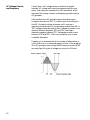
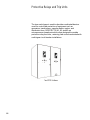
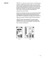
Table of Contents
Introduction .......................................................................................2
Monitoring and Managing Electrical Power with ACCESS .......4
Electrical Power Distribution ..........................................................5
Voltage and Current Values .............................................................9
Changes in Voltage and Current ...................................................16
Frequency and Harmonics ........................................................... 22
Power and Power Factor .............................................................. 27
ACCESS System ........................................................................... 37
WinPM and SIEServe ................................................................... 38
Communication Protocols and Standards ................................. 41
Local Area Networks .................................................................... 44
Serial Communication .................................................................. 46
Power Metering ............................................................................. 54
Power Meter Features .................................................................. 63
Protective Relays and Trip Units ................................................. 66
Circuit Breaker Trip Units .............................................................. 68
SAMMS .......................................................................................... 72
S7 I/O Device ..................................................................................74
Lighting Control System ...............................................................76
ACCESS System Application Example ..................................... 79
Review Answers ........................................................................... 81
Final Exam ...................................................................................... 82
1
Introduction
Welcome to another course in the STEP 2000 series, Siemens
Technical Education Program, designed to prepare our sales
personnel and distributors to sell Siemens Energy &
Automation products more effectively. This course covers
Power Monitoring and Management with ACCESS and
related products.
Upon completion of Power Monitoring and Management
with ACCESS you should be able to:
2
•
Identify five benefits of using the ACCESS system
•
Explain the difference between peak, peak-to-peak,
instantaneous, average, and effective values of AC current
and voltage
•
Identify linear and nonlinear loads
•
Explain various industry terms for voltage conditions
•
Describe a CBEMA curve
•
Explain the effects of harmonics on a distribution system
and associated equipment
•
Explain the difference between true power, reactive power,
and apparent power
•
Identify solutions for various power supply problems
•
Select appropriate power meters for use in a distribution
system
•
Explain various communication standards and network
protocols
•
Explain the use of various components in an ACCESS
controlled distribution system
This knowledge will help you better understand customer
applications. In addition, you will be able to describe products to
customers and determine important differences between
products. You should complete Basics of Electricity before
attempting Power Monitoring and Management with
ACCESS. An understanding of many of the concepts covered in
Basics of Electricity is required for Power Monitoring and
Management with ACCESS.
If you are an employee of a Siemens Energy & Automation
authorized distributor, fill out the final exam tear-out card and
mail in the card. We will mail you a certificate of completion if
you score a passing grade. Good luck with your efforts.
Sentron and Sensitrip are registered trademarks of
Siemens AG. ACCESS, WinPM, SIEServe, SIPROTEC,
Static Trip III, SAMMS and S7/IO are trademarks of Siemens AG.
Other trademarks are the property of their respective owners.
3
Monitoring and Managing Electrical Power
with ACCESS
Siemens ACCESS™ is more than just power meters, trip units,
and other hardware. The ACCESS power management and
control system is a networked system comprised of a variety of
devices that monitor and control an electrical distribution
system. The ACCESS system provides electrical data necessary
for troubleshooting, power quality studies, preventative
maintenance, and cost allocation. A power monitoring and
management system, such as Siemens ACCESS, can identify
potential problems before they cause costly breakdowns.
There are five benefits to using the ACCESS system.
• Reduce or eliminate unplanned outages
• Proactively manage power systems to minimize utility bills
• Automate sub-billing of utility power bills
• Optimize capital equipment used in power systems
• Measure and analyze power quality
4
Electrical Power Distribution
Before discussing the Siemens ACCESS system an
understanding of the production, distribution, and use of electric
power is necessary.
Electric power is produced by converting potential energy into
electricity. There are several sources used to produce electric
power. Coal, oil, and uranium are fuels used to convert water
into steam which in turn drives a turbine. Some utilities also use
gas or a combination of gas and steam turbines. There are other
forms of electric power generation such as hydroelectric and
solar energy plants.
5
Distribution
In order for generated power to be useful it must be transmitted
from the generating plant to residential, commercial, and
industrial customers. Typically, commercial and industrial
applications have higher demands for electric power than
residential applications. Regardless of the size of the electric
system, electric power must be supplied that allows the
intended loads to operate properly.
The most efficient way to transfer energy from the generating
plant to the customer is to increase voltage while reducing
current. This is necessary to minimize the energy lost in heat on
the transmission lines. These losses are referred to as I2R (Isquared-R) losses since they are equal to the square of the
current times the resistance of the power lines. Once the
electrical energy gets near the end user the utility will need to
step down the voltage to the level needed by the user.
Power Quality
6
Electrical equipment is designed to operate on power that is a
specific voltage and frequency. This power should also be free
from quality problems, such as voltage spikes and harmonics.
Unfortunately, power quality problems can occur from various
sources. Power quality problems can affect the performance and
shorten the life of electrical equipment. Power quality problems
can significantly increase the operating cost of an electrical
system.
Loads
Electricity is used to produce motion, light, sound, and heat. AC
motors, which account for about 60% of all electricity used, are
widely used in residential, commercial, and industrial
applications. In today’s modern commercial and industrial
facilities there is increased reliance on electronics and sensitive
computer-controlled systems. Electronic and computer systems
are often their own worst enemy. Not only are they susceptible
to power quality problems, but they are often the source of the
problem.
7
Review 1
1.
Which of the following is a benefit to using the
Siemens ACCESS system?
a. Reduce or eliminate unplanned outages
b. Proactively manage power systems
c. Automate sub-billing of utility power bills
d. Optimize capital equipment used in power systems
e. Measure and analyze power quality
f. All of the above
2.
AC motors account for about ____________ % of all
electricity used.
3.
The most efficient way to transfer energy from the
generating plant to the customer is to increase voltage
while reducing ____________ .
4.
Power quality problems can significantly ____________
the operating cost of an electrical system.
a. increase
b. decrease
8
Voltage and Current Values
An accurate measurement of voltage supplied by the utility and
the current produced by the connected load is necessary in
identifying power usage and power quality problems.
DC
Voltage is either direct current (DC) or alternating current (AC).
DC voltage produces current flow in one direction. DC voltage
can be obtained directly from sources such as batteries and
photocells, which produce a pure DC. DC voltage can also be
produced by applying AC voltage to a rectifier.
Measuring DC Voltage
The value of DC voltage varies. Low level DC voltages, such as
5 - 30 VDC, are commonly used in electronic circuits. Higher
levels of DC voltage, such as 500 VDC, can be used in many
industrial applications to control the speed of DC motors. A
voltmeter is used to measure DC voltage.
9
AC Voltage, Current,
and Frequency
Current flow in AC voltage reverses direction at regular
intervals. AC voltage and current are represented by a sine
wave. Sine waves are symmetrical, 360° waveforms which
represent the voltage, current, and frequency produced by an
AC generator.
If the rotation of an AC generator were tracked through a
complete revolution of 360°, it could be seen that during the
first 90° of rotation voltage increases until it reaches a
maximum positive value. As the generator rotated from 90° to
180°, voltage would decrease to zero. Voltage increases in the
opposite direction between 180° and 270°, reaching a
maximum negative value at 270°. Voltage decreases to zero
between 270° and 360°. This is one complete cycle or one
complete alternation.
Frequency is a measurement of the number of alternations or
cylces that occur in a measured amount of time. If the armature
of an AC generator were rotated 3600 times per minute (RPM)
we would get 60 cycles of voltage per second, or 60 hertz.
10
AC voltage can either be single- or three-phase. While singlephase power is needed for many applications, such as lighting,
utility companies generate and transmit three-phase power.
Three-phase power is used extensively in industrial applications
to supply power to three-phase motors. In a three-phase system
the generator produces three voltages. Each voltage phase
rises and falls at the same frequency (60 Hz in the U.S., 50 Hz in
many other countries); however, the phases are offset from
each other by 120°.
Measuring AC Values
Measuring AC is more complex than DC. Depending on the
situation, it may be necessary to know the peak value, peak-topeak value, instantaneous value, average value, or the RMS
(root-mean-square) value of AC.
Peak Value
The peak value of a sine wave occurs twice each cycle, once
at the positive maximum value and once at the negative
maximum value. The peak voltage of a distribution system
might be 650 volts, for example.
11
Peak-to-Peak Value
The peak-to-peak value is measured from the maximum positive
value to the maximum negative value of a cycle. If the peak
voltage is 650 volts, the peak-to-peak voltage is 1300 volts.
Instantaneous Value
The instantaneous value is the value at any one particular time
along a sine wave. Instantaneous voltage is equal to the peak
voltage times the sine of the angle of the generator armature.
The sine value is obtained from trigonometric tables. The
following table shows a few angles and their sine value.
Angle
30°
60°
90°
120°
150°
180°
Sin θ
0.5
0.866
1
0.866
0.5
0
Angle
210°
240°
270°
300°
330°
360°
Sin θ
-0.5
-0.866
-1
-0.866
-0.5
0
The instantaneous voltage at 150° of a sine wave with a peak
voltage of 650 volts, for example, is 325 volts (650 x 0.5).
12
Average Value
The average value of a sine wave is zero. This is because the
positive alternation is equal and opposite to the negative
alternation. In some circuits it may be necessary to know the
average value of one alternation. This is equal to the peak
voltage times 0.637. The average value of a distribution system
with 650 volts peak, for example, is 414.05 volts (650 x 0.637).
Effective Value
The effective value, also known as RMS (root-mean-square), is
the common method of expressing the value of AC. The
effective value of AC is defined in terms of an equivalent
heating effect when compared to DC. One RMS ampere of
current flowing through a resistance will produce heat at the
same rate as a DC ampere. The effective value is 0.707 times
the peak value. The effective value of a system with 650 volts
peak, for example, is 460 volts (650 x 0.707 = 459.55 volts).
13
Linear Loads
It is important at this point to discuss the differences between a
linear and nonlinear load. A linear load is any load in which
voltage and current increase or decrease proportionately.
Voltage and current may be out of phase in a linear load, but the
waveforms are sinusoidal and proportionate. Motors, resistive
heating elements, incandescent lights, and relays are examples
of linear loads. Linear loads can cause a problem in a
distribution system if they are oversized for the distribution
system or malfunction. They do not cause harmonic distortion,
which will be discussed later.
Nonlinear Loads
When instantaneous load current is not proportional to
instantaneous voltage the load is considered a nonlinear load.
Computers, television, PLCs, ballested lighting, and variable
speed drives are examples of nonlinear loads. Nonlinear loads
can cause harmonic distortion on the power supply. Harmonics
will be discussed later in the course.
14
Crest Factor
Crest factor is a term used to describe the ratio of the peak
value to the effective (RMS) value. A pure sinusoidal waveform
has a crest factor of 1.41. A crest factor other than 1.41 indicates
distortion in the AC waveform. The crest factor can be greater or
lower than 1.41, depending on the distortion. High current
peaks, for example, can cause the crest factor to be higher.
Measuring the crest factor is useful in determining the purity of
a sine wave.
Conversion Chart
When using different types of test equipment it may be
necessary to convert from one AC value to another. A voltmeter,
for example, may be calibrated to read the RMS value of
voltage. For purpose of circuit design, the insulation of a
conductor must be designed to withstand the peak value, not
just the effective value.
To Convert
Peak-to-Peak
Peak
Peak
Peak
RMS
RMS
Average
Average
To
Peak
Peak-to-Peak
RMS
Average
Peak
Average
Peak
RMS
Multiply By
0.5
2
0.707
0.637
1.414
0.9
1.567
1.111
15
Changes in Voltage and Current
Even the best distribution systems are subject to changes in
system voltage from time-to-time. The following industry terms
can be used to describe given voltage conditions. Voltage
changes can range from small voltage fluctuations of short
duration to a complete outage for an extended period of time.
Term
Condition
Voltage
Fluctuations
Increase or decrease in normal line voltage within the
normal rated tolerance of the electronic equipment.
Usually short in duration and do not affect equipment
performance.
Voltage Sag
Decrease in voltage outside the normal rated
tolerance of the electronic equipment. Can cause
equipment shutdown. Generally, two seconds or less
in duration.
Voltage Swell
Increase in voltage outside the normal rated tolerance
of the electronic equipment. Can cause equipment
failure. Generally, two seconds or less in duration.
Decrease/increase in voltage outside the normal rated
Long-Term
tolerance of the electronic equipment. Can adversly
Under/Overvoltage affect equipment. Lasts more than a few seconds in
duration.
Outage/Sustained Complete loss of power. Can last from a few
Power Interruption milliseconds to several hours.
16
Sags and undervoltage can be caused when high current loads,
such as large motors are started. Undervoltage may also occur
when a power utility reduces the voltage level to conserve
energy during peak usage. Undervoltage is also commonly
caused by overloaded transformers or improperly sized
conductors.
Swells and overvoltage can be caused when high current loads
are switched off, such as when machinery shuts down.
Overvoltage may occur on loads located near the beginning of a
power distribution system or improperly set voltage taps on a
transformer secondary.
Voltage and
Current Unbalance
Voltage unbalance occurs when the phase voltages in a threephase system are not equal. One possible cause of voltage
unbalance is the unequal distribution of single-phase loads. In
the following illustration loads are equally divided.
17
In this illustration, however, loads are unevenly divided. A large
number of lighting and small appliance loads are connected to
phase C . This can cause the voltage on phase C to be lower.
Because a small unbalance in voltage can cause a high current
unbalance, overheating can occur in the C phase winding of the
3-phase motor. In addition, the single-phase motors connected
to phase C are operating on a reduced voltage. These loads will
also experience heat related problems.
Transient Voltage
18
A transient voltage is a temporary, undesirable voltage that
appears on the power supply line. Transient voltages can range
from a few volts to several thousand volts and last from a few
microseconds to a few milliseconds. Transients can be caused
by turning off high inductive loads, switching large power factor
correction capacitors, and lightning strikes.
CBEMA and IEEE
The U.S. Department of Commerce, working with the Computer
Business Equipment Manufacturers Association (CBEMA),
published a set of guidelines for powering and protecting
sensitive equipment. These guidelines were published in 1983
in FIPS Publication 94. As the use of computers has grown,
other organizations have made additional recommendations.
The Institute of Electrical and Electronic Engineers (IEEE)
published IEEE 446-1987 which recommends engineering
guidelines for the selection and application of emergency and
standby power systems. While it is beyond the scope of this
book to discuss in detail the recommendations of these
documents it is useful to discuss their intent.
CBEMA Curve
The CBEMA curve is a useful tool that can be used as a
guideline in designing power supplies for use with sensitive
electronic equipment. The vertical axis of the graph is the
percent of rated voltage applied to a circuit. The horizontal axis
is the time the voltage is applied. The CBEMA curve illustrates
an acceptable voltage tolerance envelope. In general, the
greater the voltage spike or transient, the shorter the duration it
can occur. Voltage breakdown and energy flow problems can
occur when the voltage is outside the envelope.
19
Power Disturbance Types
There are three types of power disturbances. Type I
disturbances are transient and oscillatory overvoltages lasting
up to 0.5 Hz. Type I disturbances can be caused by lightning or
switching of large loads on the power distribution system. Type
II disturbances are overvoltages and undervoltages which last
from 0.5 to 120 Hz. Type II disturbances can be caused by a fault
on the power distribution system, large load changes, or
malfunctions at the utility. Type III disturbances are outages
lasting greater than 120 hertz.
Studies have shown that sensitive computer equipment is most
vulnerable during a Type I overvoltage disturbance and a Type II
undervoltage disturbance. Type II undervoltage disturbances are
the most common cause of failure in sensitive computer
equipment. It is important to note that the precise extent to
which computers and other sensitive equipment is susceptible
is difficult to determine.
20
Review 2
1.
____________ is a measurement of the number of
alternations between positive and negative peak values
in a measured amount of time.
a. voltage
b. current
c. frequency
d. power
2)
The peak-to-peak value of an AC voltage with a peak
voltage of 600 volts is ____________ .
3)
The instantaneous voltage measured at 120° of a sine
wave with a peak voltage of 650 volts is ___________ .
4)
The most common method of expressing the value of
AC voltage and current is ____________ value.
a. average
b. effective
c. peak
d. instantaneous
5)
A pure sinusoidal waveform has a crest factor of
____________ .
6)
Computer equipment is most vulnerable during a Type I
overvoltage disturbance and a Type ____________
undervoltage disturbance.
a. I
b. II
c. III
21
Frequency and Harmonics
We learned earlier that frequency is a measurement of the
number of times voltage and current rises and falls to
alternating peak values per second. Frequency is stated in hertz.
The standard power line frequency in the United States is 60
hertz (60 cycles per second). In many other parts of the world
the standard frequency is 50 hertz.
Harmonics
Harmonics are created by electronic circuits, such as, adjustable
speed drives, rectifiers, personal computers, and printers.
Harmonics can cause problems to connected loads.
The base frequency of the power supply is said to be the
fundamental frequency or first harmonic. The fundamental
frequency or first harmonic of a 60 Hz power supply is 60 Hz.
Additional harmonics can appear on the power supply. These
harmonics are usually whole number multiplies of the first
harmonic. The third harmonic of a 60 Hz power supply, for
example, is 180 Hz (60 x 3).
22
When a harmonic waveform is superimposed on the
fundamental sine wave a distinctive waveform is produced. In
this example, the third harmonic is seen superimposed on the
fundamental frequency. The problem of waveform distortion
becomes more complex when additional harmonics are
present.
Total Harmonic Distortion
Harmonic distortion is a destructive force in power distribution
systems. It creates safety problems, shortens the life span of
transformers, and interferes with the operation of electronic
devices. Total harmonic distortion (THD) is a ratio of harmonic
distortion to the fundamental frequency. The greater the THD
the more distortion there is of the 60 Hz sine wave. Harmonic
distortion occurs in voltage and current waveforms. Typically,
voltage THD should not exceed 5% and current THD should not
exceed 20%. Some of the power meters offered by Siemens
are capable of reading THD.
Phasors
Phase rotation describes the order in which waveforms from
each phase cross zero. Waveforms can be used to illustrate this
relationship. Phasors consist of lines and arrows and are often
used in place of waveforms for simplification.
23
Harmonic Sequence
A harmonic’s phase rotation relationship to the fundamental
frequency is known as harmonic sequence. Positive sequence
harmonics (4th, 7th, 10th, ...) have the same phase rotation as
the fundamental frequency (1st). The phase rotation of negative
sequence harmonics (2nd, 5th, 8th, ...) is opposite the
fundamental harmonic. Zero sequence harmonics (3rd, 6th,
9th, ...) do not produce a rotating field.
Harmonic
1st
2nd
3rd
4th
5th
6th
7th
8th
9th
10th
Frequency
60
120
180
240
300
360
420
480
540
600
Sequence
Fundamental
Negative
Zero
Positive
Negative
Zero
Positive
Negative
Zero
Positive
Odd numbered harmonics are more likely to be present than
even numbered harmonics. Higher numbered harmonics have
smaller amplitudes, reducing their affect on the power and
distribution system.
24
Harmonic Effects
All harmonics cause additional heat in conductors and other
distribution system components. Negative sequence harmonics
can be problematic in induction motors. The reverse phase
rotation of negative harmonics reduces forward motor torque
and increases the current demand.
Zero sequence harmonics add together, creating a single-phase
signal that does not produce a rotating magnetic field. Zero
sequence harmonics can cause additional heating in the neutral
conductor of a 3Ø, 4-wire system. This can be a major problem
because the neutral conductor typically is not protected by a
fuse or circuit breaker.
25
K Factor
26
K factor is a simple numerical rating that indicates the extra
heating caused by harmonics. A transformer’s ability to handle
the extra heating is determined by a K factor rating. A standard
transformer has a rating of K-1. A transformer might have a rating
of K-5, which would be an indication of the transformer’s ability
to handle 5 times the heating effects caused by harmonics than
a K-1 rated transformer.
Power and Power Factor
Load Types
Distribution systems are typically made up of a combination of
various resistive, inductive, and capacitive loads.
Resistive Loads
Resistive loads include devices such as heating elements and
incandescent lighting. In a purely resistive circuit, current and
voltage rise and fall at the same time. They are said to be “in
phase.”
True Power
All the power drawn by a resistive circuit is converted to useful
work. This is also known as true power in a resistive circuit. True
power is measured in watts (W), kilowatts (kW), or megawatts
(MW). In a DC circuit or in a purely resistive AC circuit, true
power can easily be determined by measuring voltage and
current. True power in a resistive circuit is equal to system
voltage (E) times current (I).
In the following example, an incandescent light (resistive load)
is connected to 120 VAC. The current meter shows the light is
drawing 0.833 amps. In this circuit 100 watts of work is done
(120 VAC x 0.833 amps).
27
Inductive Loads
Inductive loads include motors, transformers, and solenoids. In
a purely inductive circuit, current lags behind voltage by 90°.
Current and voltage are said to be “out of phase.” Inductive
circuits, however, have some amount of resistance. Depending
on the amount of resistance and inductance, AC current will lag
somewhere between a purely resistive circuit (0°) and a purely
inductive circuit (90°). In a circuit where resistance and
inductance are equal values, for example, current lags voltage
by 45°.
Capacitive Loads
Capacitive loads include power factor correction capacitors and
filtering capacitors. In a purely capacitive circuit, current leads
voltage by 90°. Capacitive circuits, however, have some amount
of resistance. Depending on the amount of resistance and
capacitance, AC current will lead voltage somewhere between
a purely resistive circuit (0°) and a purely capacitive circuit (90°).
In a circuit where resistance and capacitance are equal values,
for example, current leads voltage by 45°.
28
Reactive Loads
Circuits with inductive or capacitive components are said to be
reactive. Most distribution systems have various resistive and
reactive circuits. The amount of resistance and reactance varies,
depending on the connected loads.
Reactance
Just as resistance is opposition to current flow in a resistive
circuit, reactance is opposition to current flow in a reactive
circuit. It should be noted, however, that where frequency has
no effect on resistance, it does effect reactance. An increase in
applied frequency will cause a corresponding increase in
inductive reactance and a decrease in capacitive reactance.
Energy in Reactive Circuits
Energy in a reactive circuit does not produce work. This energy
is used to charge a capacitor or produce a magnetic field around
the coil of an inductor. Current in an AC circuit rises to peak
values (positive and negative) and diminishes to zero many
times a second. During the time current is rising to a peak
value, energy is stored in an inductor in the form of a magnetic
field or as an electrical charge in the plates of a capacitor. This
energy is returned to the system when the magnetic field
collapses or when the capacitor is discharged.
29
Reactive Power
Power in an AC circuit is made up of three parts; true power,
reactive power, and apparent power. We have already discussed
true power. Reactive power is measured in volt-amps reactive
(VAR). Reactive power represents the energy alternately stored
and returned to the system by capacitors and/or inductors.
Although reactive power does not produce useful work, it still
needs to be generated and distributed to provide sufficient true
power to enable electrical processes to run.
Apparent Power
Not all power in an AC circuit is reactive. We know that reactive
power does not produce work; however, when a motor rotates
work is produced. Inductive loads, such as motors, have some
amount of resistance. Apparent power represents a load which
includes reactive power (inductance) and true power
(resistance). Apparent power is the vector sum of true power,
which represents a purely resistive load, and reactive power,
which represents a purely reactive load. A vector diagram can
be used to show this relationship. The unit of measurement for
apparent power is volt amps (VA). Larger values can be stated in
kilovolt amps (kVA) or megavolt amps (MVA).
Power Factor
Power factor (PF) is the ratio of true power (PT) to apparent
power (PA), or a measurement of how much power is
consumed and how much power is returned to the source.
Power factor is equal to the cosine of the angle theta in the
above diagram. Power factor can be calculated with the
following formulas.
30
Power factor can be given as a percent or in decimal format. The
following table shows the power factor for a few sample angles.
Angle
Theta
0
10
20
30
45
60
70
80
90
Cosine of
Angle
Theta
1
0.98
0.94
0.87
0.70
0.50
0.34
0.17
0
Power
Factor (%)
100%
98%
94%
87%
70%
50%
34%
17%
0%
Power
Factor
(Decimal)
1
.98
.94
.87
.7
.5
.34
.17
0
In purely resistive circuits, apparent power and true power are
equal. All the power supplied to a circuit is consumed or
dissipated in heat. The angle of theta is 0° and the power factor
is equal to 1. This is also referred to as unity power factor. In
purely reactive circuits, apparent power and reactive power are
equal. All power supplied to a circuit is returned to the system.
The angle theta is 90° and the power factor is 0. In reality, all AC
circuits contain some amount of resistance and reactance. In a
circuit where reactive power and true power are equal, for
example, the angle of theta is 45° and power factor is 0.70.
31
Power Factor Problems
It can be seen that an increase in reactive power causes a
corresponding decrease in power factor. This means the power
distribution system is operating less efficiently because not all
current is performing work. For example, a 50 kW load with a
power factor of 1 (reactive power = 0) could be supplied by a
transformer rated for 50 kVA. However, if power factor is 0.7
(70%) the transformer must also supply additional power for the
reactive load. In this example a larger transformer capable of
supplying 71.43 kVA (50 ÷ 70%) would be required. In addition,
the size of the conductors would have to be increased, adding
significant equipment cost.
The Cost of Power
Utility companies sell electrical power based on the amount of
true power measured in watts (W). However, we have learned
that in AC circuits not all power used is true power. The utility
company must also supply apparent power measured in voltamps (VA). Typically utilities charge additional fees for increased
apparent power due to poor power factor.
32
The following table shows the amount of apparent power (VA =
W ÷ PF) required for a manufacturing facility using 1 MW
(megawatt) of power per hour for a few sample power factors. If,
for example, a manufacturing facility had a power factor of 0.70
the utility company would have to supply 1.43 MVA (mega voltamps) of power. If the power factor were corrected to 0.90 the
power company would only have to supply 1.11 MVA of power.
True
Power
(MW)
True
Power
1
Leading and Lagging
Power Factor
Power
Factor
÷ Power
Factor
1
0.95
0.90
0.85
0.80
0.75
0.70
Apparent
Power
(MVA)
= Apparent
Power
1
1.053
1.11
1.18
1.25
1.33
1.43
Since current leads voltage in a capacitive circuit, power factor
is considered leading if there is more capacitive reactance than
inductive reactance. Power factor is considered lagging if there
is more inductive reactance than capacitive reactance since
current lags voltage in a inductive circuit. Power factor is unity
when there is no reactive power or when inductive reactance
and capacitive reactance are equal, effectively cancelling each
other.
It is usually more economical to correct poor power factor than
to pay large utility bills. In most industrial applications motors
account for approximately 60% or more of electric power
consumption, resulting in a lagging power factor (more
inductive than capacitive). Power factor correction capacitors
can be added to improve the power factor.
33
Power Demand
Demand is the average energy consumed over a specified
period of time. The interval is usually determined by the utility
company and is typically 15 or 30 minutes. The utility measures
the maximum demand over the 15 or 30 minute period. Utility
companies must install larger equipment to handle irregular
demand requirements. For this reason utility companies may
charge large customers an additional fee for irregular power
usage during peak times. If the maximum demand is greater
than the average consumption, the utility company will need to
provide increased generating capacity to satisfy the higher
demand. Demand is usually low in the morning and evening.
During the day there is more demand for electrical power.
Siemens power meters have a sliding window adjustment that
allows the user to monitor time segments specified by the
utility company.
34
Solutions
As we have learned, there are a number of things that can affect
power quality. The following table provides some basic
guidelines to solve these problems. It should be remembered
that the primary cause and resulting effects on the load and
system should be considered when considering solutions.
Problem
Sag
Swell
Undervoltage
Overvoltage
Momentary
Power
Interruption
Noise
Transients
Harmonics
Power Factor
Effect
Computer shutdown
resulting in lost data,
lamp flicker, electronic
clock reset, false alam.
Shorten equipment life
and increase failure due
to heat.
Computer shutdown
resulting in lost data,
lamp flicker, electronic
clock reset, false alam.
Life expectency of
motor and other
insulation resulting in
equipment failure or fire
hazard. Shorten life of
light bulbs
Computer shutdown
resulting in lost data,
lamp flicker, electronic
clock reset, false alam,
motor circuits trip.
Erractic behavior of
electronic equipment,
incorrect data
communication
between computer
equipment and field
devices.
Premature equipment
failure, computer
shutdown resulting in
lost data.
Overheated neutrals,
wires, connectors,
transformers,
equipment. Data
communication errors.
Increased equipment
and power costs
Solution
Voltage regulator, power
line conditioner, proper
wiring.
Voltage regulator, power
line conditioner.
Voltage regulator, power
line conditioner, proper
wiring.
Voltage regulator, power
line conditioner.
Voltage regulator, power
line conditioner, UPS
system.
Line filters and
conditioners, proper
wiring and grounding.
Surge suppressor, line
conditioner, isolation
transformers, proper
wiring, grounding.
Harmonic filters, K-rated
transformers, proper
wiring and grounding.
Power factor correction
capacitors.
35
Review 3
1.
The second harmonic of a 60 Hz power supply is
____________ Hz.
2.
Typically, the total harmonic distortion (THD) of a
voltage waveform should not exceed ____________ %.
3.
____________ sequence harmonics do not produce a
rotating magnetic field.
a. Positive
b. Negative
c. Zero
4.
A transformer’s ability to handle the extra heating
caused by harmonics is determined by a ____________
rating.
5.
In a purely ____________ circuit, voltage and current are
in phase.
a. resistive
b. inductive
c. capacitive
6.
____________ power represents a load which includes
reactive power and true power.
7.
____________ is the ratio of true power to apparent
power.
8.
An increase in reactive power would require a
corresponding ____________ in transformer size.
a. increase
b. decrease
9.
It is possible to correct for sag with the addition of a
____________ .
a. voltage regulator
b. power line conditioner
c. proper wiring
d. all of the above
36
ACCESS System
Up to this point we have looked at how various factors effect
power quality. The following sections will focus on components
of the ACCESS system and how they can be used as a
complete power monitoring and management system.
Supervisory Devices
In general, ACCESS works on two levels: supervisory and field.
Supervisory devices, such as WinPM™, collects and displays
information from a network of field devices. A supervisory
device sends requests and receives feedback from field
devices over a serial network. This process, called polling,
allows the supervisory and field devices to exchange
information. Siemens WinPM software runs on a personal
computer (PC).
Field Devices
Field devices include meters, circuit breakers, protective relays,
I/O devices, motor protectors, and personal computers (PCs).
Field devices send and receive information about an electrical
system.
In the following sections we will look at ACCESS system
products used as supervisory devices, in network
communication, and field devices.
37
WinPM and SIEServe
WinPM
WinPM™ is supervisory software designed for monitoring and
control of any facility’s electrical distribution system. WinPM
can run on a single computer or in a networked environment.
Multiple computers running WinPM can share data and control
devices over a LAN using TCP/IP. WinPM can monitor an entire
electrical system consisting of hundreds of field devices in
multiple locations.
Electrical System
Management
WinPM monitors and collects data of an electrical system by
interfacing to any communicating electrical device such as
power meters, relays, and trip units. Alarms can be setup to
trigger if a specific value, such as voltage, current, or KW
demand, is exceeded. Alarms can alert via audible and visual
messages on a PC, fax, or pager message, and/or automatically
control a connected device.
38
Analysis
Power quality, such as transients, sags, swells, and harmonics,
can be monitored and analyzed by viewing triggered
waveforms, continuous data sampling, relay trip logs, and
setpoint event messages.
Historical data logs can be generated to provide load profile
information, kilowatt demand usage patterns, harmonic, and
power factor trends. These historical data logs can provide
trending on any measured value.
Device Configuration
ACCESS field devices can be configured remotely by specifying
protective settings. Certain field devices can be configured to
record waveforms.
Device Control
Certain devices can be controlled directly from WinPM. For
example, motors can be started and stopped using Siemens
Advanced Motor Master System (SAMMS) devices.
SIEServe
SIEServe™ is another electrical distribution software product
designed by Siemens. SIEServe allows for the retrieval and
display of data from Siemens power meters, trip units, and
relays. SIEServe, though not as robust as WinPM, provides a
simple way to monitor an electrical distribution system from a
desktop. Data retrieved by SIEServe can be linked to
spreadsheets for charting or word processing programs for other
reporting functions. SIEServe does not have the control
capabilities of WinPM.
39
Industrial Computer
40
Siemens software, such as WinPM and SIEServe, will run on
most personal computers. In some applications it may be
desirable to locate a supervisory computer in a harsh industrial
environment. The Siemens industrial personal computer was
designed for this purpose. The Siemens industrial computer is
dust proof and drip proof to NEMA 4, NEMA 4X, and NEMA 12
specifications. There is a 10.4” flat screen monitor and full
keypad with an integrated pointing device. This computer is
designed for panel mounting.
Communication Protocols and Standards
The ACCESS system allows a variety of devices to
communicate electronically. In the following illustration, for
example, several power meters are connected to a single
computer.
Straight-Line Topology
Field devices can be connected to supervisory devices with
either straight-line or loop topology. In straight-line topology the
supervisory device connects to a field device, which in turn
connects to another field device, terminating at the farthest
device. Straight-line topology allows for longer runs; however, if
a break in the line should occur the supervisory device would
be unable to communicate with devices on the far side of the
break.
41
Loop Topology
In loop topology the cable is connected in a similar manner to
straight-line topology. Rather than terminating the connection at
the farthest device, a complete loop is formed by bringing the
cable back to the supervisory device. Loop topology requires
more cable than straight-line topology, which adds expense to
the system and shortens the distance from the last device on
the loop to the supervisory device. The main advantage to loop
topology is the ability to continue to communicate with each
device if there is a break in the system.
Protocols
Network protocols are rules that allow devices to communicate
with each other. A protocol identifies how devices should
identify each other, the form communicated data takes, and how
the data is interpreted at its final destination. Several protocol
standards have evolved in the electrical industry. Siemens
ACCESS supports the following protocols at various levels.
PROFIBUS DP
PROFIBUS DP is an open bus standard for a wide range of
applications in various manufacturing and automation
applications. PROFIBUS DP works at the field device level such
as, power meters, I/O devices, motor protectors, circuit
breakers, and lighting controls. An advantage to PROFIBUS DP
is the ability to communicate between devices of different
manufacturers.
42
ModBus RTU
ModBus RTU is a protocol originally developed by MODICON,
which is now part of Schneider Automation. ModBus RTU
protocol has been widely used by other companies.
DNP 3.0
Distributed Network Protocol 3.0 (DNP 3.0) was developed by
Harris Distributed Automation Products. This protocol is an
open and public protocol based on standards developed by the
International Electrotechnical Commission (IEC). This protocol is
often used by large power utility companies.
SEABus and SEABus Plus
The rules that govern the communication of the ACCESS
system are known collectively as SEABus and SEABus Plus.
Both protocols are used to communicate between supervisory
and field devices. SEABus and SEABus Plus are open protocols
available to anyone who wants to connect their equipment to
the ACCESS system.
A supervisory device can support unlimited field devices. Each
field device in the ACCESS system has a unique address. A
packet is simply a unit of data that is routed between an origin
(supervisory device) and a destination (field device). Data bytes
are grouped into packets containing from 5 to 260 characters.
Data bytes contain a unique address for a given field device and
instructions for the field device.
A supervisory device, for example, may initiate communication
by sending a packet requesting information such as voltage
from a specific field device. The field device would respond by
sending a packet back with the requested information.
43
Local Area Networks
Local Area Network (LAN)
In any complex power monitoring system the need for rapid
information flow is critical. Conditions at any point in the system
may impact the entire power distribution system. This need for
information flow often requires that intelligent devices, such as
supervisory PCs, be interconnected by a local area network
(LAN). A LAN is a communication system designed for private
use in a limited area.
A node is an active device, such as a computer or printer,
connected to the network. A LAN can be arranged with nodes
in a bus, star, or a combination of bus and star.
One example of a widely used LAN is Ethernet. Ethernet uses a
bus topology and an access control system that allows devices
to initiate communication only if a carrier signal is not present.
By comparison, Token Ring networks use a ring topology and a
signal called a token to determine which device can
communicate.
44
Ethernet Converter
The Siemens Ethernet converter connects many ACCESS field
devices throughout a facility to a supervisory computer. The
Ethernet converter can be configured so that Siemens ACCESS
components can communicate through the Ethernet or Token
Ring.
The Ethernet converter can connect RS-232 and RS-485
devices directly to a LAN.
The converter is also capable of connecting up to two protocols,
such as SEABus and ModBus RTU.
45
Serial Communication
RS-232 and RS-485 are Electronic Industries Association (EIA)
specifications commonly used for serial data communication.
Siemens ACCESS devices support the RS-485 as standard.
Some ACCESS devices also support the RS-232 standard.
RS-232
46
RS-232 is a serial communication protocol which sends and
receives information through twisted pair cable. It is common to
see both 9-pin and 25-pin RS-232 connectors. It is important to
note that although the RS-232 standard consists of 25
transmission lines, many applications do not require all the lines
available. Depending on the device, manufacturers use various
combinations of the transmission lines available. The following
illustration, for example, shows the connector requirements for
equipment used in the Siemens ACCESS system.
RS-232 uses what is referred to as an unbalanced signal or
communication method. There is one signal wire for each
circuit with a common return. The driver sends a series of binary
signals to the receiver. These binary pulses make up predefined
words that either give the status of a system being monitored or
provide commands to control an event. This method is
susceptible to unwanted electrical noise. The RS-232 standard
supports only one driver (transmitter) and one receiver with
distances limited to no greater than 50 feet.
RS-485
RS-485 is a communication standard that is better suited for
industrial applications that involve distances greater than 50
feet. The RS-485 standard can support up to 32 devices over a
maximum distance of 4000 feet.
The RS-485 standard uses a twisted pair of wires for each circuit
with differential drivers and receivers. This method provides a
balanced signal which cancels out signal noise to allow for
better data integrity.
47
Typically, at the top level of a communication system is a host
computer with an RS-232 interface. The host computer may
have to communicate with an RS-485 device. In this situation a
converter, such as a Siemens isolated multi-drop converter can
be used.
Isolated Multi-Drop
Converter
48
The Isolated Multi-Drop Converter is an RS-232 to RS-485
converter that provides connectivity between a computer’s RS232 serial port and a Siemens SEABus RS-485 communications
loop for ACCESS field devices. A multi-drop converter will
accept up to four RS-485 input loops. Each input loop will
support up to 32 devices. One isolated multi-drop converter can
handle up to 128 field devices.
Using the Isolated
Muli-Drop Converter
In the following illustration a computer communicates with
various ACCESS field devices through an RS-232 interface and
isolated multi-drop converter.
Communicating on a LAN
Field devices in the Siemens ACCESS product line that cannot
communicate directly on a LAN, such as Ethernet, can be
connected to the LAN through an Ethernet converter. When
more than 32 field devices are used an isolated multi-drop
converter is also required.
49
Modem
Modems are electronic devices used for sending and receiving
data over long distances. The Siemens ACCESS system also
supports data communication through a modem. In the
following illustration a remote computer communicates to an
isolated multi-drop converter through a modem.
Fiber Optics
Fiber optics is a method for transmitting data using light. A basic
system consists of a transmitting device which generates a light
signal, a fiber optic cable, and a receiving device. In the
following illustration a supervisory computer is connected to a
fiber optic converter through an RS-232 interface. At the other
end of the fiber optic cable is another RS-232 to fiber optic
converter which is connected to an isolated multi-drop
converter. The RS-485 output of the multi-drop converter is
connected to various field devices.
50
DTU3005
The DTU3005 is a multiple-function data transfer unit, which
acts as an intelligent device to request information from up to
32 ACCESS devices. The requested information is then made
available to PLCs and various industrial automation networks
such as ModBus and PROFIBUS DP. There are two models, the
DTU3005-P and DTU3005-B.
The following illustration shows two possible configurations.
Up to 32 Siemens ACCESS devices can be connected to one
port of the DTU3005. In one example, a PLC or ModBus master
device can be connected to one port of a DTU3005-B. A second
ModBus device or an optional supervisory PLC can be
connected with SEABus to another port.
In the second example, PROFIBUS devices are connected via
an RS-485 port on the DTU3005-P. A supervisory PC is
connected to an available port.
51
Local Display Unit
The Local Display Unit (LDU) works with the SEABus network
to poll data from Siemens ACCESS compatible devices. The
LDU can be mounted in harsh industrial environments and is
suitable for mounting in panelboards, switchboards, and
switchgear.
The LDU can be connected through SEABus to up to 32
ACCESS devices. A second port can be connected through
RS-232 to a WinPM monitoring station.
52
Review 4
1.
WinPM is an example of a ____________ device.
a. supervisory
b. field
2.
A Siemens ACCESS power meter is an example of a
____________ device.
a. supervisory
b. field
3.
The rules that govern the communication fo the
ACCESS system are known collectively as
____________ and ____________ Plus.
4.
A ____________ is an active device, such as a computer
or printer, connected to the network.
5.
Siemens ____________ ____________ can connect
RS-232 and RS-485 devices directly to a LAN.
6.
RS-232 is limited to transmission distances no greater
than ____________ feet.
7.
RS-485 can support 32 different drivers and receivers
over a maximum distance of ____________ feet.
8.
The LDU can be connected to up to ____________
ACCESS devices.
53
Power Metering
In today’s electronic environment, power management requires
sophisticated meters. Voltage, current, and kW meters alone do
not provide an adequate indication of power quality and energy
consumption. Siemens power meters, in addition to measuring
voltage, current, frequency, harmonics energy, power, and
power factor, also capture system disturbances, log historical
data, monitor the status of other equipment, and control loads.
54
Meter Location
Power meters should be located at key points in the electrical
distribution system to effectively monitor power consumption
and quality. In some applications, it is sufficient to monitor
energy consumption on significant loads and monitor power
quality at the utility supply point. In critical power applications it
may be desirable to monitor power quality throughout the
distribution system.
55
9230 Meter
The 9230 power meter measures real power. It will provide a
readout of watts, watt-hours, and watt demand (configurable
demand period). The 9230 is a full four-quadrant power meter
providing bidirectional monitoring and separate positive and
negative watt-hour accumulators.
The 9230 meter measures voltage and current to calculate
power. Alarm functions can be programmed to operate two
relay contacts. A KYZ relay provides pulses for energy
management systems. These pulses represent accumulated
positive or negative watt-hours. The pulse value is configurable.
SEABus communication converters or analog output modules
are available.
56
4300 Meter
The 4300 meter provides a readout of phase current, average
phase current, line voltage, average line voltage, frequency,
watts, watt-hours, peak watt demand, and power factor. Like the
9230, the 4300 is a full four-quadrant power meter. A standard
communications module connects the 4300 to the Siemens
ACCESS system. A separate display eliminates the need for
voltage transformers on most low voltage applications because
line voltage can be connected directly to the base module.
The 4300 meter is designed to fit in new or retrofit applications.
The display unit will fit standard U.S. analog meter drilling
patterns.
57
9240 Meter
The 9240 meter provides all significant parameters of the power
system including; 3-phase volts, 3-phase current, neutral
current, watts, VAR, VA, watt-hours, power factor, and frequency.
The 9240 records the maximum and minimum values for most
measured parameters. Three KYZ pulses are available for energy
readings. The 9240 uses standard cutouts and will replace most
existing analog meters.
The 9240 has several protocol options to support many
systems. Available protocols include SEABus (for the ACCESS
system), ModBus RTU, ModBus Plus, and DNP 3.0.
9300 Meter
The 9300 meter also provides all significant parameters of the
power system. The 9300 meter can make predicted demand
calculations based on past data. The 9300 meter monitors
individual phase harmonics (up to the 15th), total harmonic
distortion, and K-factor.
The 9300 includes four binary outputs that can be operated from
remote software or configured as kWH pulse signals. The 9300
comes standard with SEABus (for the ACCESS System) and
ModBus RTU or, optionally, with PROFIBUS DP. An Ethernet
card may also be installed.
58
The 9300 includes a front optical data port for accessibility by a
portable PC.
9330 Meter
The 9330 meter offers the same features as the 9300 meter. In
addition, the 9330 includes setpoint capability to operate any of
the four binary outputs. All events are recorded in the event log.
The 9330 can also sample data continuously for future trend
analysis.
The 9330 meter features Ethernet or telephone modem
connections as options. The 9330 can act as a gateway
between these connections and other devices that are
connected to the 9330 with an RS-485 cable. The 9330 comes
standard with SEABus, ModBus RTU, and DNP 3.0.
59
4700 Meter
In addition to providing information on all significant parameters
of a power system, the 4700 includes waveform capture for
harmonic analysis up to the 63rd harmonic. The 4700 includes 4
binary inputs and 1 analog input to monitor external equipment.
There are 3 relay outputs that can be operated by set-points or
used as kWh and kVARH pulse signals. The 4700 meter also
includes one transducer-type analog output.
4720 Meter
60
The 4720 meter provides all of the same features as the 4700
meter. In addition, the 4720 provides on-board harmonic
analysis up to the 15th harmonic. Like the 9330, the 4720 logs
events and does continuous data sampling. The 4720 provides a
2-cycle trigger to record up to 36 cycles of a disturbance. The
4720 has an optional communications card for SEABus
protocol.
9500 Meter
The 9500 offers three-phase power monitoring on a large, easy
to read screen. The 9500 meter monitors K-factor, crest factor,
individual harmonics, and total harmonics up to the 63rd
harmonic.
In addition to displaying values, the 9500 also displays graphical
phasor diagrams and bar graph representations. The 9500
provides a 0.5 cycle trigger and up to 4 MB of memory for
extensive waveform recording of system disturbances, as well
as a special sag/swell module.
Advanced features include utility-style rate structure
calculations. The 9500 meter meets the accuracy requirements
of the ANSI C12.20 revenue standard. The 9500 provides
transformer and line loss calculations. The 9500 can
communicate with the Internet and transmit email.
The 9500 comes standard with several protocols including
SEABus, ModBus RTU, and DNP 3.0. In addition to RS-232 and
RS-485, the 9500 can include a telephone modem, an Ethernet
card, and a fiber optic port. Simultaneous connections are
supported.
The 9500 can be equipped with 7 binary outputs, 16 binary
inputs, 4 analog outputs, and 4 analog inputs.
61
Another unique feature of the 9500 is the optional ability to
connect to the Global Position Satellite (GPS) system for time
synchronization with other 9500 meters in the distribution
system.
62
Power Meter Features
Siemens power meters have various features, depending on
specific application needs. With a number of meters to choose
from it may seem confusing when trying to decide which meter
is right for which job. The following chart and tables are provided
to help identify various features and performance capabilities for
Siemens power meters. The chart is arranged in order of
performance feature. The table on the following page details
available features for each power meter.
63
Data Logging
Display
I/O
Advanced Functions
Communications
64
Real Power
Bi-Directional Energy
Sliding Window Demand
Reactive & Apparent Power
Voltage & Current
Power Factor
Frequency
Harmonic Analysis
Thermal & Predicted Demand
Power Harmonics
Symmetrical Components
Min/Max
Data Sampling
Event Logging
Waveform Recording
Easy to read Alpha-numeric Display
High resolution graphical Display
Relays/Pulse Outputs
Counter/Status Inputs
Analog Outputs
Analog Inputs
Set-point Control
Phase Reversal / Unbalance
TOU & Line Loss Compensation
Math & Logic
GPS Time Synch
Sag/Swell Detection
Transient Detection
SEABus
Modbus RTU
DNP 3.0
Profibus DP
RS232 / RS485
Ethernet
Modem
Fiber Optic
9500
4720
4700
9330
9300
9240
4300
9230
Measurements
Review 5
1.
Power meters should be located at ____________ points
in the electrical distribution system.
2.
The ____________ and ____________ meters include a
front optical data port for accessibility by a portable PC.
3.
The 4720 meter provides on-board harmonic analysis
up to the ____________ harmonic.
4.
A unique feature of the 9500 meter is the optional
ability to connect to ____________ for time
synchronization with other 9500 meters in the
distribution system.
5.
The ____________ meter has a high resolution graphical
display.
65
Protective Relays and Trip Units
The term switchgear is used to describe coordinated devices
used for control and protection of equipment such as
generators, transformers, capacitor banks, motors, and
distribution lines. SIPROTEC 7SJ61, 62, and 63 are
microprocessor-based protective relays designed to provide
protective relay functions, metering, and control associated with
switchgear circuit breaker installations.
66
SIPROTEC
SIPROTEC is a trade name used by Siemens to identify a group
of Siemens multifunction protection relays, such as the 7SJ61,
7SJ62, and 7SJ63. Multifunction protection relays provide the
basic protection required in power systems, such as phase and
ground overcurrent protection on feeder circuits, motors, and
transformers. However, since they are microprocessor based,
they can also communicate what is happening to the
equipment they are protecting.
Examples of information they can communicate to the ACCESS
power monitoring system include: protective element status,
trip diagnostics, and integrated metering of the power at its
input. SIPROTEC relay features are integrated into the ACCESS
single-line animation, waveform support, and alarm handling.
SIPROTEC relays have integrated PLC logic and support
multiple protocols. DIGSI is a software package available for
SIPROTEC which supports documentation, archiving of relay
data, and advanced diagnostics.
67
Circuit Breaker Trip Units
The following sections describe low voltage insulated case
(ICCB), molded case (MCCB) circuit breakers, and Type RL
circuit breakers with Static Trip III™ available for use with the
ACCESS system.
ICCB
68
Siemens Sentron® ICCB circuit breakers are available in ratings
from 800 to 5000 amps and are designed to supply high short
time withstand and high interrupting ratings. Two types of
interchangeable trip units are available for use with the ICCB
and ACCESS system; the basic type TL trip unit and the high
performance System Breaker Energy Communicating trip unit
(SB-EC). Both trip units use a microprocessor to execute the
numerous functions programmed in the unit.
The TL trip unit features a full range of industry standard
protective settings. The high-performance Systems Breaker
Energy Communicating trip unit (SB-EC Trip Unit) offers
advanced metering, protective relaying, time-stamped logs, and
power quality monitoring functions. An LCD graphical display
provides real-time voltage and current waveforms.
MCCB
Siemens Sentron MCCB circuit breakers are available in a
digital version, referred to as Sensitrip® III. Sensitrip III circuit
breakers utilize a microcomputer which makes it possible to
customize overcurrent protection to match the loads of an
electrical system. In addition, the Sensitrip III trip unit has
communications capability when provided with an expansion
plug and connected to a Multiplexer Translator. Sensitrip III can
measure and communicate RMS phase current, pickup status,
and communications status.
69
Type RL Circuit Breaker
Siemens RL series low voltage power circuit breakers are used
in Siemens low voltage switchgear. RL series circuit breakers
are designed for up to 600 volt service with current capacities
up to 5000 amps. The RL circuit breaker in the following
illustration is shown with a Static Trip III™ trip unit.
Static Trip III
Static Trip III™ units are microprocessor controlled, overcurrent
protective devices for use on Type RL low-voltage power circuit
breakers. An optional Breaker Display Unit (BDU) can be added
to communicating trip units. The BDU displays real-time
measurements, trip log, event log, and min/max values.
70
The Static Trip III consists of four models:
III
IIIC
IIICP
IIICPX
Static Trip Family
Basic Overcurrent Protection
Added Communications and Current Metering
Added Power Metering
Extended Protective Relaying
A standard feature of the Static Trip IIIC, IIICP, and IIICPX trip
units is an alarm output. Any measured parameter can be set to
activate the alarm based on threshold and time delay set points.
These units also include several logging functions for recording
trip events, pickup conditions, alarm activity, and min/max
measured values.
Static Trip IIIC, IIICP, and IIICPX trip units have added
communication ability. Metered parameters can be displayed
and configured locally on the BDU or remotely via the RS-485
communications port through the ACCESS system.
Measured Value
STIIIC
STIIICP/CPX
Accuracy
Phase Current
1.00%
Average Current
1.00%
Ground Current
1.00%
Phase Line-to-Neutral Voltage
1.00%
Average Line-to-Neutral Voltage
1.00%
Line-to-Line Voltage for all Phases
1.00%
Average Line-to-Line Voltage
2.00%
kW Total for all Phases
2.00%
kWh Total for all Phases
2.00%
kW Reverse
2.00%
kW Demand
2.00%
kVA
2.00%
kVAR
2.00%
kVARh Total for all Phases
2.00%
Power Factor
4.00%
Frequency
0.25%
71
SAMMS
The Siemens Advanced Motor Master System (SAMMS™) is a
microprocessor-based motor control and protection device.
SAMMS LV units provides all motor starting functions and
thermal protection. SAMMS is a compact system with
programmable control logic that replaces timers, control relays,
push-buttons, selector switches, pilot devices, and associated
wiring.
Some of the more powerful features of the SAMMS unit
include: motor run time hours, number of motor starts, number
of motor trips, set point alarms, and ground fault protection.
72
ACCESS Communication
SAMMS connects to SEABus through an optional SAMMS
Communication Module (CM-1). The CM-1 provides an RS-485
interface to communicate with the ACCESS system.
73
S7 I/O Device
The S7 I/O™ device is an addressable modular input/output (I/O)
device that links power system components to the ACCESS
system. This device is a programmable logic controller (PLC),
customized to communicate using SEABus.
PLCs consist of input modules or points, a central processing
unit (CPU), and output modules or points. An input to a PLC
may come from a variety of digital or analog signals from
various field devices. The PLC converts the input signal into a
logic signal that can be used by the CPU. Output modules
convert control signals from the CPU into a digital or analog
signal that can be used to control various field devices.
74
The S7-I/O device provides the capability to monitor and control
power system elements that are not specifically designed for
ACCESS. Remote monitoring of any device equipped with an
auxiliary contact is possible. Inputs such as the temperature relay
of a motor or transformer can be input into the I/O device. Status
of any circuit breaker with auxiliary contacts can also be
monitored. This is especially useful to monitor MCCB status
when metering functionality is not required.
The outputs can be used to close contactors, trip circuit breakers,
and provide remote indication. In combination with a power
meter analog values such as current and voltage can be
monitored.
Status of the input and output states, counter data, and event log
data is communicated to other components of the ACCESS
system through an RS-485 serial link.
75
Lighting Control System
Lighting accounts for a large percentage of commercial and
industrial power consumption. With a lighting control system,
interior and exterior lights can be controlled via override
switches, photocells, motion sensors, and a time clock. This will
significantly cut energy costs as well as offer a safe and userfriendly environment for occupants.
New energy codes are requiring lighting control on a state-bystate basis. ASHRAE 90.1 – 1999 calls for motion sensors,
override switches and time clocks for commercial applications.
These codes apply to buildings larger than 5000 square feet,
non-24 hour operation, and non-emergency operation. California
and Wisconsin have already adopted ASHRAE 90.1-1999 and
several other states are expected to follow.
76
LCP Products
The LCP (Lighting Control Panel) family of lighting control
systems is perfect for commercial applications such as schools,
recreation centers, fast food, office buildings, prisons, and a
variety of other applications. Depending on the specific LCP
product, a lighting control panel can have up to 32 inputs and
outputs. Four models are available: LCP 500, LCP 1000, LCP
1500, and LCP 2000. The LCP comes fully assembled with all
specified relays in a NEMA 1 enclosure.
Time Clock and Keypad
The Siemens LCP also includes an astronomical clock for
controlling timed events. Self-prompting instructions on an LCD
screen make programming easy. A keypad is used to enter
instructions for lighting circuit control. Optional EZ CONFIG
software allows programming of a single cabinet or an entire
lighting control network locally or via modem.
77
System Accessories
Several accessories are available to enhance the operation of
LCP products. A photocell can be used to control lights based
on the amount of ambient light in an area. Touch-tone phone
control (LCP TIM) allows you to use any phone to override the
lighting. The LCP 2000 seamlessly integrates with HVAC and
building management systems via the ModBus gateway. This
integration allows control by other systems of each individual
LCP relay or group of relays from a single RS-485 connection.
Up to 127 LCP’s can be on a single network.
VISION TOUCH
VISION TOUCH software, working in conjunction with LCP PC
programming software, provides a graphical interface of a
lighting system. Once panels have been programmed, VISION
TOUCH graphics offer real-time lighting management. Simply
touch the area that you wish to control or use a mouse to select
one of the preset buttons. Common applications include
schools, stadiums, and prisons.
In the following example an LCP is used to control lighting of a
gym with three basketball courts, a running track, and various
exercise areas. VISION TOUCH is available only for the
LCP 2000.
78
ACCESS System Application Example
The following illustration shows an example of Siemens
ACCESS system including hardware, software, and field
devices. In this example Siemens power meters are located
throughout the distribution system. Siemens software, WinPM
and SIEServe, are used to record voltage, current, power, and
harmonic events for use in other parts of the system. Several
other components that make up the ACCESS system such as
circuit breakers, SIPROTEC series relays, SAMMS, ethernet
converters, and isolated multi-drop converters are also utilized.
ACCESS components are installed in Siemens switchboards,
switchgear, and motor control centers. Siemens ACCESS
devices are also installed in a retrofit application which could
have been provided by another manufacturer.
79
Review 6
1.
____________ is a trade name used by Siemens to
identify a group of multifunction protection relays.
2.
Siemens Sentron ICCB circuit breakers are available in
ratings from 800 to ____________ amps.
3.
Static Trip III overcurrent protective devices for use on
Type ____________ low-voltage power circuit breakers.
4.
Static Trip ____________ features extended protective
relaying.
a. III
b. IIIC
c. IIICP
d. IIICPX
5.
____________ is microprocessor-based motor control
and protection device.
6.
VisionTouch software is available for use with the
____________ .
a. LCP 500
b. LCP 1000
c. LCP 1500
d. LCP 2000
7.
80
The LCP 2000 can have up to ____________ inputs and
____________ outputs.
Review Answers
Review 1
1) f; 2) 60; 3) current; 4) a
Review 2
1) c; 2) 1200; 3) 562.9; 4) b; 5) 1.41; 6) b
Review 3
1) 120; 2) 5; 3) c; 4) K factor; 5) a; 6) Apparent; 7) Power factor;
8) a; 9) d
Review 4
1) a; 2) b; 3) SEABus, SEABus; 4) node; 5) Ethernet converters;
6) 50; 7) 4000; 8) 32
Review 5
1) key; 2) 9300, 9330; 3) 15th; 4) GPS; 5; 9500
Review 6
1) SIPROTEC; 2) 5000; 4) RL; 4) d; 5) SAMMS; 6) d; 7) 32, 32
81
Final Exam
The final exam is intended to be a learning tool. The book may
be used during the exam. A tear-out answer sheet is provided.
After completing the test, mail the answer sheet in for grading.
A grade of 70% or better is passing. Upon successful
completion of the test a certificate will be issued.
Questions
1.
Which of the following is a supervisory device?
a.
c.
2.
0.707
1.41
b.
d.
0.9
2
A ____________ is when there is an increase or
decrease in normal line voltage within the normal
rated tolerance of the electronic equipment. These
are usually short in duration and do not affect
equipment performance.
a.
b.
c.
d.
82
Incandescent lighting
Ballested lighting
Variable speed drives
Computers
The crest factor of a pure sinusoidal waveform is
____________ .
a.
c.
4.
WinPM
LCP
Which of the following is an example of a linear load?
a.
b.
c.
d.
3.
9500 Power Meter b.
SIEServe
d.
Voltage Swell
Undervoltage
Outage
Voltage Fluctuation
5.
Type ____________ disturbances last up to 0.5 Hz.
a.
c.
6.
b.
d.
2nd
4th
power factor correction capacitors
a UPS system
K-rated transformers
a voltage regulator
9230
4720
b.
d.
4300
9500
The ____________ meter includes a front optical data
port for accessibility by a portable PC.
a.
c.
10.
1st
3rd
The ____________ meter has a high resolution
graphical display.
a.
c.
9.
Type II
Type IV
To help reduce the effects of harmonics it may be
necessary to install ____________ .
a.
b.
c.
d.
8.
b.
d.
The ____________ harmonic is a positive sequence
harmonic.
a.
c.
7.
Type I
Type III
4720
9300
b.
d.
9240
4700
An advantage to loop topology over straight-line
topology is the ability to ____________ .
a.
b.
c.
d.
communicate with each device in the event
of a break in the communication cable
reduce the amount of communication wire
required
connect additional field devices
have longer runs
83
11.
The rules that govern the communication of the
ACCESS system are known collectively as
____________ .
a.
c.
12.
star
all of the above
CBEMA
Electronic Industries Association
Institute of Electrical and Electronic Engineers
U.S. Department of Commerce
SIEBus
VISION TOUCH
WinPM
SIEServe
4
128
b.
d.
32
232
____________ protective relays are designed to provide
protective relay functions, metering, and control
associated with switchgear circuit breaker operation.
a.
c.
84
b.
d.
One Isolated Multi-Drop Converter can handle up
to ____________ field devices.
a.
c.
16.
bus
combination
____________ software provides a graphical interface
of a lighting system when used with an LCP 2000.
a.
b.
c.
d.
15.
SEABus
Profibus DP
____________ developed RS-232 and RS-485 standards.
a.
b.
c.
d.
14.
b.
d.
A LAN can be arranged with nodes in a ____________
configuration.
a.
c.
13.
DNP 3.0
ModBus
SIPROTEC
S7/IO
b.
d.
LCP 2000
SAMMS
17.
The Static Trip ____________ provides basic overcurrent
protection, metering, and extended protective relaying.
a.
c.
18.
b.
d.
IIIC
IIICPX
____________ is a motor control protection device
a.
c.
19.
III
IIICP
SAMMS
Static Trip III
b.
d.
SIPROTEC
Sensitrip
W hich of the follow ing m eters doesnot feature
harmonic analysis?
a.
c.
20.
9300
9230
b.
d.
4700
9500
Which of the following meters features GPS time
synch?
a.
c.
9230
9330
b.
d.
9500
4720
85
Notes
86
Notes
87
Notes
88