1
A7XE-04 ASCENT TRAINER
SERVICE MANUAL
TABLE OF CONTENTS
CHAPTER 1: SERIAL NUMBER LOCATION . .......................................................... 1
CHAPTER 2: IMPORTANT SAFETY INSTRUCTIONS
2.1
2.2
Read and Save These Instructions.............................................................................. 3
Electrical Requirements .............................................................................................. 4
CHAPTER 3: PREVENTATIVE MAINTENANCE
3.1
3.2
3.3
3.4
3.5
Recommended Cleaning Tips . ................................................................................... 5
Check for Damaged Parts .......................................................................................... 5
Care and Maintenance Instructions ............................................................................ 6
Touchscreen Care & Cleaning..................................................................................... 7
Auto Calibration Instructions........................................................................................ 7
CHAPTER 4: CONSOLE OVERLAY AND WORKOUT DESCRIPTION
4.1
4.2
Console Description . .................................................................................................. 8
Workout Setup Steps .................................................................................................. 9
CHAPTER 5: MANAGER MODE
5.1
5.2
5.3
5.4
5.5
5.6 5.7
Manager
Manager
Manager
Manager
Manager
Manager
Manager
Mode
Mode
Mode
Mode
Mode
Mode
Mode
Overview............................................................................................. 10
- About Tab......................................................................................... 11
- Time Tab........................................................................................... 12
- Defaults Tab..................................................................................... 12
- TV Tab.............................................................................................. 13
- Language Tab................................................................................... 14
- Other Tab.......................................................................................... 15
CHAPTER 6: ENGINEERING MODE
6.1
6.2
6.3
6.4
6.5
6.6
6.7
Engineering
Engineering
Engineering
Engineering
Engineering
Engineering
Engineering
Mode
Mode
Mode
Mode
Mode
Mode
Mode
Overview........................................................................................ 16
- Calibration Tab............................................................................ 17
- Statistics Tab............................................................................... 17
- Errors Tab.................................................................................... 18
- Clubs Tab.................................................................................... 18
- Club ID Tab.................................................................................. 19
- End Points Tab............................................................................ 19
CHAPTER 7: SERVICE MODE
7.1
7.2
7.3
7.4
7.5
Service
Service
Service
Service
Service
Mode
Mode
Mode
Mode
Mode
Overview............................................................................................... 20
- Setup Tab........................................................................................... 21
- Test Tab.............................................................................................. 22
- Log Tab............................................................................................... 23
- Date & Time Tab................................................................................. 23
8.1
8.2
8.3
8.4
8.5
8.6
8.7
8.8
8.9
8.10
8.11
8.12
Electrical Diagram . ..................................................................................................... 24
LCB Error Indicators ................................................................................................... 27
Console Error Codes................................................................................................... 28
Error Code Troubleshooting - 0140 / 01B2.................................................................. 29
Error Code Troubleshooting - 01A0............................................................................. 30
Troubleshooting - No Power to the Console . ............................................................. 31
Troubleshooting - Heart Rate Issues........................................................................... 32
Troubleshooting - Display Color Issues....................................................................... 33
TV Troubleshooting - Overview.................................................................................... 34
TV Troubleshooting - Picture Fuzzy or Unclear........................................................... 35
TV Troubleshooting - TV Will Not Turn On.................................................................. 36
TV Troubleshooting - Entertainment Keypad Issues................................................... 37
CHAPTER 8: TROUBLESHOOTING
TABLE OF CONTENTS
CHAPTER 9: PART REPLACEMENT GUIDE
9.1
9.2
9.3
9.4
9.5
9.6
9.7
9.8
9.9
9.10
9.11
9.12
9.13
9.14
9.15
9.16
9.17
9.18
9.19
9.20
9.21
9.22
Front Disk Replacement ............................................................................................. 38
Front Shroud Replacement.......................................................................................... 39
Lower Control Board (LCB) Replacement................................................................... 42
Generator Replacement............................................................................................... 43
Generator Belt Replacement....................................................................................... 45
Drive Belt Replacement............................................................................................... 46
Pulley Axle Set Replacement....................................................................................... 47
Drive Axle Set Replacement........................................................................................ 48
Crank Replacement..................................................................................................... 52
Console Replacement.................................................................................................. 53
Console Overlay and Keypad Replacement................................................................ 54
Console Mast Handlebar Replacement....................................................................... 56
Incline Motor Replacement.......................................................................................... 57
Dual Action Handlebar Replacement........................................................................... 60
Foot Pedals Replacement............................................................................................ 61
Pedal Arm Replacement.............................................................................................. 62
Link Arm Replacement................................................................................................. 63
Swing Arm Replacement.............................................................................................. 64
Vertical Stabilizer Arm Replacement............................................................................ 65
Incline Arm Cover Replacement.................................................................................. 66
Handlebar Service........................................................................................................ 67
Testing the Ascent Trainer............................................................................................ 68
CHAPTER 10: EXPLODED DIAGRAMS
10.1
10.2
10.3 10.4
10.5
Ascent Trainer Specifications ..................................................................................... 69
Fasteners & Assembly Tools........................................................................................ 70
Ascent Trainer Assembly Steps .................................................................................. 71
Stabilizing the Ascent Trainer....................................................................................... 83
TV Programming Instructions...................................................................................... 84
CHAPTER 11: SOFTWARE UPGRADE PROCEDURE
11.1
Software Upgrade Procedure...................................................................................... 87
iii
CHAPTER 1: SERIAL NUMBER LOCATION
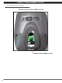
1.1 SERIAL NUMBER LOCATION
SERIAL NUMBER LOCATION
1
CHAPTER 1: SERIAL NUMBER LOCATION
1.1 SERIAL NUMBER LOCATION - CONTINUED
UNIVERSAL CONSOLE SERIAL NUMBER LOCATION
CONSOLE SERIAL NUMBER LOCATION
2
CHAPTER 2: IMPORTANT SAFETY INSTRUCTIONS
2.1 READ AND SAVE THESE INSTRUCTIONS
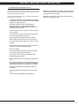
This Ascent Trainer is intended for commercial use. To ensure
your safety and protect the equipment, read all instructions before
operating the MATRIX Ascent Trainer.
CAUTION! If you experience chest pains, nausea, dizziness, or
shortness of breath, stop exercising immediately and consult
your physician before continuing. When using an electrical product, basic precautions should always be
followed including the following:
CAUTION! Any changes or modifications to this equipment
could void the product warranty. • A
n appliance should never be left unattended when plugged
in. Unplug the unit from the outlet when not in use and before
putting on or taking off any parts.
• T
his product must be used for its intended purpose
described in this service manual. Do not use other
attachments that are not recommend by the manufacturer.
Attachments may cause injury.
• T
o prevent electrical shock, never drop or insert any object
into any opening. • D
o not remove the console covers. Service should only be
done by an authorized service technician.
• N
ever operate the Ascent Trainer with the air opening
blocked. Keep the air opening clean, free of lint and hair.
• Do not carry this unit by it’s supply cord or use the cord as a handle. • C
lose supervision is necessary when the Ascent Trainer is
used by or near children or disable persons.
• Do not use outdoors. • D
o not operate where aerosol (spray) products are being
used or when oxygen is being administered.
• T
o disconnect, turn all controls to the off position, then
remove the plug from the outlet.
• Connect this Ascent Trainer to a properly grounded outlet only.
• D
o not use the equipment in any way other than designed or
intended by the manufacturer. It is imperative that all Matrix
Fitness Systems equipment is used properly to avoid injury.
• Keep hands and feet clear of moving parts at all times to avoid injury.
• Unsupervised children must be kept away from this equip
ment.
• Do not wear loose clothing while on the equipment.
3
CHAPTER 2: IMPORTANT SAFETY INSTRUCTIONS
2.2 ELECTRICAL REQUIREMENTS
The Matrix Ascent Trainer can now be self powered, but it recommended that the 7xe version of the Ascent Trainer be plugged in. If the A7xe
is left in self powered mode, it will take approximately 30 seconds for the screen to load prior to every workout. It is recommended that the unit
be plugged in for at least 4 hours after initial installation to charge the battery prior to using the self powered feature. NOTE: If an add on TV
(using a bracket) or Virtual Active is added to the unit, it must be plugged in, or the TV or VA will not operate correctly. If the Ascent Trainer will
be plugged in, follow the requirements below.
MATRIX DEDICATED CIRCUIT/ELECTRICAL REQUIREMENT INFO
All Matrix Ascent Trainers require the use of a 15 amp or 20 amp “dedicated circuit,” with a non-looped (isolated) neutral/ground, for the power
requirement. Quite simply this means that each outlet you plug Ascent Trainers into should not have anything else running on that same circuit
besides other Ascent Trainers (up to 3 per 15 amp circuit and 4 per 20 amp circuit). The easiest way to verify this is to locate the main circuit
breaker box, and turn off the breaker(s) one at a time. Once a breaker has been turned off, the only thing that should not have power to it are
the Ascent Trainers in question. No lamps, vending machines, fans, sound systems, or any other item should lose power when you perform this
test.
Non-looped (isolated) neutral/grounding means that each circuit must have an individual neutral/ground connection coming from it, and terminating
at an approved earth ground. You cannot “jumper” a single neutral/ground from one circuit to the next.
In addition to the dedicated circuit requirement, the proper gauge wire must be used from the circuit breaker box, to each outlet that will have the
maximum number of units running off of it. If the distance from the circuit breaker box, to each outlet, is 100 ft or less, then 12 gauge wire may be
used. For any distance greater than 100 ft from the circuit breaker box to the outlet, 10 gauge wire must be used.
For your safety and Ascent Trainer performance, the ground on this circuit must be non-looped. Please refer to NEC article 210-21 and 210-23. Your
Ascent Trainer is provided with a power cord with a plug listed below and requires the listed outlet. Any alterations of this power cord could void
all warranties for this product. Multiple Ascent Trainers can be powered on one dedicated circuit. (3 units per 15 Amp and 4 units per 20 Amp
dedicated circuit.)
GROUNDING INSTRUCTIONS:
The Matrix Ascent Trainer must be grounded. If it should malfunction or break down, grounding provides a path of least resistance for electric
current to reduce the risk of electric shock. The Ascent Trainer is equipped with a cord having an equipment grounding conductor and a
grounding plug. The plug must be plugged into an appropriate outlet that is properly installed and grounded in accordance with all local codes
and ordinances. If the user does not follow these grounding instructions, the user could void the Matrix limited warranty.
DANGER: Improper connection of the equipment grounding conductor can result in the risk of electric shock. Check with a qualified electrician
if the user is in doubt as to whether the product is properly grounded. Do not modify the plug provided with the product if it will not fit the outlet,
have a proper outlet installed by an electrician
CONSOLE POWER
The Matrix Ascent Trainer console has a battery that makes it self powered. This means that even if the unit is not plugged in, the console
may still have power for up to 12 hours. If the console power needs to be reset or turned off, press and hold the CHANNEL UP and CHANNEL
DOWN keys for 3-5 seconds until the console turns off. The console power will also need to be reset if settings are changed in Manager,
Engineering, or Service Modes.
4
CHAPTER 3: PREVENTATIVE MAINTENANCE
3.1 RECOMMENDED CLEANING TIPS
Preventative maintenance and daily cleaning will prolong the life and
look of your MATRIX Ascent Trainer.
Please read and follow these tips.
• P
osition the equipment away from direct sunlight. The intense UV
light can cause discoloration on plastics.
• L
ocate your equipment in an area with cool temperatures and low
humidity.
• Clean with a soft 100% cotton cloth.
• C
lean with soap and water or other non-ammonia based all purpose cleaners.
• W
ipe foot pads, handles, heart rate grips, and handlebars clean
after each use.
3.2 CHECK FOR DAMAGED PARTS
DO NOT use any equipment that is damaged or has worn or broken
parts. Use only replacement parts supplied by Matrix Fitness
Systems.
MAINTAIN LABELS AND NAMEPLATES. Do not remove labels
for any reason. They contain important information. If unreadable or
missing, contact Matrix Fitness Systems for a replacement. 1-866693-4863, www.matrixfitness.com
MAINTAIN ALL EQUIPMENT Preventative maintenance is the key
to smooth operating equipment. Equipment needs to be inspected
at regular intervals. Defective components must be replaced
immediately. Improperly working equipment must be kept out of use
until it is repaired. Ensure that any person(s) making adjustments
or performing maintenance or repair of any kind is qualified to do
so. Matrix Fitness Systems will provide service and maintenance
training at our corporate facility upon request or in the field if proper
arrangements are made.
• D
o not pour liquids directly onto your equipment. This can cause
damage to the equipment and in some cases electrocution.
• Check pedal motion and stability.
• Adjust leveling feet when equipment wobbles or rocks.
• Maintain a clean area around equipment, free from dust and dirt.
5
CHAPTER 3: PREVENTATIVE MAINTENANCE
3.3 CARE AND MAINTENANCE INSTRUCTION
In order to maximize life span, and minimize down time, all MATRIX equipment requires regular cleaning, and maintenance items performed on
a scheduled basis. This section contains detailed instructions on how to perform these items, the frequency of which they should be done, and a
check list to sign off each time service is completed for a specific machine. Some basic tools and supplies will be necessary to perform these tasks
which include (but may not be limited to):
* Metric Allen wrenches
* #2 Phillips head screwdriver
* Adjustable wrench
* Torque wrench (capability to read foot lbs, and inch lbs)
* Lint free cleaning cloths
* Teflon based spray lubricant
* Mild, water soluble, detergent – such as “Simple Green”, or other Matrix approved product
* Teflon based spray lubricant such as “Super Lube”, or other Matrix approved product
* Vacuum cleaner with an extendable hose and crevasse tool attachment
Please find the worksheet sample for our equipment provided in this manual and make copies as needed. Keep them up to date as the required
service / maintenance items are performed. It is critical that you also log the accumulated (total) amount of miles or running hours on the equipment
each time service or maintenance is performed.
You may periodically see addendums to this document, as the Matrix Technical Support Team identifies items that require specific attention, the
latest version will always be available on the Matrix website, www.matrixfitness.com
DAILY MAINTENANCE ITEMS
1)
Clean the entire machine using water and mild detergent such as “Simple Green”, or other Matrix approved solutions (cleaning agents should
be alcohol and ammonia free). NOTE: Never spray cleaner directly onto the equipment, spray cleaner onto a cloth and then wipe the
equipment.
QUARTERLY MAINTENANCE ITEMS
1)
Check all connecting joint areas for tightness of bolt assemblies.
2)
Ensure that there is little, or no free play at all joint assemblies once bolts have been tightened. Installation of washer kits may be required
if free play does not come out from tightening bolts.
3)
Remove plastic covers, and lubricate the ball joint where the Link Arm and Handlebar join together. Use your finger to apply grease to the
ball bearing. Matrix recommends using Superlube brand grease with PTFE {Teflon} additive.
4)
Remove the shrouds, and lubricate the Acme screw on the incline motor (Matrix recommends using Superlube brand grease with PTFE
{Teflon} additive).
YEARLY MAINTENANCE ITEMS
1)
6
Remove the front round covers and check the belts for damage, alignment, and proper tension.
CHAPTER 3: PREVENTATIVE MAINTENANCE
3.4 TOUCH SCREEN CARE & CLEANING
TOUCH SCREEN CARE AND CLEANING
* The touch screen requires very little maintenance. We
recommend that you periodically clean the touch screen surface
with a dry soft cloth. If necessary, we recommend the usage of
Alcohol or Isopropyl Alcohol for difficult stains or sanitary purposes.
* It is very important to avoid using any other chemical on the
touch screen.
* Always dampen the cloth and clean the screen. Do not spray
the cleaning agent on the screen itself, the drips can seep into the
display or stain the bezel.
* After cleaning, make sure the surface is dry. There should not be
any left over solvent to seep into the display.
3.5 AUTO CALIBRATION PROCEDURE
AUTO CALIBRATION PROCEDURE
After initial installation or replacement of the incline motor, auto
calibration should be run.
1) Press ENTER, 2, 0, 0, 1, ENTER on the keypad to go into
Engineering Mode.
2) Press CALIBRATION on the display.
3) Press AUTO CALIBRATION on the display.
4) Press START on the display.
5) This will run the Auto Calibration. If the calibration passes, it will
say complete. Press the HOME key to return to the normal start
screen.
6) If the calibration does not pass, contact Matrix Customer
Technical Support at 866-693-4863 ext 3.
* It is very important to handle the touch screen with care. Do not
use excessive force when cleaning.
* Do not use any sharp materials to clean the touch screen
surfaces.
* Do not use high pressure air, water, or steam to clean the touch
screen surface.
7
CHAPTER 4: CONSOLE OVERLAY AND WORKOUT DESCRIPTION
4.1 CONSOLE DESCRIPTION
The A7xe has a fully integrated touch screen display. All information required for workouts is explained on screen. Exploration of the interface is
high encouraged. The information explaining how to program for various workouts will give an explanation about the contents of each screen on
the machine.
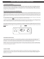
A7XE ENTERTAINMENT ZONE
IPOD®: Will take the user directly to the iPod screen to allow for iPod control and play list selection.
VOLUME UP / DOWN: Adjusts the volume output through the headphone jack of either the integrated console TV or the iPod output.
NUMBER KEYPAD: Allows for easy TV channel selections.
CHANNEL UP / DOWN: Allows for channel selection.
DISPLAY MODE: Allows user to cycle through console display options, iPod, TV, or profile display.
LAST CHANNEL: Allows the user to cycle between the current channel and the previous channel they were viewing.
8
CHAPTER 4: CONSOLE OVERLAY AND WORKOUT DESCRIPTION
4.2 WORKOUT SETUP STEPS
To set up a workout, press the touch screen over the program you
would like to use and then follow the prompts to begin your workout.
GO - Press to immediately begin a workout. Workout, resistance
level, and time will automatically go to default settings. Pressing GO
will not prompt user for age, weight, or level settings.
MANUAL - Manual allows the user to input more information while
defining their own workout. Calorie expenditure will be more accurate
when inputting information in Manual than by pressing GO.
FAT BURN - Fat burn is a level based program that is designed to
help users burn fat through various resistance level changes.
ROLLING HILLS - The Rolling Hills program is a level based
program that automatically adjusts the resistance level to simulate real
terrain.
INTERVALS - The Intervals program is a level based program that
automatically adjusts the resistance of the machine from low to high
intensity settings at regular intervals.
GLUTE TRAINING WORKOUT - This program was designed
to increase your range of motion and target the thighs and glutes.
By varying a high incline throughout the workout you can engage
significant glute recruitment and enjoy a great workout. You will
be asked to enter in a minimum resistance level and a maximum
resistance level. The maximum resistance is applied at your peaks
and the minimum resistance is applied in the valleys. Choose levels
that are appropriate for you. A great recommended starting point is a
Minimum Resistance Level of 1 and a Maximum Resistance Level of
8. After you are comfortable with this setting, try higher levels for both.
Incline levels cannot be adjusted during this workout as it is an incline
based workout.
FITNESS TEST -The Cooper Fitness Test measures cardiovascular
fitness and proves an estimated sub-maximal VO2 result. It is based on
power output according to ACSM standards and was developed by the
Cooper Institute© (www.cooperinstitute.org). User RPMs must remain
between 60-80 RPM during the test. The test will end when the user can
no longer maintain this speed. Use of a heart rate strap is optional but
provides more data.
The test starts at a low intensity level and gradually increases in intensity
(difficulty) every 2 minutes. As it increases, the user must maintain 60-80
RPM to advance to the next level. The test could take upwards of 30+
minutes for very fit individuals. Once the test ends a recovery period
(cool down) will begin and the user's results are calculated and displayed.
Results are based on the number of stages completed. Incline will not be
adjustable during the test.
STAGE COMPLETE:
1
2
3
4
5
6
7
8
9+
Well Below Average
Well Below Average
Below Average
Below Average
Average
Average
Above Average
Above Average
Well Above Average
CONSTANT WATTS - Constant Watts is a unique program that
allows you to vary your cadence or RPM and the Ascent Trainer's
resistance level will adjust accordingly to your selected goal. The quicker
you pedal, the less resistance for the goal selected.
TARGET HEART RATE - The Matrix Ascent Trainer comes
with standard digital contact heart rate sensors and are POLAR
telemetry compatible. The heart rate control workout mode allows
the user to program their desired heart rate zone, and the Ascent
Trainer will automatically adjust the level based upon the user's heart
rate. The heart rate zone is calculated using the following equation:
(220-Age)8%=target heart rate zone. The user must wear a POLAR
telemetric strap or continually hold onto the contact heart rate grips for
this workout.
Locate the metal sensors on the handlebars of the Ascent Trainer.
Notice that there are two separate pieces of metal on each grip.
You must be making contact with both pieces of each grip to get
an accurate heart rate reading. You can grab these sensors in any
program to view your current heart rate.
9
CHAPTER 5: MANAGER MODE
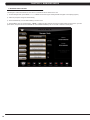
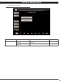
5.1 MANAGER MODE OVERVIEW
The Manager's Custom Mode allows the club owner to customize the Ascent Trainer for the club.
1) To enter Manager Mode, press ENTER, 1, 0, 0, 1, ENTER on the lower keypad. Manager Mode will appear on the display (Figure A).
2) Follow the prompts to change the desired setting.
3) Press the ENTER key once the desired setting is correct to save.
4) Press HOME to return to normal operation. NOTE: If a setting has been changed, the unit and console power should be reset. Cycle the
power switch, and press and hold the CHANNEL UP and CHANNEL DOWN keys for 3-5 seconds to reset the console power.
FIGURE A
10
CHAPTER 5: MANAGER MODE
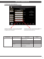
5.2 MANAGER MODE - SERIAL NUMBER TAB
A7xe-02-C or A7xe-01-C - If the unit has the old MMM
board, the CSafe Model should be set for Off (even if
the MMM console is replaced).
MANAGER MODE
About
FUNCTION & DEFAULTS
A7xe-03-C or A7xe-04 - If the unit has the LMM board
or the unit is the new model with 1 lift motor, the
CSafe Model should be set for On.
DESCRIPTIONS
MODIFIED
Serial Number
This option displays the serial number of the
platform and console. See Service Mode to
edit the serial numbers.
Cannot be modified.
Accumulated Distance
Total distance on the unit since production.
Cannot be modified.
Accumulated Time
Total time on the unit since production.
Cannot be modified.
Software Versions
Software version.
Cannot be modified.
Out of Order
Default: Off
This option allows the club to show the unit
"out of order" if an error is present.
On / Off
CSafe Model Default: On
This option controls whether the console is
Fitlinxx compatible.
On / Off
11
CHAPTER 5: MANAGER MODE
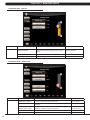
5.3 MANAGER MODE - TIME TAB
MANAGER MODE
Time
FUNCTION & DEFAULTS
DESCRIPTIONS
MODIFIED
Maximum Time
Default: 60 Minutes
This option allows the club to set the maximum
workout duration limits during peak and non peak
hours.
Maximum: 99 Minutes
Minimum: 5 Minutes
Default Time Default: 30 Minutes
This option controls the default program time.
Maxi: Max Time Min: 5 Minutes
Pause Time Default: 5 Minutes
This option controls the default pause time.
Max: 10 Min Min: 1 Minute
5.4 MANAGER MODE - DEFAULTS TAB
12
MANAGER MODE
FUNCTION & DEFAULTS
Defaults
Default Level Default: 1
This option controls the default program level.
Max: 1 Min: 20
Default Age Default: 30
This option controls the default user's age used in the target HR
calculations.
Max: 100 Min: 10
Default Weight
Default: 150 lbs / 68 kg
This option controls the default weight used in the calorie
calculations. Displayed in pounds or kilograms.
Max: 400 lbs / 182 kg
Min: 50 lbs / 22 kg
Gender Default: Male
Setting the user as Male or Female.
Male or Female
Key Sound Default: Yes
This option allows different sounds to be chosen for the keypad.
Yes or No
DESCRIPTION
MODIFIED
CHAPTER 5: MANAGER MODE
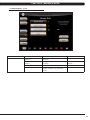
5.5 MANAGER MODE - TV TAB
MANAGER MODE
TV
FUNCTION & DEFAULTS
DESCRIPTIONS
MODIFIED
Default Channel
Default: 3
This option controls the default TV channel
on start up.
Channels 1-999
Default Volume
Default: 5
This option controls the default TV volume
on start up.
Maximum: 17
Minimum: 1
Tuner Available Default: Yes
This option controls the default TV function.
Yes or No
Setup
This option is used to set the TV tuner
function. Press the "-: key to enter this
function.
13
CHAPTER 5: MANAGER MODE
5.6 MANAGER MODE - LANGUAGE TAB
MANAGER MODE
Language
LANGUAGE
English
FUNCTION & DEFAULTS
Select default language.
FLAG
UNIT
Mile
LANGUAGE
Spanish
14
MODIFIED
FLAG
UNIT
KM
LANGUAGE
Chinese
KM
Mile
German
DESCRIPTIONS
This option allows the user to select a flag for a
specific language.
KM
Dutch
KM
KM
Italian
KM
KM
Japanese
KM
N/A
FLAG
UNIT
KM
KM
Portuguese
KM
KM
French
KM
CHAPTER 5: MANAGER MODE
5.7 MANAGER MODE - OTHER TAB
ENGINEERING MODE
Other
FUNCTION & DEFAULTS
DESCRIPTIONS
MODIFIED
Asset Management
Default: Off
This option allows fitness clubs to collect workout
data to a PC.
On or Off
Virtual Active
Default: Off
This option controls the Virtual Active function.
On or Off
15
CHAPTER 6: ENGINEERING MODE
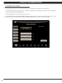
6.1 ENGINEERING MODE OVERVIEW
The Engineering Mode allows the club owner to keep track of the technical settings and error history for the Ascent Trainer.
1) To enter Engineering Mode, press ENTER, 2, 0, 0, 1, ENTER on the lower keypad. Engineering Mode will appear on the display (Figure A).
2) Follow the prompts to change the desired setting.
3) Press the ENTER key once the desired setting is correct to save.
4) Press HOME to return to normal operation. NOTE: If a setting has been changed, the unit and console power should be reset. Cycle the
power switch, and press and hold the CHANNEL UP and CHANNEL DOWN keys for 3-5 seconds to reset the console power.
FIGURE A
16
CHAPTER 6: ENGINEERING MODE
6.2 ENGINEERING MODE - CALIBRATION TAB
ENGINEERING MODE
Calibration
FUNCTION & DEFAULTS
DESCRIPTIONS
MODIFIED
Auto Calibration
This option calibrates the elevation parameters.
RPM Low Limit Charge:
Default: 10
This option controls the RPM low limit to iPod
charge.
Range: 0 - 255
RPM Low Limit Resistance
Default: 10
This option control the RPM low limit to show
resistance.
Range: 0 - 255
Default Incline %
Default: 10%
Starting incline level at each program start.
Range: 0% - 100%
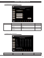
6.3 ENGINEERING MODE - STATISTICS TAB
ENGINEERING MODE
Statistics
FUNCTION & DEFAULTS
DESCRIPTIONS
This option displays the workout history.
MODIFIED
N/A
17
CHAPTER 6: ENGINEERING MODE
6.4 ENGINEERING MODE - ERRORS TAB
ENGINEERING MODE
FUNCTION & DEFAULTS
Errors
DESCRIPTIONS
This option displays the error code
history.
MODIFIED
N/A
6.5 ENGINEERING MODE - CLUBS TAB
ENGINEERING MODE
FUNCTION & DEFAULTS
Clubs
Default: MATRIX
18
DESCRIPTIONS
This option allows the club to select a screen
header from a list.
MODIFIED
N/A
CHAPTER 6: ENGINEERING MODE
6.6 ENGINEERING MODE - CLUB ID TAB
ENGINEERING MODE
FUNCTION & DEFAULTS
Club ID
DESCRIPTIONS
This option records the Club ID of
the fitness facility.
MODIFIED
N/A
6.7 ENGINEERING MODE - END POINTS TAB
ENGINEERING MODE
End Points
FUNCTION & DEFAULTS
DESCRIPTIONS
MODIFIED
Tune Incline 1 Top: Top: 2.0
Sets the maximum end incline for incline motor 1.
Top: 0.1 - 25.5
Tune Incline 1 Bottom: Bottom: 2.0
Sets the minimum end incline for incline motor 1.
Bottom: 0.1 - 25.5
Tune Incline 2 Top: Top: 2.0
Sets the maximum end incline for incline motor 2.
Top: 0.1 - 25.5
Tune Incline 2 Bottom: Bottom: 2.0
Sets the minimum end incline for incline motor 2.
Bottom: 0.1 - 25.5
19
CHAPTER 7: SERVICE MODE
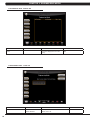
7.1 SERVICE MODE OVERVIEW
The Service Mode allows an authorized service provider to test and store information on the Ascent Trainer.
1) To enter Service Mode, press ENTER, 3, 0, 0, 1, ENTER on the lower keypad. Service Mode will appear on the display (Figure A).
2) Follow the prompts to change the desired setting.
3) Press the ENTER key once the desired setting is correct to save.
4) Press HOME to return to normal operation. NOTE: If a setting has been changed, the unit and console power should be reset. Cycle the
power switch, and press and hold the CHANNEL UP and CHANNEL DOWN keys for 3-5 seconds to reset the console power.
FIGURE A
20
CHAPTER 7: SERVICE MODE
7.2 SERVICE MODE - SETUP TAB
A7xe-02 - This setting is for non-self powered frames (A5x-02-F).
A7xe-03 - This setting is for self powered frames (A5x-03-F).
A7xe-04 - This setting is for the new style Ascent Trainer (A5x-04-F). This setting should be used for the current model.
SERVICE MODE
Setup
FUNCTION & DEFAULTS
DESCRIPTIONS
Machine Type: Default: Ascent Trainer
This option selects the current model.
Serial Number
This option displays the serial number of the console and frame.
Accumulated Distance
This option displays the accumulated workout distance since production.
Accumulated Time
This option displays the accumulated workout time since production.
Show Service on Boot
Factory Setting Only.
21
CHAPTER 7: SERVICE MODE
7.3 SERVICE MODE - TEST TAB
A7xe-02 Keypad - Old keypad - Includes
Quick Start Key
A7xe-03 Keypad - New keypad - Does NOT
Include Quick Start Key
SERVICE MODE
Test
22
FUNCTION & DEFAULTS
DESCRIPTIONS
Keypad
This option is for a keypad test.
Touch Calibration
This option starts a touch calibration. Follow the
cross mark moving across the screen and touch.
After testing 5 positions, touch the center to exit
the test.
Keypad Type Default: No Quick Start
This option sets the keypad type for the console.
Radio Test
This option will test the radio signal.
CHAPTER 7: SERVICE MODE
7.4 SERVICE MODE - LOG TAB
SERVICE MODE
FUNCTION & DEFAULTS
Log
DESCRIPTIONS
This option allows the club to record key
components replacement history.
7.5 SERVICE MODE - DATE & TIME TAB
SERVICE MODE
FUNCTION & DEFAULTS
Date & Time
DESCRIPTIONS
This option sets the current date and time of the
machine.
23
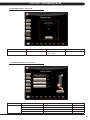
CHAPTER 8: TROUBLESHOOTING
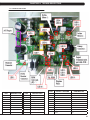
8.1 ELECTRICAL DIAGRAMS
24
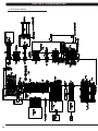
CHAPTER 8: TROUBLESHOOTING
8.1 ELECTRICAL DIAGRAMS - CONTINUED
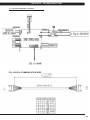
P21 - DIGITAL COMMUNICATION WIRE
25
CHAPTER 8: TROUBLESHOOTING
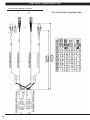
8.1 ELECTRICAL DIAGRAMS - CONTINUED
P25 - Hand Pulse Connecting Cable
26
CHAPTER 8: TROUBLESHOOTING
8.2 LCB ERROR INDICATORS
LED
LED
DESCRIPTION
LED
DESCRIPTION
LED 4
PULSES / SECOND
DESCRIPTION
2 times
Set for Self Powered System
1 time
Set for AC Plug In System
2 times
Class B Error
1 time
Burn In
0.5 times
Class A Error
2 times
Class C Error
LED 1
Generator RPM
LED 10
Incline 1 Rearward
LED 2
AC Plug In
LED 11
Incline 2 Rearward
LED 3
Vcc (5V)
LED 12
Charge
LED 4
System Status
LED 13
Discharge
LED 5
Error Status
LED 14
12V / 6A (main power)
LED 6
Error Status
LED 15
Console Power
0.5 times
Burn In
LED 7
Resistance
LED 16
E_RPM (external)
Bright
NO Resistance Offset.
LED 8
Incline 1 Forward
LED 17
15V / 8A (charge power)
Bright
No Use
LED 9
Incline 2 Forward
LED 18
Cool Fan
Pulse
Use
LED 5
LED 6
LED 16
27
CHAPTER 8: TROUBLESHOOTING
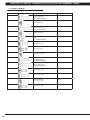
8.3 CONSOLE ERROR CODES
CODE
28
DESCRIPTION
SOLUTION
0x0140
When the UCB implements an incline command, the incline has no
action for 5 seconds.
Replace the Incline Motor or LCB.
0x0142
The incline position has a difference of over 30% and is not reduced
within 3 seconds.
Look for misalignment of the Incline
Motor, replace if needed.
0x0145
Self powered units only - incline stops when the LCB battery
capacity is too low or the RPMs are not high enough (<70 RPM).
Replace the LCB.
0x0441
When the UCB implements a command, the LCB is not receiving.
Check the console cable connections,
update the LCB software, or replace the
LCB or UCB as needed.
0x01A0
Left incline motor disconnected for 3 seconds.
Check the connection of the incline
motor cables at the LCB. Replace the
incline motor or LCB as needed.
0x01A1
Incline calibration is over 80 seconds or does not complete.
Replace the LCB or Incline Motor
0x01A7
The incline is short circuited or over current.
Look for misalignment of the Incline
Motor, replace if needed.
0x01AC
Generator or resistor has an open circuit, short circuit, or the current
is over 3.7 Amps for 1 second.
Check the connection of the Generator
and resistor, replace the generator or
resistor as needed.
0X01AF
The power resistor is disconnected.
Check the connection of the resistor at
the LCB. Replace the LCB if needed.
0x01B2
The incline motor has no action or current.
Check the fuse of the LCB, if blown,
replace the LCB. If the fuse is ok, run
auto calibration.
0x01AE
Battery over charge current or battery short circuit.
Replace the LCB.
0x0201
LCB battery low voltage (battery voltage < 11.2V).
Plug in the machine for AC charge.
Temporarily stop using incline.
0x0247
LCB fail (flash data error).
Replace the LCB.
0x0248
Battery disconnection or fail (the battery voltage is less than 8V)..
Check that the battery is connected. If
it is, replace the battery.
0x02AB
Machine type error.
Set the Machine Type and LCB.
0x02B4
Resistance type error.
Set the Machine Type and LCB.
0x03A5
Failed to load program.
Usually means the software file is
corrupt. Try upgrading the software or
replace the console if needed.
0x03A6
Failed to run program.
Usually means the software file is
corrupt. Try upgrading the software or
replace the console if needed.
0x03A7
Failed to load VA package files.
Check to see if the SD card is mounted
correctly and that there are no corrupt
video files present. Replace the VA
board if needed.
0x03A8
Machine type setting is not matching the LCB.
Set the correct Machine Type for the
console and LCB in Manager Mode.
0x04A0
If the LCB does not return a message to the UCB within 3 seconds.
Check the console cable connections,
replace the LCB or UCB as needed.
0x04B0
UCB no communication response.
Check the connections of the console
cable at the console and LCB. Replace
cc, console, or LCB as needed.
CHAPTER 8: TROUBLESHOOTING
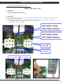
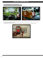
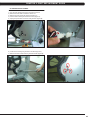
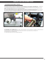
8.4 ERROR CODE TROUBLESHOOTING - 0140 / 01B2
ERROR CODE 0140 or 01B2
1) SYMPTOM:
a. 0140 - Incline motor operation has failed.
b. 01B2 - The incline motor has no action or current.
2) SOLUTION:
a. Run Auto Calibration (see Section 4.8), then check the LCB LEDs. If the incline LED is not a solid light (only one LED will show a solid
light at a time), replace the LCB (Figure A).
b. If the LCB incline LEDs are solid, use a multi meter to check the fuses. They should have an ohm reading of 0 (Figures B & C).
c. If the LCB incline LEDs are solid, and the fuses check out ok, run auto calibration.
- If calibration fails, replace the incline motor.
2
FIGURE A
FIGURE B
1
FIGURE C
29
CHAPTER 8: TROUBLESHOOTING
8.5 ERROR CODE TROUBLESHOOTING - 01A0
ERROR CODE 01A0
1) SYMPTOM:
a. 01A0 - Incline motor disconnected.
2) SOLUTION:
a.
b.
c.
d.
Check the Machine Type in Service Mode.
Check the connection of the incline motor at the LCB.
Run auto calibration (see Section 4.8).
If auto calibration fails, re-enter Engineering Mode and again go to Calibration.
- Measure the incline VR value (Figure A) by measuring across the Blue / Orange and Brown / Orange wiring in the incline motor wire
harness. The VR range should be 0.5k - 9.5k ohms (for example if the circuit is open or shorted). If the VR is outside of this range, replace the
incline motor.
e. If the incline motor does not resolve the issue, replace the LCB. NOTE: Run auto calibration if the incline motor or LCB is replaced.
FIGURE A
30
CHAPTER 8: TROUBLESHOOTING
8.6 TROUBLESHOOTING - NO POWER TO THE CONSOLE
NO POWER TO THE CONSOLE
1) SYMPTOM:
a. The unit is not getting power from the outlet.
b. The LCB is not getting power from the power receptacle.
c & d. The LCB LEDs are lit, but there is no power to the console.
2) SOLUTION:
a. Remove the front disk and check to see if LED15 is lit on the LCB. If it is not, verify power at the outlet. If the outlet is not outputting
120V, check the fitness room power.
- If LED 15 is still not lit after verifying the fitness room power, replace the power cord.
b. Check to see if LED 15 is lit on the LCB (Figure A).
- If LED 15 is not lit, check for incoming AC voltage at the LCB. Replace the power components as needed if the voltage is not present.
- Replace the LCB if all power components are ok and there is AC voltage to the LCB.
c. Check to see if LED D18 is lit on the upper control board (Figure B).
- If LED D18 is lit, check the switch on the IO board, it should be towards the right side (LCB_Power - Figure B).
- If LED D18 is not lit, check the console cable for connection at the LCB and console.
d. If LED D18 is not lit after checking the console cable connections, replace the console cable.
- If LED D18 is lit on the console, but there is still no power, replace the console.
FIGURE A
FIGURE B
31
CHAPTER 8: TROUBLESHOOTING
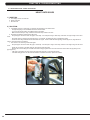
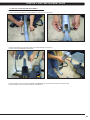
8.7 TROUBLESHOOTING - HEART RATE ISSUES
HEART RATE ISSUES
1) SYMPTOM:
a. The display is stuck on heart rate.
b. Erratic heart rate.
c. No heart rate.
2) SOLUTION:
a. If the display is stuck on heart rate, it is normally due to lighting in the workout area.
- Change the lighting in the immediate area of the Ascent Trainer.
- Try moving the Ascent Trainer to a different area in the facility.
- Make sure that nobody is using a telemetric heart rate strap / watch in the area.
b. Something is interfering with the heart rate signal.
- Verify the proper use of the heart rate grips / chest strap. For example if using a chest strap, make sure it is high enough on the user's
chest.
- Verify that nothing is touching the heart rate grips. For example, the safety key string or headphone wiring).
- There are some things that will interfere with heart rate signal. These include florescent lighting, electric dog fences, large electrical
motors, cell phone towers, and airports.
c. The console is not receiving a heart rate signal.
- Verify the proper use of the heart rate grips / chest strap. For example, if using a chest strap, make sure it is high enough on the user's
chest.
- Check the connection of the heart rate grip wiring at the heart rate board.
- Remove the screws holding the 2 halves of the heart rate grip together and check the connection of the heart rate grip wiring to the
grips (Figure A).
- If all wiring connections are good, replace the heart rate grips and / or the heart rate board.
- If the heart rate grips and / or the heart rate board do not resolve the issue, replace the console.
FIGURE A
32
CHAPTER 8: TROUBLESHOOTING
8.8 TROUBLESHOOTING - DISPLAY COLOR ISSUES
DISPLAY COLOR ISSUES
1) SYMPTOM:
a. The display colors are off or there are a rainbow of colors on the screen.
2) SOLUTION:
a. Check the console cable connections at the LCB and console.
b. check the LED display wire connection (Figure A).
- This wire connection should be taped in place. Add tape if needed.
- This wire should be tie strapped to the frame (Figure B). Add a tie strap if needed.
FIGURE A
FIGURE B
33
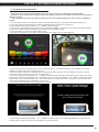
CHAPTER 8: TROUBLESHOOTING
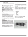
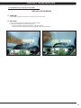
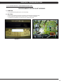
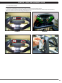
8.9 TV TROUBLESHOOTING - OVERVIEW
Sections 8.9 - 8.12 will assist with diagnosing problems with TV and entertainment related equipment sold
by Matrix FItness Equipment. The Matrix A7xe-04 Ascent Trainer includes an integrated TV that shows in the large display window. The TV is capable of being shown as a 7"
or 15" screen (Figures A & B). The console should be equipped with an entertainment keypad similar to Figure C.
FIGURE B
FIGURE A
FIGURE C
34
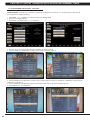
CHAPTER 8: TROUBLESHOOTING
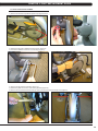
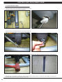
8.10 TV TROUBLESHOOTING - PICTURE FUZZY OR UNCLEAR
1) For a fuzzy or unclear picture, see the TV programming instructions in Section 10. If the TV is still fuzzy or unclear after programming:
a) Check the coax connection at the entertainment port (Figure A).
b) Remove the 5 screws holding the console to the console mast and check the coax connection at the console (Figure B).
FIGURE A
FIGURE B
c) Use a verified good piece of coax cable (a good coax cable will have a signal strength of 10hz or greater) to plug directly into the back
of the console bypassing the entertainment port. If this resolves the issue, replace the internal coax cable.
d) If plugging the coax cable into the back of the console does not resolve the issue, remove the console back and check the console
cable connection at the tuner (Figure C).
e) Check the internal cables and fitting inside your machine at the console and below the front shroud (Figure D). Make sure you have
no kinks, cuts, or poor connectors at the end of the cable. Fittings should have a clean flush connector with no stray aluminum strands touching
the center conductor. Replace any suspect cables.
FIGURE C
FIGURE D
f) If no damage can be found on the cables, fittings, or connectors, and hooking the coax directly to the back of the console does not
resolve the issue, replace the TV tuner.
35
CHAPTER 8: TROUBLESHOOTING
8.11 TV TROUBLESHOOTING - TV WILL NOT TURN ON
1) Remove the console back and check the electrical connections for the TV (Figures A & B).
FIGURE A
FIGURE B
2) After you have verified that all connects are secure, and the problem still persists, verify power at the outlet (Figure C). If the outlet is not
outputting 120V, check the fitness room power.
3) If internal electrical connections are good, and the outlet is outputting 120V, the issue is likely with the TV. Replace the console.
FIGURE C
36
CHAPTER 8: TROUBLESHOOTING
8.12 TV TROUBLESHOOTING - ENTERTAINMENT KEYPAD ISSUES
ENTERTAINMENT KEYPAD IS NOT WORKING
1) SYMPTOM:
a. The entertainment keypad (Figure A) is not responding.
2) SOLUTION:
a. Remove the console and check the connection of the entertainment keypad (Figure B).
b. If the entertainment keypad cable is pinched, kinked, or cut replace the keypad.
c. If replacing the keypad does not resolve the issue, replace the console.
FIGURE A
FIGURE B
37
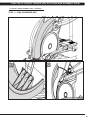
CHAPTER 9: PART REPLACEMENT GUIDE
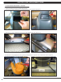
9.1 FRONT DISK REPLACEMENT
1) Remove the center cover by turning it counter clockwise (Figures A & B).
FIGURE A
FIGURE B
2) Remove the 3 screws holding the disk to the axle (Figure C).
3) Remove the disk (Figure D).
FIGURE C
FIGURE D
4) Reverse Steps 1-3 to install a new disk. NOTE: The 3 screws removed in Step 2 should be torqued to 25 N-m.
38
CHAPTER 9: PART REPLACEMENT GUIDE
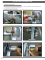
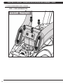
9.2 FRONT SHROUD REPLACEMENT
1) Remove the link arm and pedal arm plastic caps (Figures A & B).
FIGURE A
FIGURE B
2) Detach the dual action handlebar from the link arm (Figure C).
3) Secure the handlebar so that it is out of the way (Figure D).
FIGURE C
FIGURE D
4) Remove the front disks as outlined in Section 9.1.
5) Detach the pedal arm from the crank bearing assembly (Figure E).
6) Remove the 2 screws that hold the front top cover to the frame and remove the top cover (Figure F).
FIGURE E
FIGURE F
39
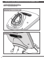
CHAPTER 9: PART REPLACEMENT GUIDE
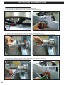
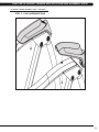
9.2 FRONT SHROUD REPLACEMENT - CONTINUED
7) Pull out the rubber tray from the cup holder plastic (figure G). 8) Remove the 2 screws to disassemble the cup holder plastic and remove it from the unit (Figure H).
FIGURE G
FIGURE H
9) Remove the 2 screws to disassemble and remove the middle stabilizer sweat cover (Figures I & J).
FIGURE I
FIGURE J
10) Remove the 1 screw (exposed when the cup holder is removed) holding the orange slot cover to the frame and remove it (Figure K).
11) Remove all of the cables from the front shrouds (Figure L).
FIGURE K
40
FIGURE L
CHAPTER 9: PART REPLACEMENT GUIDE
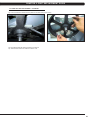
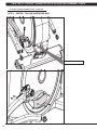
9.2 FRONT SHROUD REPLACEMENT - CONTINUED
12) Remove the 9 screws to detach the front shrouds from the frame (or each other) (Figure M).
13) Turn the crank to the slotted portion of the shroud (Figure N).
FIGURE M
FIGURE N
14) Remove the front shrouds for frame access (Figures O & P).
FIGURE O
FIGURE P
15) Reverse Steps 1-14 to install new shrouds. NOTE: The bolt / nut removed in Step 5 should be torqued to 70 N-m.
41
CHAPTER 9: PART REPLACEMENT GUIDE
9.3 LOWER CONTROL BOARD REPLACEMENT
1) Turn off the power and disconnect the cord from the machine.
2) Remove both front disks from the machine as outlined in Section 9.1.
3) Disconnect all wires from the LCB (Figure A).
FIGURE A
4) Remove the 2 screws holding the LCB to the frame (Figure B).
FIGURE B
6) Reverse Steps 1-4 to install a new LCB.
7) Test the Ascent Trainer for function as outlined in Section 9.22.
42
CHAPTER 9: PART REPLACEMENT GUIDE
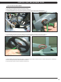
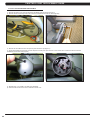
9.4 GENERATOR REPLACEMENT
1)
2)
3)
4)
5)
Turn off power and disconnect the cord from the machine.
R
emove the front disks as outlined in Section 9.1.
Remove the front shrouds as outlined in Section 9.2.
Cut the cable tie holding the cable to the frame (Figure A).
Unplug the power cable connector of the generator (Figure B).
FIGURE A
FIGURE B
6) Loosen the nut holding the generator to the frame (Figure C).
7) Remove the three screws from the generator bracket (Figure D).
FIGURE C
FIGURE D
43
CHAPTER 9: PART REPLACEMENT GUIDE
9.4 GENERATOR REPLACEMENT – CONTINUED
8) Remove the nut from the other side of the generator bracket (Figure E).
9) Loosen and remove the generator belt (Figure F).
FIGURE E
FIGURE F
10) Remove the generator from the frame.
11) Reverse Steps 1-10 to install a new generator. Re-install the belts as outlined in Section 9.5. NOTE: The 3 screws removed in Step 7
should be torqued to 8 N-m and the nut from Step 8 to 40 N-m.
12) Test the Ascent Trainer for function as outlined in Section 9.22.
44
CHAPTER 9: PART REPLACEMENT GUIDE
9.5 GENERATOR BELT REPLACEMENT
1) Turn off the power and disconnect the cord from the machine.
2) Remove the front disks from the machine as outlined in Section 9.1.
3) Remove the front shrouds as outlined in Section 9.2.
4) Remove the generator as outlined in Section 9.4.
5) To install a new belt, first put the belt installation tool on the pulley (Figure A). FIGURE A
6) Put the new belt on the installation tool (Figure B).
7) Turn the pulley until the belt is installed. Rotate the pulley at least 3 full rotations to insure that the belt is centered.
FIGURE B
8) Reverse Steps 1-4 to re-assemble the unit.
9) Test the Ascent Trainer for function as outlined in Section 9.22. .
45
CHAPTER 9: PART REPLACEMENT GUIDE
9.6 DRIVE BELT REPLACEMENT
1) Turn off the power and disconnect the cord from the machine.
2) Remove the front disks from the machine as outlined in Section 9.1.
3) Loosen the belt tension bolt on the left side of the tension pulley and rotate the pulley counter-clockwise until there is enough slack in the
belt to remove it (Figures A & B).
FIGURE A
FIGURE B
4) Install the replacement belt and reverse necessary steps to secure the assembly until the belt is tight. NOTE: Tighten the drive belt to 180
lbs. for a new belt, 150 lbs. for a used belt. The idler bolt should be torqued to 80 N-m.
5) Test the Ascent Trainer for function as outlined in Section 9.22.
46
CHAPTER 9: PART REPLACEMENT GUIDE
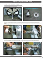
9.7 PULLEY AXLE SET REPLACEMENT
1)
2)
3)
4)
Turn off the power and disconnect the cord from the machine.
Remove both front disks from the machine as outlined in Section 9.1.
Loosen the belt tension bolt on the right side until there is enough slack to remove the drive belt (Figure A).
On the right side of the frame, remove the retaining clip that holds the pulley axle bearing into the frame (Figure B).
FIGURE A
FIGURE B
5) On the left side of the frame, remove the retaining ring that holds the pulley axle bearing into the frame (Figure C).
6) Remove the pulley axle set assembly from the frame. Clean any debris from the hole in the frame (Figure D).
FIGURE C
FIGURE D
7) Reverse Steps 1-6 to install a new pulley axle set. Rotate the pulley to make sure that the motion is smooth and that there is no wobbling to
one side. Re-install the belts as outlined in Sections 9.5 and 9.6.
8) Test the Ascent Trainer for function as outlined in Section 9.22.
47
CHAPTER 9: PART REPLACEMENT GUIDE
9.8 DRIVE AXLE SET REPLACEMENT
NOTE: A Matrix special tool is needed to correctly replace a drive axle. Order part # 0000094817 from Matrix CTS at 866-693-4863 ext 3. 1) Turn off the power and disconnect the cord from the machine.
2) Remove the front disks from the machine as outlined in Section 9.1.
3) Remove both belts as outlined in Sections 9.5 & 9.6.
4) On the left side of the frame, remove the retainer clip that holds the drive axle bearings in the frame (Figure A).
5) Install an M10 screw into the drive axle (Figure B).
FIGURE A
FIGURE B
6) Turn the screw until the head is close to the drive axle (Figure C).
7) Use a hammer to hit the screw until the drive axle assembly is loose in the frame, and remove it (Figure D).
FIGURE C
FIGURE D
8) Install the tool into the hole in the frame (Figure E).
9) Use a rubber mallet to hit the end of the tool until the bearing can be removed from the frame (Figure F).
FIGURE E
48
FIGURE F
CHAPTER 9: PART REPLACEMENT GUIDE
9.8 DRIVE AXLE SET REPLACEMENT - CONTINUED
10) The drive axle should have come with an iron plate installed (Figure G).
11) Assemble the Matrix tool as shown in Figure H.
FIGURE G
FIGURE H
12) Slide the drive axle assembly into the frame from the right side. Install the bearing cap portion of the tool into the left side of the frame
(Figure I).
13) Mount the other tool from Figure H behind the bearing cap portion of the tool. Use the M10 x 65L screw with a washer and a nut to attach the
tool to the drive axle (Figure J).
FIGURE I
FIGURE J
14) Turn the screw at least 4 full revolutions into the drive axle. Then turn the nut until it is close to the cup portion of the tool (Figure K).
15) Use a wrench to hold the screw, then turn the nut to pull the drive axle into the frame (Figure L).
FIGURE K
FIGURE L
49
CHAPTER 9: PART REPLACEMENT GUIDE
9.8 DRIVE AXLE SET REPLACEMENT - CONTINUED
16) Turn the nut until the iron plate is close to the frame on the right side (Figure M).
17) Remove the tools, then insert the bearing into the hole in the frame on the left side (Figure N).
FIGURE M
FIGURE N
18) Again use the M10 x 65L screw with a washer and a nut to attach the tool to the drive axle (Figure O).
19) Turn the screw at least 4 full revolutions into the drive axle. Then turn the nut until it is close to the cup portion of the tool (Figure P).
FIGURE O
FIGURE P
20) Use a wrench to hold the screw, then turn the nut to push the bearing into the hole in the frame (Figure Q).
21) Insert the retainer clip to hold the bearing in the frame (Figure R).
FIGURE Q
50
FIGURE R
CHAPTER 9: PART REPLACEMENT GUIDE
9.8 DRIVE AXLE SET REPLACEMENT - CONTINUED
22) Use a screwdriver to remove the iron plate from the drive axle (Figures S & T).
FIGURE S
FIGURE T
23) Re-install the belts as outlined in Sections 9.5 and 9.6.
24) Test the Ascent Trainer as outlined in Section 9.22.
51
CHAPTER 9: PART REPLACEMENT GUIDE
9.9 CRANK REPLACEMENT
1) Turn off the power and disconnect the cord from the machine.
2) Remove the front disks from the machine as outlined in Section 9.1.
3) Remove the screw from the crank (Figure A).
4) Insert an M10 screw (should be at least 40 long) into the crank hole. Then turn the screw until the crank can be separated from the axle
(Figure B).
FIGURE A
FIGURE B
5) Install the replacement crank. There should be a 4mm gap between the end of the drive axle shaft and the crank (Figure C).
FIGURE C
6) Install the crank screw. NOTE: This screw should be torqued to 80 N-m.
7) Reverse Steps 1-2 to re-assemble the unit.
52
CHAPTER 9: PART REPLACEMENT GUIDE
9.10 CONSOLE REPLACEMENT
1) Turn off the power and disconnect the cord from the machine.
2) R
emove the 5 screws that hold the console to the top of the console mast (Figure A).
3) Disconnect the console cable and other wiring and remove the console (Figure B).
FIGURE A
FIGURE B
4) Remove the 5 screws that hold the mounting plate to the console (Figure C).
FIGURE C
5) Attach the mounting plate to the new console.
6) Connect the wire connections to the new console.
7) Carefully push the wires into the console and mast until they are clear of the console / mast connection and attach the console to the mast
using the 5 screws removed in Step 2.
8) Test the Ascent Trainer for function as outlined in Section 9.22.
53
CHAPTER 9: PART REPLACEMENT GUIDE
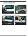
9.11 CONSOLE OVERLAYS & KEYPADS REPLACEMENT
1) Remove the console as outlined in Section 9.10.
2) Remove the back cover of the console (Figure A).
3) Unplug and remove the faulty overlay (Figure B).
FIGURE A
FIGURE B
4) Clean the console area with alcohol to remove any left over adhesive (Figure C).
5) Peel part of the protective film from the back of the overlay / keypad (Figure D).
FIGURE C
54
FIGURE D
CHAPTER 9: PART REPLACEMENT GUIDE
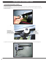
9.11 CONSOLE KEYPAD / OVERLAY REPLACEMENT - CONTINUED
6) Push the overlay / keypad ribbon cable through the hole in the console and plug it in (Figure E).
7) Match the overlay / keypad to the cutout in the console (Figure F).
FIGURE E
FIGURE F
7) Press down on the corners of the overlay / keypad to keep it in place. Then remove the protective film (Figure G).
8) Once the overlay / keypad is in the correct position, press down on it to adhere it in positions (Figure H).
FIGURE G
FIGURE H
9) Use the same procedure to replace any additional faulty overlays / keypads. NOTE: Overlays / keypads cannot be re-used.
55
CHAPTER 9: PART REPLACEMENT GUIDE
9.12 CONSOLE MAST HANDLEBAR REPLACEMENT
1) Turn off the power and disconnect the cord from the machine.
2) Remove the 4 bolts that hold the handlebar to the console mast (Figure A).
FIGURE A
4) Pull the handlebar away from the console mast to expose the HR grip wiring (Figure B).
5) Carefully remove the wires from inside the console mast until the connectors on the ends come free and disconnect (Figure C).
FIGURE B
FIGURE C
6) To install a new handlebar assembly, connect the new handlebar and carefully push the heart rate wires into the console mast.
7) Attach the new handlebar assembly to the console mast using the 4 screws removed in Step 3.
8) Test the Ascent Trainer for function as outlined in Section 9.22.
56
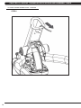
CHAPTER 9: PART REPLACEMENT GUIDE
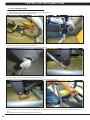
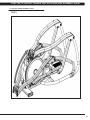
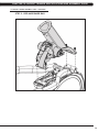
9.13 INCLINE MOTOR REPLACEMENT
1) Turn off the power and disconnect the cord from the machine.
2) Remove the front disks as outlined in Section 9.1.
3) Complete Steps 6-8 and 10 from Section 9.2 to remove the cupholder and top shrouds from the unit (the main side shrouds do not need to be
removed).
4) Disconnect the incline motor ground wire from the frame and disconnect the incline motor power wire (Figures A & B). If unsure if the incline
motor is the issue, plug in the new incline motor at this time to see if it is energized. If it is not, the issue is likely with the LCB.
FIGURE A
FIGURE B
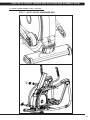
5) Remove the spring clip to separate the incline motor from the frame (Figure C).
6) Remove the incline motor by loosening the pivot bolts on each side (Figure D - NOTE: Figure D shows the unit with the shrouds removed for
clarity). NOTE: Prior to loosening the pivot bolts, secure the incline motor as it can fall once the pivot bolts are loosened.
FIGURE C
FIGURE D
57
CHAPTER 9: PART REPLACEMENT GUIDE
9.13 INCLINE MOTOR REPLACEMENT - CONTINUED
7) While the incline motor is out, the carriage rollers should be checked. Turn the rollers. The rollers should turn smoothly with only a small
amount of friction (Figure E).
8) If the rollers need to be adjusted, loosen the horizontal bolts simultaneously first, then adjust the roller friction by adjusting the vertical screws
simultaneously (Figure F).
FIGURE E
FIGURE F
9) Prepare the new incline motor for installation. The new incline motor should have the nut placed close to the end of the shaft (Figure G).
FIGURE G
58
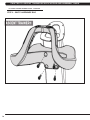
CHAPTER 9: PART REPLACEMENT GUIDE
9.13 INCLINE MOTOR REPLACEMENT - CONTINUED
10) Plug in the power wire of the new incline motor (with the motor still outside the unit). Plug in the unit. Press ENTER, 3, 0, 0, 1, ENTER to go
to Service Mode. Scroll with the LEVEL UP or DOWN keys until Service 6 is displayed. Press ENTER to start Auto Calibration.
11) Turn off power immediately when the new motor has been driven to the limit switch at the TOP of the incline range during Auto Calibration.
NOTE: You are stopping power when the unit is 1/2 way through calibration.
12) Push the carriage towards the rear of the unit. There should be a gap of 8mm (+/- 2mm) between the carriage and the frame. Use an 8mm
Allen wrench to maintain this spacing (Figure H - NOTE: Figure H shows a unit with the console mast removed for clarity).
13) Turn the nut on the incline motor until the screw holes in the nut line up with the screw holes on the carriage (Figure I). Tighten the screws
loosened in Step 6 to attach the incline motor nut to the carraige. Torque these screws to 25 N-m.
FIGURE H
FIGURE I
14) Plug in the unit. Allow the incline to reset.
15) Press ENTER, 3, 0, 0, 1, ENTER to go to Service Mode. Start Auto Calibration. Allow Auto Calibration to completely run. Make sure that the
incline motor carriage is not hitting the frame at the top or bottom of the movement. If any issues are seen, re-do Steps 10-13.
16) Reverse Steps 1-5 to re-assemble the unit.
17) Test the Ascent Trainer for function as outlined in Section 9.22.
59
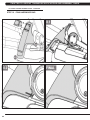
CHAPTER 9: PART REPLACEMENT GUIDE
9.14 DUAL ACTION HANDLEBAR REPLACEMENT
1) Remove the plastic cover where the dual action handlebar meets the link arm (Figure A).
2) Remove the bolt and bushings where the dual action handlebar and the link arm meet (Figure B).
FIGURE A
FIGURE B
3) Remove the two bolts that hold on the pivot cap and remove the cap (Figure C).
4) Unplug and separate the heart rate connector exposed once the pivot cap is removed. Then remove the 4 screws that hold the dual action
handlebar to the console mast (Figure D).
FIGURE C
5) Reverse steps 1-4 to install a new dual action handlebar.
6) Test the Ascent Trainer for function as outlined in Section 9.22.
60
FIGURE D
CHAPTER 9: PART REPLACEMENT GUIDE
9.15 FOOT PEDALS REPLACEMENT
1) P
ull up on and remove the rubber portion of the pedal (Figure A).
2) Remove the 4 screws that hold the plastic pedal to the foot plate (Figure B).
FIGURE A
FIGURE B
3) Remove the plastic foot pedal (Figure C).
FIGURE C
4) Clean the foot plate to remove any rubber or debris.
5) Reverse Steps 1-4 to install a new foot pedal.
6) Test the Ascent Trainer as outlined in Section 9.22.
61
CHAPTER 9: PART REPLACEMENT GUIDE
9.16 PEDAL ARM REPLACEMENT
1) Remove the plastic cover where the pedal arm attaches to the crank (Figure A).
2) Disconnect the pedal arm from the crank (Figure B).
FIGURE A
FIGURE B
3) Remove the plastic cap from the swing arm (Figure C).
4) Remove the bolt that holds the pedal and swing arms together (Figure D).
FIGURE C
FIGURE D
5) The swing arm can now be separate from the pedal arm (Figure E).
6) Remove the bolt that holds the link arm to the pedal arm and remove the pedal arm (Figure F).
FIGURE E
FIGURE F
7) Reverse Steps 1-5 to install a new pedal arm. NOTE: Torque the bolt removed in Step 4 to 80 N-m and the bolt / nut removed in Step 2 to 70
N-m.
8) Test the Ascent Trainer for function as outlined in Section 9.22.
62
CHAPTER 9: PART REPLACEMENT GUIDE
9.17 LINK ARM REPLACEMENT
1) Remove the plastic cover where the dual action handlebar meets the link arm (Figure A).
2) Remove the bolt and bushings where the dual action handlebar meets the link arm (Figure B).
FIGURE A
FIGURE B
3) Remove the bolt that holds the link arm to the pedal arm and remove the link arm (Figure C).
FIGURE C
4) Reverse Steps 1-3 to install a new link arm.
5) Test the Ascent Trainer for function as outlined in Section 9.22.
63
CHAPTER 9: PART REPLACEMENT GUIDE
9.18 SWING ARM REPLACEMENT
1) Remove the bolt from the upper pivot joint on the swing arm (Figure A).
2) Remove the plastic cap from the swing arm (Figure B).
FIGURE A
FIGURE B
3) Remove the bolt that holds the swing arm to the pedal arm (Figure C).
4) Take the bolt removed in Step 1 and turn it into the shaft (Figure D).
FIGURE C
FIGURE D
5) Use a mallet to hit the head of the bolt until the swing arm can be separate from the pedal arm, and remove the pedal arm (Figures E & F).
FIGURE E
FIGURE F
6) Reverse Steps 1-5 to install a new swing arm. NOTE: Torque the bolts removed in Steps 1 & 3 to 80 N-m when installing a new swing arm.
7) Test the Ascent Trainer for function as outlined in Section 9.22.
64
CHAPTER 9: PART REPLACEMENT GUIDE
9.19 VERTICAL STABILIZER ARM REPLACEMENT
1) Remove the bolt that holds the vertical stabilizer arm to the frame (Figures A & B).
FIGURE A
FIGURE B
2) Remove the bolt from the upper pivot joint of the vertical stabilizer arm (Figure C).
3) Remove the vertical stabilizer arm (Figure D).
FIGURE C
FIGURE D
4) Reverse Steps 1-3 to install a vertical stabilizer arm. NOTE: Tighten the bolt removed in Step 2 to 80 N-m torque.
5) Test the Ascent Trainer for function as outlined in Section 9.22.
65
CHAPTER 9: PART REPLACEMENT GUIDE
9.20 INCLINE ARM COVER REPLACEMENT
1) Remove the screw that holds the plastic cover on the arm (Figures A & B).
FIGURE A
FIGURE B
2) Remove the incline arm cover (Figure C).
FIGURE C
3) Reverse Steps 1-2 to install a new incline arm.
66
CHAPTER 9: PART REPLACEMENT GUIDE
9.21 HANDLEBAR SERVICE
1) All items on the handlebar are removed using a Phillips screwdriver from the underside of the bar.
2) Once the screws are removed, lift the part carefully, then disconnect any wire connections to fully remove the part. This includes any
resistance & elevation buttons and heart rate grip plates (Figures A - D).
FIGURE A
FIGURE B
FIGURE C
FIGURE D
67
CHAPTER 9: PART REPLACEMENT GUIDE
9.22 TESTING THE ASCENT TRAINER
ONCE THE UNIT OR REPLACEMENT PART IS FULLY INSTALLED AND ASSEMBLED AND
PROPERLY PLACED ON THE FLOOR, USE THE FOLLOWING INSTRUCTIONS TO TEST
THE MACHINE:
1) Enter Service Mode (ENTER, 3, 0, 0, 1, ENTER) and input the serial number of the console. Also set the Machine Type (See Section 7.2)
and Keypad (See Section 7.3) and verify that the Date and Time are correct (See Section 7.5). NOTE: The console and unit power must be
reset for some changes to go into affect. Cycle the power switch and press and hold the CHANNEL UP and CHANNEL DOWN keys for 3-5
seconds to reset the console power.
2) Enter Manager Mode (ENTER, 1, 0, 0, 1, ENTER) and turn on or off Asset Management or Virtual Active depending on whether the club has
these functions. NOTE: The console and unit power must be reset for some changes to go into affect. Cycle the power switch and press and
hold the CHANNEL UP and CHANNEL DOWN keys for 3-5 seconds to reset the console power.
3) Without hitting start or entering any exercise modes, stand on the machine and hold the handlebars while initiating movement to simulate
exercising. While moving listen for any odd noises or squeaks.
4) After stopping movement, press the green GO key and begin using the machine.
5) Grasp the hand grips to check for proper heart rate response.
6) Press the LEVEL UP and DOWN keys on the console to make sure resistance is fully functional.
7) Press the ELEVATION UP and DOWN keys (fully incline and decline the machine) to make sure the incline motor function is fully operational.
8) If the Ascent Trainer has had an incline motor replaced, or if this is the initial installation, calibrate the lift motor (see Section 3.5).
68
CHAPTER 10: ASCENT TRAINER SPECIFICATIONS AND ASSEMBLY GUIDE
10.1 ASCENT TRAINER SPECIFICATIONS
FEATURES
Stride Length
20-24"
Incline Range
24% - 54% (15° range)
Contact and Telemetric Heart Rate Sensors
Yes
Cushioned Footpads
Yes - Premium
Q-Factor
2.5"
Handlebar Design
Multi-position dual action and ergo bend stationary.
Thumb Switch Controls
Yes
RESISTANCE SYSTEM
Technology
Generator
Power Requirements
Self Powered - Powered 100V - 240V - 50 / 60 HZ AC
Minimum Watts
56 Self Powered
Minimum RPM
10 Powered / 25 Non-Powered
CONSOLE
Display Type
15" Touch Screen
Display Feedback
Time, Distance, Calories, Calories per hour, Speed, Incline, Heart
Rate, METs, Watts, Level, RPM, Dynamic Profile Display, Static
Profile Display
User Defined Multi Language Display
Yes - English, German, French, Italian, Spanish, Dutch, Portuguese,
Chinese, Japanese, Korean, Swedish, Finnish, Russian, Arabic
Resistance Levels
25
Workouts
Manual, Rolling, Intervals, Fat Burn, Glute Training, Fitness Test,
Target HR, Constant Watts
CSafe, Fitlinxx Ready
Yes
Netpulse Ready
No
Fit Touch Technology
Yes
On the Fly Program Change
Yes
Integrated Vista Clear™ Digital Ready Television
Yes - 15" Screen Size
Fitconnexion™ Ready
No
Wireless Data Transmitter
Yes
IPod Compatible
Yes
Nike+ IPod Compatible
Yes
Personal Fan
Yes
USB Workout Tracking
Yes - Via www.livestrong.com
Virtual Active™ Compatible
Yes
TECHNICAL DATA
Overall Dimensions (L x W x H)
81 x 34 x 79" (1780 x 742 x 1740mm)
Maximum User Weight
400 lbs / 181.4 kg
Unit Weight
445 lbs / 202.7 kg
Shipping Weight
476 lbs / 216.5 kg
69
CHAPTER 10: ASCENT TRAINER SPECIFICATIONS AND ASSEMBLY GUIDE
10.2 ASSEMBLY HARDWARE
QUANTITY
70
SKETCH
DESCRIPTION
PACKAGE COLOR
4
SOCKET HEAD CAP SCREW
(M10 X 1.5P X 25L)
10.9 GRADE MINIMUM
RED (2 BAGS)
4
FLAT WASHER
(10.2 X 20 X 2.0T)
RED (2 BAGS)
1
SOCKET HEAD CAP SCREW
(M10 X 1.5P X 100L)
12.9 GRADE MINIMUM
GREEN
2
FLAT WASHER
(10.2 X 20 X 2.0T)
GREEN
1
HEX NUT
(M10)
10.9 GRADE MINIMUM
GREEN
5
SCREW
(M5 X 0.8P X 10L)
YELLOW
2
SCREW
(M5 X 0.8 X 12L)
BLACK (2 BAGS)
4
SPRING WASHER
(8.2 X 15.4 X 2.0T)
BLACK (2 BAGS)
4
SOCKET HEAD CAP SCREW
(M8 X 1.25P X 20L)
10.9 GRADE MINIMUM
BLACK (2 BAGS)
1
SOCKET HEAD CAP SCREW
(M8 X 1.25P X 45L)
10.9 GRADE MINIMUM
BLUE (2 BAGS)
3
SCREW
(M5 X 0.8P X 16L)
BLUE (2 BAGS)
4
SOCKET HEAD CAP SCREW
(M8 X 1.25P X 25L)
WHITE
4
SPRING WASHER
(8.2 X 13.5 X 2.0T)
WHITE
12
SCREW
(M5 X 0.8P X 16L)
PINK
CHAPTER 10: ASCENT TRAINER SPECIFICATIONS AND ASSEMBLY GUIDE
10.3 ASCENT TRAINER ASSEMBLY STEPS
STEP 1
71
CHAPTER 10: ASCENT TRAINER SPECIFICATIONS AND ASSEMBLY GUIDE
10.3 ASCENT TRAINER ASSEMBLY STEPS - CONTINUED
STEP 2 - RED HARDWARE BAG
72
CHAPTER 10: ASCENT TRAINER SPECIFICATIONS AND ASSEMBLY GUIDE
10.3 ASCENT TRAINER ASSEMBLY STEPS - CONTINUED
STEP 3 - PINK HARDWARE BAG
73
CHAPTER 10: ASCENT TRAINER SPECIFICATIONS AND ASSEMBLY GUIDE
10.3 ASCENT TRAINER ASSEMBLY STEPS - CONTINUED
STEP 4 - GREEN / YELLOW HARDWARE BAG
Torque this bolt to 80 N-m.
74
CHAPTER 10: ASCENT TRAINER SPECIFICATIONS AND ASSEMBLY GUIDE
10.3 ASCENT TRAINER ASSEMBLY STEPS - CONTINUED
STEP 5 - RED HARDWARE BAG
75
CHAPTER 10: ASCENT TRAINER SPECIFICATIONS AND ASSEMBLY GUIDE
10.3 ASCENT TRAINER ASSEMBLY STEPS - CONTINUED
STEP 6
76
CHAPTER 10: ASCENT TRAINER SPECIFICATIONS AND ASSEMBLY GUIDE
10.3 ASCENT TRAINER ASSEMBLY STEPS - CONTINUED
STEP 7 - BLUE / BLACK HARDWARE BAG
77
CHAPTER 10: ASCENT TRAINER SPECIFICATIONS AND ASSEMBLY GUIDE
10.3 ASCENT TRAINER ASSEMBLY STEPS - CONTINUED
STEP 8 - WHITE HARDWARE BAG
78
CHAPTER 10: ASCENT TRAINER SPECIFICATIONS AND ASSEMBLY GUIDE
10.3 ASCENT TRAINER ASSEMBLY STEPS - CONTINUED
STEP 9 - PINK HARDWARE BAG
79
CHAPTER 10: ASCENT TRAINER SPECIFICATIONS AND ASSEMBLY GUIDE
10.3 ASCENT TRAINER ASSEMBLY STEPS - CONTINUED
STEP 10 - PINK HARDWARE BAG
80
CHAPTER 10: ASCENT TRAINER SPECIFICATIONS AND ASSEMBLY GUIDE
10.3 ASCENT TRAINER ASSEMBLY STEPS - CONTINUED
STEP 11 - PINK HARDWARE BAG
81
CHAPTER 10: ASCENT TRAINER SPECIFICATIONS AND ASSEMBLY GUIDE
10.3 ASCENT TRAINER ASSEMBLY STEPS - CONTINUED
STEP 12 - PINK HARDWARE BAG
82
CHAPTER 10: ASCENT TRAINER SPECIFICATIONS AND ASSEMBLY GUIDE
10.4 STABILIZING THE ASCENT TRAINER
STABILIZING THE MATRIX A7XE-04 ASCENT TRAINER
The Matrix Ascent Trainer should be level for optimum use. Once you have placed your unit where you intend to use it, raise or lower one or
both of the adjustable levelers located on the bottom of the frame. Use a 6mm Allen wrench through the access hole at the rear hinge joint on
both sides (Figure A).
FIGURE A
83
CHAPTER 10: ASCENT TRAINER SPECIFICATIONS AND ASSEMBLY GUIDE
10.5 TV PROGRAMMING INSTRUCTIONS
Once the cardio equipment has been installed, and proper power and cable wiring is provided, The Television must be programmed to the club's
channels and settings.
Auto Scan - An auto scan will search for channel signals from the coax cable. It will tune in all channels that provide a signal.
1. Press ENTER, 1, 0, 0, 1, ENTER on the number keypad to enter Manager Mode.
2. Press TV on the display (Figure A).
3. Press SETUP on the display (Figure B). A TV will appear.
FIGURE A
FIGURE B
4. Press the - key on the number keypad and a Menu will appear on the TV (Figure C). NOTE: Once the Menu is present on the screen, the
following buttons must be pressed quickly, or the Menu will minimize after 5 seconds of no key strokes.
5. Use the VOLUME UP or DOWN keys to move horizontally in the Menu and the CHANNEL UP and DOWN keys to move vertically.
6. Use the VOLUME UP or DOWN keys to scroll the cursor to Channel on the top right of the Menu (Figure D).
FIGURE C
FIGURE D
7. Use the CHANNEL UP or DOWN keys to scroll down to Auto Scan, then press the VOLUME UP or DOWN keys to enter the Channel Scan
sub-menu (Figure E).
8. Use the CHANNEL UP or DOWN keys to scroll to Start To Scan, then press the VOLUME UP or DOWN keys to start the channel scan
(Figure F).
FIGURE E
84
FIGURE F
CHAPTER 10: ASCENT TRAINER SPECIFICATIONS AND ASSEMBLY GUIDE
10.5 TV PROGRAMMING INSTRUCTIONS - CONTINUED
Auto Scan (continued):
9. If the channels are not coming in clearly after a channel scan (or if only some channels come in), follow Steps 4-7 to enter the Auto Scan
sub-menu. Use the VOLUME UP or DOWN keys to change the Cable System to match the club's incoming frequency (Figure G), then re-run
Auto Scan.
10. If the channels are coming in clearly, press the HOME key to return to normal function (Figure H). If some channels are still not coming
in, are blurry, or are not scanning, follow the procedure below for adding / deleting a single channel. If no channels are coming in, see the
troubleshooting in Chapter 2.
FIGURE G
FIGURE H
Adding or Deleting a Single Channel - At times the Channel Scan can pick up channels that do not have a strong enough signal to
come in clearly or will fail to pick up channels that do come in clearly. Use the following procedure to manually add or delete a channel.
1. Follow Steps 1-4 in the Auto Scan instructions to access the TV Menu.
2. Use the VOLUME UP or DOWN keys to scroll to Channel on the top right of the Menu.
3. Use the CHANNEL UP or DOWN keys to scroll to Show / Hide (Figure I). Then use the VOLUME UP or DOWN keys to enter the Show /
Hide sub-menu.
4. The Show / Hide sub-menu will show a list of channels available (Figure J). Channels with a check mark are scanned in and should show
up during normal TV usage.
5. To remove or add any channel, simply scroll to the channel using the CHANNEL UP or DOWN keys, and then press ENTER to add or delete
a check mark (which adds or deletes the channel).
6. Once the desired channels are scanned in, press HOME to return to normal operation.
FIGURE I
FIGURE J
85
CHAPTER 10: ASCENT TRAINER SPECIFICATIONS AND ASSEMBLY GUIDE
10.5 TV PROGRAMMING INSTRUCTIONS - CONTINUED
Closed Caption - Clubs will vary on whether they request the closed caption to be turned off or on. Please discuss this option with the
club manager prior to adjusting this setting.
1. Press ENTER, 1, 0, 0, 1, ENTER on the number keypad to enter Manager Mode.
2. Press TV on the display (Figure K).
3. Press SETUP on the display (Figure L). A TV will appear.
FIGURE K
FIGURE L
4. Press the - key on the number keypad and a Menu will appear on the TV (Figure M).
5. Use the VOLUME UP or DOWN keys to scroll the cursor to Setup on the Menu (Figure N).
FIGURE M
FIGURE N
6. Use the CHANNEL UP or DOWN keys to scroll the cursor to Closed Caption, then press the VOLUME UP or DOWN key to enter the Closed
Caption sub-menu (Figure O).
7. Use the VOLUME UP or DOWN keys to toggle the CC Mode from ON to OFF or vice versa as needed (Figure P).
8. Press HOME to return to normal function.
FIGURE O
86
FIGURE P
CHAPTER 11: SOFTWARE UPGRADE PROCEDURE
11.1 SOFTWARE UPGRADE PROCEDURE
* An AC power cord is required to update software in the field. Plug in the unit prior to beginning the update procedure. ** All plug ins must be removed prior to updating software (for example, no IPod can be connected). Do not use the console while an
update is in process. *** If VA is installed on the console, wait until the Virtual Active icon on the standard display picture turns red prior to updating the
software. 1) Five files should be present on the USB drive. These are: DrummuDeploy.cab, NK, IO_XXX, updateLMM.confige, and Extract_CE.
2) Turn on the power to the ascent trainer, wait until the standard display picture has been come up (Figure A).
2) Enter Manager Mode by pressing ENTER, 1, 0, 0, 1, ENTER on the lower keypad.
3) Record the Accumulated Mileage, Accumulated Time, and Serial Number. NOTE: The information can be lost during the update procedure
and should be recorded so that the information can be entered into the newly updated console.
4) Press the HOME key to return to the standard display picture.
5) Wait until the Virtual Active icon turns RED. Insert the USB Drive into the USB port in the console (Figure B).
FIGURE A
FIGURE B
6) After a few seconds, the ascent trainer will auto run the upgrade processing. The achieved percentage of the scheduled process will be
displayed in the bottom right corner of the display (Figure C).
7) When the update is complete, the display will ask you to remove the USB drive (Figure D). Once the USB drive is removed, turn off the
ascent trainer and wait 10 seconds, then turn the ascent trainer back on.
8) Enter Service Mode by pressing ENTER, 3, 0, 0, 1, ENTER on the lower keypad and check that the Machine Type is correctly set for ascent
trainer and that the Service On Boot setting is NO. If the Machine Type is not correct, press ENTER, 3, 0, 0, 2, ENTER. This will do a software
parameter reset. Then change the Machine Type. Once the Machine Type is changed cycle unit and console power. Press the HOME key to
return to the standard display picture if the Machine Type is correct.
9) Also enter the values recorded in Step 3 in Service Mode (if needed).
FIGURE C
FIGURE D
9) Enter Manager Mode by pressing ENTER, 1, 0, 0, 1, ENTER on the lower keypad. Press SOFTWARE VERSIONS to verify that the new
software version is shown on the screen. Re-load software if any prolbems are seen.
87
NOTES
88
M AT R I X F I T N E S S S Y S T E M S C O R P.
1 6 1 0 L A N D M A R K D R I V E C O T TA G E G R O V E W I 5 3 5 2 7 U S A
TO L L F R E E 8 6 6 . 6 9 3 . 4 8 6 3
w w w. m a t r i x f i t n e s s . c o m
FA X 6 0 8 . 8 3 9 . 1 7 1 7
REV. 01
KO
89