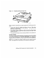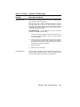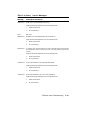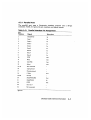
1
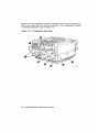
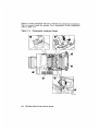
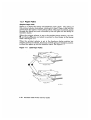
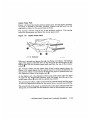
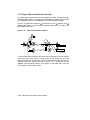
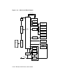
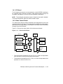
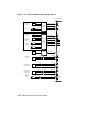
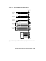
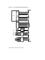
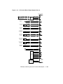
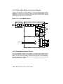
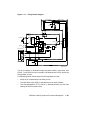
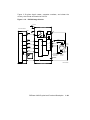
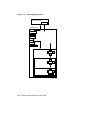
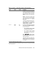
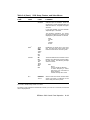
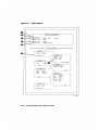
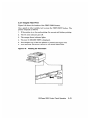
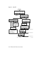
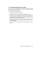
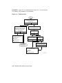
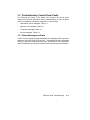
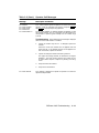
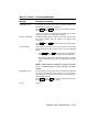
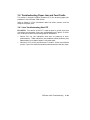
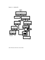
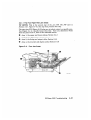
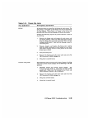
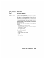
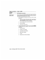
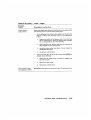
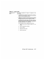
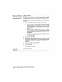
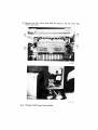
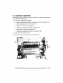
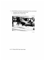
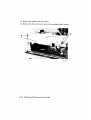
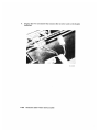
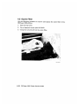
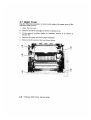
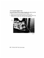
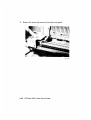
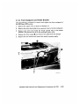
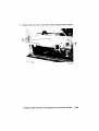
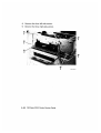
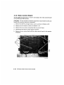
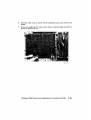
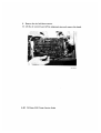
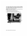
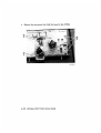
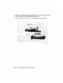
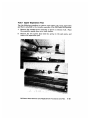
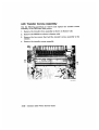
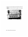
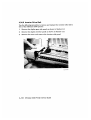
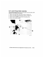
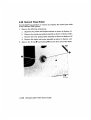
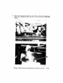
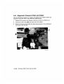
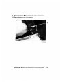
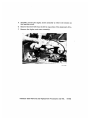
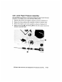
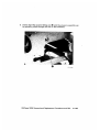
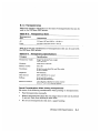
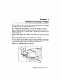
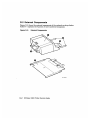
1.3.2 Paper Path Jam Detection Circuits
The paper path sensors monitor the progress of a sheet of paper through
the duplex paper path. The sensors are actuated by linkages that protrude
into the paper path and are deflected by the forward-moving paper.
!
"
#
Figure 1–9 shows the location of
the fixing unit exit,
inverter, and
second pass sensors. It also shows the duplex paper path, the rollers, and
the facedown fork gate.
Figure 1–9: Paper Path Sensor Locations
1
2
3
MLO-004931
The dc control board monitors the sensors during power-up and at specific
times during the print cycle. During power-up the fixing unit exit and
second pass sensors are checked. If either sensor detects paper, the printer
does not warm up, display READY, or go on line. The printer can be
powered up and display READY with paper in the paper path, but not
if the paper is under either sensor.
1–14 DEClaser 2200 Printer Service Guide
During the print cycle, the dc control board compares the timing and sensor
events to track the paper as it travels through the paper path. The print
cycle is initiated when a sheet of paper is fed into the paper path; the
cycle ends at the selected output stack. If the leading or trailing edge of
the paper fails to actuate a sensor within the expected time period, the dc
control board lights the control panel jam indicators, shuts down the fixing
unit heater, and causes the control panel beeper to sound.
The three jam indicators show the most probable location of a paper jam.
One sheet of paper can cause one, two, or all three indicators to light.
Figure 2–1 shows the three control panel jam indicators.
1.4 Electronic Block Diagrams
Figure 1–10 shows the major electronic components that operate the
DEClaser 2200 printer.
DEClaser 2200 Physical and Functional Description
1–15
Figure 1–10: 2200 Overall Block Diagram
Optical Fiber
Laser/Scanner
Assembly
Control
Panel
Laser
Diode
Scanner
Motor
Primary
Corona/Grid
Bias
Transfer
Corona
Video
Control
Board
DC
Control
Board
HVPSA
Developing
Bias
Static Charge
Eliminator
Toner Sensor
Solenoid and
Sensor Board
Printer Unit
Sensors/Solenoids
Duplexing Unit
Sensors/Solenoids
Host
System
I/O
Board
Fixing Unit
Duplexing
Unit Motor
Preconditioning
Exposure Lamps
Main Motor
LVPSA Main
Motor Driver
Safety
Power Switch
AC Driver
MLO-004926
AC Inlet
1–16 DEClaser 2200 Printer Service Guide
1.4.1 I/O Board
The I/O board can connect to a host system by a serial RS232C interface or
by a parallel 8-bit Centronics interface. Data passes directly through the
I/O board. See Section A.3 for pin-out and connector information.
NOTE: The switchpack mounted on some I/O boards is not used in the field.
The correct operational setting for both switches is open.
1.4.2 Video Control Board
The video control board receives commands and image data from the host
system through the I/O board. The image data is compiled into a dot pattern
and stored in the page memory to be output to the laser scanner assembly
through the dc control board.
Figure 1–11 shows the major blocks of the video control board.
Figure 1–11: Video Control Board
A23-16
EEPROM
M-CPU
AD15-0
Expansion
ROM
GA2
Font
0
Cartridges 1
S-CPU
DC Control
Board
GA1
MD
15-0
Internal
ROM
I/O
Board
Control Panel
Indicators
Display
Keys
DRAM
MD15-0
MLO-004912
•
The main central processing unit (M–CPU) is a 32-bit microprocessor
that controls all activity on the video control board.
•
The subcentral processing unit (S–CPU) is a 16-bit microprocessor that
operates as a slave to the M–CPU.
DEClaser 2200 Physical and Functional Description
1–17
The S–CPU does the following.
–
Controls the host system and video control board communication,
through the logic on the I/O board.
–
Reads and operates the keys, display, and all indicators on the
control panel except the jam indicators. (The jam indicators are
operated by the dc control board.)
–
Controls read/write access to the electrically erasable programmable
read-only memory (EEPROM). The EEPROM is referred to as
NVRAM by the control panel display (nonvolatile random-access
memory).
–
Operates the dc control board through 14 logic level signals shown
in Figure 1–12 and Figure 1–14.
–
Generates refresh clock pulses that maintain data bits stored in
dynamic random-access memory (DRAM).
–
Controls all communication between the M–CPU and elements on
the video control board.
•
Gate array 1 (GA1) controls the direct memory access (DMA) process
to the DRAM. The DRAM is accessed by the dc control board and by
devices on the video control boards.
•
Gate array 2 (GA2) controls the transfer timing of the dot pattern data
to the dc control board.
•
The DRAM is divided into the following three fields (the size of which
is adjustable through the control panel setup menu):
•
–
The page or input buffer contains data received from the host
system.
–
The page memory contains the image data bitmap or dot pattern
data.
–
The font cache memory contains processed fonts.
The read-only memory (ROM) holds the image data that makes up the
internal fonts and stores the firmware operating programs of the video
control board.
1–18 DEClaser 2200 Printer Service Guide
1.4.3 DC Control Board Signals
The dc control board operates and distributes power to all the electronic and
electromechanical components in the duplex unit and print engine. With
the exception of the scanner assembly, all connections to the dc control
board are made by the following three connectors:
•
J214 is a 40-pin connector that carries all print engine connections.
•
J215 is a 40-pin connector that carries all duplex and inverter unit
connections.
•
J216 is a 9-pin, high current type connector that connects dc power to
the dc control board.
Figure 1–12 and Figure 1–13 show the input signals to the dc control board
from the print engine, duplex unit, and video control board.
DEClaser 2200 Physical and Functional Description
1–19
Figure 1–12: DC Control Board Input Signals (Part 1)
DC Control Board
+5V
Paper Exit
Sensor
J331-7 J214-13
PS331
TH1
Thermistor
Fixing
Unit
-6
-15
-5
-17
-4
-19
PDP
TB301-1
-2
FSRTH
+5V
Upper Paper
Sensor
PS301
Upper
Manual Feed
Sensor
PS302
J213-7 J214-24
-6
Solenoid
and
Sensor
Board
SW301
Sensitivity
Switches
SW302
Toner
Sensor
-26
-8
-22
-9
-20
-1
-36
-2
-34
J601-5 J214-10
HVPSA
PEMPU
MPFUS
CSENS1
CSENS2
TSENS
+24V
Inverter Paper
Sensor
PS4
J715-3
-2
J714-5
-4
J215-20
-22
-1
-3
-24
PRS
+24V
Duplexing Unit
Motor Clock
PS2
J712-3
-2
J215-8
-10
-1
-12
DMTG
+24V
Paper Alignment
Guide Home
Position Sensor
Printout
Selector
Switch
PS5
MS1
J718-3
-2
J717-5
-4
J215-30
-28
-1
-3
-26
J714-2
J215-32
-1
-34
HMPS
FUPSENS
MLO-004927
1–20 DEClaser 2200 Printer Service Guide
Figure 1–13: DC Control Board Input Signals (Part 2)
DC Control Board
+24V
Lower
Manual Feed
Sensor
PS6
J719-3
-2
J215-6
-1
-1
-2
J711-3
-2
J215-6
-4
-1
-2
J713-3
-2
J215-18
-16
-1
-14
MPFLS
+24V
Lower Cassette
Paper Sensor
PS1
PEMPD
+24V
Second-Pass
Pickup Unit
Paper Sensor
PS3
SW263
Upper Cassette
Size-Sensing
Switch
SW262
SW261
DUPFEDS
J216-1
J214-35
PSIZEU1
-2
-37
PSIZEU2
-3
-4
-39
-40
PSIZEU3
SW201
PSIZED1
Lower Cassette
Size-Sensing
Switch
SW202
PSIZED2
SW203
PSIZED3
PRNT
Video
Control
Board
VXYNC
CPRCY
VDO
CMD
CCLK
MLO-004928
Figure 1–14 and Figure 1–15 show all the output signals from the dc control
board.
DEClaser 2200 Physical and Functional Description
1–21
Figure 1–14: DC Control Board Output Signals (Part 1)
DC Control Board
+5V
J451-1
J202-4
-2
-3
-3
-2
-4
-1
Laser
Diode
Driver
LDRV
PD
DSADJ
+24V
Scanner
Assembly
J401-1
J203-7
-3
-5
-4
-3
-5
-1
-2
-6
J601-8
J214-4
Scanner
Motor
SCNCONT
TG(+)
TG(-)
+24V
HVPSA
-6
-8
-4
-12
-3
-14
-2
-16
-1
-18
-7
-6
DBDC
DBAC
HV1ON
HVRST
HVTON
LVPSA
Main
Motor
Main
Motor
Driver
M1
+24V
Upper
Pickup
Clutch
Solenoid
Registration
Clutch
Solenoid
SL301
J213-5
J214-28
-4
-30
-3
-32
-6
-26
J151-10
J214-33
-7
-27
-8
-29
-9
-31
Solenoid
and
Sensor
Board
SL302
CPUDU
REGD
+24V
FM1
J152-1
-2
AC Inlet
Assembly
Fixing
Unit
∼
FAN
FRSD
AC Power
MLO-004929
1–22 DEClaser 2200 Printer Service Guide
Figure 1–15: DC Control Board Output Signals (Part 2)
DC Control Board
+24V
Preconditioning
Exposure Lamps
TB321
J333
TB322
J334
Duplex Unit
Motor
M2
Inverter Roller
Solenoid
SL6
J333-1
Fixing
Unit
J214-25
-3
-21
-2
-23
J702-1
-2
J706-4
-3
PEXP
J215-7
DMDVO
-9
DMDVO
+24V
-29
-27
SBSLD
+24V
Fork Gate
Solemoid
SL7
J707-2
-1
-33
-31
EXDEF
+24V
Alignment
Roller Pressure
Solenoid
SL3
J704-2
-1
-17
-15
SFTSLD
+24V
Alignment
Guide Clutch
Solenoid
SL4
J705-2
-1
SL2
J703-2
-1
J717-2
-1
-21
-19
GUIDSLD
+24V
Second-Pass
Pickup Clutch
Solenoid
-13
-11
DUPFED
+24V
Lower Cassette
Pickup Clutch
Solenoid
SL1
J701-1
-2
-3
-5
CPUDD
+24V
Inverter Roller
Clutch
Solenoid
SL5
J706-2
-1
-25
-23
SBROLD
+24V
J207-1
FM2
-2
BD
PPRDY
Video
Control
Board
RDY
VSREQ
SBSY
STS
PCLK
Control Panel
Jam and Feed
Source
Indicators
SW205
MLO-004930
DEClaser 2200 Physical and Functional Description
1–23
1.4.4 LVPSA, Main Motor, and Interlock Diagram
Figure 1–16 shows the major sections of the low-voltage power supply
assembly (LVPSA). The LVPSA consists of dc low-voltage power supply
regulators, two interlock switches, and the high current drivers for the
main motor that drives the print engine.
Figure 1–16: LVPSA Block Diagram
Power
Switch
Circuit
Breaker
Noise
Filter
LVPSA
DOROPN
SW2
Fuse
Noise
Filter
CB
101
Rectifier
Oscillator
T1
Rectifier
+ 5V Power
Supply
+ 5V
F1
AC Inlet
Reset Signal
Generator
RESET
REMOTE
Rectifier
+ 24V
Power
Supply
+ 24VA
+ 24VB
SW1
Rectifier
- 5V Power
Supply
-5V
Motor Driver
J3
DC Control
Board
M1
MLO-004916
1.4.5 Fixing Heater Control Circuit
The fixing heater current is controlled by ac driver and safety circuits,
whereas the fixing temperature is measured and regulated by the dc control
board. The ac driver and safety circuit are parts of the ac inlet assembly
field replaceable unit (FRU). Figure 1–17 is a diagram of the circuits that
control the fixing unit heater.
1–24 DEClaser 2200 Printer Service Guide
Figure 1–17: Fixing Heater Diagram
Current Sensor
Safety Circuit
Q153
C153
Power
Switch
AC Driver
CB
101
AC Power
Noise
Filter
RL101
H1
LVPSA
TP1
SSR
101
DC Controller
FSRD
FSRTH
TH1
SW205
MLO-004917
The ac line power is directed through the power switch, noise filter, and
CB101. From CB101 the ac line power is directed to the LVPSA and to the
fixing heater circuits.
The following serial devices control the fixing heater current:
•
Relay RL01 is operated by the safety circuit.
•
The solid state relay (SSR) is operated by the dc control board.
•
The thermoprotection (TP1) switch is actuated directly by the heat
coming off the fixing heat roller.
DEClaser 2200 Physical and Functional Description
1–25
Safety Circuit
The safety circuit consists of a fixing heater current monitor and a timer
circuit that controls relay RL01. The current transformer monitors the
current drawn by the fixing heater and charges C153. If the fixing current
get too high, C153 turns on Q153, which opens the RL01 contact. The
signal also causes C153 to fully charge when a fixing unit error (50
SERVICE) has occurred.
FSRD
Once RL01 has opened, it is kept open until C153 discharges. C153 stays
fully charged until the ac power is turned off, then C153 slowly discharges.
About 10 minutes are required for the discharge. If you turn the power back
on before C153 discharges, C153 recharges and the 50 SERVICE message
is redisplayed.
SSR Circuit
The SSR switches the fixing heater current on and off to regulate the fixing
unit temperature. The resistance of the thermistor (TH1) varies according
to the heat of the fixing roller. The dc control board measures the resistance
of TH1 and turns SSR on to raise the temperature or off to allow the fixing
unit to cool.
•
When the printer is at standby, the fixing temperature is maintained
at 165°C (329°F).
•
When the printer starts to print, the fixing temperature is quickly
raised to 180°C (356°F).
The dc control board displays the 50 SERVICE error message if the fixing
unit roller temperature:
•
Fails to exceed 30°C (86°F) within 18 seconds after power on
•
Fails to exceed 165°C (329°F) within 90 seconds after power on
•
Exceeds 230°C (446°F)
•
Drops below 140°C (284°F) after the Ready indicator goes on
1–26 DEClaser 2200 Printer Service Guide
SW205
Switch SW205 is mechanically actuated by the bottom cover. When the
bottom cover is on, the switch is open and TH1 operates normally. When
the cover is off, the SW205 is closed and a dummy load is connected
across TH1, thus simulating a correctly warmed fixing temperature. The
dc control board never turns on the SSR, and the fixing unit stays cool.
SW205 is not used in the field. The TP1 thermoprotection switch is a
passive temperature-operated switch that is mounted next to the fixing
heater roller. TP1 opens if the fixing unit temperature climbs to 210°C
±10% (410°F).
1.4.6 HVPSA Circuits
The HVPSA assembly consists of the high-voltage power supplies and an
attached connector block that are crucial to the production of the image.
The assembly is replaced as an FRU. You should not attempt to adjust the
HVPSA in the field.
When the top cover is closed, the EP-S cartridge contacts make connection
with the coil and flat spring contacts of the connector block. The coil
spring contacts are used for high-voltage connection. The flat spring
contacts connect the toner sensor signal and high-voltage common return
bus (HVGND) to the EP-S cartridge.
The coil spring connectors are chrome plated and require no maintenance.
Use a soft brush to clean away dust or paper chips, but avoid using
commercially available liquid or aerosol contact cleaners. Replace the
HVPSA if the connector block plastic is broken or damaged, or if the
contacts appear burnt, pitted, or bent. Do not attempt to scrape clean,
bend back, or repair damaged contacts.
DEClaser 2200 Physical and Functional Description
1–27
Figure 1–18 presents a side profile of the connector block and identifies
each connector.
Figure 1–18: HVPSA Connector Block
Primary
Corona
Primary
Corona Grid
Developing Bias
HVGND
Static Charge
Eliminator
Toner Sensor
Transfer
Corona Unit
1–28 DEClaser 2200 Printer Service Guide
MLO-004924
Figure 1–19 gives signal names, connector numbers, and shows the
circuitry that drives and loads the HVPSA.
Figure 1–19: HVPSA Image Circuits
+24 Vdc
8
DC Control Board
HVPSA
J214
7
M-CPU
T1
DB
DBDC
8
6
A
Grid
DBAC
12
Primary Corona
4
HVION
14
P
T3
3
T
Drum
HVTON
18
Toner
Sensor
D
1
HVRST
16
2
Separation
Static Charge
Eliminator
LVPSA
RESET
Developer
Drum
Transfer
Corona
HVGND
TSENS
10
5
MLO-004925
DEClaser 2200 Physical and Functional Description
1–29
Table 2–2 (Cont.): Control Panel Keys
&
'
(
Menu
< 1
Causes the printer to enter the setup menu and redefines the function
of the dual-labeled keys. Section 2.2 gives more information about the
setup menus.
Duplex
Toggles the paper path between single or two-sided printing, but only if
the printout selector is set to the facedown print position.
You must manually set the printer to simplex or duplex mode; there is
no software command to do this.
Feeder Select
Toggles the feed source indicators and the following display messages:
•
FEEDER = Auto
•
FEEDER = Lower
•
FEEDER = Upper
•
FEEDER = Manual (The indicator and display text appear only if
the printer is in simplex test mode.)
•
FEEDER = Option (The indicator and display text appear only if
the optional envelope feeder is installed and if faceup stacking and
simplex printing are selected.)
2.2 Menu Operation
As shown in Figure 2–3, when you press Menu you enter the first of a threelevel setup menu. Table 2–4 lists all of the setup menus, features, and
values.
DEClaser 2200 Control Panel Operation
2–5
Figure 2–3: 2200 Keypad Operation
Online Operation
ON LINE
Offline READY
On Line
Form Feed
Error Skip
Test/Font
Reset
Menu
Duplex
Manual Feed
Setup mode menu
Scroll
Feature menu
Scroll
Value menu
Scroll
ENTER
MLO-004918
2–6 DEClaser 2200 Printer Service Guide
2.2.1 Setup Menu Format
The horizontal format of the text in the setup menu display is unique.
Figure 2–4 shows how the text appears in the window when the printer is
in a setup, feature, or value menu. You press the function keys to move
through the selection. The selected text is left-justified and indicated by an
underline cursor. Ignore any text, separated by a space, on the right of the
display.
Figure 2–4: Setup Menu Display Text
.. LOAD< -ROM
.
FONT/FEED
LAYOUT
COPY/OVERLAY
16 Characters
Press
to scroll to the left
LOAD< -ROM
FONT/FEED
Press
LAYOUT
to scroll to the right
COPY/OVERLAY
MLO-004919
2.2.2 Moving, Selecting, and Saving Values
Table 2–3 shows the action of the function keys when you scroll through
the setup, feature, and value menus.
Table 2–3: Menu Scrolling Keys
Key
_
^
Function
Shifts down through the feature and value menus. Down-shifting stops
after the value menu.
Shifts up through the value, feature, and setup menus. Up-shifting stops
at the offline ready level.
DEClaser 2200 Control Panel Operation
2–7
Table 2–3 (Cont.): Menu Scrolling Keys
Key
>
and
Function
<
Use for scrolling through the selection of the setup, feature, and value
menus.
The circular scrolling action returns to the starting selection after stepping
through each available selection. When a scrolling key is pressed, the text
and cursor move. The selected text is left-justified and is indicated by an
underline cursor.
Enter
Enters the selected value into the operational memory space and marks
the value with an equal (=) sign .
Table 2–4 describes the setup, feature and value menus.
Table 2–4: 2200 Setup, Feature, and Value Menus
Setup
Level
Feature
Level
Value
Level
FONT/FEED
feeder
=Auto
Lower
Upper
Manual
Option
Comment
The action of this parameter is exactly the
same as pressing Feeder Select .
When you select Auto, the printer
automatically selects the upper or lower
cassette. Both cassettes must be the same
size or a U<–>L error occurs. The feed
indicator shows which cassette is selected.
See Table 3–2 for additional information.
The Lower or Upper value selects the
lower or upper cassette and turns on the
corresponding indicator.
The LOAD<– ROM factory values are in bold.
The equal (=) sign indicates the selected value. When you scroll into a value level, the selected
value is displayed first.
2–8 DEClaser 2200 Printer Service Guide
Table 2–4 (Cont.): 2200 Setup, Feature, and Value Menus
Setup
Level
Feature
Level
Value
Level
Comment
When you select Manual, the display
prompts you to load a sheet of paper into
the manual feeder. When the manual feed
sensor detects the paper, the dc control
board activates the paper feed clutch
and feeds the paper into the registration
rollers.
NOTE: The Manual display text
and control panel indicator appear
only if the printer is in simplex
test mode.
The Option display text and indicator appear only if the optional
envelope feeder is installed and
faceup stacking is selected.
LAYOUT
offsetX
offsetY
n.n
=0.0
The X and Y offset features use the same
value format. The selected value causes a
shift of the printed image on the page, in
the selected dimension:
•
The X dimension shifts the image
from side to side by varying the start
of the beam on the OPC drum.
•
The Y dimension shifts the image
from leading to trailing edge by
varying the timing of the registration
clutch solenoid.
Pressing < or > increments or decrements the displayed value by ±0.5. Each
0.5 change shifts the image by ±15 dots or
±0.05 in. (±1.27 mm).
The minimum value is 0.0, which corresponds to the center of the sheet. The
maximum value is ±10, which would shift
the image about 1.0 inch in the selected X
or Y direction.
The LOAD<– ROM factory values are in bold.
The equal (=) sign indicates the selected value. When you scroll into a value level, the selected
value is displayed first.
DEClaser 2200 Control Panel Operation
2–9
Table 2–4 (Cont.): 2200 Setup, Feature, and Value Menus
Setup
Level
Feature
Level
Value
Level
LAYOUT (Cont.)
autoNL
ON
=OFF
Determines if the line of text is truncated
or wrapped at the right-hand margin.
When set to ON, the printer automatically
inserts a carriage return and line feed
character to wrap the text on the next line.
When set to OFF, the printer truncates the
line at the right-hand margin.
COPY/OVERLAY copy
nn
=00
Determines the number of copies of a page
that the printer prints. For example, if set
to =05, five copies of each page are printed
before the printer accepts the next page
from the host system. The number counts
from 01–99 in increments of 1.0.
COMMAND
message
English
=Finnish
French
German
Italian
Japan
Norway
Port.
Spanish
Swedish
Danish
Dutch
The language text appears on the display
when the printer is in the online ready
mode. The setup menus always are displayed in English.
INITIAL
macro
yyy
000
Counts up or down from 000–099 in
increments of 1.0.
Comment
The macro feature is used to set the
printer environment to match that of the
host system. The macro number is a
combination of the device identification
and character set (Cset) numbers. The
sum of the two numbers is entered as the
macro number. See Appendix A for a list
of identification and Cset numbers.
The LOAD<– ROM factory values are in bold.
The equal (=) sign indicates the selected value. When you scroll into a value level, the selected
value is displayed first.
2–10 DEClaser 2200 Printer Service Guide
Table 2–4 (Cont.): 2200 Setup, Feature, and Value Menus
Setup
Level
Feature
Level
Value
Level
INITIAL (Cont.)
paint
Partial
=Full
Dual
Comment
The amount of available memory determines which values are displayed.
•
If the minimum amount of memory
is installed (1024 KB), you can only
select the Partial value; Full and
Dual are not displayed.
•
If the 1-MB optional memory is
installed, you can select Partial or
Full; Dual is not displayed.
•
If either the 2-MB or 3-MB optional
memory or more is installed, you can
select Partial, Full, or Dual.
The paint selection allocates the size of
the font cache and page areas of available
memory. As more and more processed
(bitmapped) fonts are cached, more of the
available memory is utilized; this leaves
less room for bitmapped print data and
slows down the printer. More time is
required to bitmap a smaller area, which
eventually causes the 21 COMPLEX
DATA message to be displayed.
See
Table 3–3 for additional information.
•
When you select Partial, a portion of
a page is bitmapped, then printed.
•
When you select Full, one full page is
bitmapped, then printed.
•
When you select Dual, two complete
single-page bitmaps are reserved in
memory. This enables the printer to
simultaneously print page one and
bitmap page two.
The LOAD<– ROM factory values are in bold.
The equal (=) sign indicates the selected value. When you scroll into a value level, the selected
value is displayed first.
DEClaser 2200 Control Panel Operation
2–11
Table 2–4 (Cont.): 2200 Setup, Feature, and Value Menus
Setup
Level
Feature
Level
Value
Level
INITIAL (Cont.)
paper
Letter
A4
Comment
The selected value of the paper feature
establishes the default size of the image
and the sheet of paper that are requested
for manual feeding.
The printer adjusts the size of the image
to fit on the requested size sheet and
displays the paper feed message to prompt
an operator to load a specific size sheet of
paper. See the PF FEED messages listed
in Table 3–2 for details of the paper feed
message.
The following actions establish the size of
the printed image and the requested sheet
size:
1.
Escape sequences transmitted from
the attached host system select any
of the standard sizes or can set a
variable size.
2.
If no escape sequences are received
(for example, when you print the test
patterns in offline ready mode), the
cassette size key selects the image
and paper size to the size of the
installed and selected cassette.
3.
If no escape sequences are received
and no cassette is installed, the
selected paper value determines the
image size and the paper feed size.
The LOAD<– ROM factory values are in bold.
The equal (=) sign indicates the selected value. When you scroll into a value level, the selected
value is displayed first.
2–12 DEClaser 2200 Printer Service Guide
Table 2–4 (Cont.): 2200 Setup, Feature, and Value Menus
Setup
Level
Feature
Level
Value
Level
INTERFACE
i/f
=RS232C
CENTRO
Comment
If you select CENTRO, the parallel 8-bit
Centronics port is activated. There are
no features or values associated with the
CENTRO selection. All speeds and signals
are fixed.
If you select RS232C, the serial RS232C
compatible port is activated.
The following parameters are always
printed on the Test Print A sheet, but are
displayed only when RS232C is selected.
baud
rsmode
dtr
xon/xoff
etx/ack
baud1
19200
9600
4800
=2400
1200
600
300
Establishes the baud rate of the serial
port. The baud rate of the printer must
match the baud rate of the host system.
rsmode1
8S
8SS
=7OS
7ES
7OSS
7ESS
8OS
8ES
The values define the characteristics of the
RS232C serial data byte and must match
the host system. The following example
shows the format:
READY-H
=Fix–H
Sets the state of the serial connector DTR
signal to be fixed or conditional to the
online ready state of the printer.
dtr1
8OS
where:
8 is the number of data bits.
O means odd parity, E means
even parity, no O or E means no
parity checking.
S means one stop bit is used.
1 This
value appears only if you select RS232C.
The LOAD<– ROM factory values are in bold.
The equal (=) sign indicates the selected value. When you scroll into a value level, the selected
value is displayed first.
DEClaser 2200 Control Panel Operation
2–13
Table 2–4 (Cont.): 2200 Setup, Feature, and Value Menus
Setup
Level
Feature
Level
Value
Level
Comment
xon/xoff1
=ON
OFF
If you select ON, XON/XOFF flow control
is enabled.
INTERFACE
etx/ack1
=ON
OFF
If you select ON, ETX/ACK flow control is
enabled.
SAVE–>RAM
ok
–
Writes the selected value of COPY/
OVERLAY and autoNL into RAM.
SAVE–>NVRAM
ok
–
Writes all the selected values into NVRAM.
The contents of NVRAM are retained
through a power-down cycle.
LOAD<–ROM
ok
–
Loads all factory values from ROM to
selected values.
1 This
value appears only if you select RS232C.
The LOAD<– ROM factory values are in bold.
The equal (=) sign indicates the selected value. When you scroll into a value level, the selected
value is displayed first.
2–14 DEClaser 2200 Printer Service Guide
Figure 3–1: Start FIP
Start
Turn on the printer power. Do you hear
the motors turn or see any activity on
the control panel indicators or display?
No
Yes
Go to Section 3.2
or Figure 3-2
Is the control panel blank, hung,
or not functioning correctly?
Hung
Is 00 READY displayed or is
the Alarm indicator on with an
error message displayed?
Press the Test Print button. Does
the engine test pattern print?
Yes
Functioning
No
00 READY
Check the LVPSA
voltages or swap
the LVPSA. Does
the problem still
exist?
Alarm
Print and examine
Test Print B.
Is 00 READY displayed or is
the Alarm indicator on with an
error message displayed?
Check the display
panel connectors.
No
Yes
Go to Section 3.3
Swap the following components
to fix the problem:
Did any paper
jams occur?
Display panel
Video control board
DC control Board
No
Yes
Go to Section 3.4
Are there any image
defects?
No
Yes
Go to Section 3.5
Go to TCC Appendix
MLO-004920
3–2 DEClaser 2200 Printer Service Guide
3.2 Troubleshooting Power-Up Faults
You see and hear the following when you power up the DEClaser 2200
printer, assuming that both cassettes and an EP-S cartridge are installed
and no error condition is detected.
1. All control panel indicators come on.
2. Solid blocks are momentarily displayed.
If optional memory is installed, an active display pattern occurs.
3. The scanner, main, and duplex motors start up with a whirring sound.
If any paper is left in the fixing unit, it moves into the fixing unit
exit, inverter, or second pass sensor to produce a 13 PAPER JAM error
message, and the fixing heater does not start.
4. The text 02 WARMING UP is displayed and the Ready indicator flashes.
It takes less than two minutes to achieve the 160°C (320°F) fixing unit
standby temperature.
5. The text 00 READY is displayed and the Ready indicator comes on
steadily.
DEClaser 2200 Troubleshooting
3–3
FIP NOTES: Figure 3–2 is a continuation of Figure 3–1. Turn to the start
FIP (Section 3.1) for general FIP information.
Figure 3–2: Power-Up Fault
Start
No printer response to power-up.
Is the ac power O.K. at
the wall plug?
Bad AC
Call site electrician to connect
or restore the ac power to the
wall outlet. Does the printer
blow the site power line
circuit breaker?
Yes
No
O.K.
Check/replace the power cord.
Does the problem still exist?
Is CB101 open
(is the button up)?
Yes
The problem is in one of
the following components:
Inspect the ac
line cord.
No
Reset CB101. Does
CB101 open again?
Is the LVPSA
fuse blown?
Yes
Replace the ac
inlet assembly.
No
Yes
Replace the fuse.
Does the fuse blow again?
Return to start on
FIP Figure 3-1.
Yes
Swap the following components
to fix the problem:
Fixing unit
LVPSA
AC inlet assembly
MLO-004921
3–4 DEClaser 2200 Printer Service Guide
3.3 Troubleshooting Control Panel Faults
The following list points to the tables that interpret the control panel
display text and give information about troubleshooting. A fault condition
exists if messages are displayed frequently or continuously.
•
Operational status messages, Table 3–1
•
Operator call messages, Table 3–2
•
Functional messages, Table 3–3
•
Service messages, Table 3–4
3.3.1 Status Message and Faults
Table 3–1 lists the display panel messages that are displayed during normal
operation of the DEClaser 2200 printer. The operational status messages
directly indicate the condition of the printer. See Section 2.1 for information
about the operation and functioning of the control panel keys and indicators.
DEClaser 2200 Troubleshooting
3–5
Table 3–1: Operational Status Messages
Number
Message
Description and Action
00 READY
The printer is ready to print. If the On Line indicator is on, print
files can be sent from the host. If the On Line indicator is off, the
printer is in the offline ready mode. In the normal mode you can
print test sheets, enter the setup menus, or perform any offline
task.
01 Test Print B
The printer is generating and printing Test Print B. See
Section 2.3.3 for more information about Test Print B.
02 WARMING UP
The printer is waiting for the fixing unit to reach operating
temperature. If the fixing unit fails to reach the correct operating
temperature, the 50 SERVICE message is displayed.
03 RESET
This message is displayed for about four seconds to confirm that
the reset function is completed. Pressing Reset initiates the reset
function.
04 TEST STOP
This message is displayed to show that the generation and printing
of a test pattern is stopping. The message is displayed while the
remaining paper is printed and ejected.
05 TEST PRINT A
This message is displayed during the generation and printing of
Test Print A.
06 FONT LIST
This message is displayed during the generation and printing of
the Font List.
06–10
Not used.
3–6 DEClaser 2200 Printer Service Guide
3.3.2 Operator Call Messages and Faults
When an operator call condition occurs, the printer goes off line and an
operator call message is displayed. The message disappears automatically
as soon as the condition is corrected. A fault condition exists when the
message cannot be cleared or is displayed for no apparent reason.
Table 3–2 lists all operator call messages, explains the message, and
provides troubleshooting information if the message faults.
Table 3–2: Operator Call Messages
Number
Message
11 PAPER OUT
Description and Action
The selected cassette or envelope feeder is empty or no cassette is
installed in the selected cassette slot. An unselected cassette slot
is ignored.
The paper-out sensor and linkage detect an empty cassette and the
cassette size-sensing switches detect a missing cassette.
Troubleshooting
Use the following procedure to fix a paper
out fault:
1.
Select or install a full cassette.
2.
Inspect and swap the cassette.
3.
Inspect and swap the paper-out sensor assembly.
The upper cassette paper-out sensor is located on the solenoid
and sensor board that is part of the LVPSA. The lower cassette
paper-out sensor is attached to the duplex bulkhead. Inspect
the linkage for freedom of movement and damage.
4.
Inspect and swap the cassette size-sensing switches.
The upper size-sensing switches are attached to the engine
baseplate. The lower size-sensing switches are on the dc
control board. Repair or replace any binding or sticking
levers.
5.
Swap the dc control board.
6.
Swap the video control board.
DEClaser 2200 Troubleshooting
3–7
Table 3–2 (Cont.): Operator Call Messages
Number
Message
12 PRINTER OPEN
Description and Action
This message is displayed when the top cover of the printer is open.
When the top cover is closed, the top cover switch lever presses the
interlock switches. One interlock switch interrupts the main motor
drive current, the other switch signals the dc control board.
Troubleshooting Do the following if closing the cover does
not automatically clear the error:
13 PAPER JAM
1.
Inspect the top cover switch lever for any damage. Make sure
you hear both switches actuate as the top cover is closed. Do
not confuse the sound of the drum sensitivity switches with
that of the interlock switches.
2.
Inspect and manually actuate the interlock switch. Fix or
replace the LVPSA if you find the switches are damaged or
not operable.
3.
Replace the LVPSA.
4.
Replace the dc control board.
This message is displayed when paper is jammed in the paper
path. The dc control board inhibits printer operation until you
clear out the paper and return the printer to online operation.
The indicators on the jam panel show the most likely position of
the jam.
The jam display and indicators clear when you open and then close
the top cover or when you press Error Skip .
Troubleshooting To begin troubleshooting a jam, turn to the
start FIP at Figure 3–3.
3–8 DEClaser 2200 Printer Service Guide
Table 3–2 (Cont.): Operator Call Messages
Number
Message
14 NO EP-CART
Description and Action
This message is displayed when the top cover is closed and both
drum sensitivity switches remain off.
When the top cover is closed, the sensitivity tabs on the EP-S
cartridge actuate one or both of the drum sensitivity switches
that signal the dc control board. The dc control board responds
to the signal by setting the laser beam intensity and allowing the
initialization process to proceed.
Troubleshooting
Do the following if the error cannot be
cleared or if it appears intermittently:
15 ENGINE TEST
1.
Inspect the sensitivity tabs on the EP-S cartridge. Either one
or two tabs must be installed. If there are no tabs, replace
the EP-S cartridge.
2.
Inspect the levers that actuate the drum sensitivity switches
on the solenoid and sensor board. Make sure the switches
actuate when the top cover is closed. Replace the LVPSA if
the sensitivity switches are defective.
3.
Swap the LVPSA.
4.
Replace the dc control board.
This message is displayed during the generation and printing of
the print engine internal test pattern, which is initiated when you
press the TEST PRINT button on the dc control board.
DEClaser 2200 Troubleshooting
3–9
Table 3–2 (Cont.): Operator Call Messages
Number
Message
16 TONER LOW
Description and Action
This message is displayed if the toner supply in the EP-S cartridge
is exhausted or if the toner is compacted into cakes and unable to
flow.
Troubleshooting Do the following if the message is
intermittent or cannot be cleared:
1.
Remove and agitate the EP-S cartridge to loosen up the toner.
Replace the EP-S cartridge if the printer prints for a while,
then the message is redisplayed.
2.
Inspect the HVPSA and EP-S connectors for dirt, pitting,
damage, or contamination. If any damage is found, replace
the FRU. Do not try to scrape, bend, or repair the contacts.
Remove any dust or paper chips with a dry brush. Do not
use liquid, aerosol, or any other type of contact cleaner on the
high-voltage connectors.
17 U<–>L
3.
Swap the EP-S cartridge.
4.
Swap the HVPSA.
5.
Replace the dc control board.
This message is displayed when the feeder selection is set to
automatic and two different size cassettes are installed or if one of
the cassettes is out of paper.
To clear the display, make sure both cassettes are fully installed,
are the same size, and contain paper.
Troubleshooting
This fault condition is usually caused by a
bad component in either the upper or lower feed slot. When the
error occurs, the control panel feed source indicators might point
to the malfunctioning feed slot.
1.
Select and test each upper and lower cassette individually.
Press Feeder Select to select FEEDER = UPPER, then press
again to select FEEDER = LOWER.
2.
If the 17 U<–>L message is still displayed when FEEDER =
AUTO is selected, swap the dc control board.
3–10 DEClaser 2200 Printer Service Guide
Table 3–2 (Cont.): Operator Call Messages
Number
Message
18 EC INCORRECT
Description and Action
This message is displayed whenever the envelope cassette is
installed in the lower cassette slot. Do not confuse the envelope
cassette with the optional envelope feeder.
To clear the display, remove the envelope cassette and install it in
the upper cassette slot.
Troubleshooting
A fault exists if this message is displayed
and the envelope cassette is not installed in the lower slot. Do the
following to fix the problem:
19 PAPER PATH 3
1.
Inspect the actuation levers of the lower cassette size-sensing
switches. Fix or replace any damaged or nonfunctioning
components.
2.
Replace the dc control board.
This text is displayed when the host system specifies feeding from
the envelope cassette while the printout selector is set for facedown
(upper) stacking. All envelope printing requires simplex print
mode and faceup (rear) stacking.
To clear this error, turn the printout selector to the faceup stacking
position.
Troubleshooting
A malfunctioning printout selector switch
circuit causes this type of error. Refer to the troubleshooting
section of 19 PAPER PATH 4 in this table for testing and fixing
information.
DEClaser 2200 Troubleshooting
3–11
Table 3–2 (Cont.): Operator Call Messages
Number
Message
19 PAPER PATH 4
Description and Action
This message is displayed if the printout selector is turned to the
faceup stacking position while duplex printing is selected. The
printout selector switch detects the position of the printout selector
shaft.
To clear this error, turn the printout selector to the duplex
facedown stacking position.
Troubleshooting
A malfunctioning printout selector switch
circuit causes this type of error. Use the following procedure to
test and repair:
1.
Open the top cover so you can see behind the inverter unit
and make sure the inverter connectors are fully plugged into
the bulkhead of the duplex unit.
2.
Remove the inverter side panels and examine the action of the
printout selector switch. Fix or replace any damaged parts or
replace the inverter unit.
3.
Swap the dc control board.
3–12 DEClaser 2200 Printer Service Guide
Table 3–2 (Cont.): Operator Call Messages
Number
Message
PC
PC
PC
PC
PC
LOAD
LOAD
LOAD
LOAD
LOAD
Description and Action
A4
LETTER
LEGAL
EXEC.
PAPER nn
A PC LOAD request signals the operator to remove the selected
cassette, install the requested size cassette, and press Error Skip ,
then On Line to resume the printing operation.
The PC LOAD PAPER nn message requests the operator to load
the envelope cassette. The nn is the paper size code number that
corresponds to a specific type of envelope. The nn number range
is 80–99.
Troubleshooting
Do the following if the message is displayed
when the correct size cassette is installed:
1.
Inspect the cassette key and if it is damaged, replace the
cassette.
Switch the correct size cassette into the opposite slot and
select that slot. If the problem switches to the opposite slot
with the cassette, replace the cassette.
2.
Inspect and swap the cassette size-sensing switches.
The upper size-sensing switches are attached to the engine
baseplate. The lower sensing switches are located on the
dc control board. Repair or replace any binding or sticking
levers.
PC LOAD OPTION
3.
Swap the video control board.
4.
Swap the dc control board.
This message is displayed to request the operator to install the
optional envelope feeder.
DEClaser 2200 Troubleshooting
3–13
Table 3–2 (Cont.): Operator Call Messages
Number
Message
PF
PF
PF
PF
PF
FEED
FEED
FEED
FEED
FEED
A4
LETTER
LEGAL
EXEC.
PAPER nn
Description and Action
The PF FEED message requests the operator to insert a sheet of
paper into either manual paper feeder.
When the upper or lower manual feed sensor is actuated, the
printer delays momentarily to allow the operator to fully insert
the sheet, and then it feeds and prints the sheet.
The PF FEED PAPER nn message requests the operator to
manually load and feed a nonstandard size paper. The nn number
range is 80–99.
Troubleshooting Repeat the following procedure on the
upper and lower cassette slots to test, find, and fix a manual feed
fault.
1.
Press Feeder Select until the FEEDER = MANUAL message is
displayed.
2.
Press Test/Font to print a test pattern. The PF LOAD message
is displayed. The requested size paper to load is determined
by the size of the installed cassette or by the value selected
for the paper feature on the initial setup menu. See Table 2–4
for more information about the setup menu.
3.
Insert a sheet of paper into the manual feeder. A fault exists
if the message does not change and the pickup roller does not
turn.
4.
Do the following to fix a PF FEED fault:
•
Swap the LVPSA, if the upper cassette slot is faulty.
•
Swap the sensor on the lower cassette sensor assembly,
if the lower cassette slot is faulty.
•
Swap the dc control board.
NOTE: If the top sheet of the cassette paper
feeds, instead of the manual feed sheet, you
are not pushing the paper far enough or fast
enough into the manual feeder. If the sheet
feeds, but jams, go to Section 3.4.1 to fix the
paper feeding or jamming problem.
3–14 DEClaser 2200 Printer Service Guide
Table 3–2 (Cont.): Operator Call Messages
Number
Message
Description and Action
OC text
(16 characters)
Operator action request message. Press
continue printing.
Error Skip
, then
DEClaser 2200 Troubleshooting
On Line
to
3–15
3.3.3 Functional Messages and Faults
Table 3–3 lists all status messages, explains the message, and provides
troubleshooting information if the message faults.
Table 3–3: Functional Messages
Number
Message
FE FONT REMOVAL
Description and Action
A font cartridge was removed or inserted while the printer was
powered on. To clear this error, power the printer off, then on.
Always insert or remove a font cartridge while the printer is
powered off.
Swap the video control board if you cannot clear the error.
FF FONT FULL
There is insufficient memory space for loading of an additional
font or there are too many downline loaded fonts. Memory can be
cleared by a software command from the host or by pressing
Reset .
20 PAGE FULL
The host system is overflowing the page buffer memory.
Press
page.
Error Skip
, then
On Line
to print the overflow data on the next
To avoid this error, delete unused character sets and use the full
paint mode. If this error occurs frequently, the customer can install
optional memory to increase available RAM.
21 COMPLEX DATA
The host system is loading the page buffer faster then the printer
can print. Press Error Skip , then On Line to continue printing on the
next page.
Set the paint = full value from the initial setup menu.
22 LINE ERROR
The host is sending data when the printer is in the busy state. This
causes an overflow of the receive buffer memory. Press Error Skip ,
then On Line to continue. The overflow data does not print.
This error can occur when the customer powers up the printer
before powering up the attached host system.
If this error occurs frequently, check the data cable between the
host and printer and make sure the printer interface settings
match the settings of the host.
If you cannot clear this error, swap the video control board.
3–16 DEClaser 2200 Printer Service Guide
Table 3–3 (Cont.): Functional Messages
Number
Message
23 MEMORY FULL
Description and Action
An overflow occurred while the host was downline loading user
defined character patterns to the printer.
Press Error Skip , then On Line to continue receiving data and ignore
the data that caused the error.
If this error occurs too frequently, the customer can increase
memory by installing an optional RAM expansion.
24 FULL PAINT REJ
Insufficient memory space to use full paint mode. The customer
can increase memory space by installing an optional RAM
expansion.
Press
mode.
25 VECTOR REJ
Error Skip
, then
On Line
to continue printing in partial paint
Vector graphics commands from the host system cannot be used
because the printer is not in full paint mode. You have two possible
actions:
•
Press Error Skip , then On Line to continue printing. Subsequent
vector graphics commands are treated as text and printed.
•
Stop sending data from the host, select the paint = full value
from the initial setup menu, then send the data from the host
again.
NOTE: Vector graphics commands cause the printer
to fill in closed areas of circles, ellipses, and other
shapes.
26 MEMORY FULL
The work memory used by the video control board has overflowed
and the current operation cannot be done. If this error occurs
too frequently, the customer can increase memory by installing an
optional RAM expansion.
Press Error Skip , then On Line to continue receiving data from the
host. The offending operation is ignored.
27–39
Not used.
DEClaser 2200 Troubleshooting
3–17
Table 3–3 (Cont.): Functional Messages
Number
Message
40 LINE ERROR
Description and Action
The printer detects errors in the serial data received from the host.
The printer stops printing before the offending page and displays
the error message.
Do the following:
41 PRINT CHECK
, then
to continue receiving data.
1.
Press
2.
Inspect the data cable and connectors between the host and
printer and make sure the printer interface settings match
the settings of the host.
Error Skip
On Line
A soft error occurred that can cause a print defect. Remove and
discard the top sheet from the stack. Then press Error Skip to
continue printing and to reprint the discarded sheet.
If the error occurs frequently or cannot be cleared, do the following:
1.
Check the connection between the scanner assembly and dc
control board.
2.
Swap the scanner assembly.
3.
Swap the dc control board.
42 ERROR
Expansion interface board error.
43 ERROR
Expansion interface board error.
3–18 DEClaser 2200 Printer Service Guide
3.3.4 Service Messages
Table 3–4 lists all service error messages, explains the message, and
provides troubleshooting information if the message faults.
Table 3–4: Service Messages
Number
Message
50 SERVICE
Description and Action
This fixing unit fault message is caused by a malfunction of the regulation
of the fixing unit temperature. If the fixing unit heater is inoperative when
the power is turned on, the 02 WARMING UP message is displayed for two
minutes before the 50 SERVICE message is displayed. See Section 1.4.5 for
additional information about the fixing unit temperature control.
Troubleshooting
Use the following procedure to correct the fixing unit
temperature problem:
51 SERVICE
1.
If the error occurs at power-up, the malfunction might be corrected but
you may not have allowed a full 10 minutes of power-off time for the
error to clear.
2.
Inspect or swap the fixing unit. Make sure the fixing unit connectors are
undamaged and the pins align correctly with the sockets. If you find any
damage, replace the fixing unit.
3.
Swap the ac inlet assembly.
4.
Swap the dc control board.
The dc control board fails to detect the beam detect (BD) signal from the
scanning unit.
Inspect the actuator tab on the EP-S cartridge and the shutter lever
mechanism on the scanner assembly for signs of damage. Make sure the
tab actuates the shutter lever on the scanner assembly when the top cover
closes.
Swap the following components until the message clears:
1.
EP-S cartridge
2.
Scanner assembly
3.
DC control board
DEClaser 2200 Troubleshooting
3–19
Table 3–4 (Cont.): Service Messages
Number
Message
52 SERVICE
Description and Action
The scanner motor is not up to speed. Check the scanner assembly electrical
connectors for good connections. Swap the following components until the
message clears:
1.
Scanner assembly
2.
DC control board
53–55
Not used.
56 SERVICE
The home position notch on the alignment cam was not detected by the home
position sensor. Do the following:
1.
Inspect the connector that connects the alignment guide drive assembly
to the wire harness of the duplex unit.
2.
Inspect the J214 connector to the dc control board.
3.
Swap the alignment guide drive assembly as shown in Section 4.40.
4.
Swap the dc control board.
57–59
Not used.
60 SERVICE
This is a direct memory access (DMA) error that occurs after you power up
the printer.
Swap the following components until the message clears:
61 SERVICE
1.
Video control board
2.
DC control board
A checksum error was detected in the program and font ROMs.
Swap the following components until the message clears:
62
1.
Video control board
2.
DC control board
Not used.
3–20 DEClaser 2200 Printer Service Guide
Table 3–4 (Cont.): Service Messages
Number
Message
Description and Action
63 SERVICE
RAM errors were detected after power-up.
Swap the following components until the message clears:
1.
Video control board
2.
DC control board
64–67
Not used.
68 SERVICE
NVRAM errors were detected after printer power-up.
Swap the following components until the message clears:
69 SERVICE
1.
Video control board
2.
DC control board
A timeout error occurred because no status information was returned from
the expansion interface. To clear this error, you must power the printer off,
then on.
Swap the following components until the message clears:
70 SERVICE
1.
Video control board
2.
DC control board
Errors were detected in the expansion board RAM.
Swap the following components until the message clears:
71 SERVICE
1.
Video control board
2.
DC control board
Errors were detected in the S-CPU during power-up.
Swap the following components until the message clears:
1.
Video control board
2.
DC control board
DEClaser 2200 Troubleshooting
3–21
Table 3–4 (Cont.): Service Messages
Number
Message
Description and Action
72 SERVICE
A communication error occurred between the S-CPU and M-CPU.
Swap the following components until the message clears:
73 SERVICE
1.
Video control board
2.
DC control board
An error was detected in the S-CPU during operation.
Swap the following components until the message clears:
74 SERVICE
1.
Video control board
2.
DC control board
A power-up error is detected in the M-CPU.
Swap the following components until the message clears:
75 SERVICE
1.
Video control board
2.
DC control board
A signaling or communication problem has occurred between the dc and video
control boards. The V SREQ signal is asserted, and the PRINT signal is not.
Swap the following components until the message clears:
1.
Video control board
2.
DC control board
76–79
Not used.
80 SERVICE
A signaling or communication problem has occurred between the dc and video
control boards.
Swap the following components until the message clears:
1.
Video control board
2.
DC control board
3–22 DEClaser 2200 Printer Service Guide
Table 3–4 (Cont.): Service Messages
Number
Message
Description and Action
81 SERVICE
A COMMAND or STATUS signal parity error is detected.
Swap the following components until the message clears:
82 SERVICE
1.
Video control board
2.
DC control board
Bit 3 of the printer status bit is a 1.
Swap the following components until the message clears:
83 SERVICE
1.
Video control board
2.
DC control board
Bit 7 of the printer status bit is a 1.
Swap the following components until the message clears:
84 SERVICE
1.
Video control board
2.
DC control board
This is a timeout error. The video control board has failed to transmit one
page of video to the dc control board.
Swap the following components until the message clears:
85 SERVICE
1.
Video control board
2.
DC control board
This is a timeout error.
signal.
PRINT
The
V SREQ
signal was not asserted after the
Swap the following components until the message clears:
1.
Video control board
2.
DC control board
DEClaser 2200 Troubleshooting
3–23
Table 3–4 (Cont.): Service Messages
Number
Message
Description and Action
86 SERVICE
An illegal command or status is detected.
Swap the following components until the message clears:
87 SERVICE
1.
Video control board
2.
DC control board
The video control board is connected with a foreign engine.
Swap the following components until the message clears:
A0–FF
SERVICE
1.
Video control board
2.
DC control board
Video control board internal error. Replace the video control board.
3–24 DEClaser 2200 Printer Service Guide
3.4 Troubleshooting Paper Jam and Feed Faults
This section is the fault isolation procedure (FIP) for correcting paper jam
problems in the DEClaser 2200 printer.
Refer to Section 1.3.2 for information about the rollers, sensors, and the
shape of the paper path.
3.4.1 Jam Troubleshooting Start FIP
FIP NOTES: This section of the FIP is used to repair a printer that jams
or displays jam symptoms. Start your troubleshooting at Figure 3–3, which
will direct you to one of the following specific subsections:
•
Section 3.4.1 for jam indications that occur at power-up or occur
spontaneously. These indications are sometimes called phantom jams
because there is no sheet of paper in the paper path.
•
Sections 3.4.2–3.4.6 for jams that occur in areas 1–4 that are inside the
printer. Figure 3–4 shows the location and boundaries of the four areas.
DEClaser 2200 Troubleshooting
3–25
Figure 3–3: Jam Start FIP
Start
Make sure all paper is removed from the
paper path. Turn on the power. Does a
jam indication immediately occur?
Yes
Go to Power-up Jam
Faults, Section 3.4.2
No
Select the faceup (rear) stack.
Print test sheets from the upper,
then the lower cassettes.
No Jams?
Jams?
A
Select facedown
(upper) stack. Print
simplex test sheets.
No Jams?
Select duplex print
mode and print
test sheets.
No Jams?
Does paper jam before
leading edge reaches nip of
registration roller?
Jams?
No
Does paper jam in nip
of the fixing rollers?
Yes
Jams?
Print multiple duplex
test sheets to test
for random jamming.
No Jams?
Jams?
End
Go to A
Yes
No
Area 1 Jam
Area 2 Jam
Area 3 Jam
Area 4 Jam
Go to Section 3.4.2.1 to
find jam area and
pointer to next FIP.
MLO-004932
3–26 DEClaser 2200 Printer Service Guide
Table 4–1: Declaser 2200 (Recommended Spares List (RSL))
Part
Number
Description
LNXX-LN
Optional Envelope Feeder
29–28270–011
100/115-Vac ac inlet assembly
29–28270–021
220/240-Vac ac inlet assembly
29–28281–011
Main (FM1) fan (mounts on ac inlet assembly)
29–28271–011
Fan (FM2)
29–28273–011
High-voltage power supply assembly (HVPSA)
29–28276–011
Preconditioning lamp assembly
29–28277–011
Transfer corona assembly
29–28278–011
Intermediate gear assembly
LN–XX–AC1
Toner supplies (EP-S) cartridge kit
29–28314–011
Miscellaneous screws kit
29–28282–011
Paper pressure assembly (for upper cassette)
29–28300–01
Lower paper pressure assembly
29–28291–011
Upper separation pad
29–28307–01
Lower separation pad
29–28272–011
Ozone filter
20–33113–011
1-MB RAM card
20–32801–011
2-MB RAM card
20–32802–011
3-MB RAM card
29–28288–01
100/115-Vac fixing unit or assembly
29–28288–02
220/240-Vac fixing unit or assembly
29–28289–01
100/115-Vac LVPSA with attached solenoid and sensor board
29–28289–02
220/240-Vac LVPSA with attached solenoid and sensor board
29–28274–011
Laser scanner assembly
29–28305–01
DEClaser 2200 control panel assembly
29–28292–01
Transfer guide assembly
1
This part is interchangeable. The same part number is used for the DEClaser 2100 and
2200 printers.
4–2 DEClaser 2200 Printer Service Guide
Table 4–1 (Cont.): Declaser 2200 (Recommended Spares List
(RSL))
Part
Number
Description
29–28301–011
Solenoid and sensor board
29–28293–01
Upper pickup roller assembly
29–28294–01
Lower pickup roller assembly
29–28306–01
Video control board
29–28290–01
DC control board
29–28275–011
Input/output board
29–28280–011
Main motor assembly
29–28279–011
Main motor drive assembly
29–28295–01
Duplex motor
29–28296–01
Alignment guide drive assembly
29–28297–01
Inverter drive assembly
29–28299–011
Output roller paper delivery assembly
1
This part is interchangeable. The same part number is used for the DEClaser 2100 and
2200 printers.
DEClaser 2200 Removal and Replacement Procedures and RSL
4–3