1
operator's
manual
MODEL NO.
358.796131-26.2cc
RnFT,S
Mn
GAS WEEDWACKER
Fuel Mix 16:1
___WARNING:
Carefully read and follow
Safety Rules, Precautions
and Operating Instructions.
Failure to do sO-can result in
serious personal injury.
Sold
by
66706-1-34385-1-34485
Sears,
®
2 Cycle Engine
• Assembly
• Maintenance
• Operation
• Repair
Parts
Always Wear Eye Protection During Operation
Roebuck
and
Co.,
Chicago,
Ill.
60684
U.S.A.
PRINTED
IN U.S.A.
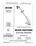
FULL ONE YEAR WARRANTY ON SEARS CRAFTSMAN GAS WEEDWACKER
If this CRAFTSMAN GAS WEEDWACKER ®trimmer fails toperform properly due to adefect in materia! or workmanshipwithin
one year of purchase, Sears will repair it, free of charge.
_fthis _RAFTS"_AN GAS _EE _A_KER_
trimmer is usedf_r c_mmercia_ _r rentaI purp_ses thiswarranty c_vèrage app_ies
for only g0 days from the date of pumhase.
, -, --" "WARRANTY SERVICE IS AVAILABLE BY CONTACTING THE NEAREST SEARS SERVICE CENTER/DEPARTMENT
THROUGHOUT THE UNITED STATES.THIS WARRANTYAPPLIES ONLY WH EN THIS PRODUCTtS IN USE IN THE UNITED
STATES.
This warranty gives you specific legal rights, and you may also have other rights which vary from state to state.
SEARS, ROEBUCK AND CO. / DEPT. 698/731A / SEARS TOWER / CHICAGO, IL 60684
/
,
-
•
,
.....
•
t
t
,
,
•
/
,
i
,
TABLE OF CONTENTS
Safety Rules and Precautions ...................
Know Your WEEDWACKER ® Trimmer .............
Assembly
Engine Information ............................
A. Fueling Your Unit ..........................
B. Pre-operation Checks .......................
C. Starting Instructions ........................
D. Operating Instructions ......................
E. Engine Adjustments ........................
Using Your Unit ..............................
A. Operating Instructions .....................
B. AdvancingThe Cutting Line .................
3
4
5
6
6
7
7
9
9
10
10
10
C. Cutting Methods ..........................
D. Cutting Head Maintenance ..................
General Maintenance .........................
A. Drive Shaft Lubrication .....................
B. Air Filter Care ............................
C. Fuel Tank Upkeep .........................
D. Starter Rope Repair .......................
E. Trouble Shooting Chart .....................
Accessories ................................
Parts List ................................
Quick Reference Page ........................
11
12
14
14
14
14
15
16
17
!8-24
27
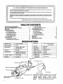
SPECIFICATIONS
ENGINE"I_PE:
2-CycleAir-Cooled
DISPLACEMEN'£
26.2cc
ENGINE RPM:
Operatingo6500- 7500
Idle- 2800- 3200
IGNITION:
SolidState
CARBURETOR:
DiaphragmAllPositionwith
adjustablefuel mixturejets
"ON/OFF' SWITCH:
PositiveToggle
STARTER:
Auto Rewind
MUFFLER:
LoTone- California approved
spark arresting
CLUTCH:
Centrifugal
FUEL TANK:
16.9fl. oz.
SPARKPI"UG:
STD3"6i258((_J-14)
SPARKPLUG GAP:
.024"/.02t_"
MODULEAIRGAP:
,010't/,014
LUBRICATION:
cUTrlNG LINE
DIMENSION:
"
. Gasoline/OilMix- 16:1
.080" Diameter
Assist Handle
Drive
"ON/OFF"
Shaft
Housing
Muffler Guard
Switch
Starter Rope
Throttle Trigger
Cutting
Head
Splash Deflector
Injector Button
Starting Inst
Model Number
Fuel Cap
Filter
MANUFACTURED UNDER ONE OR MORE OF THE FOLLOWING
U.S. PATENTS:
3,708,967; 3,826,068; 3,859,776; 4,035,912;
4,052,789;
4,054,992;
4,067,!08;
4,I04,797;
4,114,269;
4,124,938;
4,156,312;
4,156,967;
4,161,820;
4.167,812;
4,269,372;
4,296,675;
DES. 249,630;
DES.
255,764; DES.
260.394,
U.S. AND FOREIGN PATENTS PENDING.
SAFETY
Failure
KNOW
AI
RULES AND PRECAUTIONS
to follow safety rules and precautions
YOUR
UNIT
could result in serious personal
De
1. Read your Operator's Manual carefully until
you completely understand and can follow
all safety rules, precautions and operating
instructions before operating the unit.
PLAN
AHEAD
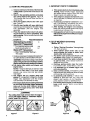
Always wear eye protection. The
splash deflector/line iimiter will not
prevent rocks and debris from being
thrown or ricocheting into the eyes
--and face which can result In loss of vision or
serious personal injury.
2. Dress safely in long pants and wear boots or
safety shoes. Do not wear loose clothing,
jewelry, short pants or sandals; or go barefoot.
3. Do not operate the unit when you are tired,
ill, or upset; or if you have taken alcohol or
drugs/medication.
4. Inspect the area to be cut before starting the
unit. Remove all debris and objects that can
ricochet,be thrown, become entangledinthecutting
head, or cause injuryor damage during cutting.
5. Keep children, bystanders and animals a safe
distance away from the work area -- a minimum
of 30 feet (10 meters).
1.
C.
HANDLE
FUEL
WITH
CAUTION
1. Eliminate all sources of sparks or flame (ineluding smoking, open flames, or work that
could cause sparks) in the areas where fuel
is mixed, poured, or stored.
2. Mix and pour fuel in an outdoor area; store fuel in
a cool, dry, well-ventilated place; and use an
approved, marked container for all fuel purposes.
3. DO .n_oLsmoke while handling fuel or while
operating the unit.
4. Wipe up all spills before starting the eng'ine.
5. Move at least 10 feet (3 meters) away from
fuel and fueling site before starting the
engine.
i_WAR
NI NG
The lower unit of this machine is designed as a line
trimmer only, and must not be equipped with any type
blade. Serious injury can occur to the user or
bystanders because:
The necessary protective devices for blade use are
not part of-the lower unit.
-- Some blades are not designed for the high speed
this engine produces. This can cause Injury due to
blade failure.
Do not use any attachment with this engine other than
those supplied by the manufacturer and specifically
recommended for this power head. Serious injury to
the user or damage to the engine can result otherwise,
YOUR
UNIT
SAFELY
1. Inspect the entire unit before each use for loose,
missing or damaged parl_Do not use until the unit
isin proper workingorder.
2. Use only flexible, non-metalic, monofilament
cutting line. Do notuse othermaterialssuch as rope,
wire,etc. Wire can break off during cutting and be come a dangerous missile.
3. Make sure the cutting head stops turning
when the throttle trigger is released and the
engine runs at idle speed. For correction,
refer to "Carburetor Adjustments,"
page 9.
4. Keep the handles free of oil and fuel.
5. Never start or run the engine inside a closed
room or building. Exhaus[ _LJmes contain
dangerous carbon monoxide.
.
Keep your body clear of the cutting head
while the unit is in use.
7. Do not operate in a position over waist high.
8. Do not overreach. Keep firm footing
and
balance at att times.
9. Run the engine at full throttle only when
cutting.
10. Stop the engine before removing the fuel
cap.
11. Use only for jobs explained in this manual.
2 Restrict your unit to users who understand
and follow all safety rules, precautions, and
operating instructions found in this manual.
B.
OPERATE
injury.
El
MAINTAIN
YOUR
UNIT
PROPERLY
1. Maintain the unit according to recommend.
ed procedures.
2. Disconnect spark plug before performing
maintenance except for carburetor adjustment.
3. Use only recommended replacement •parts.
The use of any part, or accessory not specifically
designed forthis unit could create a hazard and/or void
your warranty.
4. Drain fuel from the fuel tank before storing
for 30 or more days.
5. Do not store theunit or fuel in a closed area
where fuelvaporsocan reach sparks or an
open flame from hot water heaters, furnaces,etc.
6. Store in a dry ar.ea out of the reach of
children.
STATE AN D LOCAL
ORDINANCE REQUIREMENTS
Your engine is equipped with a temperature limiting
muffler and spark arresting screen which meets the
requirements of California Codes 4442 and 4443. All
U.S. Forest Land and the states of California, Maine,
Oregon, and Washington require bylaw that certain internal combustion engines operated on forest, brush, and
grass covered areas be equipped with a temperature
limiting muffler and/or spark .arresting screen. If you
operate an internal combustion engine in a state or
locale where such regulations exist, you are legally
responsible for maintaining the operating condition of
these parts. Failure to do so can subject you to
liability or to a fine.
KNOW YOUR WEEDWACKER
A. INTRODUCTION
® TRIMMER
B. UNPACKING
Your WEEDWACKER ® Trimmer is a versatile product
developed for large lawns and to make short work of a
variety of lawn care tasks - trimming, mowing, edging,
sweeping, and scalping.
°
,
INSTRUCTIONS
Remove contentsfrom the Carton if you have not
done so.
Check parts against the list below.
3 Examine parts for damage.
Special Features include:
•
•
•
•
•
4 Notify your Sears Store immediately
is missing or damaged.
FUEL INJECTION STARTING"
Adjustable assist handle
Semi-automatic advancing line feed
17" inch cutting path
Total weight -13 ibs.
-
ff a part
NOTE: A rattle like noise in a powerhead with an
empty fuet tank is a normal condition, caused by the
filter moving against the wall of the empty tank.
..
,,'L__m
10
KEY
1
2
3
4
5
6
7
8
9
10
11
12
13
14
15
CARTON CONTENTS:
'" QTY.
Engine
1
Drive Shaft/Bearing Assembly
1
Splash Deflector
1
Cutting Head
1
Assist Handle
1
2-Cycle Engine Oil - 8 oz. can
1
Grease
1
Loose Parts Bag
1
LOOSE PARTS BAG CONTENTS:
Screw, Splash Deflector- 114-10x1-1/8"
2
Bracket, Splash Deflector
1
Hex Bolt, AssistHandle, 114-20x1-1/2"
1
Washer, Assist Handle, 1/4fiat
1
Knob, Assist Handle, 114-20
1
Clamp - Engine Shroud
1
Screw- Clamp - 1/4- 20 x 9/16"
1
Nut - 1/4- 20 - Clamp
Operator's Manual (not shown)
1
ASSEMBLY
A. PREPARATION
ASSEMBLYSTEPS
Your Operator's Manual has been developed to help
you assemble the unit and to understand its safe operation. It is important that you read your manual completely to become familiar with the unit before you begin
assembly.
I. READ YOUR OPERATOR'S MANUAL.
2. Tools you will need:
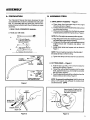
1. DRIVE SHAFT HOUSING
-- Figure 1.
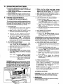
a. Place clamp from loose parts bag on the engine
shroud as shown in Figure 1.
b. Pull about 6 inches of the flexible drive shaft out from
the drive shaft housing.
c. Fit the end of the flexible drive shaft into the squareshaped opening insidethe engine shroud. Figure 1.
NOTE: Turnthe engine as necessarytoline upparts.
a:
/
Z" 1-1/4inch Wrench
7116 inch Wrench "
3/8 inch Wrench
or
Z
b.
_
_
d. Align the groove in the drive shaft housing with the
key inside the engine shroud opening.
e. Firmly push the drive shaft housing straight into the"
engine shroud until it bottoms out (about 1-1/2
inches).
f. Install clamp screw and square nut as shown in
Figure 1.
Adjustable Wrench
_
Slotted Screwdriver
NOTE: The nut must be mounted on the tab side of
the clamp to keep nut from turning.
CLAMP
DRIVE SHAFT
___J ._
g. Tighten the clamp screw secu rerywith a screwd river.
__
2. CUTTING
.o'ovo
HEAD -- Figure 2
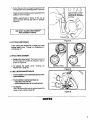
a. Hold the dust cup with a 1-1/4"wrench to keep the
dust cup from turning. Figure 2.
b. Thread the cutting head clockwise onto the arbor
shaft, against the dust cup, and as tight as possible
with your hand. Figure 2.
c. Press the tap button and pull the cutting line from the
head a minimum of 2 inches. Figure 3.
L.
Figure 1
1-1/4"
WRENCH
NOTE: To remove the cu_ing bead, hold the dust cup
.... with at-l/4"-wrench
and unthread the cutting head
counterclockwise &[_,_ .
Approximately2 inchesof line
canbe advanced each time the
DI RECTI ON
TO INSTALL
ARBOR
SHAFT
DUST CUP
Figure 2
Figure 3
3. SPLASH
DEFLECTOR
4. ASSIST HANDLE
-- Figure 4
a. Locate the raised "V" ridge on the splash
deflector into the indented "V" slot on the
drive shaft housing. Figure 4.
b. Rest the bottom of the splash deflector on top
of the drive shaft housing shoulder above the
dust cup.
NOTE: The bottom of the splash deflector
must rest on top of the shoulder of the drive
shaft housing.
c. Make sure the splash deflector is aligned
toward the:engine as shown in Figure 5.
d. Install the bracket and screws as shown in
Figure 4.
e. _Tighten the screws evenly and secu rely with a
3/8 inch wrench or a slotted screwdriver.
NOTE: It is possible that a small space will be seen
between the bracket and the splashdeflector when
iii
.... iiiiililli ¸• •
iiiiiiiiii
ii
i
ii
-- Figure 5
a. Align the assist handle onthe drive shaft housing above the decal(s), making surethe handle
curves back toward the engine. Figure 5.
b. Firmly push the assist handle over the drive
shaft housing.
c. Install the assist handle bolt, washer, and
knob as shown in Figure 5.
NOTE: Makesure the screwisplaced on the sideof
the handle with the hex-shaped screw opening,
d. Holdthe unitinthe operatingPositionand adjustthe
handle upor downthe'drive Shafthousingtoa posi,tion comfortablefor the user.
e, Tighten theknobby hand only, +.;+. .....
NOTE: The assist handle can be rotated from left to
rightallowingthe cuttinghead tobe tilted.Tilting the
angle ofthe cuttinghead is usefulwhen trimmingor
iiii
"""I=IIHIIII
I
+
""111
I
L
WASHER-(1/4-FLAT)
I14-10X1-I18" ,++ :-_
"
l
R=O
BOLT - (1/4-20x1-1/2")
'_.__._.S_,.-,,
"--v SLOT
+
ii
+
-. s.ouLoE.
.....
DUS T CUP
iiii
_ SPLASH DEFLECTOR
,, ......
III
Figure 4
Figure 5
ENGINEINFORMATION
A,: FUELINGYOUR
'
+i
UNIT
''
....
_:_ _ :+
....
;: "
1. FUEL MIXTURE
,
.
_ .
:
a.
DONOTUSE:_
_..._'
.
•,e•BIAOIi.:[Boating-lnStitUte
require_;:_ifuel mixture Of regularunleaded gasoline and a high qualltyengine oil specially made for
2-cycleair-cooled engines. The internaldesignofthe
2-cycleengine requireslubricationof moving parts,This .....
!ubric=i0 n isp[0videdwhen you usethe recommended
mixture of gasol ine and oil.
Using the correct measure of gasoitne to oll is very
important. Too much oit in'the mixture will foul the
sparkplug.
ICAUTION: I Too little oll will cause the engine to
overheat and become seized. _
Always mix the fuel thoroughly in a container since
the gasoline and oil do not readily combine. Do not
tryto mix fuel directly in the fuel tank.
6
•
•
_of+Amei+ic_) +
Does not have proper additives for air-cooled
2-cycle engines and can cause damage to your
unit.
..............
AUTOMOTIVE
OIL -.
.'
;
--Does not haveproper additives for 2-cycle
engines and can cause damage.
•
GASOLINE CON;rAINING
ALCOHOL
(High Test, Premium or Gasohol) --- Stiffens critical carburetor fuel metering
elements and causes engine damage
from _overheating. + '
-- Increases vapor lock (causes hard starting).
-- Attracts watercausmg
corros=on_damage
b. USE
THE
FOLLOWING:
3. IMPORTANT
POINTS
TO REMEMBER
a. Use only recommended
fuel mixtures.
M
1GALLON
REGULAR
UNLEADED
GASOLINE
b.
+
--OR--
=
Eliminate all sources of sparks or flame in
the areas where fuel is mixed, poured, or
stored. There should be no smoking, open
flames or work that could cause sparks.
Use an approved, marked container for all fuel
purposes.
C.
2. HOW TO MIX FUEL AND FILL TANK
-a. Pour 112gallon gasoline into an approved marked
container. Do not try to mix fuel directly in the fuel
tank.
b. Add entire measure of 2-cycle engine oil.
c. Cover containertightly and shake for one minute.
d. Add remainder of gasoline.
e. Cover containertightly and shake again.
f. Remove the fuel cap. Refer to "Specifications", page
2, for fuel cap location.
g. Fill the tank using a spout or funnel.
h. Reinstall the fuel cap securely.
B. PRE-OPERATION
d,
Mix and pour fuel in an outdoor area. Store fuel
in a cool, dry, well-ventilated place. Gasoline
vapors are harmful to your health and can cause
serious hazards, such as explosion and fire.
e,
Wipe up all fuel spills before starting the
engine.
f.
Move at least 10 feet (3 meters) away from fuel
and fueling site before starting the engine.
CHECKS
Before operating your unit, always:
,
1. v, CHECK OVER SAFETY RULESAND PRECAUTIONS in this Operator's Manual. Make certain you
completely understand and follow e&ch one.
2. _, CHECK THE AtR FILTER
Clean the filter if dirty before operating the unit. For
location, see page 14.
C.
STARTING
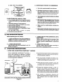
1. HOW
_-CHECK THE FUEL TANK.
Fill with a clean, fresh fuel mixture according to
instructionsin fuel mixturesection.
INSTRUCTIONS
FUEL INJECTION
STARTING
TM
WORKS
FUEL INJECTION STARTINGTMprovides
a
quick, start feature by. injecting
a precise
amount of fuel .directly
into the. carburetor
manifold which provides a rich fuel mix for the
first few seconds of operation.
INJECTOR
4
v-CHECK THE UNIT FOR LOOSE BOLTS, NUTS,
OR FITTINGS.
Tighten, repair or replace parts as necessary. Tools
required are shown on page 5. Use only recommended, genuine Sears/Craftsman replacement
parts.
BuI-r ON
- . • Each-time the injector button is pressed and
-.+.:_- ---released, fuel is forced'from'the
fuel tank to
'- the accumulator c:hamber.
• The accumulator chamber provides a secondary fuel supply until the carburetor can
obtain fuel through the primary line
• When the accumulator chamber is full, fuel
is injected into the carburetor manifold to
provide a rich mixture for starting.
Excess fuel escapes through a drain to
prevent the engine from flooding
if the
injector button is pressed too many times.
As a result, a few drops of fuel may appear
on the ground during the starting procedure.
CARBURETOR
DRAIN
FUEL INJECTION STARTING DEVICE (PATENT PENDING)
Figure 6
The number of injections
required
will
depend on temperature conditions and the
time elapsed since the engine was last
started.
2. STARTING
3. IMPORTANT
PROCEDURE
a. Extenda minimumof4inchesoflinefromthe
cutting head to provide the correct load on the
engine.
b. Stand in the operating position, and place
the cutting head on the ground. Figure 9.
This insures that fuel will flow into the injector pump.
c. Move the ignition switch to the "ON" position. Figure 7.
d. Grip the rear handle with your right hand,
squeezing and keeping the throttle trigger
fully depressed
until the engine runs
smoothly.
e. Press the injector button down fully allowing the button to return completely after
each pressing. Follow conditions and injections listed.
Conditions
POINTS TO REMEMBER
a. If the engine starts to die immediately after
starting, keep throttle trigger depressed
and press injector button once with forefinger to give unit additional fuel.
b. If the engine is stopped momentarily (less
than 5 minutes), it probably will not require
an injection.
c. If unit runs out of fuel or is drained for storage "First Starting" procedure may be required because the system will be dry.
d. After starting and engine runs smoothly,
keep unit running at half speed until engine
is warmed up to proper idle.
e Usinggasoline orfuelmix over2 months old
will cause the engine to be difficult or impossible to start!
Required Injections
I First Starting Out-of-Box
6
[ -
[ Above 30°F Temperature_
-- First starting/engine
cold
-- Restarting/engine
hot
3-4
0-1
{ Below 30°F Temperature ]
-- (See "Cold Weather Starting",
this page.)
f. Continue pressing and releasing the injector button untilfuel drips out of the bottom of the unit.
[ CAUTION: ] If more than a drop ortwo of fuel
spills on the ground move unit away to another
area for starting to avoid creating a fire hazard.
g. Pull starter rope quickly and sharply until
engine starts.
NOTE: If engine attempts to start but dies
or does not start after 5 (five) pulls, press
injector one more time and pull starter
rope again.
h. The engine will run roughly when first
started. It is important to keep the throttle
trigger fully depressed until the engine
runs smoothly (10 seconds or less)
i. If theengine starts but the cutting head does
not tum with the throttle trigger depressed,
make sure the drive shaft housing is properly
seated in the engine shroud. See "Ddve Shaft
Housing", page 5.
4. COLD WEATHER
(Below 30 ° F)
STARTING
a. Follow "Starting Procedure" through step
"d", then as below.
b. Press injector button down fully six (6}
times allowing the button to return completely after each pressing.
c. Pull starter rope quickly and sharply until
unit starts. Keep trigger fully depressed.
d. If unit does not start in four pulls or attempts
to start but dies, press injector button an
additional four times.
e. Continue pulling starter rope four pulls.
If unit fails to start, repeat step d., above.
f. It is important not to release trigger until
unit runs smoothly.
g. Once unit has started, immediately press
injector button two additional times to keep
unit running until it warms up.
h. in extremely cold weather, it will be very
difficult to flood the unit, so if the unit
doesn't start-quickly, do not hesitate to
press injector button for additional fuel.
i. For starting warm engine in cold temperatures, press injector button once before
starting.
/_WARNING
The cutting head must not turn when the engine
runs at idle speed. Refer to "Carburetor Adjustmerits", page 9 for correction.
FuEL
INJECTOR
BUTTON
Figure 7
Figure 8
Figure 9
D=
OPERATING
INSTRUCTIONS
For maximum performance and efficiency:
1. Always accelerate the engine to the desired
speed before cutting.
2, Never operate the engine at a higher speed
than necessary.
3. Always release the trigger and allow the engine to return to idle speed when not cutting.
Sm
4. Make sure the cutting head stops turning
when the throttle trigger is released and the
engine runs at idle speed, For correction,
refer to "Carburetor Adjustments,"
below_
5. Stop engine by moving the ignition switch to
the "OFF" position (Figure 8).
ENGINE
ADJUSTMENTS
1. CARBURETOR
ADJUSTMENTS
C.
The carburetorhas been carefully adjusted atthe factory.
Due to changesin altitude and operating conditions, your
carburetor may require adjusting. To make the adjustment follow the procedure below very carefully:
a. PREPARATION
1.) Use fresh fuel mix with proper gasoline/
oil ratio. See "Fuel Mixture", page 7.
2.) Make sure the cutting line extends at least
4 inches to provide correct load on engine.
3.) Remove
air filter ( Figure 10) and place
under spark plug wire for safe keeping_
4.) Turn both tow speed and high speed mixture
screws clockwise
_
untilfully closed,
but do not overtighten. Figure 10.Unscrew beth
mixture screws one full turn counterclockwise
b.
IDLE SPEED ADJUSTMENT
1 .,) Turn Idle Speed Screw clockwise
until it stops. Do not overtighten. Open
screw one full turn counterclockwise.
2.) Start the engine and cut grass for 3 minutes to warm up engine.
3.) Allow engine to idle.
4. ) AdjustIdleSpeed Screw untilengine continues
to run without stalling and without the cutting
head turning.
Turn
Turn
d. IDLE SPEED ADJUSTMENT
1 .) Allow engine to idle.
2.) Adjust the Idle Speed Screw until the
engine idles as fast as possible without
the cutting head or blade turning
E-CAUTION:] Do not operate engine at full throttle
for prolonged periods while making high speed
adjustments as damage to the engine can occur.
e. HIGH SPEED MIXTURE
ADJUSTMENT
1 ) Support the shaft so that the cutting head
is off the ground and will not contact anv
object.
2.) Squeeze throttle trigger wide open
3.) Turn the High Speed MixtureScrew slowly
clockwise _
until the engine speed is
reduced. Note position.
4.) Turn the screw slowly counterclockwise
_'"_.
Stop when the engine just begins
to run rough.
,.5.) Turn the screw
slowly.-the
minimum
amount-clockwise--_p--']l=
until the engvne
runs smoothly.
screw
clockwise
_
to increase
- engine speed if engine Stalls;
screw counterclockwise
-_k'.,_ to slow
engine down if cutting head
continues to turn.
f.
l CAUTION: JHigh and low speed mixture settings
are highly critical adjustments. If set incorrectly permanent damage will occur to the engine, Both the
low speed mix and the high speed mix screws
should be in the range of 3/4 to 1-1/4turns open.
LOW SPEED MIXTURE ADJUSTMENT
1 .) Allow engine to =die.
2.) Turn Low Speed Mixture Screw clockwise _
slowly. Note the position at
which the engine speed is increased.
3.) Turn the screw slowly countercfockwise.
JP.,_.
Note the position at which the
speed is reduced.
4.) Set the screw mid-way between these two
extreme :positions.
CHECK ACCELERATION
Allow the engine to idle. Squeeze trigger and
check engine acceleration.
If the engine
does not accelerate smoothly, you may have
to repeat steps "b.3.)" through "e."
NOTE: Generally, by turning the low speed
screw counterclockwise
_
a small amount,
the unit will accelerate properly.
g. REINSTALL AIR FILTER
tCAUTION: I The air filter must be fitted into the
corners of the housing to avoid engine damage.
2. SPARK PLUG
Check spark plug periodically and replaceas necessary.
Set the electrode gap at .025".
Figure 10
9
USING YOUR UNIT
Your Trimmer is equipped with a semi-automatic advancing
cutting head that cuts with the tip of a monofilament nylon line.
The nylon cutting line will easily remove grass and
weeds from around walls, fences, trees, and flower
beds, but it also can cut the tender bark of trees or
shrubs and scar fences. For this reason, it is very
important to learn the proper techniques of cutting
around and near objects.
The nylon cutting line will wear faster and will
require being advanced more frequently when you
are cutting against rocks, bricks,concrete, metal fences,
etc., than against trees or wooden fences.
The cuttinghead
--if
will wear prematurely:
allowed to continuously
during normal cutting.
contact the ground
A. OPERATING
1. Read your Operator's Manual.
Make certain you completely understand and follow
all safety rules, precautions, and operating instructions before operating the unit.
,
4. Check the unit before operation.
Lookfor worn, loose, missing,or damaged parts. Do not
use until the unit is in properworking order.
,
B. ADVANCING
THE CUTTING
Inspect the area to be cut.
Remove all debris and objects that can ricochet, be
thrown,become entangledinthe cuttinghead orotherwise cause injuryor damage during cutting.
6. Keep observers, children, bystanders, and animals
safely away.
Beforestarting the engine and during operation,make
certainchildren,animalsand bystandersare awayfrom
the work area - a minimum of 30 feet (10 meters).
LINE
• The cutting line is extended semi-automatically by
tapping thebottom ofthe head on the ground with
.the engine_running.
k.• Approximately 2 Inches oflinelsextended
each
time the tap button is tapped on the ground,
• The line,miter on the splash deflector cuts line to
a maximum allowable length.
• The most efficient cutting line length Is the maximum length allowed by the line Iimiter.
1. To advance line:
a. Operate the engine at fullthrottle.
b. Hold cutting head parallel to and above the
grassy area of the ground.
c. Tap the cutting head lightly on the ground one
time. See Figure 12. Approximately 2 inches of
line will be advanced after each tap.
NOTE: If the line is worn down to two inches or
less, more than one tap may be required to
obtain the most efficient line cutting length.
10
Always wear eye protection. The
splash deflector/line limiter will not
prevent rocks and debris from being
thrown or ricocheting into the eyes
and face which can result in loss of vision or
serious personal injury.
3. Dress safely in long pants-and wear boots or
safety shoes.
Do not wear Iooseclothing, jewelry, short pants or
sandals; or go barefoot.
--if the line limiter is not kept sharp.
WARNING
Use only flexible, non-metalic, monofllament cutting
line. Do not use other materials such as rope, wire, etc.
Wire can break off during cutting and become a
dangerous missile.
INSTRUCTIONS
2. Always keep the splash deflector in place when
the unit Is being operated.
- 3. Keep the line Iimitersharpfor fast, easycut-off.
See page 13for sharpening instructions.
NOTE: Always tap the cutting head on a grassy
area of the ground. Tapping on surfaces such
as concrete or asphalt can cause excessive
wear to the cutting head.
LINE
LIMITER
CUTS EXCESS
LINE
CUTTING LINE,
TAP LIGHTLY
ON GROUND
ONE
TIME
TO ADVANCE
-q
C. CUTTING
METHODS
• The tip of the line does the cutting. Allow the unit
to trim at its own pace. You wilJachieve better results
by not crowding the line into the cutting area. The right
way and wrong way are shown in Figure 13.
• Always cut left to right,
.
TRIMMING -- Figure 14
Hold the cutting head at a 30 degree angle to the
cutting area for efficient trimming. Do not force the
cutting line intothe work area. Allow t.hetip ofthe line
to do the cutting.
ii
'- \
RIGHT
,
_WRONG
I
iii
i
Figure 13
_WARNING
Always wear eye protection. Never lean over the
cutting head. Rocks or debris can ricochet or be
thrown into eyes and face and cause loss of
vision or serious personal injury.
J
2, EDGING -- Figure 15
Adjust yourtrimmer for edging byturningtheengine
upside down so the drive shaft housing angles out
rather than down. Rotate the assist handle on the
shaft, placing it in an up, usable position. Hold the
cutting head above the area to be edged as shown
and operate the throttle trigger with your thumb,
3. MOWING -- Figure 16
Yourtrimmeris idealfor mowing in places conventional
fawnmowers cannot reach. Inthe mowingposition,the
cuttinglineisparallelto theground.Avoidlettingthe cutting head continuously contact the ground as this can
cause damage toyourunitas well as scalp the ground.
4. SCALPING -- Figure 17
To remove unwanted vegetation around trees, posts,
monuments, etc., maintain a 30 degree angle with the
cutting head and allow the tip of thecutting line to
strike the ground.
p
NOTE: Increased line wear is to be expected when
using scalping techniques.
\',,
,
TRIMMING
i i
Figure 14
SWEEPING -- Figure 18
For quick and easy clean up extend the line to the
length allowed by the line limiter and move the unit
from side toside, keeping the cutting head parallelto
the surfaces being swept•
Figure 15
Figure 16
Figure 18
11
D.
CUTTING
HEAD
1. CUTTING
MAINTENANCE
NOTE: The aluminum line saver is reversible. After a groove is worn into one side,
reverse the line saver (with the spool
removed) to provide a new wear surface.
Figure 21.
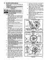
LINE REPLACEMENT
a. Hold the cutting head as shown in Figure 18.
Press the lock tab, and turn lock ring counterclockwise
b. Remove the lock ring,
spool. Figure 19.
tap button,
and
e°
c. Clean dirt and debris from housing and
spool.
d. Inspect spool. Replace as necessary. See
instruction #3 this section.
i
i
i
i
i
i
PressLock Tab.
Turn outer ring
counterclockwise,
Replace a worn spool with a new pre-wound
spoolfor quickeasy replacement. Or as an alternative, replace nylon line on existing, usable
spool.Toreplaceline, insert1/16to 1/8 inchof the
end ofthe linethroughthe holeinthe spool.Wrap
the line evenly onto the spool in a clockwise
directionas shown by arrow on spool.
Figure 20.
f. Insertthe end ofthe line through the line saver as
shownin Figure21. Push spoolin housing.Force
spooldown. Turnand lock spoolunderthe drive
lugs on the drive gear.
\l
l
g. Replace the tal_ button; press lock tab and
install the lock ring. Turn the lock ring
clockwise _
and fasten under the
catches on the housing. Figure 22. Check
to be certain all catches are properly secured.
LOCK TAB
Figure 18
,=,,i
ii
ii
TAP BUTTON
U$1NG
Figure 19
Figure 21
!
I
I
I[11 II
I
Turn Lock Ring
clockwise to install,
\
12
Figure 20
Figure 22
h.
in
Pull on the nylon line to change the spool from the
lockedposition to the operating position. Figure 24.
Approximately2 inches
of line canbe advanced
eachtime the Tap Button
Obtain correct line length by pressing tap button and
pulling on nylon line again.
is pressed.
NOTE: Approximately 2 inches of line can be
advanced each time the tap button is pressed.
Figure 24.
USE ONLY SEARS/CRAFTSMAN
REPLACEMENT
PARTS
®
TAP BUTTON
2. CUTTING
Figure 24
LINE REPAIR
• If the cutting line breaks off or backs up in the
cutting head, follow "Cutting Line Replacement",
omittingstep "e".
3. SPOOL REPLACEMENT
a Replace the spool when: The square corners of
the drive lugs are rounded off, reduced in size, or
broken off. Figure 25.
b. To replace the spool, follow "Cutting
Replacement" (page 12).
Line
WORN SPOOL
NORMAL SPOOL
i
ii
Figure 25
4. LINE LIMITER
MAINTENANCE
• The line limiter is the metal blade found on the
splash deflector.
_-Theline-limiter
must be kept sharp to:
-- allow fast, easy cut-off.
avoid excessive wear to the cutting head.
•• To sharpen:
Use a fiat file and file from the outside toward the
inside of the line limiter,Figure 26.
Figure 26
NOTES
13
GENERAL
A.
DRIVE
MAINTENANCE
SHAFT
LUBRICATION
NOTE: Check the Flexibie Drive Shaft for
wear or damage, Replace if broken wires,
twists or kinks are found.
• Lubricate the Flexible Drive Shaft:
-- After each ten (10) hours of operation:
-- Before operating if the unit has been stored
for 90 days or longer.
ICAUTION:tLay the Flexible Drive Shaft on a
clean surface. Avoid laying the shaft on the
floor, ground or on any surface that may have
dirt or debris. Even after wiping the shaft,
grease residue can pick up dirt particles that
can cause damage or premature failure.
• Use gear grease stock #28-59071.
NOTE: A tube ofgrease has been suppliedwith your
unit to be used after the first 10 hours ofoperation.
• Observe
results:
the following
procedure
for best
3. Using a clean cloth, thoroughly wipe the surface of the Flexible Drive Shaft to remove any
old grease that may be present/
4. Applya uniformcoat ofgear grease to the entire surface of the Flexible Drive Shaft. Figure 27.
5. Inject the remaining contents of the tube supplied with the unit into the top of the Drive
Shaft Housing.
6. Replace Flexible Drive Shaft in the Drive
Shaft Housing.
7. Follow the instructions on page 6 to replace
Drive Shaft Housing in the Engine Shroud.
CAUTION: IAvoid bodily contact with the muffler
area when the engine is warm. Always replace
the muffler guard if it becomes damaged or
broken.
1. Loosen the Pinch Clamp Bolt and remove the
Drive Shaft Housing from the Engine Shroud.
2. Remove the Flexible Drive Shaft as shown in
Figure 26.
Wipethe Flexible
ii i i
AIR
FILTER
CARE
A dirty air filter decreases engine
and increases fuel consumption,
Cll
performance
Clean the Air Filter:
• Frequently,
• Always after 5 tanks of fuel or 5 hours of operation, whichever is less,
Follow these steps:
1, Removetheairfilter(Iocatedatthebettom, rearofthe
Engine Shroud) see page 2.
2, Wash in soap and water.
14
iii
Figure 27
Figure 26
El
]1
ICAUTION:] Do not clean filter in gasoline
or other flammable solvent to avoid creating
a fire hazard.
3. Squeeze filter dry.
4, Replace the air filter.
I CAUTION: f The air filter must be fitted into
the corners of the housing to avoid engine
damage.
FUEL
TANK
UPKEEP
Never use gasoline that ismore than 2 months
old in a fuel mixture. Gasoline begins to break
down after a period of time and will form compounds that cause hard starting and damage in
2-cycle engines.
,
inspect the unit for fuel leaks each time it is
used. Repair or replace parts as necessary.
2. Using gasoline or fuel mix over 2 months old will
cause the engine to be difficult or impossible to
startl
.
Drain the fuel tank or allow the unit to run out
of fuel before storing for 30 or more days.
NOTE: "First Starting"
procedure
may be
required fora unit that runs out of fuel or from
which fuel is drained, See "Starting Instructions", page 8.
D.
STARTER
ROPE
REPAIR
• Repair the starter rope If the rope breaks next
to the pulley.
• Replace the starter rope if the rope breaks 2-3
inches away from the pulley as the rope will be
too short to repair properly.
/_WARNING
Always wear eye protection when servicing the starter rope. The recoil spring,
located beneath the pulley, is under tension. If the spring pops out, serious personal injury can result.
• To repair or replace:
1_
2.
3.
4.
5.
6.
7.
8.
NOT_ Use caution when separating the
fan housing from the shroud to avoid
breaking or damaging the fuel line fittings.
Drain all fuel from tank.
Remove the four (4) screws from fan
housing. Figure 28.
Carefully separate fan housing from shroudabout one (1) inch.
Disconnect fuel lines from fittings.
Disconnect ignition module wires. Figure
28.
Slide high tension lead grommet from slot,
in fan housing.
Separate the fan housing completely from
the shroud.
If the starter rope is not broken, release
the spring tension by pulling about 12
inches of rope from the pulley and catch
the rope in the notch as shown. Figure 30.
17. Hold the 12 inch slack in the rope and
catch rope in pulley notch. Figure 30.
18. Hold the rope taut and make 2 complete
turns
of the pulley counterclockwise
to place tension on the pulley.
Hold the pulley to retain tension.
19. Align pulley notc_ with rope exit hole,
pull starter handl_tothe
full extent of the
rope and allow the rope to slowly wind
around the pulley.
NOTE: While the unit is disassembled,
inspect the carburetor
housing seal and
replace if worn. Figure 28.
20. Reverse procedure for re-assembly of fan
housing to shroud.
NOTE: Make sure the fuel line with the
black stripe or solid color is installed on
i.i
GROMMET
MODULE
i
i
WIRES
SHROU[
CARBURETOR
HOUSING
FUEL LINE FITTINGS
i
FAN
3USING
LINES
ii
Figure 28
NOTE: The tension on thestarter spring
will be released if the rope has broken.
9. Remove screw and pulley very carefully.
Figure 29. The recoil spring which lies
beneath the pulley must stay in the housIng, flat against t6e bottom. Itthe spring Is
disturbed, it will require oonsiderable time
and effort to reinstall. Twist the pulley
gently clockwise ,,,,-]& ' as you pull up to
release the spring.
10. Moveawayfromthefuel tankand melttheend0f
the new rope to go intothe pulley,
11. Allowthe melted endtoddponce, then while rope
isstillhot pullthe melted end through a clean rag
to obtain a smooth, pointed end.
12. Insert rope through the rope exit hole in
the fan housing.
13. Guide rope insidepulley,then upthrough topside
pulley hole by pushing the rope from the underside hole with a small object such as a
screwdriver.
14. Wrap rope counterclockwise 4[--,, around
pulley ratchet and tuck loose end back
under-rope
leaving a 1/4 to I/2 inch
tail laying in the rope groove. Figure 30.
15. Wind all but about 12 inches of the rope
counterclockwise
_
around pulley.
16. Replace pulley in the housing. Be sure
the pulley is all the way down and the
spring is secured. Replace screw and
tighten. Figure 29.
IIGNITION
,o.,
,o.,
NOTCH
Figure 29
Figure 30
15
TROUBLE
SHOOTING
CHART
TROUBLE
Engine will not start
1.
2.
3,
4.
Ignitionswitch off.
Fuel tank empty,
Spark plug not firing.
Fuel not reaching carburetor,
5. Engine flooded.
6. Compression low.
Engine will not idle
properly
1. Idling speed set too low.
2. idle speed set too high.
3. Low speed screw requires adjustment.
I 4. Crankshaft seals worn.
5 Compression low.
Engine will not accelerate, lacks
power or dies
under a load
REMEDY
CAUSE
1.
2.
3.
4.
Carburetor requires adjustment.
Air filter dirty.
Spark plug fouled.
Carbon build-up.
5. Low compression.
1.
2.
3`
4.
Move switch'to"Start",
....
Fill tank with correctfuel mixture.
Installnewplug.
Check for dirty fuel filter; ctean. Check
for kinked or split fuel line; repair or
replace.
5. See Starting Instructions.
6. Contact your Sears Service Center.
,,,,,
........
1. Adjust idle speed screw clockwise to
increase speed.
2. Adjust idle speed screw counterclockwiseto reduce speed.
3. See Carburetor Adjustments.
4. Contact your Sears Service Center.
5. Contact your Sears Service Center.
1.
2.
3.
4.
See Carburetor Adjustments.
Clean or replace air filter,
Clean or replace Spark Plug and regap.
Clean exhaust system includingspark
arrestor.
5. Contact your Sears Service center.
Engine smokes
excessively
1. High speed needle requiresadjustment.
2. Air filter dirty.
3. Oil rich fuel mixture.
1. See Carburetor Adjustments.
2. Clean or replace air filter.
3` Empty fuel tank and refillwith correct
fuel mixture.
Engine runs hot
1. Fuel Mixture Incorrect.
2. Spark Plug Incorrect.
3. Carbon build-up.
4. High Speed Mixture set too low.
. See Fueling Your Llnit.
2. Replace with correct plug.
3. Clean exhaust system including spark
arrestor.
4. See CarburetorAdjustments.
1. Carburetor requires adjustment.
2, Clutch requires repair.
1. See Carburetor Adjustments.
2. Contactyour Sears Service Center.
Cutting head dobs not
tum when engine is
accelerated
1. Drive shaft not engaged.
2. Carburetor re_:luiresadjustment.
3. Clutch slipping.
Cutting head stops
:under e load
2.
1. See Assembly Instructions.
2. See Carburetor Adjustments.
3. Contact your Sears Service Center.
1. See Assembly Instructions.
.2, See Carburetor Adjustments....
! Unit engages at
idle speed
Cutting line does
not advance.
16
1. Drive shaft not engaged.
Carburetor requires adjustment.
& Clutch slipping.
1. Line improperlywound'ontospool,
2. Drive.gear damaged or worn.
3. Worn spool.
Contact .your Sears Se,rvice Center.
1. Rewind spool.
2, Replace drive gear.
& Replace spool.
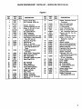
ACCESSORIES
A.
ACCESSORIES
2-Cycle Engine Oil ............................................
Stock No.
71-36555
Gear Grease (14-112oz.) ........................................
Stock No.
28-59071
Part No.
STD361258
Replacement Cutting Head .....................................
Stock No.
71-85764
Spool W/Line ................................................
Stock No.
71-85789
Nylon Cutting Line ............................................
Stock No.
71-85778
Shoulder Strap Kit ............................................
Stock No.
71-85783
Spark Plug ...................................................
NOTES
17
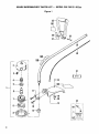
SEARS WEEDWACKER
® PARTS LIST --
MODEL 358.796131 -26.2cc
Figure 1
25
101
26
28
27
29
30
f
31
I
19
2O
14
10
18
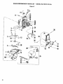
SEARS WEEDWACKER
® PARTS LIST m MODEL 358.796131-26.2cc
Figure I
KEY
NO.
PART
NO.
QTY.
RECL
1
706515
1
2
3
4
5
6
7
8 .......
9
10
93896
1
93898
1
92067
1
92068
1
93897
1
706502
1
9338? ..... 1
92133
1
92243
2
11
12
14
15
19
2O
"93653
93716
94440
15337
93853
STD
540410
1
1
1
2
1
2
DESCRIPTION
Cutting Head Assembley
Stock #71-85764 (Incl. 2-9)
Hub wlLine Saver
Line Saver
Spring
Adaptor- Spring
Drive Gear
Spool w/Une-Stock #71-85789
....ReleaseButton_
COVer
Screw-l/4-10xl-l/8-Splash
Deflector
Bracket- Splash Deflector
DustCup
Splash Deflector
Screw- 10-24xl - Line Limiter
Line Limiter
Nut- 10 - 24 - Locking
KEY
NO.
25
26
27
28
29
3O
_3_1_
32
Decals
-101
102
103
104
PAR'I:
NO.
10618
92059
STD
551025
STD
522517
94439
93936
3_0_1_02
66706
26593
27153
26674
26570
REQ.
1
1
I
DESCRIPTION
Assist Handle
Knob- 1/4- 20
Washer- 1/4- Flat
Hex Bolt-114-20x1-112
1
1
DriveShaft Housing
Rexible Drive Shaft
.....
G eajG re_e_Sto__k#28-590"£1....
Operator's Manual
i
Warning Label - Assist Handle
Decal - Warning (Shaft)
Decal - Weedwacker
Decal - Splash Deflector
1
1
1
Key No's Excluded: #13, 1618, 21.24.
19
SEARS
WEEDWACKER
® PARTS
LIST
Figure
-- MODEL
358.796131-26.2cc
2
21
24
J
I
I
t
I
I
6
]
11
36
(
I
!
!
43
-35
20
SEARS WEEDWACKER
® PARTS LIST -- MODEL 358.796131-26.2cc
Figure
KEY
NO.
1
2
3
5
6
7
8
PART
NO.
QTY.
REQ,
24436 i:
26566
26567
24365
24371
23575
STD
6108O7
69182
1
1
1
1
1
1
1
9
15706
10
11
24569
15582
1
2
12
13
24461
15367
1
5
14
15
16
26109
21052
10729
1
1
1
18
19
20
21.
22 _
- 23
24
22290
21053
26931
69178
42067
26035
15544*
1
1
1
1
1
1
2
25
26048
DESCRIPTION
Bumper Fuel Tank Housing
Handle & Fuel Tank Housing
Handle Cover
_igger- Throttle
Air Filter
Nut- Grounding Switch
Screw - 8 - 16 x 3/4 Pan Head Handle Cover
K'rt-Grounding Switch
(Inc1.#6,10& 39, this page
and #12 from page 23)
Screw- 10- 24 x 1 - 1/2- Sems
Fan Housing - Top
Washer- Ground Terminal
Screw- 10- 24 x 5/8- Seres
Fan Housing - Bottom
Trigger- Spring
Screw- 10-14 x 3/4- Fan
Housing to Handle & Fuel
Tank
Rlter- Fuel (Inlet Line)
Une- Fuel Inlet
FuelCap.Assembly
(Incl. O-Ring)
Rope (3.5 ft)
Line - Pump to Accumulator
Fuel Pick-Up Assembly
Fan Housing I_t
Starter Recoil Spdng
Air Baffle
Screw- 1/10x 3/8 Pan Hd.Air Baffle
Starter Pulley
2
KEY
NO.
PART
NO.
QTY.
REQ.
26
27
15123
15479
1
1
28
29
30
26O32
10738
16563*
1
1
1
31
32
33
26119
21054
26178
1
1
1
34
35
26549
10773
1
1
36
37
38
39
4O
41
15590
15669
26560
39122
15610
26792
2
1
1
1
1
1
42
STD
511010
15274
4
= -=
43
Decals
101
27153
26568
26569
4
1
DESCRIPTION
Washer#10 Starter PulleyScrew
Screw - #10 x 3/4 - Hex Washer
Head - Starter Pulley
InjectorButton
Pump Assembly(Inc1.#19)
•screw- #10 x 1 - 3/16 Plastite
Air Baffle I Pump Mounting
Check Valve - Duck Bill
Fuel Une - Tankto Accumulator
Clip - Retainer - Inlet Line Fuel Tank
Shroud
Fuel Tank Assembly(Incl. #14,
15,16,20,31,32&33)
Screw- 10 - 2 x 5/8 Binder Head
Screw-Pinch Clamp-1/4-20x9/16
Clamp
Lead Wire - Ground
Nut #12-24 Square
Ass'y.- Rope and HandleStarter (Incl.# 18)
Screw- 10 - 24 x 718- FiI. Hd.
Shroud
Washer- Flat, #10 Narrow
Shroud
Decal- Instructions
DeCal- Shroud (Right)
-(not shown)
• Decal - Shroud (Left)
_;(notshown)
*If yourunit has been serviced with the metal fan housing, use Part No. 15373 (Screw- #10 - 24 x 1/4- FiL Hd.), instead of 15544
(Key No.24), and Part No. 15305 (Screw - #10 - 24 x 1 - 3/1-6RI. Hd.), instead of 15563 (Key No30).
Key No'sExcluded: #17
21
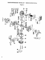
SEARS WEEDWACKER
® PARTS LIST -- MODEL 358.796131-26.2cc
Figure 3
1011-
7
51
52
4
9
7
53
54
16
35
22
57
58
SEARS WEEDWACKER
® PARTS LIST-
MODEL 358.796131-26.2cc
Figure 3
KEY
NO.
PART
NO.
QTY.
REQ.
2
I
Spring - Starter Dog
Nut - Flywheel - (5/16 x 26)
1
1
2
6
7
8
9
10
42059
STD
54I 131
15127
39114
STD
551 OO8
69181
19059
15168
1O316
39103
11
12
13
14
24435
25995
15235
1O677
1
1
2
1
15
19128
16
17
18
19
2O
15565
39082
3934
3933
STD
361258
15126
23373
26177
10651
2
1
1
1
1
Washer- Flywheel
Rywheel Assembly (Incl. #1)
Screw - 8 - 32 x 3/4 - Fil. Hd.Ignition Module
Kit - Ignition Module
Seal - Crankcase
Screw - Crankcase
Crankcase Ass'y.(Incl.#7& 28)
High Tension- Lead Assembly
(Incl. #17,18 & 19)
Grommet- Plug Wire
Electrical Tab
Screw- 8-18 x 9tl6
Cap Assembly- Accumulator
(Incl. Cap, Screen & "O"
Ring)
O-Ring-Accumulator
Chamber
Screw - 8-18x1'-'Accumulator
High Tension Lead Wire
Boot - Spark Plug
Connector- Spark Plug Lead
Spark Plug (CJ-14)
24302
1
15162
32058
15351
24438
2
2
2
1
1
2
3
4
5
21
22
23
24
25
26
:27
26
29
3O
1
2
4
1
1
1
1
1
1
DESCRIPTION
Key - Rywheet
Boot-Throttle
Throttle
Wire (Red)
Accumulator Assembly
(Incl, #14,15 &34)
Gasket - Cylinder
Ring - Piston
Retainer-Wrist Pin
.
Beadng- Crankcase
Washer- Thrust - Crankcase
Reed Valve
KEY
NO.
PART
NO.
31
19108
32
33
34
35
36
1
1
1
1
4
38
"39
19105
21055
19131
26047
STD
610805
STD
610603
23367
15239,.
40
41
42
43
44
45
46
47
48
12070
26949
24903
22198
32057
26675
26O46
19115
35183
1
1
2
1
1
1
1
1
1
49
15566
5O
51
52
53
54
24364
24361
24362
69196
69194
1
1
1
1
1
55
56
57
58
24932
24855
10797- 3O054
2
1
37
QTY.
REQ.
1
1
2
1''
DESCRIPTION
Gasket- Carburetor Case to
Crankcase
Seal - Carburetor Case
Fuel Line - Carburetor
O- Ring (Orifice)
Cover- Carburetor Case
Screw - 8 - 18 x 9/16 - Pan
Hd. - Carburetor Case Cover
Screw-6 - 19 x 5/15 - Pan Hal.Reed Valve
:Washer- Reed Valve Screw
,Screw- 114-20 x 3/4 - Hex
Socket Hd.- Cylinder
Cylinder
Diffuser- Muffler
Spring - Muffler Detachment
Piston Kit (Inc1.#26,27& Pin)
Bearing - Wrist Pin
Crankshaft & ROdAssembly
Carburetor Housing
Gasket- Carburetor
Carburetor- WA - 149 (See Page 24 for Assembly)
Screw - 10 - 24 x 2-1/4" Fil. Hd. - Carburetor
Screen - Spark Arresting
Cover- Muffler
Body- Muffler
Kit - Clutch Washer
Kit - Clutch Assembly (Incl.
Clutch Washer)
Spring - Muffler Guard
Guard - Muffler
Coupling & Bearing Assembly
_ Sealant- Crankcase
(Not Supplied With Unit)
23
SEARS
WEEDWACKER
® PARTS
CARBURETOR
LIST -- MODEL 358.796131-26.2cc
NUMBER
35183
Figure 4
KEY
NO.
PART
NO.
1
2
3
4
5_
6
7
8
9
10
11
12
13
14
15
16
35017
35191
35164
35156
35178
35166
35133
35007
35138
35015
35132
35023
35141
35106
35031
35o31
QTY'.
REQ.
1
1
1
1
1_
1
1
1
1
1
1
1
1
1
1
1
DESCRIPTION
*+
.
+
*+
+
+
+
+
Screw -"Pump
Cover
Pump Cover Ass'y. (Incl. #4)
Gasket- Pump
Screw- Idle Adjustment
Screen - Inlet
Diaphragm - Pump
Valve - Throttle
Clip - Throttle Shaft
Spring - Throttle Return
Screw - Throttle Valve
S haft Assembly - Throttle
Spring - Idle Needle
Needle - Idle
Spring - Metering Lever
Valve - Inlet Needle
Lever- Metering
Conteht_ of Gasket/Diaphragm
+Contents of Kwik Repair Kit
Kit
KEY
NO.
17
18
19
20
21
22
23
24
25
26
27
PART
NO,
35036
35142
35026
35016
35147
35042
35137
35151
35014
35153
QTY
REQ.
1
1
1'
1
-1*
1
1
1
1
4
35149
35185
1
1
35186
+
*+
+
*+
*+
DESCRIPTION
Spring- Hi Speed Needle
Needle - Hi Speed
Pin - Metering Lever
Screw - Metering Lever Pin
Gasket - Circuit Plate
•Plate - Circuit
Screw - Circuit Plate
Gasket-Metering
Diaphragm
Diaphragm Ass'y.- Metering
Screw Assembly - Metering
Cover & Throttle Shaft Clip
Cover- Metering Diaphragm
Kit - Kwik Repair Kit
(Not Shown)
Kit - Gasket / Diaphragm
(Not Shown)
NOTES
25
NOTES
26
I
QUICK
I
I IIII
REFERENCE
IIIIII
PAGE
Read and follow all Safety Rules, Precautions and Operating Instructions.
Failure to do so can cause in serious personal injury.
PAGE
PREPARATION
...........................................................................
3
1. Know all safety rules and precautions in this manual.
2. Wear safety glasses or goggles for eye protection
3. Dress safely - bootsor safety shoes, long pants.
4. Check for worn, loose, missing or damaged parts and repair.
5. Inspect and ensure the area to be cut issafe.
6. Keep children, bystanders,and animals a minimum of 30 feet (10 meters) away from the work area.
FUELING
...............................................................................
1. Eliminate all sources of sparks or flame where fuel is mixed, poured or stored.
2. Use fuel not over 2 months old.
3. Mix and pour fuel in an approved, marked container in an outdoor area.
4. Use 1 part air-cooled, 2-cycle, engine oil to 16 parts regular unleaded gasoline.
5. Move a minimum of 10 feet (3 meters) away from fuel and fueling site before starting engine.
6-7
STARTING
THE ENGINE
................................................................
1. Extend a minimum of 4 inches of line from the cutting head.
2. Place unit on ground away from objects and on-lookers.
3. Keep the throttle trigger depressed until engine runs.
4. Press injectorbutton as indicated on page 8.
5. Pull the starter rope sharply and quickly.
7- 8
OPERATING THE UNIT .......
..........................................................
9- 11
1. Accelerate the engine to the desired speed before cutting.
2. Release the trigger and allow the engine to idle when not cutting.
& Make sure the cutting head stopstuming when the throttletrigger is released.
4. Stop the engine by moving the ignitionswitch to the "off" position,
ADVANCING
THE CUTTING
LINE .........................................................
1. Operate the engine at full throttle.
2. Hold cutting head parallel to grassy area of ground.
3. Tap cutting head lightlyon the ground once.
10
MAINTENANCE
..........................................................................
1. Drain all fuel from the unit before storingfor more than 30 days.
2. Disconnect spark plug before performing any maintenance except for carburetor adjustment.
3. Clean air filter frequently but always after 5 hours of operation or 5 tanks of gas whichever is less.
4. Lubricatethe flexible drive shaft after each 10 hours of operation and after storingfor more than 90 days.
5. Store in a dry place out of the reach of children.
14
I]11 II
II]] I]1
I]]111
II
27
The Model Number will be found under the handle with the Serial
Number. Always mention the Model Number when requesting service
or repair parts for your unit.
All parts listed herein may be ordered from any Sears Service Center
and most Sears Stores.
WHEN
ORDERING
REPAIR
PARTS,
ALWAYS
FOLLOWING
INFORMATION
AS SHOWN IN THIS
GIVE
LIST.
1. The PART NUMBER
3. The PART DESCRIPTION
2. The MODEL
358.796131
4. The NAME OF ITEM26.2cc Gas WEEDWACKE
NUMBER
THE
R®
If the parts you need are not stocked locally, your order will be
electronically
transmitted to a Sears Repair Parts Distribution
center
for expedited handling.
MODEL NO.
358.796131
- 26.2cc
When you buy merchandise
from Sears you get an extra
something that nobody else
can offer...
Sears Service.
Across town or across the
country, Sears Service follows
you,
providing
trustworthy,
competent service technicians
using only
Sears specified
factory parts.
How to Order
Repair
Parts
Your Sears Merchandise takes on added value when you discover
that Sears has Service Units throughout the country. Each is staffed
by Sears-Trained,
professional
technicians
using Sears approved
methods.
SEARS SERVICE
IS AT YOUR
SERVICE
Sold
66706-1-34385-1-34485
by
Sears,
Roebuck
and
C()., Chicago,
IlL 60684
U.S.A.
PRINTED
IN U.S.A.