1
Air-Conditioners For Building Application
INDOOR UNIT
PLFY-P•VCM-E2
For use with the R410A, R407C & R22
Bei Verwendung von R410A, R407C & R22
A utiliser avec le R410A, R407C et le R22
Bij gebruik van R410A, R407C & R22
Para utilizar con el R410A, R407C y el R22
Uso del refrigerante R410A, R407C e R22
Για χρήση με τα R410A, R407C και R22
Para utilizaçao com o R410A, R407C e o R22
R410A, R407C ve R22 ile beraber kullanmak için
Для использования с моделями R410A, R407С и R22
INSTALLATION MANUAL
FOR INSTALLER
For safe and correct use, please read this installation manual thoroughly before installing the air-conditioner
unit.
INSTALLATIONSHANDBUCH
FÜR INSTALLATEURE
Zum sicheren und ordnungsgemäßen Gebrauch der Klimaanlage das Installationshandbuch gründlich durchlesen.
MANUEL D’INSTALLATION
POUR L’INSTALLATEUR
Veuillez lire le manuel d’installation en entier avant d’installer ce climatiseur pour éviter tout accident et vous
assurer d’une utilisation correcte.
INSTALLATIEHANDLEIDING
VOOR DE INSTALLATEUR
Voor een veilig en juist gebruik moet u deze installatiehandleiding grondig doorlezen voordat u de airconditioner
installeert.
MANUAL DE INSTALACIÓN
PARA EL INSTALADOR
Para un uso seguro y correcto, lea detalladamente este manual de instalación antes de montar la unidad de
aire acondicionado.
MANUALE DI INSTALLAZIONE
PER L’INSTALLATORE
Per un uso sicuro e corretto, leggere attentamente questo manuale di installazione prima di installare il condizionatore d’aria.
EΓXEIPIΔIO OΔHΓIΩN EΓKATAΣTAΣHΣ
ΓΙΑ ΑΥΤΟΝ ΠΟΥ ΚΑΝΕΙ ΤΗΝ ΕΓΚΑΤΑΣΤΑΣΗ
Για ασφάλεια και σωστή χρήση, παρακαλείστε διαβάσετε προσεχτικά αυτό το εγχειρίδιο εγκατάστασης πριν
αρχίσετε την εγκατάσταση της μονάδας κλιματισμού.
MANUAL DE INSTALAÇÃO
PARA O INSTALADOR
Para segurança e utilização correctas, leia atentamente este manual de instalação antes de instalar a unidade
de ar condicionado.
MONTAJ ELKİTABI
MONTÖR İÇİN
Emniyetli ve doğru biçimde nasıl kullanılacağını öğrenmek için lütfen klima cihazını monte etmeden önce bu
elkitabını dikkatle okuyunuz.
РУКОВОДСТВО ПО УСТАНОВКЕ
ДЛЯ УСТАНОВИТЕЛЯ
Для осторожного и правильного использования прибора необходимо тщательно ознакомиться с данным
руководством по установке до выполнения установки кондиционера.
English (GB)
Deutsch (D)
Français (F)
Nederlands (NL)
Español (E)
Italiano (I)
Ελληνικά (GR)
Português (P)
Türkçe (TR)
Русский (RU)
Contents
1. Safety precautions..................................................................................... 2
2. Installing the indoor unit ............................................................................ 2
3. Refrigerant pipe and drain pipe ................................................................. 4
4. Electrical work ........................................................................................... 6
5. Installing the grille...................................................................................... 9
6. Test run.................................................................................................... 11
Note:
The phrase “Wired remote controller” in this installation manual refers to the PAR-21MAA.
If you need any information for the other remote controller, please refer to either the installation manual or initial setting manual which are included in these
boxes.
1. Safety precautions
: Indicates an action that must be avoided.
► Before installing the unit, make sure you read all the “Safety precautions”.
► Please report to your supply authority or obtain their consent before
connecting this equipment to the power supply system.
: Indicates a part which must be grounded.
: Indicates that caution should be taken with rotating parts.
Warning:
Describes precautions that must be observed to prevent danger of injury or
death to the user.
: Indicates that the main switch must be turned off before servicing.
Caution:
Describes precautions that must be observed to prevent damage to the unit.
: Beware of hot surface.
After installation work has been completed, explain the “Safety precautions,” use, and
maintenance of the unit to the customer according to the information in the Operation
Manual and perform the test run to ensure normal operation. Both the Installation
Manual and Operation Manual must be given to the user for keeping. These manuals
must be passed on to subsequent users.
GB
: Indicates that important instructions must be followed.
Warning:
• Ask the dealer or an authorized technician to install the air conditioner.
• Install the unit at a place that can withstand its weight.
• Use only specified cables for wiring. The wiring connections must be made
securely with no tension applied on the terminal connections. Also, never
splice the cables for wiring (unless otherwise indicated in this document).
Failure to observe these instructions may result in overheating or a fire.
• Use only accessories authorized by Mitsubishi Electric and ask the dealer or
an authorized technician to install them.
• Do not touch the heat exchanger fins.
• Install the air conditioner according to this Installation Manual.
• Have all electric work done by a licensed electrician according to local regulations.
• If the air conditioner is installed in a small room, measures must be taken to
Caution:
• Do not use the existing refrigerant piping, when use R410A or R407C refrigerant.
• Use ester oil, either oil or alkylbenzene (small amount) as the refrigerator oil to
coat flares and flange connections, when use R410A or R407C refrigerant.
• Do not use the air conditioner where food, pets, plants, precision instruments,
or artwork are kept.
• Do not use the air conditioner in special environments.
• Ground the unit.
: Beware of electric shock.
: At servicing, please shut down the power supply for both the Indoor and
Outdoor Unit.
Warning:
Carefully read the labels affixed to the main unit.
prevent the refrigerant concentration from exceeding the safety limit even if
the refrigerant should leak.
• The cut face punched parts may cause injury by cut, etc. The installers are
requested to wear protective equipment such as gloves, etc.
• When installing or relocating, or servicing the air conditioner, use only the
specified refrigerant (R410A) to charge the refrigerant lines. Do not mix it with
any other refrigerant and do not allow air to remain in the lines.
If air is mixed with the refrigerant, then it can be the cause of abnormal high
pressure in the refrigerant line, and may result in an explosion and other
hazards.
The use of any refrigerant other than that specified for the system will cause
mechanical failure or system malfunction or unit breakdown. In the worst
case, this could lead to a serious impediment to securing product safety.
•
•
•
•
•
•
•
Install an leak circuit breaker, as required.
Use power line cables of sufficient current carrying capacity and rating.
Use only a circuit breaker and fuse of the specified capacity.
Do not touch the switches with wet fingers.
Do not touch the refrigerant pipes during and immediately after operation.
Do not operate the air conditioner with the panels and guards removed.
Do not turn off the power immediately after stopping operation.
2. Installing the indoor unit
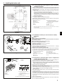
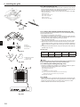
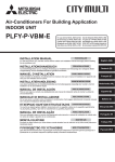
2.1. Check the indoor unit accessories (Fig. 2-1)
1
The indoor unit should be supplied with the following accessories.
Accessory name
2
4
3
5
6
8
Fig. 2-1
2
7
Q’ty
1
Installation template
1
2
Washers (with insulation)
Washers (without insulation)
4
4
3
Pipe cover (for refrigerant piping joint)
small diameter (liquid)
large diameter (gas)
1
1
4
Band (large)
Band (small)
6
2
5
Screw with washer (M5 × 25) for mounting grille
4
6
Drain socket
1
7
Insulation
1
8
Wireless junction cable
1
2. Installing the indoor unit
(mm)
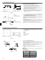
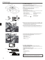
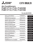
2.2. Ceiling openings and suspension bolt installation
locations (Fig. 2-2)
• Using the installation template (top of the package) and the gauge (supplied as an
accessory with the grille), make an opening in the ceiling so that the main unit can
be installed as shown in the diagram. (The method for using the template and the
gauge are shown.)
* Before using, check the dimensions of template and gauge, because they
change due to fluctuations of temperature and humidity.
* The dimensions of ceiling opening can be regulated within the range shown in
following diagram; so center the main unit against the opening of ceiling, ensuring that the respective opposite sides on all sides of the clearance between
them becomes identical.
• Use M10 (3/8”) suspension bolts.
* Suspension bolts are to be procured at the field.
• Install securely, ensuring that there is no clearance between the ceiling panel &
grille, and between the main unit & grille.
A
B
C
D
E
F
Outer side of main unit
Bolt pitch
Ceiling opening
Outer side of Grille
Grille
Ceiling
G Min. 500 mm (Entire periphery)
If setting the maintenance space for G, be
sure to leave is a minimum of 700 mm.
H
I
J
K
Maintenance space
Fresh air intake
Angle
Electric component box
* Note that the space between ceiling panel of the unit and ceiling slab and etc. must be 10
to 15 mm to be left.
* Leave the maintenance space at the electric component box end.
30°
C
120°
00
ø1
ø7
20
°
92
00
27
+5
0
0°
12
70
120
120°
15
5
ø1
(mm)
25
208
A
GB
Fig. 2-2
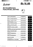
2.3. Installation of duct (in case of fresh air intake)
(Fig. 2-3)
Caution:
Linkage of duct fan and air conditioner
ln case that a duct fan is used, be sure to make it linked with the air conditioner
when outside air is taken.
Do not run the duct fan only. It can cause dew drop.
Making a duct flange (prepared locally)
• The shape of duct flange shown left is recommended.
Installation of duct flange
• Cut out the cutout hole. Do not knock it out.
• Install a duct flange to the cutout hole of the indoor unit with three 4 × 10 tapping
screws which should be prepared locally.
Installation of duct (should be prepared locally)
• Prepare a duct of which inner diameter fits into the outer diameter of the duct flange.
• In case that the environment above the ceiling is high temperature and high humidity,
wrap the duct in a heat insulate to avoid causing dew drop on the wall.
A Duct flange recommended shape
Fig. 2-3
B
C
D
E
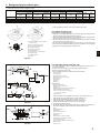
A Unit
B Grille
C Pillow
2
1
D
E
F
G
Ceiling
Rafter
Beam
Roof beam
H Use inserts rated at 100-150 kg
each (procure locally)
I Suspension bolts M10 (3/8”) (procure
locally)
J Steel reinforcing rod
*B: Suspension bolt pitch (see Fig. 2-2 B for details)
Fig. 2-4
(Thickness: 0.8 or more)
3-ø5 hole
Detail drawing of fresh air intake
Indoor unit
Ceiling surface
F
G
H
I
J
3-ø2.8 Burring hole
ø73.4 cutout hole
Duct flange (Prepared locally)
4 × 10 Tapping screw (Prepared locally)
Duct
2.4. Suspension structure (Give site of suspension
strong structure) (Fig. 2-4)
• The ceiling work differs according to the construction of the building. Building constructors and interior decorators should be consulted for details.
(1) Extent of ceiling removal: The ceiling must be kept completely horizontal and the
ceiling foundation (framework: wooden slats and slat holders) must be reinforced
in order to protect the ceiling from vibration.
(2) Cut and remove the ceiling foundation.
(3) Reinforce the ends of the ceiling foundation where it has been cut and add ceiling
foundation for securing the ends of the ceiling board.
(4) When installing the unit on a slanting ceiling, interlock a pillow between the ceiling
and the grille and set so that the unit is installed horizontally.
1 Wooden structures
• Use tie beams (single storied houses) or second floor beams (two story houses)
as reinforcing members.
• Wooden beams for suspending air conditioners must be sturdy and their sides must
be at least 6 cm long if the beams are separated by not more than 90 cm and their
sides must be at least 9 cm long if the beams are separated by as much as 180
cm. The size of the suspension bolts should be ø10 (3/8”). (The bolts do not come
with the unit.)
2 Ferro-concrete structures
Secure the suspension bolts using the method shown, or use steel or wooden hangers, etc. to install the suspension bolts.
3
2. Installing the indoor unit
2.5. Unit suspension procedures (Fig. 2-5)
27 +50
93
Min.30
A
B
C
D
E Mounting plate
F Washer (without insulation) (Accessory)
G Check using the Installation gauge
Suspension bolt (Procure locally)
Ceiling
Nut (Procure locally)
Washer (with insulation) (Accessory)
Suspend the main unit as shown in the diagram.
1. In advance, set the parts onto the suspension bolts in the order of the washers
(with insulation), washers (without insulation) and nuts (double).
• Fit the washer with cushion so that the insulation faces downward.
• In case of using upper washers to suspend the main unit, the lower washers
(with insulation) and nuts (double) are to be set later.
2. Lift the unit to the proper height of the suspension bolts to insert the mounting
plate between washers and then fasten it securely.
3. When the main unit can not be aligned against the mounting hole on the ceiling,
it is adjustable owing to a slot provided on the mounting plate. (Fig. 2-6)
• Make sure that step A is performed within 27-32 mm. Damage could result by
failing to adhere to this range.
Fig. 2-5
A
B
C
D
Main unit
Ceiling
Gauge (Grille accessory)
Ceiling opening dimensions
A
B
C
D
Main unit
Ceiling
Installation template (Accessory)
Screw with washer (Accessory)
GB
Fig. 2-6
2.6. Confirming the position of main unit and tightening
the suspension bolts (Fig. 2-7)
• Using the gauge attached to the grille, ensure that the bottom of the main unit is
properly aligned with the opening of the ceiling. Be sure to confirm this, otherwise
condensation may form and drip due to air leakage etc.
• Confirm that the main unit is horizontally levelled, using a level or a vinyl tube filled
with water.
• After checking the position of the main unit, tighten the nuts of the suspension bolts
securely to fasten the main unit.
• The installation template can be used as a protective sheet to prevent dust from
entering the main unit when the grilles are left unattached for a while or when the
ceiling materials are to be lined after installation of the unit is finished.
* As for the details of fitting, refer to the instructions given on the Installation template.
Fig. 2-7
3. Refrigerant pipe and drain pipe
3.1. Refrigerant and drainage piping locations of indoor
unit (Fig. 3-1)
A
B
C
D
E
F
G
Drain pipe
Ceiling
Grille
Refrigerant pipe (liquid)
Refrigerant pipe (gas)
Water supply inlet
Main unit
As viewed from A
Fig. 3-1
3.2. Connecting pipes (Fig. 3-2)
• When commercially available copper pipes are used, wrap liquid and gas pipes
with commercially available insulation materials (heat-resistant to 100°C or more,
thickness of 12 mm or more).
• The indoor parts of the drain pipe should be wrapped with polyethylene foam insulation materials (specific gravity of 0.03, thickness of 9 mm or more).
• Apply thin layer of refrigerant oil to pipe and joint seating surface before tightening
flare nut.
• Use two wrenches to tighten piping connections.
• Use refrigerant piping insulation provided to insulate indoor unit connections. Insulate
carefully.
øA
.4
R0
90° ±0.5°
45° ±2°
-R
8
0.
Warning:
When installing the unit, securely connect the refrigerant pipes before starting the compressor.
A Flare cutting dimensions
Fig. 3-2
4
Copper pipe O.D.
(mm)
Flare dimensions
øA dimensions (mm)
ø6.35
8.7 - 9.1
ø9.52
12.8 - 13.2
ø12.7
16.2 - 16.6
ø15.88
19.3 - 19.7
ø19.05
22.9 - 23.3
3. Refrigerant pipe and drain pipe
B Refrigerant pipe sizes & Flare nut tightening torque
P15/20/25/32/40
P50
P63/80
P100/125
R407C or R22
Liquid pipe
Gas pipe
Tightening
Tightening
Pipe size
Pipe size
torque
torque
(mm)
(mm)
(N·m)
(N·m)
ODø6.35 (1/4”)
14 - 18
ODø12.7 (1/2”)
49 - 61
ODø9.52 (3/8”)
14 - 18*
ODø15.88 (5/8”)
49 - 61*
ODø9.52 (3/8”)
34 - 42
ODø15.88 (5/8”)
68 - 82
ODø9.52 (3/8”)
34 - 42
ODø19.05 (3/4”)
68 - 82*
R410A
Liquid pipe
Gas pipe
Tightening
Tightening
Pipe size
Pipe size
torque
torque
(mm)
(mm)
(N·m)
(N·m)
ODø6.35 (1/4”)
14 - 18
ODø12.7 (1/2”)
49 - 61
ODø6.35 (1/4”)
14 - 18
ODø12.7 (1/2”)
49 - 61
ODø9.52 (3/8”)
34 - 42
ODø15.88 (5/8”)
68 - 82
ODø9.52 (3/8”)
34 - 42
ODø15.88 (5/8”)
68 - 82
Flare nut O.D.
Liquid
pipe
(mm)
17
17
22
22
Gas
pipe
(mm)
26
26
29
29
* Connect the joint with the following pipes: Liquid and gas pipes of P50, gas pipes of P100/P125.
C Apply refrigerating machine oil over the entire flare seat surface.
3.3. Indoor unit (Fig. 3-3)
A Refrigerant pipe and insulating material
(Procure locally)
Pipe cover (large) (Accessory)
Pipe cover (small) (Accessory)
Refrigerant pipe (gas)
Refrigerant pipe (liquid)
Band (Accessory)
Cross-sectional view of connection
Refrigerant pipe
Insulating material
Squeeze
GB
B
C
D
E
F
G
H
I
J
Heat insulation for refrigerant pipes:
1 Wrap the enclosed large-sized pipe cover around the gas pipe, making sure that
the end of the pipe cover touches the side of the unit.
2 Wrap the enclosed small-sized pipe cover around the liquid pipe, making sure that
the end of the pipe cover touches the side of the unit.
3 Secure both ends of each pipe cover with the enclosed bands. (Attach the bands
20 mm from the ends of the pipe cover.)
• After connecting the refrigerant piping to the indoor unit, be sure to test the pipe
connections for gas leakage with nitrogen gas. (Check that there is no refrigerant
leakage from the refrigerant piping to the indoor unit.)
Fig. 3-3
1
3.4. Drainage piping work (Fig. 3-4)
Max. 20m
• Use VP25 (O.D. ø32 (1-1/4”) PVC TUBE) for drain piping and provide 1/100 or
more downward slope.
• Be sure to connect the piping joints using a polyvinyl type adhesive.
• Observe the figure for piping work.
• Use the included drain hose to change the extraction direction.
1 Correct piping
2 Wrong piping
A Insulation (9 mm or more)
B Downward slope (1/100 or more)
C Support metal
K Air bleeder
L Raised
M Odor trap
Grouped piping
D O.D. ø32 PVC TUBE
E Make it as large as possible
F Indoor unit
G Make the piping size large for grouped piping.
H Downward slope (1/100 or more)
I O.D. ø38 PVC TUBE for grouped piping.
1.5~2m
Max. 15cm
2
(9 mm or more insulation)
J Up to 500 mm
Fig. 3-4
(mm)
30
30
30
Fig. 3-5
1. Connect the drain socket (supplied with the unit) to the drain port. (Fig. 3-5)
(Affix the tube using PVC adhesive then secure it with a band.)
2. Install a locally purchased drain pipe (PVC pipe, O.D. ø32).
(Affix the pipe using PVC adhesive then secure it with a band.)
3. Insulate the tube and pipe. (PVC pipe, O.D. ø32 and socket)
4. Check that drain flows smoothly.
5. Insulate the drain port with insulating material, then secure the material with a
band. (Both insulating material and band are supplied with the unit.)
A Unit
B Insulating material
C Band (large)
D Drain port (transparent)
E Insertion margin
F Matching
G Drain pipe (O.D. ø32 PVC TUBE)
H Insulating material (purchased locally)
I Transparent PVC pipe
J O.D. ø32 PVC TUBE (Slope 1/100 or more)
K Band (small)
L Drain socket
5
4. Electrical work
4.1. Indoor unit (Fig. 4-1)
1.Remove 2 screws to detach the electric component cover.
2.Route each cable through the wiring intake into the electric component box. (Procure
power supply cable and control cable locally.)
3.Securely connect the power supply cable and control cable to the terminal
blocks.
4.Secure the cables with clamps outside the electric component box.
5.Attach the electric component cover as it was.
• Do not allow slackening of the terminal screws.
• Always install earth.
(Earth cable dia: Thicker than 1.6 mm)
• Fix power supply cable and control cable to electric component box by using buffer
bushing for tensile force. (PG connection or the like.)
A
B
C
D
Electric component cover
Electric component box
Entry for power supply cable
Entry for remote control cable and transmission cable
E Cable clamp
F Power supply terminals (L, N,
)
G
H
I
J
K
L
M
Transmission terminals (M1, M2, S)
MA Remote controller terminal (1. 2)
Indoor controller
Power board
Remote control cable
Transmission cable
Power supply cable
55 mm
12 mm
Fig. 4-1
GB
■ When using the panel with wireless signal receiver “SLP-2ALW”, install
wireless junction cable for connecting with the cable from the panel through
the following steps before installing the main unit.
(1) Take out the wireless junction cable that is supplied with the accessories.
(2) Route the indoor controller board connector (white) of the wireless junction cable
through the main unit BUSH in the direction indicated by the arrow. (Fig. 4-2)
Fig. 4-2
(3) Route the wireless junction cable through the electric component box BUSH, and
then connect the cable to CN90 of the indoor controller board. (Fig. 4-3)
(4) Secure the cables and wires with the clamp.
A Wireless junction cable (Accessory)
B Main unit BUSH
C Electric component box
D Electric component box BUSH
E Clamp
F Indoor controller board
4.2. Power supply wiring
Fig. 4-3
~220-240V
A
D
B
C
A
B
C
C
C
C
A Ground-fault interrupter
B Local switch/Wiring breaker
C Indoor unit
D Pull box
D
~220-240V
C
LN
TB2
Fig. 4-4
6
• Wiring size must comply with the applicable local and national codes.
• Power supply cable of appliance shall not be lighter than design 245 IEC 53 or 227
IEC57, 245 IEC 53 or 227 IEC 53.
• Install an earth line longer than other cables.
• A switch with at least 3 mm, 1/8 inch contact separation in each pole shall be
provided by the air conditioner installation.
[Fig.4-4]
M1 M2 S
TB5
1 2
TB15
Warning:
Never splice the power cable or the indoor-outdoor connection cable,
otherwise it may result in a smoke, a fire or communication failure.
4. Electrical work
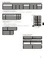
Total operating current of the indoor
unit
Minimum wire thickness (mm²)
Ground-fault interrupter *1
Breaker for wiring
(NFB)
Local switch (A)
Main cable
Branch
Ground
Capacity
Fuse
F0 = 16A or less *2
1.5
1.5
1.5
20 A current sensitivity *3
16
16
20
F0 = 25A or less *2
2.5
2.5
2.5
30 A current sensitivity *3
25
25
30
F0 = 32A or less *2
4.0
4.0
4.0
40 A current sensitivity *3
32
32
40
Apply to IEC61000-3-3 about max. permissive system impedance.
*1 The Ground-fault interrupter should support inverter circuit.
The Ground-fault interrupter should combine using of local switch or wiring breaker.
*2 Please take the larger of F1 or F2 as the value for F0.
F1 = Total operating maximum current of the indoor units × 1.2
F2 = {V1 × (Quantity of Type1)/C} + {V1 × (Quantity of Type2)/C} + {V1 × (Quantity of Type3)/C} + {V1 × (Quantity of Others)/C}
Type 2
PEFY-VMA
Type 3
PEFY-VMHS
Others
Other indoor unit
V1
V2
18.6
2.4
38
1.6
13.8
4.8
0
0
Sample chart
6000
600
C : Multiple of tripping current at tripping time 0.01s
Please pick up "C" from the tripping characteristic of the breaker.
<Example of "F2" calculation>
*Condition PEFY-VMS × 4 + PEFY-VMA × 1, C = 8 (refer to right sample chart)
F2 = 18.6 × 4/8 + 38 × 1/8
= 14.05
→ 16A breaker (Tripping current = 8 × 16A at 0.01s)
Current sensitivity
30 or less
30 mA 0.1sec or less
100 or less
100 mA 0.1sec or less
Wire thickness
10
1
0.01
1
2
3
4
6
8 10
20
C
Rated Tripping current (x)
V3
2
1.5 mm
48
2.5 mm2
56
2
66
4.0 mm
60
0.1
*3 Current sensitivity is calculated using the following formula.
G1 = V2 × (Quantity of Type1) + V2 × (Quantity of Type2) + V2 × (Quantity of Type3) + V2 × (Quantity of Others)
+ V3 × (Wire length[km])
G1
SAMPLE
GB
PLFY-VBM, PMFY-VBM, PEFY-VMS,
PCFY-VKM, PKFY-VHM, PKFY-VKM
Tripping Time [s]
Indoor unit
Type 1
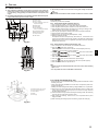
4.3. Types of control cables
1. Wiring transmission cables
Types of transmission cable
Shielding wire CVVS or CPEVS
Cable diameter
More than 1.25 mm2
Length
Less than 200 m
2. M-NET Remote control cables
Types of remote control cable
Shielding wire MVVS
Cable diameter
More than 0.5 to 1.25 mm2
Length
Add any portion in excess of 10 m to within
the longest allowable transmission cable
length 200 m.
3. MA Remote control cables
Types of remote control cable
2-core cable (unshielded)
Cable diameter
0.3 to 1.25 mm2
Length
Less than 200 m
7
4. Electrical work
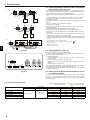
4.4. Connecting remote controller, indoor and outdoor
transmission cables (Fig. 4-5)
1
• Connect indoor unit TB5 and outdoor unit TB3. (Non-polarized 2-wire) The “S” on
indoor unit TB5 is a shielding wire connection. For specifications about the connecting cables, refer to the outdoor unit installation manual.
• Install a remote controller following the manual supplied with the remote controller.
• Connect the remote controller’s transmission cable within 10 m using a 0.75 mm2
core cable. If the distance is more than 10 m, use a 1.25 mm2 junction cable.
1 MA Remote controller
• Connect the “1” and “2” on indoor unit TB15 to a MA remote controller. (Non-polarized
2-wire)
• DC 9 to 13 V between 1 and 2 (MA remote controller)
2 M-NET Remote controller
• Connect the “M1” and “M2” on indoor unit TB5 to a M-NET remote controller.
(Nonpolarized 2-wire)
• DC 24 to 30 V between M1 and M2 (M-NET remote controller)
3 Wireless remote controller (When installing wireless signal receiver)
• Connect the wire of wireless signal receiver (9-pole cable) to CN90 of indoor controller board.
• When more than two units are run under group control using wireless remote
controller, connect TB15 each with the same number.
• To change Pair No. setting, refer to installation manual attached to wireless remote
controller. (In the default setting of indoor unit and wireless remote controller, Pair
No. is 0.)
A Terminal block for indoor transmission cable
B Terminal block for outdoor transmission cable (M1(A), M2(B), (S))
C Remote controller
D Wireless signal receiver
E Wireless remote controller
2
GB
3
Fig. 4-5
4.5. Setting addresses (Fig. 4-6)
(Be sure to operate with the main power turned OFF.)
• There are two types of rotary switch setting available: setting addresses 1 to 9 and
over 10, and setting branch numbers.
1 How to set addresses
Example: If Address is “3”, remain SW12 (for over 10) at “0”, and match SW11
(for 1 to 9) with “3”.
2 How to set branch numbers SW14 (Series R2 only)
Match the indoor unit’s refrigerant pipe with the BC controller’s end connection
number.
Remain other than series R2 at “0”.
• The rotary switches are all set to “0” when shipped from the factory. These switches
can be used to set unit addresses and branch numbers at will.
• The determination of indoor unit addresses varies with the system at site. Set them
referring to the Data Book.
Fig. 4-6
4.6. Sensing room temperature with the built-in sensor
in a remote controller
If you want to sense room temperature with the built-in sensor in a remote controller,
set SW1-1 on the control board to “ON”. The setting of SW1-7 and SW1-8 as
necessary also makes it possible to adjust the air flow at a time when the heating
thermometer is OFF.
4.7. Electrical characteristics
Model
Symbols: MCA: Max. Circuit Amps (= 1.25×FLA)
FLA: Full Load Amps
IFM: Indoor Fan Motor
Output: Fan motor rated output
Power supply
Output (kW)
FLA (A)
PLFY-P15VCM-E
0.24
0.008
0.19
PLFY-P20VCM-E
0.29
0.011
0.23
0.29
0.015
0.23
0.35
0.020
0.28
0.35
0.020
0.28
PLFY-P32VCM-E
PLFY-P40VCM-E
8
220-240V / 50Hz
Range +- 10%
IFM
MCA (A)
PLFY-P25VCM-E
Volts/ Hz
Max.: 264V
Min.: 198V
5. Installing the grille
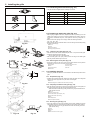
5.1. Check the grille accessories (Fig. 5-1)
1
• The grille should be supplied with the following accessories.
Accessory name
3
2
4
5
Q’ty
Remark
1
Grille
1
650 × 650 (mm)
2
Screw with washer
4
M5 × 0.8 × 25 (mm)
3
Gauge
1
4
Fastener
2
5
Band
2
Fig. 5-1
• With the gauge supplied with this kit, adjust and check the positioning of the unit
relative to the ceiling. If the unit is not properly positioned in the ceiling, there may
be air leaks, condensation may form, or the up/down vanes may not operate correctly.
• Make sure that the opening in the ceiling is within the following tolerances:
576 × 576 - 620 × 620
• Make sure that step A is performed within 27-32 mm. Damage could result by failing
to adhere to this range.
A Main unit
B Ceiling
C Gauge (Accessory)
D Ceiling opening dimensions
Fig. 5-2
5.2.1. Removing the intake grille (Fig. 5-3)
• Slide the levers in the direction indicated by the arrow 1 to open the intake grille.
• Unlatch the hook that secures the grille.
* Do not unlatch the hook for the intake grille.
• With the intake grille in the “open” position, remove the hinge of the intake grille
from the grille as indicated by the arrow 2.
Fig. 5-3
5.2.2. Removing the corner panel (Fig. 5-4)
• Remove the screw from the corner of the corner panel. Slide the corner panel as
indicated by the arrow 1 to remove the corner panel.
E Hole for the grille’s hook
A Intake grille
F Corner panel
B Grille
G Screw
C Intake grille levers
D Grille hook
Fig. 5-4
15~20
(mm)
5.3. Installing the grille
• Please pay attention because there is a restriction in the attachment position of the
grille.
5.3.1. Preparations (Fig. 5-5)
• Install the two enclosed screws with washer in the main unit (at the corner refrigerant
pipe area and at the opposite corner) as shown in the diagram.
A Main unit
B Detailed diagram of installed screw with washer (accessory).
Fig. 5-5
5.3.2. Temporary installation of the grille (Fig. 5-6)
• Align the electric component box of the main unit and the receiver of the grille, and
then temporarily secure the grille using the bell shaped holes.
* Make sure that the lead wiring of the grille does not get pinched between the
grille and the main unit.
A Main unit
B Electric component box
C Screw with washer (for temporary use)
D Screw with washer (Accessory)
E Grille
F Bell shaped hole
G Receiver (for SLP-2ALW)
5.3.3. Securing the grille (Fig. 5-7)
• Secure the grille to the main unit by tightening the previously installed two screws
(with captive washer) as well as the two remaining screws (with captive washer).
* Make sure that there are no gaps between the main unit and the grille or the
grille and the ceiling.
A Ceiling
B Main unit
C Grille
D Make sure that there are no gaps.
Fig. 5-6
Fig. 5-7
9
GB
5.2. Preparing to attach the grille (Fig. 5-2)
5. Installing the grille
5.3.4. Wire connection (Fig. 5-8)
• Be sure to connect the unit to the connector (white: 10-pole/red: 9-pole). Next, attach the white glass tube that comes with the main unit so that the tube covers the
connector. Close the opening of the glass tube with the band.
• Make sure that there is no slack in the each lead wire at the fastener on the grille.
A Fastener (Accessory)
B White glass tube
C Connector of the main unit
D Connector of the grille
E Band (Accessory)
F Receiver (for SLP-2ALW)
Fig. 5-8
GB
5.4. Locking the up/down airflow direction (Fig. 5-9)
A
B
C
D
Button
Vane motor
Up/down vanes
Connector
Specified range
Fig. 5-9
Up/down airflow
direction
Horizontal 30°
Downward 45°
Downward 55°
Downward 70°
A (mm)
21
25
28
30
E Measurement standard
• The vanes can be set between 21 and 30 mm.
F Up/down vanes
Caution:
Do not set the up/down vanes passed the specified range. Condensation could
form on and drop from the ceiling, or the unit could malfunction.
position of grille
Fig. 5-10
The vanes of the unit can be set and locked in up or down orientations depending
upon the environment of use.
• Set according to the preference of the customer.
The operation of the fixed up/down vanes and all automatic controls cannot be
performed using the remote controller. In addition, the actual position of the vanes
may differ from the position indicated on the remote controller.
1 Turn off the main power switch.
Injuries and or an electrical shock may occur while the fan of the unit is rotating.
2 Disconnect the connector for the vane motor of the vent that you want to lock.
(While pressing the button, remove the connector in the direction indicated by
the arrow as shown in the diagram.) After removing the connector, insulate it with
tape.
3 To adjust the desired airflow direction, slowly move the up/down vanes within the
specified range. (Fig.5-10)
5.5. Installing the intake grille (Fig. 5-11)
• Perform the procedure that is described in “5.2. Preparing to attach the grille” in
reverse order to install the intake grille and the corner panel.
A Refrigerant piping of the main unit
B Drain piping of the main unit
C Corner panel
* Installation in any position is possible.
D Position of the levers on the intake grille when sent from the factory.
* Although the clips can be installed in any of four positions.
E Receiver (for SLP-2ALW)
5.6. Check
• Make sure that there is no gap between the unit and the grille, or between the grille
and the surface of the ceiling. If there is any gap between the unit and the grille, or
between the grille and the surface of the ceiling, it may cause dew to collect.
• Make sure that the wires have been securely connected.
SLP-2ALW
Fig. 5-11
10
6. Test run
6.1. Before test run
► After completing installation and the wiring and piping of the indoor and
outdoor units, check for refrigerant leakage, looseness in the power supply
or control wiring, wrong polarity, and no disconnection of one phase in the
supply.
► Use a 500-volt megohmmeter to check that the resistance between the power
supply terminals and ground is at least 1.0 MΩ.
A ON/OFF button
B Test run display
C Indoor temperature liquid line
temperature display
°C
°C
SIMPLE
TEMP.
MENU
BACK
PAR-21MAA
MONITOR/SET
D ON/OFF lamp
E Power display
F Error code display
ON/OFF
ON/OFF
DAY
CLOCK
G
H
I
M
FILTER
CHECK TEST
OPERATION
CLEAR
Test run remaining time display
Set temperature button
Mode selection button
Fan speed button
TEST button
Fig. 6-1
6.2. Test run
The following 3 methods are available.
6.2.1. Using wired remote controller (Fig. 6-1)
1 Turn on the power at least 12 hours before the test run.
2 Press the [TEST] button twice. ➡ “TEST RUN” liquid crystal display
3 Press the [Mode selection] button. ➡ Make sure that wind is blown out.
4 Press the [Mode selection] button and switch to the cooling (or heating) mode.
5
6
7
8
➡ Make sure that cold (or warm) wind is blown out.
Press the [Fan speed] button. ➡ Make sure that the wind speed is switched.
Check operation of the outdoor unit fan.
Release test run by pressing the [ON/OFF] button. ➡ Stop
Register a telephone number.
The telephone number of the repair shop, sales office, etc., to contact if an error
occurs can be registered in the remote controller. The telephone number will be
displayed when an error occurs. For registration procedures, refer to the operation
manual for the indoor unit.
6.2.2. Using wireless remote controller (Fig. 6-2)
1 Turn on the power to the unit at least 12 hours before the test run.
2 Press the
button twice continuously.
(Start this operation from the status of remote controller display turned off.)
A
and current operation mode are displayed.
3 Press the
mode, then check whether
4 Press the
mode, then check whether
button to activate
cool air is blown out from the unit.
button to activate
warm air is blown out from the unit.
5 Press the
button and check whether fan speed changes.
6 Press the
button and check whether the auto vane operates properly.
7 Press the ON/OFF button to stop the test run.
Note:
• Point the remote controller towards the indoor unit receiver while following
steps 2 to 7.
• It is not possible to run the in FAN, DRY or AUTO mode.
Fig. 6-2
6.3. Check of drainage (Fig. 6-3)
A
B
C
D
E
Insert the pump end 3 to 5 cm
Cover of water supply inlet
About 1000 cc
Water
Drain plug
• During the trial run, ensure the water is being properly drained out and that no water
is leaking from joints.
• Always check this during installation even if the unit is not required to provide cooling/drying at that time.
• Similarly, check the drainage before finishing ceiling installation in a new premises.
(1) Remove the cover of the water supply inlet and add about 1000 cc of water using
a water supply pump etc. During this process, be careful not to spray water into
the drain pump mechanism.
(2) Confirm that water is being drained out through the drainage outlet, after switching
over from remote control mode to trial run mode.
(3) After checking the drainage, ensure that the cover is replaced and the power
supply is isolated.
(4) After confirming the drainage system is functioning, replace the drain plug.
Fig. 6-3
11
GB
TEST RUN
COOL, HEAT
► Do not carry out this test on the control wiring (low voltage circuit) terminals.
Warning:
Do not use the air conditioner if the insulation resistance is less than 1.0 MΩ.
This product is designed and intended for use in the residential,
commercial and light-industrial environment.
The product at hand is
based on the following
EU regulations:
•
•
•
•
Low Voltage Directive 2006/95
Electromagnetic Compatibility Directive
2004/108 EEC
Machinery Directive 2006/42/EC
Energy-related Products Directive
2009/125/EC
Please be sure to put the contact address/telephone number on
this manual before handing it to the customer.
HEAD OFFICE: TOKYO BLDG., 2-7-3, MARUNOUCHI, CHIYODA-KU, TOKYO 100-8310, JAPAN
Authorized representative in EU: MITSUBISHI EUROPE, B.V. HARMAN HOUSE,
1 GEORGE STREET, UXBRIDE,
MIDDLE SEX UB8 1QQ.U.K.
RG79D646K04
Printed in Thailand