1
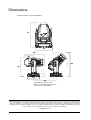
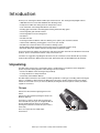
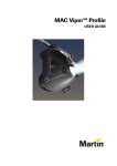
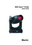
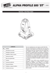
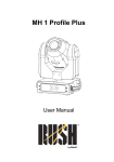
MAC Viper Performance™
SAFETY AND INSTALLATION MANUAL
Dimensions
All measurements are given in millimeters
731
472
566
255
748
551
335
650
This minimum center-to-center
distance can be reduced if pan limits
are set via the control menus
© 2012-2013 Martin Professional A/S. Information subject to change without notice. Martin Professional A/S and all affiliated companies disclaim liability for any injury, damage, direct or indirect loss, consequential or economic loss or any other loss occasioned by
the use of, inability to use or reliance on the information contained in this document. The Martin logo, the Martin name and all other
trademarks in this document pertaining to services or products by Martin Professional A/S or its affiliates and subsidiaries are trademarks owned or licensed by Martin Professional A/S or its affiliates or subsidiaries.
P/N 35000274, Rev. B
Contents
Safety Information . . . . . . . . . . . . . . . . . . . . . . . . . . . . . . . . . . . . . . . . . . . . . . . . . . . . . . . . . . . . . . . . . . 4
Introduction . . . . . . . . . . . . . . . . . . . . . . . . . . . . . . . . . . . . . . . . . . . . . . . . . . . . . . . . . . . . . . . . . . . . . . . . 6
Unpacking . . . . . . . . . . . . . . . . . . . . . . . . . . . . . . . . . . . . . . . . . . . . . . . . . . . . . . . . . . . . . . . . . . . . . . . . 6
Packing . . . . . . . . . . . . . . . . . . . . . . . . . . . . . . . . . . . . . . . . . . . . . . . . . . . . . . . . . . . . . . . . . . . . . . . . . . 7
Physical installation . . . . . . . . . . . . . . . . . . . . . . . . . . . . . . . . . . . . . . . . . . . . . . . . . . . . . . . . . . . . . . . . 8
AC power . . . . . . . . . . . . . . . . . . . . . . . . . . . . . . . . . . . . . . . . . . . . . . . . . . . . . . . . . . . . . . . . . . . . . . . . . 11
Power input . . . . . . . . . . . . . . . . . . . . . . . . . . . . . . . . . . . . . . . . . . . . . . . . . . . . . . . . . . . . . . . . . . . . . . 11
DMX data link . . . . . . . . . . . . . . . . . . . . . . . . . . . . . . . . . . . . . . . . . . . . . . . . . . . . . . . . . . . . . . . . . . . . . 13
Service and maintenance . . . . . . . . . . . . . . . . . . . . . . . . . . . . . . . . . . . . . . . . . . . . . . . . . . . . . . . . . . 14
Tilt lock. . . . . . . . . . . . . . . . . . . . . . . . . . . . . . . . . . . . . . . . . . . . . . . . . . . . . . . . . . . . . . . . . . . . . . . . . .
Lamp . . . . . . . . . . . . . . . . . . . . . . . . . . . . . . . . . . . . . . . . . . . . . . . . . . . . . . . . . . . . . . . . . . . . . . . . . . .
Access to the head . . . . . . . . . . . . . . . . . . . . . . . . . . . . . . . . . . . . . . . . . . . . . . . . . . . . . . . . . . . . . . . .
Access to the framing module . . . . . . . . . . . . . . . . . . . . . . . . . . . . . . . . . . . . . . . . . . . . . . . . . . . . . . . .
Cleaning. . . . . . . . . . . . . . . . . . . . . . . . . . . . . . . . . . . . . . . . . . . . . . . . . . . . . . . . . . . . . . . . . . . . . . . . .
Replacing the head air filters . . . . . . . . . . . . . . . . . . . . . . . . . . . . . . . . . . . . . . . . . . . . . . . . . . . . . . . . .
Lubrication . . . . . . . . . . . . . . . . . . . . . . . . . . . . . . . . . . . . . . . . . . . . . . . . . . . . . . . . . . . . . . . . . . . . . . .
Replacing optical components. . . . . . . . . . . . . . . . . . . . . . . . . . . . . . . . . . . . . . . . . . . . . . . . . . . . . . . .
14
14
17
18
19
19
21
21
Using the fixture . . . . . . . . . . . . . . . . . . . . . . . . . . . . . . . . . . . . . . . . . . . . . . . . . . . . . . . . . . . . . . . . . . . 27
Applying power . . . . . . . . . . . . . . . . . . . . . . . . . . . . . . . . . . . . . . . . . . . . . . . . . . . . . . . . . . . . . . . . . . . 27
Troubleshooting . . . . . . . . . . . . . . . . . . . . . . . . . . . . . . . . . . . . . . . . . . . . . . . . . . . . . . . . . . . . . . . . . . 28
Specifications . . . . . . . . . . . . . . . . . . . . . . . . . . . . . . . . . . . . . . . . . . . . . . . . . . . . . . . . . . . . . . . . . . . . . 29
Safety Information
WARNING!
Read the safety precautions in this section before
installing, powering, operating or servicing this
product.
The following symbols are used to identify important safety information on the product and in this document:
DANGER!
DANGER!
DANGER!
Safety hazard.
Refer to
Hazardous
Risk of severe manual before voltage. Risk of
injury or death.
installing,
severe or lethal
powering or
electric shock.
servicing.
Warning!
Fire hazard.
Warning!
Burn hazard.
Hot surface. Do
not touch.
Warning!
Risk of eye
injury. Safety
glasses must
be worn.
Warning!
Risk of hand
injury. Safety
gloves must be
worn.
Warning! The MAC Viper Performance™ contains components that are accessible and live at high
voltage while the fixture is connected to power and that remain under tension for 30 minutes after
power is disconnected. Only technicians who are authorized by Martin™ and who have access to
the Martin™ service documentation for the MAC Viper Performance are permitted to open the base
and yoke of the fixture. The user may open the MAC Viper Performance’s head only to carry out the
service operations described in this manual, following the warnings and instructions provided.
Warning! Risk Group 3 (high risk) product according to EN 62471. Do not view the light output with
optical instruments or any device that may concentrate the beam.
The latest versions of this Safety and Installation Manual and the MAC Viper Performance User Guide are
available for download from the MAC Viper Performance Product Support page on the Martin™ website at
www.martin.com. Before you install, operate or service the MAC Viper Performance, check the Martin™
website and make sure that you have the latest user documentation for the fixture. Document revisions are
indicated at the bottom of page 2. Follow the safety precautions and observe all warnings in this manual, in
the MAC Viper Performance User Guide, and printed on the fixture.
This product is for professional use only. It is not for household use.
This product presents risks of severe injury or death due to fire and burn hazards, electric shock, lamp
explosion and falls.
Refer any service operation not described in this manual or in the MAC Viper Performance User Guide to
Martin™ Service or an authorized Martin™ Service partner.
If you have questions about how to operate the fixture safely, please contact your Martin™ supplier or call
the Martin™ 24-hour service hotline on +45 8740 0000, or in the USA on 1-888-tech-180.
PROTECTION FROM ELECTRIC SHOCK
• Do not remove any cover from the fixture’s base or yoke.
• Disconnect the fixture from AC power before removing or installing any cover or part – including the
lamp – from the head and when not in use.
• Ensure that the fixture is electrically connected to ground (earth).
• Use only a source of AC power that complies with local building and electrical codes and has both
overload and ground-fault (earth-fault) protection.
• The power input cable must be rated 20 A, hard usage type and heat-resistant to 90° C (194° F)
minimum. It must have three conductors and an outer cable diameter of 5 - 15 mm (0.2 - 0.6 in.). In North
America the cable must be 12 AWG minimum conductor size, SJT or better. In the EU the cable must be
2.5 mm², HAR compliant.
• Before using the fixture, check that all power distribution equipment and cables are in perfect condition
and rated for the current requirements of all connected devices.
• Isolate the fixture from power immediately if the power cable or power plug are in any way damaged,
defective or wet, or if they show signs of overheating.
• Do not expose the fixture to rain or moisture.
LAMP SAFETY
• Prolonged exposure to an unshielded discharge lamp can cause eye and skin burns. Do not stare directly
into the light output. Never look at an exposed lamp while it is lit. Do not operate the fixture with missing or
damaged covers, shields, lenses or ultraviolet screens.
• A hot discharge lamp is under pressure and can explode without warning. Allow the fixture to cool for at
least 30 minutes and protect yourself with safety glasses and gloves before handling a lamp or servicing
the fixture internals.
• Replace the lamp immediately if it becomes visually deformed, damaged or in any way defective
• Monitor hours of lamp use and lamp intensity and replace the lamp when it reaches the limit of its service
life as specified in this product’s specifications or by the lamp manufacturer.
• Install only a lamp that is specifically approved by Martin™ for this product.
• If the quartz envelope of a discharge lamp is broken, the lamp releases a small quantity of mercury and
other toxic gases. If a discharge lamp explodes in a confined area, evacuate the area and ventilate it
thoroughly. Wear nitrite gloves when handling a broken discharge lamp. Treat broken or used discharge
lamps as hazardous waste and send to a specialist for disposal.
PROTECTION FROM BURNS AND FIRE
• The exterior of the fixture becomes very hot – up to 150° C (302° F) – during use. Avoid contact by
persons and materials. Allow the fixture to cool for at least 30 minutes before handling.
• Keep all combustible materials (e.g. fabric, wood, paper) at least 0.3 m (12 in.) away from the fixture. Keep
flammable materials well away from the fixture.
• Provide a minimum clearance of 0.1 m (4 in.) around fans and air vents.
• Do not illuminate surfaces within 1.6 m (5.2 ft.) of the fixture.
• Position or shade the head so that the lens cannot face the sun – even for a few seconds – during daylight
hours. The lens can focus the sun's rays inside the fixture, creating a potential fire hazard.
• Do not operate the fixture if the ambient temperature (Ta) exceeds 40° C (104° F).
• Do not modify the fixture in any way not described in this manual or the product’s User Guide or install
other than genuine Martin™ parts. Do not stick filters, masks or other materials onto any lens or other
optical component. Use only accessories approved by Martin™ to mask or modify the light beam.
PROTECTION FROM INJURY
• Do not lift or carry the fixture alone.
• The handles in the base and on the top of the yoke are for use when carrying the product only. Do not use
them for hoisting, primary attachment or secondary attachment.
• Use two evenly spaced clamps to suspend the fixture from rigging structures. Do not use only one clamp.
• When clamping the fixture to a truss or other supporting structure at any other angle than with the yoke
hanging vertically downwards, use two half-coupler clamps. Do not use G-clamps, quick-trigger clamps or
any other type of clamp that does not completely encircle the supporting structure when fastened.
• When suspending the fixture, ensure that the supporting structure and all hardware used can hold at least
10 times the weight of all devices suspended from them.
• Install as described in this manual a secondary attachment such as a safety cable that is approved by an
official body such as TÜV as a safety attachment for the weight of all the fixtures it secures. The safety
cable must comply with EN 60598-2-17 Section 17.6.6 and also be capable of bearing a static suspended
load ten times the weight of the fixture.
• Check that all external covers and rigging hardware are securely fastened.
• Block access below the work area and work from a stable platform whenever installing, servicing or
moving the fixture.
Safety Information
5
Introduction
Thank you for selecting the Martin™ MAC Viper Performance™. This moving-head spotlight features:
• 1000 Watt short-arc Osram HTI 1000/PS Lok-it discharge lamp
• Full-spectrum CMY color mixing and color temperature control
• Color wheel with 7 interchangeable dichroic color filters
• Rotating gobo wheel with 5 interchangeable rotating texture/breakup gobos
• Interchangeable gobo animation wheel
• Interchangeable four-facet rotating prism
• Variable iris
• Variable frost filter
• Full-range mechanical dimmer with four dimming curve options, plus mechanical shutter
• 16-bit control of dimming, rotating gobos, zoom, focus, pan and tilt
• Variable focus and zoom with 3-zone zoom/focus linking system
• Backlit graphic display and battery power (mains power not required for fixture setup)
• Electronic “flicker-free” ballast and auto-sensing switch-mode power supply.
For the latest firmware updates, documentation, and other information about this and all Martin Professional
products, please visit the Martin website at http://www.martin.com
Comments or suggestions regarding this document may be e-mailed to [email protected] or posted to:
Technical Documentation, Martin Professional A/S, Olof Palmes Allé 18, DK-8200 Aarhus N, Denmark.
Unpacking
The MAC Viper Performance is packaged in either a cardboard box or a flightcase that is designed to
protect the product during shipment. The following items are included:
• Osram HTI 1000/PS Lok-it discharge lamp (installed)
• 2 omega brackets for clamp attachment
• This Safety and Installation Manual
The MAC Viper Performance User Guide, containing full details of setting up, controlling and monitoring the
fixture, is available for download from the MAC Viper Performance Product Support page on the Martin
website at www.martin.com. If you have any difficulty locating this document, please contact your Martin
supplier for assistance.
Tilt lock
Release the tilt lock before applying power to the
fixture.
Release the tilt lock before packing the fixture in its
Martin™ flightcase.
See Figure 1. Release the tilt lock by pushing the
lock in towards the yoke (you can reapply the tilt lock
by first checking that the power is off and then
pushing the lock back in towards the yoke from the
other side).
There is no pan lock on the MAC Viper
Performance.
6
Figure 1: Tilt lock
MAC Viper Performance Safety and Installation Guide
Packing
Important!
Release the tilt lock and allow the fixture to cool before packing it in its flightcase.
The anti-shock material in the MAC Viper Performance flightcase is designed to protect the head without the
tilt lock applied. Release the tilt lock when transporting the fixture in the flightcase. Leaving the tilt lock
applied may cause damage that is not covered by the product warranty.
Introduction
7
Physical installation
Warning! The MAC Viper Performance has a powerful pan motor. The torque reaction when the head
is panned suddenly can cause the base to move if the fixture is standing unsecured on a surface.
Do not apply power to the MAC Viper Performance unless the base is securely fastened to a surface
or to rigging hardware.
Warning! Use 2 clamps to rig the fixture. Do not hang the fixture from only one clamp. Lock each
clamp with both 1/4-turn fasteners. Fasteners are locked only when turned fully clockwise.
Warning! When suspending the fixture above ground level, secure it against failure of primary
attachments by attaching a safety wire that is approved as a safety attachment for the weight of the
fixture to the attachment point in the base. Do not use the carrying handles for secondary
attachment.
Warning! When clamping the fixture to a truss or other structure at any other angle than with the
yoke hanging vertically downwards, use two clamps of half-coupler type. Do not use any type of
clamp that does not completely encircle the structure when fastened.
Warning! Position or shade the head so that the lens does not face the sun at any time – even for a
few seconds – during daylight hours. The MAC Viper Performance’s lens can focus the sun's rays
inside the fixture, creating a potential fire hazard and causing internal damage.
Important! Do not point the output from other lighting fixtures at the MAC Viper Performance from a
distance of less than 3 m (10 ft.), as intense illumination can damage the display.
The MAC Viper
Performance can be
fastened to a surface
such as a stage or
clamped to a truss in any
orientation. Clamps must
be half-coupler type (see
Figure 3) unless the
fixture is installed with
the yoke hanging
vertically downwards, in
which case other clamp
types that are approved
for the supported weight
may be used.
The mounting points
allow the clamp brackets
to be fastened parallel,
perpendicular or at 45° to
the front, as shown in
Figure 2.
256
256
256
45°
Figure 2: Clamp bracket positions
8
MAC Viper Performance Safety and Installation Guide
45°
Clamping the fixture on a truss
1. Check that the rigging clamps are
undamaged and can bear at least
10 times the weight of the fixture.
Check that the structure can bear
at least 10 times the weight of all
installed fixtures, clamps, cables,
auxiliary equipment, etc.
2. Bolt each clamp securely to a
clamp attachment bracket with an
M12 bolt (minimum grade 8.8) and
lock nut.
Half-coupler
rigging clamp
Omega clamp
attachment bracket
Figure 3: Martin rigging hardware
3. See Figure 4. Note the position
of the arrow on the bottom of
the base. The arrow indicates
the front of the fixture.
SAFETY WIRE
FRONT
Figure 4: Front of fixture
4. Align the first clamp and bracket with 2 mounting points in
the base. See Figure 5. Insert the clamp bracket’s
fasteners into the base and turn both levers a full 1/4-turn
clockwise to lock. Repeat for the second clamp.
5. Block access under the work area. Working from a stable
platform, hang the fixture on the truss with the arrow
marked FRONT printed on the base of the fixture facing
towards the area to be illuminated. Tighten the rigging
clamps.
90°
Figure 5: Locking 1/4-turn fasteners
Physical installation
9
7. Check that the tilt lock is
released. Check that there
are no combustible materials
within 0.3 m (12 in.) or
surfaces to be illuminated
within 1.6 m (5.2 ft.) of the
fixture, and that there are no
flammable materials nearby.
SAFETY WIRE
6. See Figure 6. Install a safety
wire that is approved as a
safety attachment for the
weight of the fixture by
looping it through the safety
attachment point (arrowed)
on the bottom of the base and
around a secure anchoring
point so that the safety
attachment will catch the
fixture if the primary
attachment fails.
Figure 6: Safety cable attachment point
8. Check that there is no
possibility of heads or yokes
colliding with other fixtures.
9. Check that other lighting fixtures cannot project light at the MAC Viper Performance from a distance of
less than 3 m (10 ft.), as intense illumination can damage the MAC Viper Performance’s display.
10
MAC Viper Performance Safety and Installation Guide
AC power
Warning! For protection from electric shock, the fixture must be electrically connected to ground
(earth). The AC mains power supply must be fitted with a fuse or circuit breaker and ground-fault
(earth-fault) protection.
The MAC Viper Performance features an auto-sensing switch-mode power supply that automatically adapts
to AC power at 120-240 V (nominal), 50/60 Hz.
Power input
Important! Connect the MAC Viper Performance directly to AC power. Do not connect it to a dimmer
system; doing so may damage the fixture.
The MAC Viper Performance requires a power input cable with a Neutrik PowerCon NAC3FCA cable
connector for AC mains power input. The cable must meet the requirements listed under “Protection from
electric shock” on page 4.
Martin™ can supply either a suitable 3 m (9.8 ft.) power cable with PowerCon input connector installed or
the PowerCon input connector without a cable (see “Accessories” on page 31).
Installing a power input connector on a power cable
Housing
Insert
Chuck
Bushing
To install a Neutrik PowerCon NAC3FCA input connector on a power
cable, see illustrations above and right:
1. Slide the bushing over the cable.
2. Slide the white chuck over cables with a diameter (Da) of 5 - 10 mm
(0.2 - 0.4 in.), or the black chuck over cables with a diameter of 10 15 mm (0.4 - 0.6 in.).
3. Prepare the end of the cable by stripping 20 mm (0.8 in.) of the
cable’s outer jacket.
Cable end
4. Strip 8 mm (1/3 in.) of insulation from the end of each wire.
5. Use a small flathead screwdriver to fasten the wires into the
connector terminals in the insert as follows:
• live wire into the terminal marked L
• neutral wire into the terminal marked N
• ground (earth) wire into terminal marked
.
6. Push the insert and chuck into the housing (note the raised key and
keyway to ensure correct orientation).
7. Fasten the bushing to the housing using a wrench to a torque of
2.5 Nm (1.8 lb.-ft).
Terminals
Illustrations used by kind permission of Neutrik AG
AC power
11
Connecting to an AC mains power source
The MAC Viper Performance power cable can be hard-wired to a building installation circuit or fitted with a
cord cap (mains plug) to allow connection to local AC mains power outlets. If you install a cord cap (mains
plug), install a grounding-type (earthed) plug, following the plug manufacturer’s instructions. Table 1 shows
some possible mains power pin identification schemes; if the pins are not clearly identified, or if you have
any doubts about proper installation, consult a qualified electrician.
Wire Color
Pin
Symbol
Screw (US)
brown
live
L
yellow or brass
blue
neutral
N
silver
yellow/green
ground (earth)
green
Table 1: Cord cap connections
Applying power
AC supply
IN
DMX
OUT
Disconnect from
mains before
servicing.
ATTENTION:
Déconnecter du
secteur avant
entretien.
MAINS
SWITCH
Shutting down power
WARNING:
MAINS INPUT
Check that the mains power on/off
switch B is set to O (Off) before
inserting or removing the power
input connector at the input
socket A, otherwise you may
cause arcing at connector
terminals that can damage them.
Brown
= Live
Blue
= Neutral
Yel/Green = Earth
See Figure 7. To apply power to
the MAC Viper Performance,
check that the tilt lock is released,
that the base is held securely, and
that personal safety will not be put
at risk when the lamp strikes and
the fixture moves, then set the
power on/off switch B to I (On).
A
B
Figure 7: Mains input socket and mains power on/off switch
For optimum lamp life, wait for at
least 5 minutes after striking a
discharge lamp before shutting
down the lamp.
It is also good practise to shut down the lamp a few minutes before shutting down power to the fixture. This
gives the fans time to cool the fixture down.
12
MAC Viper Performance Safety and Installation Guide
DMX data link
The MAC Viper Performance has 5-pin locking XLR sockets for DMX and RDM input and output (see Figure
7 on page 12). The default pin-out on both sockets is:
• pin 1 to shield
• pin 2 to data 1 cold (-)
• pin 3 to data 1 hot (+).
Pins 4 and 5 are not used by the fixture but are bridged between input and output sockets. These pins can
therefore be used as a pass-through connection for an additional data signal if required.
Tips for reliable data transmission
• Use shielded twisted-pair cable designed for RS-485 devices: standard microphone cable cannot transmit
control data reliably over long runs. 24 AWG cable is suitable for runs up to 300 meters (1000 ft). Heavier
gauge cable and/or an amplifier is recommended for longer runs.
• To split the data link into branches, use one of the splitter-amplifiers available from Martin (see under
“Accessories” in the product specifications given at the end of this document.)
• Do not overload the link. Up to 32 devices may be connected on a serial link.
• Install a DMX termination plug on the last fixture on the link.
Connecting the data link
1. Connect the DMX data output from the controller to the MAC Viper Performance’s data input (male XLR)
socket.
2. Run the data link from the MAC Viper Performance’s data output (female XLR) socket to the data input
of the next fixture.
3. Terminate the data link by connecting a 120 Ohm, 0.25 Watt resistor between the data 1 hot (+) and cold
(-) conductors (and between data 2 hot and cold if used) at the data output of the last fixture on the link.
If a splitter is used, terminate each branch of the link.
DMX data link
13
Service and maintenance
Warning! Read “Safety Information” on page 4 before servicing the MAC Viper Performance.
Warning! Disconnect the fixture from AC mains power and allow to cool for at least 30 minutes
minutes before handling. Do not stare into the light output. Be prepared for the fixture to light and
move suddenly when connected to power.
Warning! The MAC Viper Performance™ contains components that are accessible and live at high
voltage while the fixture is connected to power and that remain under tension for 30 minutes after
power is disconnected. Only technicians who are authorized by Martin™ and who have access to
the Martin™ service documentation for the MAC Viper Performance are permitted to open the base
and yoke of the fixture. The user may open the MAC Viper Performance’s head only to carry out the
service operations described in this section, following the warnings and instructions provided.
Refer any service operation not described in this manual or the product’s User Guide to a qualified
service technician.
Important! Excessive dust, smoke fluid, and particle buildup degrades performance, causes
overheating and will damage the fixture. Damage caused by inadequate cleaning or maintenance is
not covered by the product warranty.
The user will need to clean the MAC Viper Performance periodically, The user may also replace gobos,
color filters, the iris, the animation wheel and air filters in the head and update the firmware. All other service
operations on the MAC Viper Performance must be carried out by Martin Professional™, its approved
service agents or trained and qualified personnel using the official Martin™ service documentation for the
MAC Viper Performance.
Installation, on-site service and maintenance can be provided worldwide by the Martin Professional Global
Service organization and its approved agents, giving owners access to Martin’s expertise and product
knowledge in a partnership that will ensure the highest level of performance throughout the product’s
lifetime. Please contact your Martin supplier for details.
It is Martin policy to apply the strictest possible calibration procedures and use the best quality materials
available to ensure optimum performance and the longest possible component lifetimes. However, optical
components are subject to wear and tear over the life of the product, resulting in gradual changes in color
over many thousands of hours of use. The extent of wear and tear depends heavily on operating conditions
and environment, so it is impossible to specify precisely whether and to what extent performance will be
affected. However, you may eventually need to replace optical components if their characteristics are
affected by wear and tear after an extended period of use and if you require fixtures to perform within very
precise optical and color parameters.
Tilt lock
The tilt position of the head can be locked at 45° for service. See Figure 1 on page 6. Push the lock in
towards the yoke in one direction to lock the head and back in from the other side to unlock the head.
Important!
Release the tilt lock before applying power to the fixture and before packing the fixture in its
flightcase.
Lamp
The MAC Viper Performance is designed for use with a highly efficient 1000 watt short-arc Osram HTI
1000/PS Lok-it discharge lamp. This lamp has a color temperature of 6000 K, a color rendering index
greater than 85 and an average service life of 750 hours. Do not use any lamp that is not approved by
Martin™ for the MAC Viper Performance.
Warning!
Installing a lamp that is not approved may create a safety hazard or damage the fixture!
Lamp power is automatically reduced to approximately 800 W after 10 seconds when the dimmer/shutter is
closed in order to reduce cooling fan activity and power consumption. The lamp returns to 1000 W as soon
as the dimmer/shutter is opened.
14
MAC Viper Performance Safety and Installation Guide
Lamp life
Monitor lamp hours using the resettable LAMP ON TIME counter in the INFORMATION control menu. To
reduce the risk of explosion, replace the lamp when it reaches the limit of its average service life, i.e. when
usage reaches 750 hours. Never exceed the lamp’s average service life by more than 10%. Replace the
lamp immediately if it is deformed or in any way defective.
For maximum service life:
• Avoid powering the lamp off until it has warmed up for at least 5 minutes.
• Before shutting down power completely, shut down the lamp but leave power applied for a few minutes so
that cooling fans can prevent any momentary lamp temperature increase caused by heat from
surrounding components.
Lamp replacement
Warning! Wear safety glasses and gloves when handling lamps. The clear lamp bulb is integral with
the ceramic lamp base. Do not try to separate the bulb from the base.
Important! The lamp can be a stiff fit in its holder. Twist the lamp base a full 45° clockwise when
installing to ensure that the lamp contacts are fully engaged.
Replacement lamps are available from Martin™ by ordering P/N 97010346.
The clear bulb must be perfectly clean. Do not touch it with
your fingers. Clean the lamp with an alcohol wipe and polish
it with a clean, dry lint-free cloth before installing,
particularly if you accidentally touch the bulb.
OPEN
LOCKED
To replace the lamp:
1. Shut down the lamp but leave power applied for at least
30 minutes so that cooling fans continue to run, then
disconnect the fixture from power.
2. Tilt the head so that the text around the lamp access
cover is facing the right way up and the cover is easy to
reach.
3. See Figure 8. Release the Torx 20 cover screw A and
open the cover.
A
Figure 8: Lamp access
4. See Figure 9. Grasp the ceramic lamp base, twist it 45°
counterclockwise to release it, then remove the lamp gently from the fixture.
Figure 9: Lamp lock / unlock
5. See Figure 10. Hold the replacement lamp so that the external wire B is facing downwards, towards the
bottom of the head. Line up the key C in the lamp base with the keyway D in the lamp socket and line up
the contacts E on the lamp base with the slots F in the lampholder. Slide the lamp into the fixture until
the contacts are fully inserted in the slots, then twist the lamp base a full 45° clockwise until it locks into
position with a noticeable click. The lamp is a stiff fit, and trying to strike a lamp that is not correctly
installed can cause damage that is not covered by the product warranty, so ensure that the lamp is
correctly locked into position.
Service and maintenance
15
C
E
B
E
D
B
F
Figure 10: Lamp removal / refitting
6. Close the lamp access cover and tighten the screw to secure the cover before reapplying power.
7. After installing a new lamp, reset the LAMP ON TIME counter in the control menu.
Lamp adjustment
Warning! Adjust the lamp with the fixture cool. The fixture may become hot during adjustment, so
wear heat-resistant safety gloves.
As well as giving uneven projection, a significant hot-spot in the beam will focus extra heat onto optical
components and may cause damage that is not covered by the product warranty.
After fitting a new lamp, adjustment may be required to obtain an even beam.
To adjust the lamp:
1. If the fixture has been in use, shut down the lamp but leave power applied to the fixture. Allow the fixture
to cool for at least 30 minutes. If the fixture is powered off, apply power and allow the fixture to reset.
2. Set zoom to wide so
that it is easier to see
any unevenness in the
projection. Strike the
lamp and open the
shutter.
OPEN
LOCKED
3. Aim the fixture at an
even surface and
make sure that no
further commands can
be sent by DMX.
4. See Figure 11. Turn
the three Torx 20 lamp
adjustment screws A,
B and C to obtain the
most even beam.
B
A
C
Figure 11: Lamp adjustment
16
MAC Viper Performance Safety and Installation Guide
Access to the head
Warning! Disconnect from power and allow to cool for 30 minutes before opening the head.
To open the head:
1. Disconnect the fixture from power, allow components to cool for 30 minutes and apply the tilt lock.
2. See Figure 12. Remove both head covers by loosening their Torx 25 captive retaining screws A until the
screws turn freely. Lift the front of each cover slightly away from the head, then slide the cover towards
the front of the head to release the rear of the cover.
3. You can allow head covers to hang on their safety wires, but for easiest access press each cover’s safety
wire retaining clip B in towards the head chassis, slide the clip until you can remove it, then remove the
head cover completely from the fixture.
A
A
B
Figure 12: Access to the head
4. For easiest access to the components inside the head,
position the head with the top facing upwards (in this
position the text on the lamp cover is the right way up) at
an angle with the front facing downwards, then apply the
tilt lock.
To reinstall the head covers:
1. See Figure 12. Hold each cover up to the head and fasten
its safety wire retaining clip B into the head chassis by
pressing the clip through its hole and then sliding it until it
is held securely.
2. Slide the rear of the cover towards the back of the head
until its retaining clips locate, then swing the front of the
cover in towards the head and fully tighten each cover’s
two Torx 25 retaining screws. Check that each cover is
securely attached.
3. Release the tilt lock before applying power or packing the
MAC Viper Performance in its flightcase.
Figure 13: Head positioned for
service access
Service and maintenance
17
Access to the framing module
Besides the framing effect, the framing module contains the rotating gobo, color and animation wheels.
Access to these is easiest if you remove the module from the head.
To remove the framing module:
1. Remove the head covers, position the head with the front glass angled downwards and the top side
facing upwards, and apply the tilt lock (see “Access to the head” on page 17).
2. See Figure 14. Unhook the module wiresets from their cutout A in the zoom/focus module chassis, then
unplug the two framing connectors B from the Projection sockets and the color mixing module
connectors from the Color Mixing sockets on the module interface PCB C.
A
A
B
C
B
Figure 14: Disconnecting the framing module
3. See Figure 15.
Loosen the two
Torx 20 screws
D to release
the framing
module, then
lift the module
out of the head
and place it
with the motors
facing down on
a work surface.
D
D
Figure 15: Removing the module
4. Use the steps
above as a guide when reinstalling the module. Check that no wires are trapped.
Do not disassemble the framing module without service documentation or assistance from Martin Service.
The animation wheel must be removed before disassembling the module.
18
MAC Viper Performance Safety and Installation Guide
Cleaning
Regular cleaning is very important for fixture life and performance. Buildup of dust, dirt, smoke particles, fog
fluid residues, etc. degrades the fixture’s light output and cooling ability.
Cleaning schedules for lighting fixtures vary greatly depending on the operating environment. It is therefore
impossible to specify precise cleaning intervals for the MAC Viper Performance. Cooling fans suck in
airborne dust and smoke particles, and in extreme cases fixtures may require cleaning after surprisingly few
hours of operation. Environmental factors that may result in a need for frequent cleaning include:
• Use of smoke or fog machines.
• High airflow rates (near air conditioning vents, for example).
• Presence of cigarette smoke.
• Airborne dust (from stage effects, building structures and fittings or the natural environment at outdoor
events, for example).
If one or more of these factors is present, inspect fixtures within their first few hours of operation to see
whether cleaning is necessary. Check again at frequent intervals. This procedure will allow you to assess
cleaning requirements in your particular situation. If in doubt, consult your Martin dealer about a suitable
maintenance schedule.
Work in a clean, well lit area. Use gentle pressure only when cleaning. Do not use any product that contains
abrasives. Do not use solvents on plastic or painted surfaces. Use care when cleaning optical components:
the coated surfaces are fragile and easily scratched.
To clean the head:
1. Disconnect the fixture from power and allow it to cool for 30 minutes.
2. Remove the head covers (see “Access to the head” on page 17).
3. Vacuum or gently blow away dust and loose particles inside the head with compressed air.
4. Carefully clean the optical components, but note that special precautions apply to the gobos (see “Gobo
handling and storage” on page 23). Remove smoke and other residues with cotton swabs or unscented
lens tissues moistened with isopropyl alcohol. A commercial glass cleaner may be used, but residues
must be removed with distilled water. Clean with a slow circular motion from center to edge. Dry with a
clean, soft, lint-free cloth or low-pressure compressed air. Remove stuck particles with an unscented
tissue or cotton swab moistened with glass cleaner or distilled water. Do not rub the surface: lift the
particles off with a soft repeated press.
5. Remove dust from fans and air vents with a soft brush, cotton swab, vacuum, or compressed air.
6. If you have finished work on the head, reinstall the head covers as described in “Access to the head” on
page 17 and release the tilt lock before reapplying power.
Replacing the head air filters
There are two disposable air filters in the MAC Viper Performance head. They must be replaced as a pair
when they become dirty.
The replacement procedure is the same for each air filter:
1. Disconnect the fixture from power and allow it to cool for 30 minutes.
2. Remove the head covers (see “Access to the head” on page 17).
3. See Figure 16. Loosen the two captive Torx 25 screws A at the front end of the filter housing until the
screws turn freely.
4. Disconnect the air filter fan connector B.
5. Slide the filter housing towards the front of the fixture to release the rear of the housing, then lift the
housing away from the head.
6. Press down on the two clips C until they release and you can open the filter housing.
Service and maintenance
19
A
B
A
C
C
C
C
Figure 16: Head air filter removal
7. Remove the old air filter element from the filter housing and put the new element into position with the
ribs in the element running from top to bottom (in the same direction as the louvers in the filter housing
cover) as shown in Figure 17.
8. See Figure 16. Hook the side of
the cover opposite the clips C
into the housing and then press
the cover onto the housing,
checking that the clips snap
into the housing and that the
cover is located correctly with
no gaps where air could bypass
the filter.
9. Reconnect the air filter fan
connector B.
10. Hook the rear end of the air
filter housing into position in the
head by sliding it towards the
Figure 17: Head air filter alignment
rear of the fixture. Then hold
the front of the housing in
position against the front of the
head while you fasten the two Torx 25 screws A.
11. If you have finished work on the head, reinstall the head covers as described in “Access to the head” on
page 17 and release the tilt lock before reapplying power.
20
MAC Viper Performance Safety and Installation Guide
Lubrication
The MAC Viper Performance does not require lubrication under normal circumstances. The slides for the
zoom and focus lens cars are lubricated with a long-lasting teflon-based grease that can be reapplied by a
Martin service partner if necessary.
Replacing optical components
Optical components have fragile coatings and are exposed to very high temperatures. Use only genuine
Martin™ parts. Handle and store components with care. Wear cotton gloves while handling them and keep
them perfectly clean to reduce the risk of heat damage.
Replacing the prism
The MAC Viper Performance is supplied with a four-facet rotating prism as standard.
To replace the prism:
1. Disconnect the fixture from power and allow it to cool for 30 minutes.
2. Remove the head covers, position the head with the front glass angled downwards and the top side
facing upwards, and apply the tilt lock (see “Access to the head” on page 17).
3. See Figure 18. Slide the zoom/focus car A to its forward limit.
4. Holding the prismholder B by its teeth, pull it out of its clip C.
B
B
C
A
F
D
E
Figure 18: Prism removal and installation
5. When installing a prism, note that the prismholder B is marked with a hole E, and the blue prism
actuation cog D has a magnet F embedded in it. Slide the prismholder B into its clip C so that the hole E
lines up with the magnet F when the teeth in the prismholder and actuation cog mesh with each other.
6. Check that the prismholder is held securely.
7. If no further service work is to be carried out, reinstall the head covers as described in “Access to the
head” on page 17 and release the tilt lock before reapplying power.
Service and maintenance
21
Gobos: general
The MAC Viper Performance uses specially designed borosilicate 3.3 gobos with a heavy matted aluminum
coating that require particularly careful handling and storage. The MAC Viper Performance User Guide
available for download from www.martin.com gives names, illustrations and part numbers of the gobos
installed as standard.
The use of metal gobos in the MAC Viper Performance is not recommended.
Do not use gobos with dark coatings on any side, as these will absorb heat – either directly from the lamp or
reflected back from other gobos and optical components – and will not be durable.
Gobo orientation
The orientations shown in Figure 19 are correct in most cases, but consult your Martin dealer or gobo
supplier if you are in any doubt about the orientation of a specific gobo type.
Coated Glass Gobos
The heavy matted aluminum coated borosilicate gobos in the MAC Viper Performance are
factory-installed with the more reflective sides facing towards the lamp. Replacement
gobos must also be installed with more reflective sides facing the lamp in order to avoid
heat damage.
More reflective side towards lamp
Less reflective side away from lamp
To minimize the risk of gobo overheating
and damage, turn the more reflective side of
a coated gobo towards the lamp.
The less reflective side of a coated gobo will
absorb less heat if it faces away from the
lamp.
Textured Glass Gobos
Textured side towards lamp
Smooth side away from lamp
Textured glass gobos in the MAC Viper Performance sit most squarely in the gobo wheel
with the textured side towards the lamp. If in doubt, consult your Martin dealer or gobo
supplier.
Image / text Gobos
True image towards lamp
Reversed image away from lamp
abc
cba
Figure 19. Correct gobo orientation
22
MAC Viper Performance Safety and Installation Guide
Gobo handling and storage
1. Store all gobos in a dust-free environment with approx. 50% humidity.
2. Always use clean gloves when handling gobos.
3. Avoid touching the other gobos when taking out a gobo from a rack: the sharp edge of one gobo can
scratch the others.
4. Clean the coated side of gobos with dust and oil-free compressed air only.
5. Clean the uncoated side of gobos with photographic quality lens-cleaner and optics cleaning tissues.
Use a repeated dabbing action rather than a rubbing action.
6. Avoid scratching coated and uncoated sides.
7. Never place a gobo with the coated side face-down on any surface.
8. Mount the gobo with the non-reflective coating facing towards the front of the fixture, away from the
lamp.
Replacing rotating gobos
Important!
A gobo can fall out of its holder if its spring is inserted the wrong way round.
Do not lubricate gobo bearings: excess grease can cause loss of step.
Correct gobo orientation is critical. Read the guidelines in Figure 19 carefully before installing a
gobo.
The MAC Viper Performance has a rotating gobo wheel with rotating texture/breakup gobos. Gobos are
interchangeable.
To replace a gobo:
1. Disconnect the fixture from power and allow it to cool for 30 minutes.
2. Remove the head covers, position the head with the front glass angled downwards and the top side
facing upwards, and apply the tilt lock (see “Access to the head” on page 17).
3. Remove the framing module from the head (see “Access to
the framing module” on page 18).
4. Turn the gobo wheel until the gobo you want to replace is
accessible from the side of the module.
5. See Figure 20. Rotate the goboholder until its magnet
(arrowed) lines up with a reference point that you choose on
the module frame. Remove and insert any gobos you replace
one by one, with the goboholder magnets lined up with your
reference point, and avoid rotating the gobo wheel while a
gobo is removed. This will keep gobos in the orientation they
were designed for and avoid the need to reprogram the
controller because a gobo orientation has changed during
service.
Figure 20: Goboholder magnet
6. See Figure 21. Grasp the goboholder by its edge
and pull it out of its clip to remove it from the
wheel.
7. Note that fused glass gobos such as
Limbo/Crystal are glued into the goboholder and
cannot be removed from it. If you need to replace
a fused glass gobo, you must replace the entire
goboholder. Other types of glass gobo are held in
their holders by springs and can be removed from
the holders as described below.
Figure 21: Gobo removal
Service and maintenance
23
8. See Figure 22, With a small screwdriver or similar, unhook the
end of the gobo spring furthest from the gobo and pull out the
spring. Drop the gobo out of the holder onto a clean, soft
surface.
9. Insert the new gobo in the holder with that must face towards
the lamp – the more reflective side – facing upwards towards the
spring (see Figure 22 and Figure 19).
Figure 22: Goboholder
10. See Figure 23. Rotate the gobo in its holder if necessary to
line up the alignment marks (arrowed) in the gobo and
goboholder.
11. Insert the spring with the narrow end against the gobo, as
shown in Figure 22. To identify the narrow end, press the
spring flat: the narrow end is on the inside. Push the wide end
of the spring in under the lip of the holder.
12. Check that the gobo is seated flush against the holder. Press
the spring as flat as possible against the back of the gobo.
Figure 23: Gobo alignment marks
13. See Figure 24. Push the goboholder back into its clip so that
the jaws A of the clip engage in the groove B around the
goboholder and the magnet lines up with your reference
point. Rotate the goboholder with a finger to check that it is
correctly held in the clip and that the goboholder teeth mesh
correctly in the teeth of the actuation cog in the center of the
gobo wheel.
14. If necessary, continue replacing gobos one by one as
described above.
15. If no further service work is to be carried out, reinstall the
module and head covers as described in “Access to the
framing module” on page 18 and “Access to the head” on
page 17. Release the tilt lock before reapplying power.
A
B
Figure 24: Gobo clip
Replacing color filters
The MAC Viper Performance has seven dichroic color filters. See the MAC Viper Performance User Guide
available for download from www.martin.com for names and part numbers.
Use only genuine Martin™ color filters. Handle and store filters with care. Wear cotton gloves while handling
them and keep them perfectly clean.
To replace a color filter:
1. Disconnect the fixture from power and allow it to cool for 30 minutes.
2. Remove the head covers, position the head with the front glass angled downwards and the top side
facing upwards, and apply the tilt lock (see “Access to the head” on page 17).
3. Remove the framing module from the head (see “Access to the framing module” on page 18).
4. See Figure 25. Turn the color wheel A until the filter that you want to replace B is accessible. Put on
clean cotton gloves and hold the filter near its outer edge between finger and thumb. Push the outer
24
MAC Viper Performance Safety and Installation Guide
edge of the filter up and away from the color wheel slightly to release it, then pull the filter carefully out of
its clip C and remove it. Store the filter resting on a clean, soft surface or in a filter rack.
C
B
A
Figure 25: Color filter removal
5. To insert a color filter, put on cotton gloves and turn the
filter so that its coated side will face towards the lamp
(in the MAC Viper Performance this means coated side
towards the wheel A and away from the clip C). To find
out which side of the filter is coated, hold an object up
against the glass. There will be a small gap between
the object and its reflection on the non-coated side.
6. See Figure 25. Slide the filter into its clip C in the center
of the color wheel. See Figure 26. Make sure that the
outer edge of the filter locates under the lip (arrowed)
on the edge of the color wheel so that the filter is held
securely.
Figure 26: Color filter installation
7. If necessary, continue replacing filters one by one as described above.
8. If no further service work is to be carried out, reinstall the module and head covers as described in
“Access to the framing module” on page 18 and “Access to the head” on page 17. Release the tilt lock
before reapplying power.
Replacing the animation wheel
The MAC Viper Performance has a motorized animation wheel that provides gobo animation effects. See
the MAC Viper Performance User Guide available for download from www.martin.com for full details.
To replace the animation wheel:
1. Disconnect the fixture from power and allow it to cool for 30 minutes.
2. Remove the head covers, position the head with the front glass angled downwards and the top side
facing upwards, and apply the tilt lock (see “Access to the head” on page 17).
3. Remove the framing module from the head (see “Access to the framing module” on page 18).
Service and maintenance
25
4. See Figure 27. The gobo animation wheel has a magnetic hub with a slot A for the key B in the
animation wheel.
B
A
A
Figure 27: Animation wheel key
5. See Figure 28. For easiest access, rotate cog C in the animation wheel positioning system to move the
animation wheel out as close as possible to the edge of the module. Using a flat-headed screwdriver D,
apply gentle pressure to the center of the animation wheel to carefully lever it off its hub and release it.
The wheel is delicate. Avoid bending it during removal and storage.
D
C
Figure 28: Removing the animation wheel
6. To install an animation wheel, check first that the wheel is perfectly flat. Slight warping of the wheel can
be corrected by applying gentle pressure. Then lower the wheel into the module so that its key will line
up with the slot in the hub. Place the wheel in position over the hub and apply gentle pressure from a
flat-bladed screwdriver as close as possible to the center of the wheel to press the wheel into position.
Check that the key in the wheel is engaged in the slot in the hub and that the wheel is held securely.
Rotate the wheel with a finger to check that it is seated flat against the hub and that it has not become
warped during installation. If necessary, remove, correct any warping and reinstall.
7. If no further service work is to be carried out, reinstall the module and head covers as described in
“Access to the framing module” on page 18 and “Access to the head” on page 17. Release the tilt lock
before reapplying power.
26
MAC Viper Performance Safety and Installation Guide
Using the fixture
Before using the fixture, download and read the latest version of the MAC Viper Performance User Guide
from the MAC Viper Performance Product Support page on the Martin website at www.martin.com. The
User Guide contains details of:
• The effects available in the fixture.
• The control options available using DMX.
• The setup, monitoring and control options available using the onboard control and display panel.
• RDM (Remote Device Management) compatibility.
• Software service functions.
Applying power
Warning! Before applying power to the fixture:
• Carefully review the safety information starting on page 4.
• Check that the installation is safe and secure.
• Check that the base is fastened securely so that the torque reaction when the head is panned will
not cause the base to move.
• Check that the head tilt lock is released (see “Tilt lock” on page 6).
To apply power, set the power on/off switch on the base to the “I” position.
When the fixture is powered up for the first time or after service, check lamp alignment as described on
page 16.
Using the fixture
27
Troubleshooting
Problem
Probable cause(s)
Remedy
No power to fixture.
Check that power is switched on and cables are
plugged in.
Fuse blown or internal fault.
Contact Martin™ Service or authorized service
partner. Do not remove base or yoke covers,
attempt to replace a fuse or carry out any repairs or
service that are not described in this Safety and
Installation Manual unless you have both
authorization from Martin™ and official Martin™
service documentation.
Bad data link.
Inspect connections and cables. Correct poor
connections. Repair or replace damaged cables.
Data link not terminated.
Insert DMX termination plug in data output socket
of the last MAC Viper Performance on the data link.
Incorrect addressing of fixtures.
Check fixture address and protocol settings.
One of the fixtures is defective and is
disturbing data transmission on the link.
Unplug the XLR in and out connectors and connect
them directly together to bypass one fixture at a
time until normal operation is regained. Have the
fixture serviced by a qualified technician.
Timeout error after fixture reset.
Effect requires mechanical adjustment.
Contact Martin™ Service or authorized Martin™
service partner.
Mechanical effect loses
position.
Mechanical train requires cleaning,
adjustment, or lubrication.
Contact Martin™ Service or authorized Martin™
service partner.
Lamp blown
Disconnect fixture from power and replace lamp.
Lamp not installed
Disconnect fixture from power and install lamp.
Lamp access door safety switch open
Check that lamp access door is fully seated and
locked in place.
Fixture is too hot.
Allow fixture to cool.
Clean fixture.
Reduce ambient temperature.
One or more of the fixtures is
completely dead.
Fixtures reset correctly but
respond erratically or not at all
to the controller.
No light and lamp error
message displayed.
Lamp cuts out intermittently.
Table 2: Troubleshooting
28
MAC Viper Performance Safety and Installation Guide
Specifications
Physical
Length (base). . . . . . . . . . . . . . . . . . . . . . . . . . . . . . . . . . . . . . . . . . . . . . . . . . . . . . . . . . 472 mm (18.6 in.)
Length (head) . . . . . . . . . . . . . . . . . . . . . . . . . . . . . . . . . . . . . . . . . . . . . . . . . . . . . . . . . .566 mm (21.6 in.)
Width . . . . . . . . . . . . . . . . . . . . . . . . . . . . . . . . . . . . . . . . . . . . . . . . . . . . . . . . . . . . . . . . 472 mm (18.6 in.)
Width (base) . . . . . . . . . . . . . . . . . . . . . . . . . . . . . . . . . . . . . . . . . . . . . . . . . . . . . . . . . . 335 mm (13.2 in.)
Height (head straight up) . . . . . . . . . . . . . . . . . . . . . . . . . . . . . . . . . . . . . . . . . . . . . . . . . 731 mm (28.8 in.)
Height (maximum) . . . . . . . . . . . . . . . . . . . . . . . . . . . . . . . . . . . . . . . . . . . . . . . . . . . . . . .748 mm (29.4 in.)
Weight . . . . . . . . . . . . . . . . . . . . . . . . . . . . . . . . . . . . . . . . . . . . . . . . . . . . . . . . . . . . . . . 37.9 kg (83.6 lbs.)
Minimum center-to-center distance in side-by-side installation . . . . . . . . . . . . . . . . . . . . .650 mm (25.6 in.)
Lamp
Type . . . . . . . . . . . . . . . . . . . . . . . . . . . . . . . . . . . . . . . . . . . . . . . . . . . . . . . . . .1000 W short-arc discharge
Approved lamp. . . . . . . . . . . . . . . . . . . . . . . . . . . . . . . . . . . . . . . . . . . . . . . . . . .Osram HTI 1000/PS Lok-it
Color temperature . . . . . . . . . . . . . . . . . . . . . . . . . . . . . . . . . . . . . . . . . . . . . . . . . . . . . . . . . . . . . . . 6000 K
CRI (Color rendering index) . . . . . . . . . . . . . . . . . . . . . . . . . . . . . . . . . . . . . . . . . . . . . . . . . . . . . . . . . . .>85
Average lifetime . . . . . . . . . . . . . . . . . . . . . . . . . . . . . . . . . . . . . . . . . . . . . . . . . . . . . . . . . . . . . . . 750 hours
Socket: . . . . . . . . . . . . . . . . . . . . . . . . . . . . . . . . . . . . . . . . . . . . . . . . . . . . . . . . . . . . . . . . . . . . . . . PGJX36
Ballast . . . . . . . . . . . . . . . . . . . . . . . . . . . . . . . . . . . . . . . . . . . . . . . . . . . . . . . . . . . . . . . . . . . . . . Electronic
Dynamic Effects
Color mixing. . . . . . . . . . . . . . . . . . . . . . . . . . . . . . . . . . . . . . . . . . . CMY, independently variable 0 - 100%
Color temperature control . . . . . . . . . . . . . . . . . . . . . . . . . . . . . . . . . . . . . . . . CTO, variable 6000 - 3200 K
Color wheel . . . . . . . . . . . . . . . . . . . . . . . . .7 interchangeable dichroic filters + open, indexing, continuous
rotation, random color
Rotating gobo wheel . . . . . . . . . . . . . . . . . . . . 7 interchangeable texture/breakup gobos + open, indexing,
continuous rotation and shake
Gobo animation . . . . . . . . . . . . . . . . . . . . .Interchangeable animation wheel, indexing, continuous rotation
with variable angle, speed and direction
Framing . . . . . . . . . . . . . . . . . . . . . . . . . . . . . Rotatable framing, +/- 55°, 4 individually controllable blades
with variable angle and position
Prism . . . . . . . . . . . . . . . . . . . . . . . . . . . . . . . . . . . . . . . . . . . . . . . . Interchangeable 4-facet rotating prism
Iris . . . . . . . . . . . . . . . . . . . . . . . . . . . . . . . . . . . . . . . . . . . . . . . . . . . . . . . . . . . . . . . . . . .Variable 0 - 100%
Frost. . . . . . . . . . . . . . . . . . . . . . . . . . . . . . . . . . . . . . . . . . . . . . . . . . . . . . . . . . . . . . . . . .Variable 0 - 100%
Dimmer/shutter . . . . . . . . . . . . . . . . . . . . . 0 - 100% continuous dimming, regular and random strobe and
pulse effects, instant open and blackout
Dimming options . . . . . . . . . . . . . . . . . . . . . . . . . . . . . . . . . . . . . . . . . . . . . Choice of four dimming curves
Focus . . . . . . . . . . . . . . Range varies with zoom angle, from 2 m (6.6 ft.) / 6 m (19.7 ft.)to infinity (approx.)
Zoom . . . . . . . . . . . . . . . . . . . . . . . . . . . . . . . . . . . . . . . . . . . . . . . . . . . . . . . . . . . . . . . . . . . . . . . . 10° - 44°
Pan. . . . . . . . . . . . . . . . . . . . . . . . . . . . . . . . . . . . . . . . . . . . . . . . . . . . . . . . . . . . . . . . . . . . . . . . . . . . . 540°
Tilt . . . . . . . . . . . . . . . . . . . . . . . . . . . . . . . . . . . . . . . . . . . . . . . . . . . . . . . . . . . . . . . . . . . . . . . . . . . . . 268°
Position correction system . . . . . . . . . . . . . . . . . . . . . . . . . . . . . . . . . . . . . . . . Absolute position monitoring
Control and programming
DMX channels . . . . . . . . . . . . . . . . . . . . . . . . . . . . . . . . . . . . . . . . . . . . . . . . . . . . . . . . . . . . . . . . . . . 32/40
Setting and addressing . . . . . . . . . . . Control panel with backlit graphic display and jog wheel or via DMX
16-bit control . . . . . . . . . . . . . . . . . . . . . . . . . . . . . . . . . Dimming, rotating gobos, zoom, focus, pan and tilt
DMX compliance . . . . . . . . . . . . . . . . . . . . . . . . . . . . . . . . . . . . . . . . . . . . . . . . . . . . . . . USITT DMX512-A
RDM compliance . . . . . . . . . . . . . . . . . . . . . . . . . . . . . . . . . . . . . . . . . . . . . . . . . . . . . . . ANSI/ESTA E1.20
Receiver. . . . . . . . . . . . . . . . . . . . . . . . . . . . . . . . . . . . . . . . . . . . . . . . . . . . . . . . . . . Opto-isolated RS-485
Firmware update . . . . . . . . . . . . . . . .USB memory device or USB/DMX hardware interface over DMX link
Specifications
29
Construction
Color . . . . . . . . . . . . . . . . . . . . . . . . . . . . . . . . . . . . . . . . . . . . . . . . . . . . . . . . . . . . . . . . . . . . . . . . . . Black
Housing . . . . . . . . . . . . . . . . . . . . . . . . . . . . . . . . . . . . . . . . . . . . . . UV-resistant fiber-reinforced composite
Reflector . . . . . . . . . . . . . . . . . . . . . . . . . . . . . . . . . . . . . . . . . . . . . . . . . . . . . . . . . . . . . . . Glass, cold light
Protection rating. . . . . . . . . . . . . . . . . . . . . . . . . . . . . . . . . . . . . . . . . . . . . . . . . . . . . . . . . . . . . . . . . . . IP20
Installation
Mounting points . . . . . . . . . . . . . . . . . . . . . . . . . . . . . . . . . . .Eight 1/4-turn locking points, octagonal layout
Orientation . . . . . . . . . . . . . . . . . . . . . . . . . . . . . . . . . . . . . . . . . . . . . . . . . . . . . . . . . . . . . . . . . . . . . . . Any
Minimum distance from illuminated surface. . . . . . . . . . . . . . . . . . . . . . . . . . . . . . . . . . . . . . . 1.6 m (5.2 ft.)
Minimum distance from combustible materials . . . . . . . . . . . . . . . . . . . . . . . . . . . . . . . . . . . . 0.3 m (12 in.)
Connections
AC power input . . . . . . . . . . . . . . . . . . . . . . . . . Neutrik PowerCon socket (accepts NAC3FCA connector)
DMX and RDM data in/out . . . . . . . . . . . . . . . . . . . . . . . . . . . . . . . . . . . . . . . . . . . . . . . . .5-pin locking XLR
USB memory devices . . . . . . . . . . . . . . . . . . . . . . . . . . . . . . . . . . . . . . . . . . . . . . . . . . . . USB host socket
Electrical
AC power . . . . . . . . . . . . . . . . . . . . . . . . . . . . . . . . . . . . . . . . . . . . . . . . . . . 120-240 V (nominal), 50/60 Hz
Power supply . . . . . . . . . . . . . . . . . . . . . . . . . . . . . . . . . . . . . . . . . . . . Auto-ranging electronic switch-mode
Typical half-cycle RMS inrush current . . . . . . . . . . . . . . . . . . . . . . . . . . . . . . . . . . . . . . . . . . . . . . . . .16.2 A
Typical power and current
120 V, 60 Hz. . . . . . . . . . . . . . . . . . . . . . . . . . . . . . . . . . . . . . . . . . . . . . . . . . . . . 1225 W, 10.3 A, PF 0.999
208 V, 60 Hz. . . . . . . . . . . . . . . . . . . . . . . . . . . . . . . . . . . . . . . . . . . . . . . . . . . . . . 1190 W, 5.8 A, PF 0.996
230 V, 50 Hz. . . . . . . . . . . . . . . . . . . . . . . . . . . . . . . . . . . . . . . . . . . . . . . . . . . . . . 1186 W, 5.2 A, PF 0.994
240 V, 50 Hz. . . . . . . . . . . . . . . . . . . . . . . . . . . . . . . . . . . . . . . . . . . . . . . . . . . . . . 1194 W, 5.0 A, PF 0.993
Measurements made at nominal voltage. Allow for a deviation of +/- 10%.
PF = power factor
Thermal
Maximum ambient temperature (Ta) . . . . . . . . . . . . . . . . . . . . . . . . . . . . . . . . . . . . . . . . . . . 40° C (104° F)
Maximum surface temperature, steady state, Ta = 40° C . . . . . . . . . . . . . . . . . . . . . . . . . . 150° C (302° F)
Cooling. . . . . . . . . . . . . . . . . . . . . . . . . . . . . . . . . . . . Filtered forced air (temperature-regulated, low noise)
Total heat dissipation (calculated, +/- 10% at 120 V, 60 Hz) . . . . . . . . . . . . . . . . . . . . . . . . . . 4180 BTU/hr
Approvals
EU safety . . . . . . . . . . . . . . . . EN 60598-2-17 (EN 60598-1), EN 62471
EU EMC . . . . . . . . . . .EN 55015, EN 55103-1, EN 55103-2, EN 61547
US safety . . . . . . . . . . . . . . . . . . . . . . . . . . . . . . . . . . . . . . . . . . UL 1573
US EMC . . . . . . . . . . . . . . . . . . . . . . . . . . . . . . . . FCC Part 15 Class A
Canadian safety . . . . . . . . . . . . . . . . CSA E598-2-17 (CSA E60598-1)
Canadian EMC . . . . . . . . . . . . . . . . . . . . . . . . . . . . . ICES-003 Class A
Australia/NZ. . . . . . . . . . . . . . . . . . . . . . . . . . . . . . . . . . . . C-Tick N4241
Included items
Osram HTI 1000/PS Lok-it lamp . . . . . . . . . . . . . . . . . . . . . . . . . . . . . . . . . . . . . . . . . . . . . . P/N 97010346
2 omega clamp attachment brackets with quarter-turn fasteners . . . . . . . . . . . . . . . . . . 2 x P/N 91602001
Safety and Installation Manual
30
MAC Viper Performance Safety and Installation Guide
Accessories
Power cable, AWG12, SJT, with Neutrik PowerCon
NAC3FCA input connector, 3 m (9.8 ft.) . . . . . . . . . . . . . . . . . . .
Neutrik PowerCon NAC3FCA power input connector (cable mount, blue) . . . . . . . . . . . . . .
Omega clamp attachment bracket with 1/4-turn fasteners . . . . . . . . . . . . . . . . . . . . . . . . . .
T-shaped omega clamp attachment bracket with 1/4-turn fasteners . . . . . . . . . . . . . . . . . . .
Half-coupler clamp . . . . . . . . . . . . . . . . . . . . . . . . . . . . . . . . . . . . . . . . . . . . . . . . . . . . . . . . .
G-clamp (suspension with yoke vertically downwards only) . . . . . . . . . . . . . . . . . . . . . . . . .
Quick-trigger clamp (suspension with yoke vertically downwards only). . . . . . . . . . . . . . . . .
Safety wire, safe working load 50 kg . . . . . . . . . . . . . . . . . . . . . . . . . . . . . . . . . . . . . . . . . . .
Flightcase for 2 x MAC Viper . . . . . . . . . . . . . . . . . . . . . . . . . . . . . . . . . . . . . . . . . . . . . . . . .
P/N 11541503
P/N 05342804
P/N 91602001
P/N 91602008
P/N 91602005
P/N 91602003
P/N 91602007
P/N 91604003
P/N 91510180
Spare parts
Osram HTI 1000/PS Lok-it lamp . . . . . . . . . . . . . . . . . . . . . . . . . . . . . . . . . . . . . . . . . . . . . . P/N 97010346
Related Items
Martin USB Duo™ USB-DMX Interface Box . . . . . . . . . . . . . . . . . . . . . . . . . . . . . . . . . . . . . P/N 90703010
Ordering information
MAC Viper Performance™ in cardboard packing case . . . . . . . . . . . . . . . . . . . . . . . . . . . . . P/N 90233100
MAC Viper Performance™ in double flightcase . . . . . . . . . . . . . . . . . . . . . . . . . . . . . . . . . . P/N 90233110
Specifications subject to change without notice. For the latest product specifications including
photometric data, see www.martin.com
Specifications
31
Photobiological Safety Warning
The label shown on the left is displayed on this product. If it becomes difficult or
impossible to read, it must be replaced using the illustration on the left to
reproduce a new label.
FCC Compliance
This device complies with Part 15 of the FCC Rules. Operation is subject to the
following two conditions: (1) This device may not cause harmful interference,
and (2) this device must accept any interference received, including
interference that may cause undesired operation.
Canadian Interference-Causing Equipment Regulations Règlement sur le Matériel Brouilleur du Canada
This Class A digital apparatus meets all requirements of the Canadian
Interference-Causing Equipment Regulations.
Cet appareil numérique de la classe A respecte toutes les exigences du
Règlement sur le Matériel Brouilleur du Canada.
Intellectual Property Rights
Martin™ MAC Viper™ products are covered by one or more of these patents:
CN 101430070; CN 101430073; CN 101430076; CN 101430080; CZ 17567U; DK 177371; EP 1234197; EP 2113714; EP
2117284; US 6,687,063; US 7,498,756; US 7,703,948; US 7,789,543; US 7,905,630; US 7,942,535; US 7,990,673;
and/or one or more of these patent applications:
CN102713425; CN 201310027943.9; CN 201310046301.3; CN 201310047318.0; CN 2013100473797; EP 2058586; EP
2091302; EP 2136136; EP 2536974; US 2013/0003372; EP 13152755.8; EP 13154154.2; EP 13154159.1; EP 13154160.9;
US 13/760,356; US 13/760,429; US 13/760,504; US 13/765,989;
and/or one or more of these designs:
CN 201330073514.6; CN 201330073536.2; CN 201330073543.2; CN 201330073546.6; EU 002107433; US 29/450,522; US
29/450,528; US 29/450524; US 29/450527;
and/or one or more other intellectual property rights, including one or more intellectual property rights listed on www.martin.com/ipr
Disposing of this product
Martin™ products are supplied in compliance with Directive 2012/19/EC of the European Parliament and of the
Council of the European Union on WEEE (Waste Electrical and Electronic Equipment), where applicable.
Help preserve the environment! Ensure that this product is recycled at the end of its life. Your supplier can give
details of local arrangements for the disposal of Martin products.
This product contains a lithium battery. Ensure that it is disposed of correctly and responsibly by an authorized
recycling or waste disposal center at the end of its life. Where applicable, Martin participates in schemes whose
aim is to ensure that local recycling and/or waste disposal centers accept batteries from Martin products.
www.martin.com • Olof Palmes Allé 18 • 8200 Aarhus N • Denmark
Tel: +45 8740 0000 • Fax +45 8740 0010