1
SERVCE
MANUAL
(for
220/24OV]
REVN~N
2
._
canon
FY8-13AM-020
DEC. 1992
COPYRIGNI 0 1992
L-
__--
-..
-
.)_
CANON ING.
C A N O N NPZl20/2020 REY.2 LIEC. 1992 PRINTEO IN JAPAN {IMPRIME AU JAPONI d
COPYRIGHT 0 1992 CANON INC.
Printed in Japan
Imprime au Japon
TI
disclosure
of confidential in-
”
Prepared by
COPYING MACHINE TECHNICAL INFORMATION DEPT. .
COPYING MACHINE TECHNICAL INFORMATION DIV.
CANON INC.
890.12, Kashimada, Saiwai-ku, Kawasaki-shi, Kanagawa 211 Japan
COPYAIGHT 0 1992 C A N O N I H C .
C A N O N NP212012MO REY.1 J A N . 1992 PAINTEU I N JAPAN IIMPAIME AU JAPUNI d
INTRODUCTION
This SERVICE MANUAL is intended to provide the serviceman with a basic knowledge of the NP21 20/2020
and has been compiled to serve as a handy referente for his work in the field.
The NP21 20/2020 is designed to accommodate the following for fully automated copy work:
1.
2.
3.
4.
Sorter-Al, MS-AI
ADF-AI
Paper Deck Pedestal
Control Card V
A separate service manual is made available for the Sorter-Al, MS-Al, ADF-Al, and Control Card; see the
respective manuals for discussions of each.
In CHAPTER 1 GENERAL DESCRIPTION, a brief discussion of the NP2120/2020’s features, diagrams of
its parts, and an explanation of its operation are given.
CHAPTER 2 COPYING PROCESS deals with the innerworkings of the NP2120/2020 which are associated
with the generation of copies.
CHAPTER 3 OPERATIONS AND TIMING explains how the NP2120/2020’s electrical and mechanical
systems are related to each other with respect to functions and timing of operations.
In CHAPTER 4 MECHANICAL SYSTEM. the NP2120/2020’s mechanical system is discussed as to its
operation. disassembly, reassembly, and adjustment.
CHAPTER 5 INSTALLATION gives step-by-step instructions for installing the NP2120/2020 together with
checks to make for each step.
CHAPTER 6 MAINTENANCE AND SERVICING contains tables of replacement parts and consumables.
In addition to the above chapters, this SERVICE MANUAL contains a set of appendixes consisting of a
general timing chart and general circuit diagrams.
A separate document entitled SERVICE HANDBOOK is also available for troubleshooting problems in the
NP2120/2020.
Note:
The contents of this manual may be updated from time to time to reflect improvements rendered to the NP2120/
2020; a Setvice Information Bulletin will be issued as necessary to cover majar changes.
All servicemen are expected to be thoroughly familiar with the information contained in this manual, SERVICE
HANDBOOK, and Service Information Bulletins, for quick response to the user’s needs.
COPYAIGHT Cc 1992 C A N O N I N C .
C A N O N HPZlZO/ZMO R N . 1 JAH. 1592 PAIHTED I N JAPAH IIMPAIME AU JAPONI
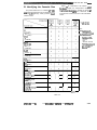
SERVICE INFORMATION
Issued b y C o p y i n g Mach& Quallty Assurance Cerner. C a n o n Inc
MOOEL:
N O . : F-E92-043
DATE: 1992, DEC.
LOCATION
SUBJECT
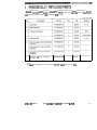
Document Release
NP2020 SERVICE MANUAL For 220/24OV
The SERVICE MANUAL for the NP2020 has been revised to accommodate the
introduction of the NP2120.
AH those concemed are hereby requested to discard the old SERVICE MANUAL
and use the document attached for purposes for which the document is intended.
FY8-13AM-02Y
P r i n t e d in Japan
I m p r i m é au Japon
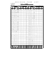
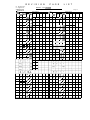
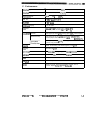
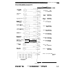
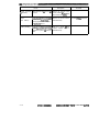
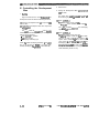
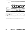
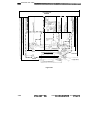
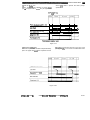
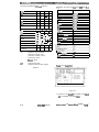
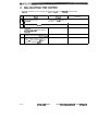
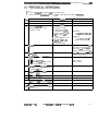
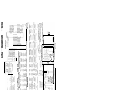
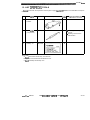
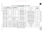
R E V I S I O N
R: Replacement,
S: Supplement,
P A G E
L I S T
MODEL : NP21 20/2020
D: Destroyed,
CHAP
rm P
1
3
GE
1
A
Page 1
RJZVISION
MAY JAN. DEC.
1990 1992 1992
0
+
1R
CHAP
rm
3
PA
GE
3
REVISION
MAY JAN.
1990 1992
0
+
DEC.
1992
1R
lo++
31
0
+
-t
2
32
0
+
+
0
-t +
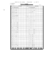
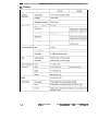
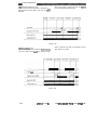
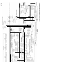
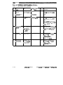
R E V I S I O N
R: Replacement,
S: Supplement,
D: Destroyed,
P A G E
L I S T
MODEL : NP2 120/2020
Page 2
CHAP
.JXR
PA
3
33
0
1R
+
34
0
1R
+
35
0
-t
+
36
0
+
-t
37
0
+
REVISION
MAY JAN. DEC.
GE 1990 1992 1992
CHAP
I-ER
REVISION
PA
MAY JAN. DEC.
GE 1990 1992 1992
3
58
0
-t
1R
4
1
0
+
1R
+
2
0
-t
1R
38
0
1R
-t
3
0 -t
1R
39
0
+
-t
4
0 +
1R
40
0
-t
+
5
0 -f
1R
41
0
+
-t
6
+
1R
42
0
-t
+
70++
42a
-
-
os
so++
42b
-
-
OS
43
0
1R
+
10
0
1R -t
44
0
-t
1R
11
0
-t -t
45
0
+
1R
12
0
+ +
46
0
-t
1R
13
0
+ -t
LS
47
0
-t
-)
47a
-
-
OS
47b
-
-
OS
47c
-
-
os
48
0
>
0
90++
-t +
49
0
+
+
17
0
-f
+
50
0
+
-t
18
0
+
-t
51
0
+
+
19
0
+
+
52
0
-t
+
20
0
+
-P
53
0
-t
+
21
0
+
-t
54
0
+
1R
22
0
+
+
55
0
1R
+
23
0
-t
-t
56
0
+
+
24
0
-t
+
57
0
1R
2R
25
0
+
-+
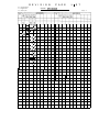
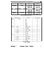
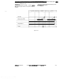
R E V I S I O N
R: Replacement,
S: Supplement,
D: Destroyed,
P A G E
L I S T
MODEL : NP2 120/2020
Page 3
20
-
OS
1R
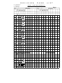
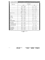
R E V I S I O N
R: Replacement,
S: Supplement,
D: Destroyed,
Page 4
-
OS
1R
24
-
OS
1R
- -
OS
24b - -
OS
25
0
+ -t
26
0
+ +
27
0
-t +
28
0
-t +
29
0
-f +
30
0
-t +
31
0
-t 1R
32
L I S T
MODEL : NP2120/2020
23
24a
P A G E
- -
-
33
0
+ +
34
0
-t -t
R E V I S I O N
R: Replacement,
S: Supplement,
D: Destroyed,
2
1P
4
Page 5
+
+
0
-t +
3P
0
+ +
4P
0
+ +
0
1R
+
6P
0
-t +
7P
0
+ -t
8P
0
1P
-t
0
+
+
+
2P
0
-p +
3P
0
+ +
4P
0
+ +
5P
0
6P
0
-t +
7P
0
+ +
1P
A
+
0
0
-t
+
+
1P
-t
+
2P
0
+ +
3P
0
+ +
4P
5P
0
L I S T
MODEL : PAPER DECK PEDESTAL-Cl
2P
5P
3
0
P A G E
+
+
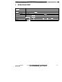
1. FEATURES ............................................
II. SPECIFICATIONS .................................
A. Type .................................................
B. Construction .....................................
C. Pefformance ....................................
D. Others ..............................................
III, NAMES OF PARTS ...............................
A. Externa1 View ...................................
B. Cross-Sectional View .......................
IV. OPERATION ..........................................
A. Control Panel ...................................
B. Making Copies .................................
C. Using the Manual Feed Tray
(NP2020) ..........................................
1,
IMAGE FORMATION PROCESS ..........
A. Outline ...............................................
BASIC MECHANISMS ...........................
A. Functional Construction ...................
B. Electrical Circuitry ............................
C. Inputs lo DC Controller ....................
D. Outputs from DC Conlroller .............
E. Basic Sequence ...............................
ll. EXPOSURE SVSTEM ...........................
A. Varying the Reproduction Ratio.. .....
B. Lens Drive Syiem .............................
C. Scanner Drive System .....................
D. Document Size Identification ...........
III. IMAGE FORMATION SVSTEM .............
A. Outline ..............................................
B. Basic Sequence of Image
Formation .........................................
C. Controlling the Scanning Lamp.. ......
D. Controlling the Primaryflransfer
Corona Current and the Grid Bias
Voltage .............................................
E. Controlling the Development Bias.. ..
F. Measuring the Document Density.. ..
1.
COPYAIEHT 0 1992 C A N O N ING.
1-I
I-2
I-2
I-2
I-3
I-4
I-7
I-7
I-8
I-9
I-9
l-10
l-10
2-1
2-1
3-1
3-l
3-2
3-4
3-8
3-I 1
3-13
3-13
3-14
3-18
3-21
3-24
3-24
3-25
3-26
3-28
3-30
3-33
D. Using the Manual Feed Tray
(NP2120) .......................................... l-10
E. Making Two-Sided Copies ............... 1-I 0
F. Making Overlay Copies. ................... 1-l 1
G. Replacing the CT Unit ....................... 1-i 1
H. Using the COPV DENSITY
CORRECTION Lever.. ...................... I-l 1
1. Atuo-Start (NP2120) ......................... I-lla
V. WARNINGS AND ACTIONS TO TAKE l-12
A. JAM Indicator ( 8% ) ‘........................ I-12
B. ADD PAPER Indicator ( & ) ........... l-12a
C. ADD TONER Indicator ( h ) .......... I-13
D. CONTROL CARD Indicator (w) ... l-13
E. @glndicator.. ................................ l-13
VI. ROUTINE WORK BV THE USER .......... l-14
II. AUXILIARY PROCESSES ..................... 2-6
A. Blank Exposure Mechanism ............ 2-6
B. Ozone Filter ..................................... 2-6
G. Developing Assembly and Drum
Cleaning Unit ................................... 3-36
H. Blank Control ................................... 3-37
1. Controlling the Transfer Corona
Wire Cleaning Mechanism ............... 3-38
IV. PICK-UP/FEED SVSTEM ...................... 3-39
A. Outline .............................................. 3-39
B. Identifying the Cassette Size ........... 3-43
C. Fixing Assembly and Delivery
Assembly ......................................... 3-44
D. Error Detection Circuit (NP2020) ..... 3-47
E. Error Detection Circuit (NP2120) ..... 3-47a
F. Jam Detection .................................. 3-48
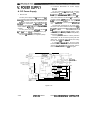
V. POWER SUPPLV ................................... 3-52
A. DC Power Supply ............................. 3-52
B. DC Power Supply for Options .......... 3-53
VI. SERVICE MODES ................................. 3-55
A. Outline.. ............................................ 3-55
B. Using the Service Mode ................... 3-56
VII. SELF DIAGNOSTIC MECHANISM ........ 3-57
C A N O N NP2120/2020 RN.1 DLC. 1592 PRIHTEO IN JAPAN [IMPRIME AU JAPONI
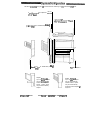
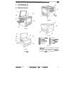
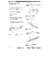
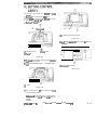
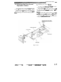
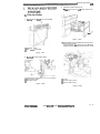
1, EXTERNALS ..........................................
A. Externa1 Covers ...............................
B. Control Panel ...................................
C . Copyboard Cover .............................
D. Fans .................................................
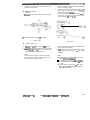
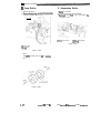
II. DRIVE SVSTEM ....................................
A. Lens Drive Unit ................................
B. Scanner Drive Unit ...........................
C. Main Motor Unit ................................
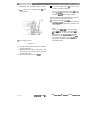
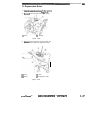
III. FEEDSVSTEM .......................................
A . Pi&Up Unit .....................................
B. Feeder Unit ......................................
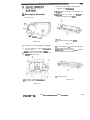
LOCATION .............................................
UNPACKING AND INSTALLING
THE COPIER .........................................
A. Unpacking ........................................
B. Mounting the Dium ..........................
C. Checking the Operation ...................
D. Adding Toner ...................................
4-f
4-I
4-5
4-5
4-5
4-7
4-7
4-9
4-12
4-13
4-13
4-16
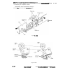
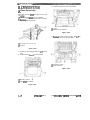
IV. EXPOSURE SYSTEM . ..____._..._______....,.,, 4-18
A. Illuminating Unit ___...._._._._._.___.........,, 4-18
B. Blank Exposure Unit . . . . . . . . . . . . . . . 4-19
v. CORONA SVSTEM _.......___.___.._._..........., 4-21
A. Drum Unit . . . .._................................... 4-21
B. Primarv and Transfer
Coroná Units . . . . . . . . . . . . . . . . . . . . . 4-22
VI. DEVELOPMENT SVSTEM _..__._..........,.. 4-25
A. Developing Assembly . . . . . . . . . ..__.. 4-25
VII. FIXING SVSTEM . . . . . . . . . . . . . . . . . . . . 4-28
A. Fixing Assembly . . . . . . . . . . . . . . . . . . . . . . . . . . . . . . . 4-28
5-I
E. Checking the Image .........................
III. SETTING THE CASSElTE SIZE ..........
IV. SEnlNG THE CT UNIT ........................
V. RELOCATING THE COPIER .................
VI. SETTING CONTROL CARD V ..............
VII. ATTACHING THE DOCUMENT
HOLDER ................................................
5-2
5-2
5-4a
5-5
5-6
5-7
5-8
5-13
5-14
5-15
5-I 7
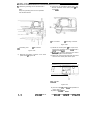
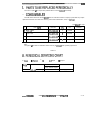
1. PERIODICALLV REPLACED PARTS.... 6-1
ll. CONSUMABLES <.<,...___.......................... 6-2
III. PERIODICAL SERVICING ___....._____...._., 6-3
IV. PERIODICAL SERVICING CHART .,,.._, 6-4
1.
2.
3.
4.
5.
6.
7.
8. DC POWER SUPPLV FOR OPTIONS ..
9. ADJUSTING PCB ..................................
10. PRE-EXPOSURE LAMP ........................
11. AE SENSOR ..........................................
12. HVT ........................................................
13. LIST OF SPECIAL TOOLS ....................
14. LIST OF SOLVENT AND MATERIAL
GENERAL TIMING CHAR-r.. .................
SIGNALSAND ABBREVIATIONS ..........
GENERAL CIRCUIT DIAGRAM .............
WIRING DIAGRAM ................................
DC CONTROLLER PCB ........................
MOTOR DRIVE PCB .............................
DC POWER SUPPLV PCB .._....<.........
A-l
A-3
A-5
A-6
A-ll
A-25
A-26
COPYAIGHT G 1992 CANOH IHC.
A-27
A-28
A-29
A-30
A-31
A-33
A-34
C A N O N NP2120/2MO RB.1 O E C . 1992 PRINTEO IH J A P A N IIMPAIME AU JAPONI
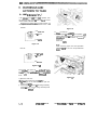
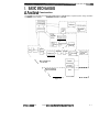
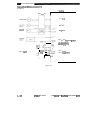
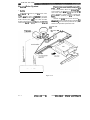
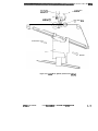
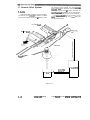
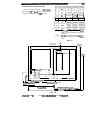
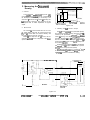
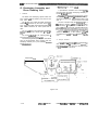
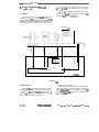
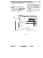
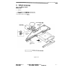
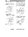
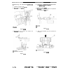
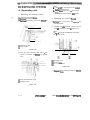
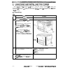
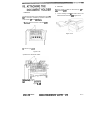
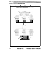
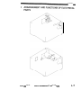
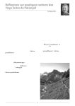
System Configuration
The NP21 20/2020 is designed lo accommodate the following for fully automated copy work:
A stack o f documents
pick-up a n d feed.
ADF-Al
may be placed for automatic
Control Card V
W i t h t h e card. the volume o f copy work
may t e put under watch.
Sorter-Al
U p to 2 0 c o p i e s m a y b e a u t o m a t i c a l l y s o r t e d or
g r o u p e d b y page.
MSAl
U p lo 10 c o p i e s may b e a u t o m a t i c a l l y s o r t e d or
g r o u p e d b y page.
\Q-rl
COPYRICHT G 1592 CANON INC.
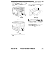
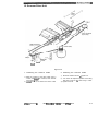
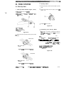
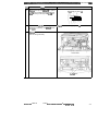
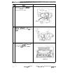
Stapler Sorter-B2
Up to 10 sets of copies
may be automaiically
sorted and stapled.
Further, sorted copies
may be automatically
stapled.
I
Paper D e c k P e d e s t a l
Stapler Sorter-Bl
Up to 10 sets of copies
may be automatically
sorted. Further, copies
may be automatically
sorted and then stapled in
sequence.
C A N O N NP2120/2020 R E Y . 1 UEC. 1992 PRINTEO I N J A P A N IIMPAIME AU JAPONI
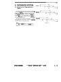
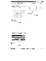
CHAPTER 1
GENERAL DESCRIPTION
1.
II.
III.
IV.
FEATURES.. .........................................
SPECIFICATIONS ................................
NAMES OF PARTS ..............................
OPERATION.. .......................................
COPYRIGNT 0 1992 C A N O N ING.
I-1
1-2
l-7
1-9
V. WARNINGS AND ACTIONS
TOTAKE .............................................. I-12
VI. ROUTINE WORK BY THE USER.. ....... 1-14
C A N O N NPZl20/2MO KV.0 M A Y 1990 PAINTEU I N JWAN IIMPRIME AU JAPONI
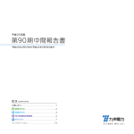
l.GENERALDESCRIPTION
BW3
1. Front-loading.
- Thecopier is designed to aCCept cassettes from the frOnt for ease of use (two cassettes holding 250 sheets
each).
- The copier is given two cassette holders, thereby eliminating the need forcassetle replacement in making
copies of different sizes.
- The copier’s multifeeder allows you to feed multiple postcards (NP21 20)
2. Full line of auto mechanisms.
- The copier has an auto paper selection mechanism as standard, which selects paper of the correct size
in response to placement of a document.
- With the auto reproduction ratio selection mechanism, the copier calculates the correct reproduction ratio
according to the specified copy size.
- The AE (auto exposure) mechanism ensures crisp reproduction of newspapers and blue-print documents.
- Thecopier’s auto-stafifeature lest you press the COPY START key during the wait period so thatthe copier
will start making copies as soon as it becomes ready (NP2120).
3. HQ jumping toner.
* The copier uses Canon? own HQ (high quality) jumping toner for reproduction of clear characters and
photos.
- The toner is of a single-component type, which provides stable images.
- In addition, a 30-dia. high sensitivity OPC drum is used to enable enhanced image reproduction and a
compact copier design.
4. Man-machine interface.
- As many as 21 copies (A4, landscape) may be made per minute.
. The zoom mechanism allows reduction down to 50% and enlargement up to 200% of the original image.
- The page separation mode serves to speed up copying book-form documents.
- The copier accepts documents as small as a postcard oras large as A3.
- With the CT unit (option), the copies may be in red, green, blue, or brown.
5. A variety of options to choose from for full automation.
The copiercommunicates with its options at a higher speed than ever, resulting in more output
* With options, up lo 21 copies/min; 1:l (A4, landscape).
- ADF-Al for automatic document feed.
- Sorter-Al for automatic sorting and grouping (20 bins).
- MS-Al for automatic sorting and grouping (IObins).
- Control Card V (configured as built-in) for copy volume control (up to 200 depts.).
- Stapler Sorter 1 O-BI for stapling copies sorted in its ten bins.
COPYAIOHT D 1592 C A N O N I N C .
C A N O N NPZK?O/ZMO RN.1 OEC. 1992 PAINTEO IN JAPAN [ I M P R I M E AU JAPONI d
pergiventime’.
l-l
i.GENERAL DESCRIPTION
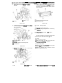
Pa. Type
Body
Desktop
Copyboard
Fixed
Light source
Halogen lamp 1 OO/1 15V model 300W
220124OV model _._ 330W
Lens
Zoom lens
Photosensitive medium
OPC
ES. Construction
Copying
Indirect static photocopying
Charging
Corona
Exposure
Slit (moving light source)
Copy density adjustment Automatic (AE) or manual
Development
Pick-up
Dry
Automatic
2 cassettes; multifeeder (NP2120)
Manual
Manual feed tray (NP2020)
Transfer
Corona
Separation
Curvature and Static eliminator
Cleaning
Blade
Fixing
Heat roller (900 W)
1-2
COPYRIGHT 8 1992 C A N O N ING.
C A N O N NPZl20/2020 AN.I O E C . 1992 PAINTEO I N J A P A N IIMPAIME AU JAPONI
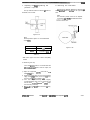
C. Performance
Document type
Sheet. Book, 3-D object (2 kg14.4 Ib max.)
Jocument size (max.)
A3 (297X420 mm)/LDG (1 l”X17”)
qeproduction ratio
See Table l-1 ; 50% to 200%, zoom.
Nait time
90 sec or less (20°C/680F)
?rst copy
9 sec or less
:ontinuous copying
1 to 99 copies
Zopy size
A3/LDG (297 x 431.8 mm) max. (11 in x 17 in)
Postcard (100 x 148 mm) min. (3.9 in x 5.8 in)
:~PY we
Cassette
Plain paper (64 to 80 g1m2), Tracing paper (SMI), Colored paper
Manual feed tray
Plain paper (64 to 128 g/m2), Tracing paper (SMI, GNT80’).
Colored paper, OHP film, Postcard, Label
* NP2020 only.
“;alc,,,
Plain paper (64 to 128 g/m’), Colored paper, OHP film
(overlay only), Postcard
:assette
Claws, Front loading; 250 sheets (approx.) of 80 g/m2
:opy tray
99 sheets (80 g/m2)
don-image width
2.0 mmI0.08 in (leading edge), 2.5 mm/O.l in (left/right)
\uto clear mechanism
Provided. (2 min, standard; may be disabled)
iuto shut-off mechanism
Not provided.
iuto starl
NP2120 only.
Sorter-Al, MS-Al, Paper Deck Pedestal, Control Card V,
CT Unit, Stapler Sorter-BI, Stapler Sorter-62
COPYAIGHT 6 1992 C A N O N ING.
C A N O N NP2120/2020 REY.1 OEC. 1992 PAINTED I N J A P A N IIMPRIME AU JAPONI
l-3
- I.GENERALDESCRIPTION
B. Others
l-4
COPYRIGNT 0 1992 CANON INC.
C A N O N NPZl20/2MO NH.2 DEC. 1 9 9 2 PRINTEO I N J A P A N IIMPRIME AU JAPONI d
l.GENERALDESCRIPTION
DIRECT
REDUCE
m
ENLARGE
100/220/24OV
1 : 1 (kO.5%)
1
1
1
1
: 0.500 (kl .O%)
:0.700 (d.O%)
:0.816 (d.O%)
:0.865 (fl.O%)
1
1
1
1
: 1.154(+1.0%)
: 1.224(fl.O%)
: 1.414 (fl.O%)
:2.000 (kl.O%)
115v
1 : 1 (?0.5%)
1
1
1
1
:0.500(*1.0%)
:0.647 (il.O%)
:0.773 @l.O%)
:0.786(+1.0%)
1 :1.214(+1.0%)
1 : 1.294(*1.0%)
1 :2.000 (*l.o%)
220/240 V
1 : 1 @0.5%)
1 :0.500 (*l.o%)
1 : 0.707(+1.0%)
1 : 1.414 (kl.O%)
1 :2.000 (kl.O%)
Table I-l Fixed Reproduction Ratio
Table l-2 Copy Speed
COPYNIGNT t? 1992 C A N O N I N C .
C A N O N NPZl20/ZMO NN. M A Y 1990 PRINTEO I N J A P A N IIMPNIME AU JAPON)
1-5
Table l-3 Paper Size
1-6
COPYAIGNT 0 1592 CANON INC.
C A N O N NPZl20/2020 R N . 0 M A Y 1990 PRINTEO I N J A P A N IIMPNIME AU JAPON]
l.GENERALDESCRIPTION
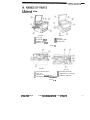
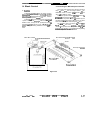
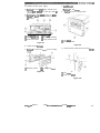
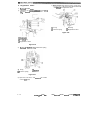
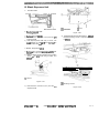
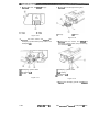
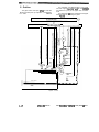
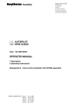
A. Externa1 View
NP2020
0
@
@
@
Copy tray
Copyboard cover
POWER switch
Delivery unit cover
NP21 20
0 Cassette
@ Copyboard glass
0 Control panel
Figure 1-l
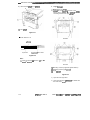
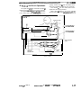
NP2020
NP21 20
Fixing assembly knob
0 Developing assembly
Drum unit
c3 Registration knob (NP2120)
Delivery unit release lever
0 Multifeeder (NP2120)
Developing assembly release lever
Figure I-2
COPYNIGNT 0 1992 C A N O N I N C .
C A N O N NP2120/2020 NEV.1 DEC. 1992 PAINTM I N J A P A N IIMPRIME AU JAPONI
1-7
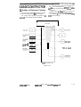
1,GENERALDESCRIPTION
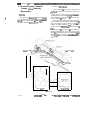
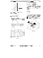
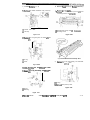
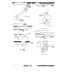
5. Cross-Sectional View
1. NP2020
Figure l-3
@ No. 3 mirror
@ No. 2 mirror
@ No. 1 mirror
@ Scanning lamp
@ Copyboard glass
@ Copyboard cover
Q Lens
@ Pre-exposure lamp
@ Primafy corona unit
@0 No. 6 mirror
1-8
@I No. 5 mirror
@ No. 4 mirror
@ Manual feed pick-up roller
@ Manual feed tray
@ Vertical feed roller 1
@ Vertical feed roller 2
@I Cassette 1 pick-up roller
@ Cassette 2 pick-up roller
@ Registration roller
@ Transfer corona unit
COPYNIGNT f3 1592 C A N O N ING.
@l
@
8
@
0
0
@
8
0
Static eliminator
Photosensitive drum
Cassette 1
Cassette 2
Feeder unit
Ozone filter
Exhaust fan
Fixing unit
Delivery roller
C A N O N NPZl2LVZMO AW.0 MAY 1990 PAINTED IN JAPAN IIMPRIME AU JAPUNI
1. G E N E R A L D E S C R I P T I O N W
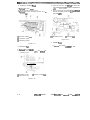
2. NP2120
Figure l-3 a
@
Q
@
@I
@
@
Q
@
@
@9
No. 3 mirror
No. 2 mirror
No. 1 mirror
Scanning lamp
Copyboard glass
Copyboard cover
Lens
Pre-exposure lamp
Primary corona unit
No. 6 mirror
CWYRIGHT c 1932 C A N O N ING.
@
@
@
@
@
@
0
@
@
@
No. 5 mirror
No. 4 mirror
Manual feed roller
Manual feed pick-up roller
Vertical feed roller 1
Vertical feed roller 2
Cassette 1 pick-up roller
Cassette 2 pick-up roller
Registration roller
Transfer corona unit
@
@
@
@
@
@
@
@
@
Static eliminator
Photosensitive drum
Cassette 1
Cassette 2
Feeder unit
Ozone filter
Exhaust fan
Fixing unit
Delivery roller
C A N O N NPZl20120’20 R N . 0 OK. l!X2 PRINNI I N J A P A N IIMPRIME AU JAPONI
l-8a
1 GENERAL DESCRIPTION B
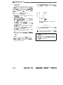
A. Control Panel
1. NP2020
AIBIINCH SIZE
A SIZE
Figure l-4
0 PAGE SEPARATION key
Press the key to select the page separation
mode.
Q SORTIGROUP key
Press the key to select the SORTIGROUPINONSORT mode; when the indicator is OFF, the nonsort mode is selected.
@ FIXED RATIO indicator
@ JAM location indicator
@ JAM indicator
@ CONTROL CARD indicator
@ ADD TONER indicator
@ ADD PAPER indicator
@ AUTO RATIO key
Press the key to select the auto reproduction
mode; effective only when an ADF is attached.
@ COPY COUNT indicator
- Apressonthe% keyindicatesthe reproduction
ratio (%).
- The count decreases for each copy made.
0 % key
Holddownthe keytocheck the reproduction rabo
shown on the COPY COUNT indicator; the indication goes OFF 2 sec after the key is released.
@I RESETkey
Press the key to return to the standard mode:
- C o p y
c o u n t
1
DIRECT
- Ratio _......._...._.......................
NON-SORT
- M o d e .._._..._..._.....................
OFF
* AE ._................._.....................
COPYAIGNT % 1992 C A N O N I N C .
@ PRE-HEAT key
A press on the key in the standby mode activates
the pre-heat mode.
- All LEDs except the PRE-HEAT indicator and
POWER indicator will go OFF.
- The fixing temperature will be controlled at
14O”C/284”F.
@ POWER switch
@ POWER indicator
The indicator remains ON when the POWER
switch is ON.
@ TENKEY pad
0 CLEARISTOP key
Q COPY START key
- If red, no copy can be made.
- If green, copies may be made.
@ ZOOM key
Press the key to select the desired reproduction
ratio between 50% and 200% in 1% increment.
@ CASSETTE SELECT key
@l FIXED ENLARGEMENT key
@ DIRECT key
@ FIXED REDUCE key
@ COPY DENSITY key
@ AE key (automatic exposure control)
C A N O N NP2l20/2MO REY.0 MAY 1990 PAINTEO IN JAPAN [IMPRIME AU JAPON] d
l-9
Figure l-4a
@ PAGE SEPARATION key
Press the key to select the page separation
mode.
@ SORTIGROUPISTAPLE SORT key
Pressthekeytoselectthesort,group,StapleSOrt,
or non-sort mode.
The copier is in the non-soti mode when the
indicator is OFF.
@ FIXED RATIO indicator
@ JAM location indicator
@ JAM indicator
@ CONTROL CARD indicator
0 ADD TONER indicator
@ AUTO ZOOM key
Press the key to select the auto zoom feature.
@ COPY COUNT indicator
- indicates the ratio when the % key is pressed.
- incremented for each copy during copy operation.
@l % key
Hold down the key to change the COPY COUNT
indicator notation from ratio to copy count.
Upon release, the notation is replaced by the
copy count in 2 sec.
@ RESETkey
Press the key to return to the standard mode:
copy count 1, DIRECT, non-so& AE (may be
deactivated).
@ PREHEAT key
Pressthekeyduringthestandbyperiodtochoose
the preheat mode.
* All LEDs except the PREHEAT and POWER
indicators on the control panel go OFF.
@ POWER switch
@ POWER indicator
The indicator remains ON when the POWER
switch is ON.
@ TENKEY pad
0 CLEAR/STOP key
@ COPY START key
- when itflashesgreen, youcannot makecopies.
- when it remains green, you can make copies.
- it remains red during copy operation.
@ ZOOM key
Press the keywhen selecting a reproduction ratio
between 50% and 200% in lo/, increments.
@ CASSETTE SELECT key
@I ENLARGE key
@ DIRECT key
@ REDUCE key
@J COPY DENSITY key
@I AE key (automatic density adjustment)
l -9a
CANON NPZl20/2MO NN. OEC. 1592 PAINTEO IN JAPAN (IMPRIME AU JAPONI d
COPYRICNT 0 1592 C A N O N I N C .
- ,.GENEWLDESCRIPTION
->.s.
,~
M
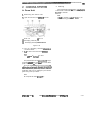
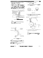
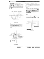
B. Making Copies
1) Tum the POWER switch ON
If the temperature of the fixing assembly is
below the specified value,
. NP2020
The COPY START key remains red.
. NP2120
The COPY START key flashes green.
If the temperature of the fixing assembly is
above the specified value, the COPY START
key goes green.
The wait time is normally 90 sec (2O”C,
average).
2) Openthecopyboardcover,andplaceadocument
face down aligning ti with the size index.
3) Press the DIRECT, REDUCE, ENLARGE, or
ZOOM key for the desired copy size.
4) Press the AE key, and press the COPY DENSITY
key as necessary if manual adjustment is desired.
5) Check the size of the cassette.
0 Replace the cassette if it does not contain
paper of the desired size.
6) PresstheTENKEY padtosetthedesirednumber
of copies (1 to 99), and check the COPY COUNT
indicator.
0 Press the CLEARBTOP key 10 correct any
mistake; set the copy count thereafter.
7) Press the COPY START key.
@ If the CLEARISTOP key is pressed in the
continuous copy operation. the copier stops
after it has completed the copy run.
@ The adjustment mode for density may be
switched from automatic to manual between
when the operation is started and when the
last copy is completed; however, switching
from manual to automatic is not possible
during the period.
0 After each copy operation or a key operation,
the copier returns to the standard mode ti left
alone for about 2 min’.
‘Cannot be changed. but may be de-activated.
C. Using the Manual Feed Tray
(NP2020)
1) Set a document on the copyboard.
2) Press the DIRECT, REDUCE, ENLARGE, or
ZOOM key.
3) De-activate the AE mode, and adjust the density
using the COPY DENSITY lever if manual
adjustment is desired.
4) Feed a sheet of copy paper along the guides on
the manual tray.
0 The copier automatically starts copying as
soon as it detects the copy paper.
0 Make sure sheets are fed at intervals of 50
mm or more if in the continuous copy mode.
Note:
When the ADD PAPER indicator is ON, the
COPY READY indicator is red; manual feed
operation, however, is still possible.
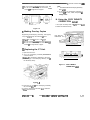
. Using the Manual Feed Tray
(NP21 20)
1) Set the document on the copyboard.
2) Open the manual feed tray.
3) Set the slide guide to suit the paper size.
Note:
Slide out the sub tray as necessaty to suit
larger paper sizes.
Note:
If the copy is too dar& or light in the AE mode,
de- activate the AE mode, and make copies
while varying the density using the COPY
DENSITY key.
@ If the ADD PAPER indicatorcomesONdur¡ng
copy operation and the operation stops, add
paper to the cassette; a press on the COPY
START key thereafter causes the copier to
make the remaining number of copies.
@ IfanADFisattachedtothecopier.documents
placedonthetraywill beautomaticallypicked
upandcopiedwhentheCOPY STARTkeyis
pressed.
l-10
COPYRIGNT % 1992 C A N O N I N C .
4) Insert as many sheets as necessary along the
guide until they stop; keep the face of the copy
paper up.
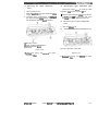
E. Making Two-Sided Copies
Make sure that the copy is oriented the same way
(front and rear) for both first and second sides: keep
the following in mind:
0 Check the paper is not moist or curled;
0 Check the paper is of 64 to 128 g/mZ;
C A N O N NPZl20/ZMO RN.1 OEC. 1992 PAINTEO I N J A P A N IIMPAIME AU JAPONI
1. G E N E R A L D E S C R I P T I O N
@ Do not process each side more than once; and
@ Do not use both overlay and two-sided copy
modes on a single sheet of paper.
Note:
1.
Donottiltorshakethedevelopingassembly
or CT unit.
2. Do not place the developing assembly or
CT unit on the floor; rather, keep them in
storage boxes.
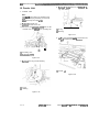
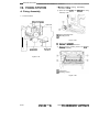
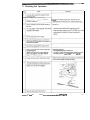
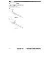
H. Using the COPY DENSITY
CORRECTION Lever
If the copies are always dark or light, slide the lever
to obtain the desired density.
Figure l-5
F, Making Overlay Copies
Byreplacing thedeveloping assembly, thecopymay
carry two colors; keep the following in mind:
COPY DENSITY
CORRECTION lev
0 Check the paper is of 64 to 128 glm’;
Q Do not process each side more than twice; and
@ Do not use both overlay and two-sided copy
modes on a single sheet of paper.
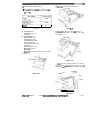
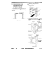
G. Replacing the CT Unit
1) Open the front door.
2) Turn the developing assembly release lever
counterclockwise.
3) Slide out the developing assembly to the front.
4) Hold the grip of the developing assembly, and lift
the assembly slowly.
Figure 1-7 COPY DENSITY
CORRECTION Lever
Figure l-6
5) Place the CT unit on the developing assembly
rail, and slide it in.
6) Turn the developing assembly lever clockwise.
7) Close the front door.
COPYAIGHT 0 1992 C A N O N ING.
C A N O N NPZl20/2MO REV.I O E C . 1592 PAINTED I N JAPAN (IMPAIME AU JAPONI
i-ll
WZ33
1,GENERALDESCRIPTION
1. Auto-Start (NP21 20)
The START indicator goes and remains red when
you press the COPY START key during warm-up,
and copy operation starts as soon as warm-up is
completed.
- You can press the COPY START key while the
wire is being cleaned or during the jam wait
period.
. You still have access to the DENSITY key, AE
key. RESETkey,orSTOPkeyafteractivatingthe
auto-start mode.
- To cancel the auto-starl mode, press the RESET
or CLEAR/STOP key.
Note:
The autostart mode will automatically be
canceled if the cassette has run out of paper,
if the control card is not inserted, or if the right
door of the cassette holder is open.
l-11 a
COPYAIGHT 0 1992 C A N O N I N C .
C A N O N NPZl20/2MO R N . 0 WC. IB2 PRINTED I N J A P A N I M P R I M E AU JAPON)
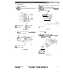
KBld l.GENERALDESCRIPTION
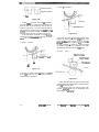
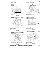
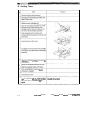
A. JAM Indicator ( 8% )
If the indicator goes ON during copy operation, take
the following steps; a jam is likely to have occurred
at the location indicated.
Forjamsinanyoftheoptions(sorterorADF),see
the respective service manual.
NP2020
Figure 1-9
J a m in ADFunit
Jam in
copier
IJ a m in sorta
Figure 1-8
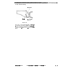
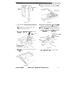
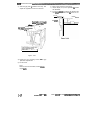
5) Close the delivery unit cover.
6) Check if paper is jammed in the separation unit/
feeder unit; if paper is found, turn the feeder unit
release lever counterclockwise to release the
feeder unit.
Work with care.
Note:
When removing paper from the separation
unit, take care not to touch the photosensitive
NP2120
drum.
J a m in A D F unit
Jam in
copier
J a m in sorter
Figure 1-8 a
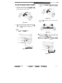
If the jam is in the copier, be sure to check the pickup unit, separation unit/feeder unit, fixing assembly/
delivery unit, and drum unit to remove all paper
found.
Figure 1-l 0
1) Open the front door.
2) Remove the copies from the copy tray.
3) Pull the grip of the delivery unit to open the
delivery unit cover.
4) Check if paper is jammed in the fixing assembly;
if paper is found, turn the fixing assembly knob
clockwise to remove it.
1-12
COPYNIGHT 0 1592 C A N O N I N C .
C A N O N NPZl2W'MO REV.1 OEC. 1 5 9 2 PAINTEO I N J A P A N IIMPRIME AU JAPON)
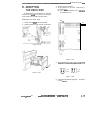
7) Open the right cover, and check if paper is
jammed; remove the paper, if any.
Furiher, check that no paper is sticking out of the
cassette.
1. Using the Multifeeder Tray (NP2120)
Lift the lever, and pull out the jam, taking care not to
tear the paper.
\
Right cover
Figure l-12a
Figure l-ll
B. ADD PAPER Indicator ( & )
The indicator goes ON if no cassette is in the
cassette holder or the cassette has no paper.
1) Slide out the cassette to the front of the copier.
2) Put paper in the cassette.
3) Slide the cassette back into the copier.
Figure 1-lla
8) Close the right door, and then the front door
COPYAIGNT 0 1992 C A N O N ING.
C A N O N NPZlZO/ZG70 NEW.0 DEC. 1592 PRINlID IN JAPAN IIMPRIME AU JAPON)
l-12a
C. ADD TONER Indicator ( h )
The indicator goes ON when the black developing
assembly is running out of toner.
1. Black Developing Assembly
1) Open the front door.
Turn the black developing assembly lever
counterclockwise.
3) Pull the black developing assembly to the front
until it stops.
4) Open thetoplidofthe blackdeveloping assembly.
5) Shake the toner cartridge side to side about ten
times.
6) Placethetonercartridgeontheblackdeveloping
assembly.
7) Hold the toner cartridge, and pull the seal to the
front until a resistance is felt.
2. CT Unit (mono color developing unit)
If the image seems too light in parts of a mono color
copy, the CT unit is likely to be running out of mono
colortoner; replace the unit if this happens. If the CT
unit is placed in the protection box and shaken, the
problem may be corrected temporarily.
Note:
2)
The CTunit isof adisposabletype;donot
toner. but use a new unit.
add
D. CONTROL CARD Indicator
Gs)
The indicator flashes in response to the following
conditions while the control card is in the copier.
1
2
The control card is not properly inserted into the
control card unit.
The control card unit indicates ‘P’ or ‘EE’ even
when the control card is properly inserted into
the control card unit.
E. @ @ Indìcator
Any of the foilowing goes ON if a document is left
behind, the sorter is detached. or the right door is
open.
Figure 1-12
8)
Tap the topofthetonercartridgeso that all toner
remaininginthecartridgefalls intothedeveloping
assembly.
9) Detach the toner cartridge with care.
10) Closethetoplidoftheblackdevelopingassembly.
11) Slide the black developing assembly into the
copier.
12) Turn the developing assembly release lever
clockwise.
13) Close the front door.
NP2020
NP21 20
@ Document is left behind.
Q Sorter is detached.
@ Right door is open.
COPYAIGHT 0 1 9 3 2 CMGH INC.
CAGGG Wl20/2MO RN.1 DIC. 1992 PRINTEG IN J A P A N IIMPGIME AU JAPONI
1-13
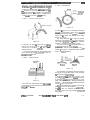
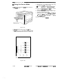
Advise the user to clean the following once a week
without fail:
1) Primary Corona Wire
Slide in and out the cleaning wire to clean it.
2) Copyboard Glass
Wipe it using a moist cloth; thereafter, wipe it
using a dry cloth.
3) Copyboard Cover
Wipe it using a mild detergent solution; thereafter.
wipe it using a dry cloth.
4) Static Eliminator
Clean the static eliminator using the cleaning
brush (accessory).
If separation jams occur frequently, clean the
static eliminator using the cleaning brush
(accessory) as necessary.
1-14
C O P Y A I G N T Q 1992 CANON INC.
C A N O N NPZlZO/ZGZl RN.1 JAN. 1992 PRINTEG IN JAPAN [IMPRIME AU JAPONI
CHAPTER 2
COPYING PROCESS
1.
IMAGE FORMATION PROCESS . ...<....
COPYGIGNT 0 1992 CANOH ING.
2-1
II.
AUXILIARY PROCESSES . . . . . . . . ..__.._..___
CANOH NPZl20/2tVl AEV.0 MAY 1990 PRINTEO I N J A P A N [ I M P R I M E AU JAPON)
2-6
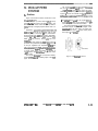
C o p y b o a r d glass
I
,
,I
j “‘y>
(
Scanning lamp
Lower fixing roller
Sfatic eliminator
Transfer corona unit
Figure 2-1
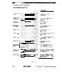
1, See Figure 2-l for the construction of the copier
Images are formed in the following eight steps:
Step 1
Step 2
Step 3
Pre-conditioning exposure
Primary corona exposure (negative DC)
Image exposure
COPYRIGHT 0 1992 C A N O N I N C .
Step 4
Step 5
Step 6
Step 7
Step 8
Development (AC and negative DC)
Transfer corona exposure (negative DC)
Separation
Fixing
Drum cleaning
C A N O N NPZl20/2020 AEV.0 M A Y 1990 PRINTEO IN JAPAN IIMPAIME AU JAPONI
2-l
F o r m a t i o n o f Electrostatfc Latent I m a g e Separation
r - - - - - - - - - - - - - - - - - --------_ 1
I
I
3.
I
I
Image exposure
J
I
/
r--
1. P r e - c o n d i t i o n i n g e x p o s u r e
I
4 . Development
L-----+-------J
8 . D r u m cleaning
5 . Transfer c o r o n a exposure
M a n u a l f e e d tray
R
Delivery
>(
ti
6. separaion
Registration
L9
7 . Fixing
CFiSSt3te
0 Flow o f copy paper
CXSWk
c Rotation o f d r u m
Figure 2-2
The photosensitive drum is of a two-layer construction; its outer layer is made of organic photoconductor (OPC), and the inner layer is an aluminum base
made of conducting material.
Time
lz
Photoconductlng
Iayer
(1) -
F
O
s
g
å ‘/
L?!
L
,
/
I/
r-- - - T
Light area
/
- 5 0 0\
Pre-conditioning Primary corona
D a r k area
(step 1 ) (step 2 )
I
I I m a g e e x p o s u r e (step 3)
Figure 2-3
Figure 2-4
2. Formation of Electrostatrc Latent Image
This block consists of the first three steps of the
image formation process; at its end, the areas of the
drum corresponding to dark areas of the document
areleftwith negativecharges, andthoserepresenting
light areas are rid of negative charges.
The pattern of charges so formed is not visible to
the human eyeand, therefore, iscalled an electrostatic
latent image.
3. Step 1 Pre-conditionrng exposure
Figure 2-5
2-2
COPYAIGHT 0 1992 CANON ING.
C A N O N NP2120/2MO R N . 0 M A Y 1990 PRINTEO I N J A P A N IIMPAIME AU JAPONI
I
C O P Y I N G P R O C E S S K#ZW
Inthisstep,orpre-conditioningexposure,thesurface
of the drum is exposed to light from the preconditioning exposure lamp. All charges remaining
on the surface of the drum from the preceding copy
cycle are eliminated in preparation for exposure by
theprimarycorona. Suchcharges, if leftastheyare,
could result in copies with uneven density.
4. Step 2
6. Step 4 Development
,Blade
Developing
cylinder
Primary corona exposure
Figure 2-8
Figure 2-6
In this step, the drum is exposed by the primaiy
corona. As a result, its surface will cometo have a
uniform layer of negative charges and maintain
primary potential.
The surface potential of the drum is determined
by the value of the grid bias’grounded by way of a
constant voltage element.
5. Step3
As shown in Figure 2-8, the developing assembly
consists of a developing cylinder and a magnetic
blade; the developing cylinder itself is made up of a
magnet fixed in position and acylinder which rotates
around the magnet.
The black developer is a single-component
developer of magnetite and resin. The developer
has insulating properties and is charged to a positive
potential by friction with the rotating cylinder.
The color developer is a fixed-ratio mixture of
carrier (iron powder) and toner (resin).
By friction with the rotating cylinder, the iron
powder is charged to a negative potential, and the
toner to a positive potential.
Image exposure
Opwal i m a g e
Dark_area
,l I 1
1
Lightarea
Figure 2-7
In this step, the optical image of the document is
projectedonthesurfaceofthedrumtoneutralizethe
charges in light areas.
COPYRIGHT 0 1992 CANON INC.
Magnet
Magna
Figure 2-9
Aconcentrated magneticfield develops between
the magnet and the tip ofthe blade, and the developer
is attracted to the magnetic field.
The magnetic field holds the developer it has
attracted virtually immobile and creates a collection
of developer particles hanging from the tip of the
blade. Asthecylinderrotates, thedeveloperparticles
leavethe magneticfieldtodepositthemselvesonthe
cylinder in a thin, uniform layer.
Since both thedeveloping cylinder and blade are
given AC bias and DC bias (negative component) at
the same time, the resulting waveform of the
developing bias has a larger negative component
than positive.
C A N O N NPZl20/2MO REY.0 MAY 1990 PAINTEO IN JAPAN [IMPRIME AU JAPONI
2-3
8. Step 6 Separation
D C bias
Figure 2-10
During copy operation, the toner is attracted to
the drum by the work of the surface potential of the
drum as well as the developing bias (at time of
positive component), and it turns the electrostatic
latent image to a visible image. The excess toner is
repelled by the surface potential ofthe drum and the
developing bias (at time of negative component).
A DC bias affects copydensity; a larger bias, Le.,
approaching OV, increases the density but, at the
same time, tends to cause fogging.
7 Step 5 Transfer
\ Static eliminator
Figure 2-12
In this step, the paper is separated from the drum
making use of the rigidity of the copy paper. Thin
paper, with little rigidity, however, tends to remain in
contact with the drum; to prevent such a condition,
the static eliminator is charged to a positive potential
to facilitate separation by weakening the static
attraction between the drum and copy paper.
9. Step7
Fixing
, Oil application roller
Transfer c o r o n a mi!
-r-L
F-4
, upper lixing roller
Halogen heater
4
Figure 2-11
In this step, a negative corona is applied to the back
of the copy paper so as to attract the positively
charged toner to the paper.
Figure 2-13
In this step, the paper carrying a transfer image
moves between two heated rollers, and the transfer
image is fixed to the paper.
To prevent jams and toner offset, the upper roller
remains in contact with the oil application roller
impregnated with silicone oil.
2-4
COPYAIOHT 6 1992 C A N O N I N C .
C A N O N NP2120/2MO RN.0 MAY 1990 PRINTEO IN JAPAN [IMPRIME AU JAPON)
10. Step 8 Drum cleaning
Cleaning b l a d e
\
Scoop-up s h e e t
Blade
Figure 2-14
In this step, the toner remaining on the drum surface
is scrapedoff by thecleaning blade and collected by
the scoop-up sheet in preparation of the next copy
cycle. The toner is then moved aside by the blade.
COPYAIGNT Q 1592 CANON INC.
C A H O N NPZl20/2MO KV.0 M A Y 1540 PAINTEO IN JAPAN IIMPRIME AU J A P O H ,
2-5
FZB3COPYlNGPROCESS
A. Blank Exposure Mechanism
The blank exposure mechanism is used to remove
the potential from the non-image sections of the
drum in the REDUCTION mode or lo suit paper
sizes; see p. 3-37.
The light from the pre-exposure lamp is reflected
by the reflecting plate and directed onto the
photosensitive drum.
The non-image section between two sheets of
copy paper is kept free of toner by lowering the grid
bias of the primary corona unit, instead of using the
blank exposure mechanism to remove the potential
of the drum.
B. Ozone Filter
The fan unit is equipped with an ozone filter, which
breaks down the ozone generated by the coronas
into oxygen by catalytic action.
2-6
COPYAIGHT 0 1592 C A N O N ING.
C A N O N NPZlZO/ZMO R N . 0 MAY 1990 PAINTEO I N J A P A N IIMPRIME AU
JAPONI
CHAPTER 3
OPERATIONS AND TIMING
Inoutlinediagrams,-- representsmechanícaldrivepaths,andmindicateselectricalsignal
paths.
Signals in digital circuits are identified as ‘1’ for High and ‘0’ for Low. The voltage of signals,
however, depends on the circuit.
Nearly all operations of the copier are controlled by microprocessors; the interna1 workings of
these processors are not relevant to the serviceman’s work and, therefore, left out of the
discussions. By the same token, no repairs are prescribed for the PCBs at the user’s premises;
for this reason, PCBs are discussed by means of block diagrams rather than circuit diagrams.
Forthe purpose of explanation, discussions are divided into the following: from sensors to DC
controllerPCBinputports;fromDCcontrolleroutputportstoloads;andminorcontrolcircuitsand
functions.
1.
II.
III.
IV.
BASIC MECHANISMS.......................... 3-1
EXPOSURE SYSTEM .......................... 3-13
IMAGE FORMATION SYSTEM ............ 3-24
PICK-UP/FEED SYSTEM .................... 3-39
COPYRIGHT 0 1992 C A N O N ING.
POWER SUPPLY ................................. 3-52
V.
VI. SERVICE MODES ................................ 3-55
VII. SELF DIAGNOSTIC MECHANISM.. ..... 3-57
C A N O N HPZl20/2GZO RN.0 MAY 1990 PAINTEU IN JAPAN [IMPRIME AU JAPON]
O P E R A T I O N S A N D TIMING EXE&3
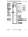
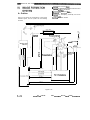
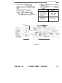
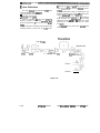
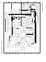
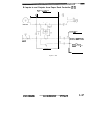
14. Functional Construction
The copier can be divided into four functional blocks; pick-up/feed system, exposure system, image formation
system, and control system.
-
-
\
\
\
-
-
-
-A
-
-
Pi&uplfeed s y s t e m
---- 1
t---------,
Paperdeckpedestal
\
\
.\
\
-
-
-
-
-
-
-
-
---- -l
Figure 3-1
COPYAIGHT 0 1992 UINON I N C .
C A N O N NPZl20/2lVO AEV.tl MAY 1590 PRINTED I N JAPAN IIMPAIME AU JAPONI
3-1
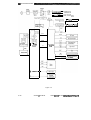
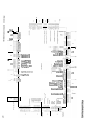
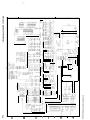
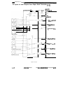
B. Electrical Circuitry
The copier is controlled by the two microprocessors
and communication LSI on the DC controller PCB,
each of which functions as follows:
1 Microprocessors 1
Q301 (master)
. Controls the copy sequence.
. Controls the document size identification.
Note:
The main motor (Mi) is a synchronous motor
thatusesthefrequencyofthepowersupplyas
referente. The scanner motor (M2) and lens
motor (M3), on the other hand, are stepping
motors that use the oscillation frequency of
the crystal oscillator built in the DC controller.
As such, luctuations in the power supply frequency during copy operation in turn fluctuate
the main motor (MI), causing the copies to
carry expanded or contracted images.
Q302 (slave)
. Controls the stepping motor.
. Outputs the image formation control signals.
Q304 (IPC)
. Controls the serial communication with ADF
and sorter.
Note:
With the built-in A/D converter, the copie&
microprocessors can read both digital and
analog signals.
3-2
COPYAIGHT 0 1992 C A N O N I N C .
C A N O N NPZl20/2MO RN.0 M A Y 1990 PAINTEO I N J A P A N IIMPAIME AU JAPONI
D C controller PCS
. Lens h o m e p o s i t i o n
SO”501
f Blank shutter h o m e
position se”sor
* Scanner h e m e
postian se”sor
* Cleaning unit h o m e
positlon s e n s o r
. T h e mistar
. AE s e n s o r
. S S R ON signa1
(NP2120)
Microprocessor
l
* Pre-registraion p a p e r
se”sor
. separation p a p e r
Se”SOr
. Delivery s e n s o r
* Cassette paper
sensor
’ Manual feed tray
lxwer semor
’ ioner level s e n s o r
. C o p y b o a r d cover
S?“SLX
’ R i g h t door s e n s o r
’ Document size
sensor
Density correction
lW3
:
- L a m p regulator
Microprocessor
(CO0 1; master)
-l
Papa d e c k p e d e s t a l
i
Sorier. A D F
. Feed c l u t c h
* Pre-exposure lamp
. Pickup c l u t c h solenoid
* F e e d e r fan
* Cel application solenold
. Exhaust fan
* T o t a copy counter
* Multileeder solenoid (NP21 2 0 ,
Figure 3-2
COPYAIGNT 0 1932 C A N O N ING.
C A N O N NPZIZO/ZMO REY.1 O E C . 1992 PRINlEO I N J A P A N IIMPRIME AU JAPON)
3-3
EZI O P E R A T I O N S A N D TIMING
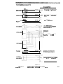
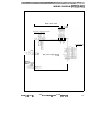
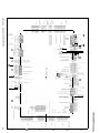
C. Inputs to DC Controller
Inputs to DC Controller
(1/4)
DCcontroller
PCB
I5311-7 t5v
<
-6 ’
LHP
Lens h o m e p o s i t i o n
sensor
Blank s h u t t e r h o m e
- 2
1
-
92
5 v
.
& SBHP
1
Pre-registration
paper sensor
W h e n lens is a t h o m e p o s i t i o n , ‘ 1 ’ .
(flag is a t Ql)
W h e n b l a n k s h u t t e r is at home position,
‘1’.
(llag at 02)
W h e n p a p e r is present. ‘1’.
(flag is a t cl3)
Scanner h o m e
p o s i t i o n se”sor
W h e n scanner is at h o m e p o s i t i o n . ‘ 1 ’ .
(llag at 04)
W h e n p a p e r is present. ‘0’.
(flag is not a t 05)
c a s s e t t e 1 paper
sensor
W h e n p a p e r is a b s e n t in “pper cassette, ‘0’.
(flag is not a t c)7)
C a s s e t t e 2 paper
sensor
W h e n papa is a b s e n t in lower c a s s e t t e . ‘0’.
(flag is not a t Q7)
5318-9
1”’
^ <t5v
M a n u a l f e e d papel
sensor
W h e n copy p a p e r is p r e s e n t , ‘1’.
(flag is a t 03)
r
I
Black tener level l
se”sor
I
I
I
W h e n b l a c k tener in b l a c k d e v e l o p i n g
a s s e m b l y is below specified value, ‘0’.
W h e n c o l o r d e v e l o p i n g a s s e m b l y is s e t .
‘1’.
L
C o p y b o a r d cover
switch 1
0
’
5306-9
’
.+ CBCCl
1
W h e n c o p y b o a r d cover is m o v e d down to
about 2 0 d e g . , ‘ 0 ’ .
(staris 1 st document identification)
5306X0! CBC,-~
- 1 1I
W h e n c o p y b o a r d cover is m o v e d down to
about5 d e g . , ‘ 0 ’ .
(starts 2 n d Qcument identification; about
1 sec thereafter)
-8
I
s w 4
C o p y b a a r d cover
switch 2
I
0
Figure 3-3
3-4
COPYRIGHT 0 1992 CANON I N C .
C A N O N NP2f2012020 R N . 0 M A Y 1990 PAINTEO I N JAPAN IIMPAIME AU JAPON)
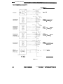
Inputs to DC Controller
(2/4)
DCcontroller PC8
sw6
wire cleaner nome
position switch
5309-3
1
0
,
sw9
5309-5
I
wfre clearw rear
position switch
0
‘W,CHP
-4
-6
,
w h e n transfer c o r o n a wire cleaner is a t
h o m e p o s i t i o n (front), ‘0’.
I
I
eWCRP
’
w h e n transfer c o r o n a wire cfeaner is a t
rear, ‘0’.
4
SIN7
5318-10
Q RDC
- 1 1 ’
Righ! door switch
Wh?n right door is opa, ‘1’.
W h e n paper is present, ‘1’.
( w h e n permanent magnet on papa
detection lever is away)
Delivery sensor
Clock signa1
Cfock signa1
Cassette 2 size
identification
l
Reads the c a s s e t t e size; see p . 3 - 4 3 .
c a s s e t t e 1 size
identification
I
1
I
TH
Thermistor
\
J
5313-9
+TH
I
Copy density
Voltage fowers w h e n fixing rolfer
temperahlre rises; analog signal.
Scanning lamp intensity varies; corrects
d e n s i t y if copy d e n s i t y is toa dark or light.
correction ,ever
Figure 3-4
COPYRIGHT 0 1592 C A N O N I H C .
CANON NPZf20/2MO RN.0 M A Y 1590 PRIIITED IH J A P A N ( I M P R I M E AU JAPOfff
3-5
5!Z#
OPERATIONSANDTIMING
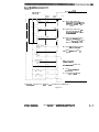
Inputs to DC Controller
(314)
-
D C controller P C B
-
W h e n ‘o’, L E D O goes ON: w h e n
d o c u m e n t is p r e s e n t , ‘0’.
(output)
W h e n ‘ 0 ’ , L E D O goes ON; w h e n
d o c u m e n t is p r e s e n t , ‘0’.
(output)
W h e n ‘o’, L E D O goes ON; w h e n
d o c u m e n t is p r e s e n t , ‘0’.
(output)
W h e n ‘0’. L E D O goes ON: when
d o c u m e n t is present, $0’.
W h e n S S R is ON, ‘1’
To P . 3-3
Figure 3-5
3-6
COPYAIGHT 8 1Y32 CANOH ING.
C A N O N HPZtZO/ZMO REY.1 O E C . 1992 PAINTEO IH JAPAN IIMPAIME AU JAPONI
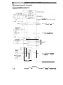
Inputs to DC Controller
(4/4)
DCcontroller PCS
Adjusting P C B
f - - - - - - - - - - - - - 1
1
1551
5312
-12
5 v
I
r
l-2
- 1 1 1
I
l
I
1-3
j
-10
I
I
I
I
1-4
I
I
I
I
- 9
VR5: adjusts image leading edge
registration (turn c l o c k w i s e to delay
registration clutch ON timing for
larger margin).
-a
V R 3 : a d j u s t s i m a g e l e a d i n g e d g e nonf m a g e w f d t h (turn clockwise to
delay grid bias ON timing for larger
non-image width).
<
V R 4 : a d j u s t s p a g e separation 2 n d p a g e
l e a d i n g e d g e n o n - f m a g e w i d t h (tun
c l o c k w i s e to delay glrd bias ON
timing for larger non-image width).
i
I
V R 2 : a d j u s t s AE slope (in service m o d e ) .
VRl: a d j u s t s AE referente p o i n t (in
service m o d e ) .
SWl: service switch
RI :
wl?en cut, AE r e m o v e d f r o m
standard mode.
R2:
w h e n cut. document size
identiflcation d i s a b l e d .
R3:
w h e n cut, a u t o clear d i s a b l e d .
For details on adjustment for each VR, see the SERVICE HANDBOOK.
Figure 3-6
COPYRIGNT 0 1992 CAHON IHC.
C A N O N NPZf20/2MO R E Y . 0 MAY 1990 PAINTEO I N JAPAN IIMPAIME AU JAPON)
3-7
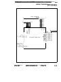
D. Outputs from DC Controller
Outputs from DC Controller
(113)
D C conuoller P C B
W h e n ‘ 0 ’ , RLI goes O F F : sae p . 3 . 4 7 .
W h e n ‘i’, fixing heater goes ON.
ming l a m p
See D. 3-26.
Main m o t o r
When ‘70’. main motor and scanner
c o o l i n g fan go ON.
Scanner cooling fan
D C power supply P C B
Figure 3-7
3-8
COPYAIGHT G 1592 C A N O N ING.
C A N O N NPZf20/2020 AN.I O E C . 1992 PAINTEO I N JAPAN IIMPRIME AU JAPONI d
OPERATIONS AND TIMING
Outputs from DC Controller
(2/3)
D C controller P C B
.__
F e e d e r roller
clutch 1
W h e n ‘0’. C L 1 goes ON.
k’h?n ‘ 0 ’ , C L 2 goes ON.
When ‘ 0 ’ . C L 3 goes ON.
Multifeeder clutch
( N P 2 1 2 0 only)
W h e n ‘0’. C L 4 goes ON.
C a s s e t t e 1 pi&up
clutch solenoid
W h e n ‘ 0 ’ , SLI goes ON.
c a s s e t t e 2 pick-up
clutch solenoid
W h e n ‘0’. SLZ goes ON.
Oil application
solenoid
W h e n ‘0’. S L 3 goes ON.
Blank switch
solenoid
W h e n ‘0’. S L 4 goes ON.
Multifeeder solenoid
(NP2120 only)
5355-3 ,++24v
1
W h e n ‘U, S L 5 goes ON
SL5
-4 ‘mi7
F e e d e r fan
W h e n ‘o’, F M 2 goes ON.
Exhaust fan
W h e n ‘ 0 ’ , F M 3 goes ON.
W h e n ‘ O ’ , p r e - e x p o s u r e l a m p goes ON.
pre-exposure l a m p
Figure 3-8
COPYRIGHT @ 1932 C A N O N ING.
C A N O N NPZl20/ZMO RN.1 DEC. 1592 PAINTEO I N J A P A N IIMPRIME AU JAPON]
3-9
8% O P E R A T I O N S A N D T I M I N G
Outputs from DC Controller
(3/3)
D C controller
M o t o r driver P C S
!
S e e p 3-18.
See p . 3-l 7
Cleaning
motor
See p. 3.38.
W h e n ‘0’. t o t a l copy counter goes ON
,“35y
J505-1 i
55047 -2 ’
C o n t r o l Card V
c
r
c
v
;
2
i
W h e n ‘0’. multifeeder
present L E D goes ON.
( N P 2 1 2 0 only)
-
- 4 I Con1rol
plel
PCS
-II
W h e n ‘0’. ON.
-14lp
-3
, “
I
3 J31k7CCmT
-
I
W h e n ‘0’. card present.
i 7JJ
Figure 3-9
3-l 0
cOPYRIGHT 0 1992 CANON INC.
C A N O N NPZl20/2MO RN.2 DEC. 1992 PAlNITO IN JAPAN [IMPRIME AU JAPONI
OPERATIONS AND TIMINGN
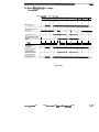
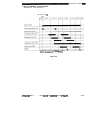
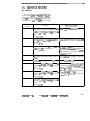
E. Basic Sequence
165W329’F
17OW338”F
N o t e : V a l u e in p a r e n t h e s e s indicatetemperature
w h e n C T unit is in “ s e .
Figure 3-10
Period
Description
Remarks
WMUP
(warm-up)
Between when the power is Waits until the fixing roller The warm-up time varies
switched ON and when the is heated.
depending on the fixing
fixing roller is heated lo 165’0
roller temperature.
329”F(145”C/293”F).
WMUPR
(warm-up
rotation)
Between when the fixing roller Stabilizes the fixing roller
is heated to 165%/329”F temperature.
(145”C/293”F) and to 17O”C/
338°F (150°C/3020F).
INTR (initial
rotation)
Between when the COPY Stabilizes the drum
START key is pressed and sensitivityinpreparationfor
when the scanner starts to copyoperation.
move forward.
AER (AE
measurement)
Between when the scanner is Measuresthedensityofthe Theoperationappliestothe
moved forward about 70 mm/ document by moving the the AE mode only.
2.8 in from the document scanner about 70 mm/2.8
leading edge and when it is in forward and in reverse.
returned to the home position.
SCFW (scanner While the scanner is moving
forward.
forward)
- The length of forward travel
varies according to the cas
sette size and reproduction
ratio.
* The speed of forward travel
varies according to the
reproduction ratio.
The scanning lamp illumi- The registration signa1 is
nates the document, and generatedtomovethecopy
paper to the transfer unit.
thereflectedlightisdirected
onto the photosensitive
drum by way of mirrors and
lens.
Note: Values in parentheses indicate the temperature when the CT unit is in use
Table 3-la
COPYRIGHT 0 1992 C A N O N I N C .
C A N O N NPZlZO/ZMO R N . 0 MAY 1990 PAINTIO I N J A P A N IIMPAIME A,, JAPON,
3-11
Description
Period
SCRV (scanner
in reverse)
Whilethescanner is moving in
reverse.
Returns the scanner to the
home position in preparation for the next copy.
LSTR
(last rotation)
FromwhenSCRViscompleted
until the main motorstops after
thecopypaperhasmovedpast
the delivery sensor.
Cleans the drum surface
electrostatically.
STBY (standby)
FromwhenLSTRiscompleted Waits for a press on the
until theCOPY STARTkey is COPY START key or
pressed or power is switched operation keys.
OFF.
3-12
COPYAIGHT 0 1992 CANON IX.
Remarks
The last copy is delivered.
CAWOW HPZl2012CQ0 AN. MAY 1 9 9 0 PAIHTFII I A J A P A N ( I M P R I M E AU JAPONI
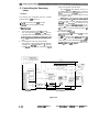
A. Varying the Reproduction
Ratio
The reproduction ratio across the drum (axial) is
varied by the lens drive system and that around the
drum(circumferential), bythescannerdrivesystem.
The lens drive system contains a zoom lens and,
as shown in Figure 3-11, the position of the lens and
the focal distance are shifted to vary the reproduction ratio across the drum.
ThescannerdrivesystemmovestheNo.1
mirror
faster in relation to the drum rotation for reduced
copies or slower for enlarged copies.
Note:
DIRECT -?FREDUCE B
ENLARGE m&
Figure 3-11
When in the DIRECT mode, the speed of the
No. 1 mirror and that of the drum rotation are
identical.
COPYRIGHT 0 1992 CARON IHC.
C A N O N NPZlZO/ZMO R N . 0 MAY 1990 PAIRTEC I N JAPAN [ I M P R I M E AU JAPOIII
3-13
OPERATIONS AND TIMING
B. Lens Drive System
1. Outline
The lens unit is driven by the lens drive motor
(M3).
The lens drive motor also serves to move the
blank exposure shutter and is switched by the blank
shutter solenoid (SL4); see p. 3-37. When the blank
shutter solenoid (SL4) goes ON, the drive is transmitted to the lens drive pulley to move the lens unit.
WhenthepowerisswitchedON, SL4goesON to
rotate the lens drive motor, thereby moving the lens
to the home position. When the lens reaches the
home position, the lens drive motor rotates in reverse; it then stops after the signa1 plate has left the
sensor (Qi) and a specific number of pulses has
been generated, positioning the lens at the DIRECT
position.
Likewise, the lens is first moved to the home position also for both enlargement and reduction operations; it is then moved and positioned at a point
suited to the specified reproduction ratio.
Lens drive motor
B l a n k shuner
mIM3)
Blank shutter d
Figure 3-12
3-l 4
COPYAIGHT 0 1592 C A N O N IHC.
C A N O N NPZl20/2MO REY.0 M A Y 1590 PRINTEO I N JAPAN IIMPAIME AU JAPONI
OPERATIONS AND TIMINGM
B l a n k shutter
solenoid (SL4) \
Lens drive m o t o r
r
-
l
Lens drive pulley
B l a n k shutter drive
ENLARGEMENT
Figure 3-13 Lens Drive System (viewed from above)
COPYAIGHT 0 1992 CANON IWC.
C A H O H HPZlZO/ZMO KV.0 M A Y 1590 PRIHIEO I N JAPAN IIMPAIME AU JAPOHI
3-15
OPERATIONS ANDTIMING
2. Basic Sequence for Lens Drive System (reduction)
C O P Y S T A R T k e y ON
P O W E R s w i t c h ON
’ WMUP ‘P==F
DIRECT
Lens drive m o t o r ( M 3 )
I
I
t
B l a n k shulter solenoid ( S L 4 )
c
Lens h o m e position s e n s o r (Qí)
L
Blank shutter home position sensor
w
Figure 3-14
@ Sets the lens at the DIRECT position.
0 Sets the blank shutter at the home position.
@ Sets the lens at a point suited to the specified
reproduction ratio.
@ Moves the blank exposure shutter for blank
exposure (rear) to suit the specified reduction
ratio.
3-16
COPYAIGHT Q 1932 C A N O N IHC.
The copier’s blank exposure shutter is designed to
move according to the specified copy size; as such,
the shutter moves also in the DIRECT mode.
C A N O N NPZ,ZO/ZMO R N . 0 M A Y 1590 PAIHTEO I N JAPAH IIMPRIME AU JAPONI
O P E R A T I O N S ANO TIMING RSSZ
3. Lens Drive Motor Circuit
The lens drive motor is a stepping motor and
rotatesin responsetothedrivepowersignal(LNSTB)
and pulse signals (LNA. LNA, LNB, LNB).
5308
Tostartthelensdrivemotor, LNSTBgoes’l’; and
the motor is rotated by applying pulses on each
phase in sequence.
When the lens drive motor is at rest, LNSTB is ‘0’;
the motor is supplied with current by way of R418 so
as to hold the lens in place.
5 4 0 1 ! ,k i”“‘” 1
-1
-12
LNA
B
I
I
1
-3’
Lens drive m o t o r
~.
D C controller P C B
M o t o r driver P C B
Figure 3-15
COPYRIGHT 0 1992 C A N O N I H C .
C A N O N HPZ120/ZMO R N . 0 MAY 1990 PAINTEO I N JAPAN IIMPRIME AU JAPOHI
3-17
C. Scanner Drive System
1. Outline
Thescannerisdrivenbythescannermotor(M2).
The scanner motor changes its direction of rotation
to move the scanner forward and in reverse. When
the scanner moves forward, the motor speed is
changed to suit the specified reproduction ratio;
when the scanner mover in reverse, however, its
speed is constant regardless of the reproduction
ratio (3.5 times as fast as when moving forward).
The distance over which the scanner moves
varies according to the length of the copy paper and
the reproduction ratio.
No. 2 mirror mount
Scanner home
N o . 1 m i r r o r mount
D C controller PCE
M o t o r driver P C B
n
Scanner motor
drive signa1
Figure 3-16
3-l 8
COPYAIGHT 0 1992 C A N O N I N C .
C A N O N NP2Wl12MO R N . 0 M A Y 1990 PAINTEO I N JAPAN IIMPAIME AU JAPONI
2. Relationship Between Sensor and Signals
Scanner
Scanner sensor
Signa1
Description
Forward
Scanner home
position
SCHP
In reverse
- Registration clutch ON
- Grid high voltage output ON
-L
* Scanner reverse OFF (0.1 sec later)
Table 3-2
3. Basic Sequence for Scanner (ENLARGE/REDUCE)
POWER switch ON
COPY START key ON
COPY START key ON
Figure 3-17
COPYRIGNT @ 1992 C A N O N ING.
C A N O N NPZl20/2CQO AB.0 M A Y 1590 PAINTEO I N JAPAN IIMPRIME AU JAPON,
3-19
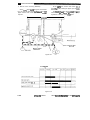
4. fblovement of Scanner in Page Separation Mode (2 documents)
Documentleading
Documentleading
e d g e o f Istpage
e d g e o f istpage
Documentleading
Documentleading
e d g e o f Istpage
edgeof Istpage Documentleading
Documentleading
Forward.i-kForward i--i-Fo¡ward+-&Fonvard&=
Reverse
Reverse
Reverse
Figure 3-18
1, ll, and III shown in Figure 3-18 are controlled with
referente to the document leading edge (falling
edge of 04) of the first page.
1:
The distance over which the scanner moves
from the document leading edge is determined
by the reproduction ratio and cassette size as in
the normal copy mode.
II: It is more or less identical to 1; however, if the
distance over which the scanner moves forward
is longer than 210 mm/8.3 in (115/220/24OV
models), 210 mmB.3 in (216 mm/85 in) will be
identifiedas thereferencetothedocument leading edge.
Ifthedistanceisshorterthan2lOmm/8.3in(216
mm18.5 in), the point at which the scanner reverses will be identified as the document leading
edge of the second page.
III: Same as 1.
3-20
COPYAIGNT 0 1992 C A N O N ING.
Note:
The distance over which the scanner moves
cannot exceed 432 mm/1 7 in from the document leading edge (the point reached by the
scanner having moved forward 10 mm/0.4 in
from the falling edge of Q4); further, the distance is limited by the specified reproduction
ratio.
In the case of enlargement by 200%, the
distance is 216 mm18.5 in max.
C A N O N NPZlZO/ZMO RN.0 MAT 1590 PAINTEO I N J A P A N IIMPRIME AU JAPONI
OPERATIONS AND TIMING m
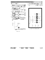
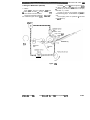
D. Document Sìze Identification
1. Outline
The copier is equipped with auto paper selection
and auto reproduction ratio selection mechanisms.
These mechanisms call for identification of the
document size as described below.
To enable such identification, three circuits are
attached under the copyboard glass (Figure 3-21);
when the copyboard cover is lowered, the DC controller checks the output of these circuits twice,
thereby identifying the document as Ledger, Legal,
Letter, or Mini.
The document identification circuit causes its
LED to emit light to illuminate the document; the reflected light is then checked by the phototransistor,
whose output is sent to the DC controller.
2. Mechanism
The DC controller checks the output of the document identification circuit when the copyboard cover
is lowered to about 20 deg. (SW4 ON) and about 1
sec second afterthe over has been lowered to about
5 deg. (SW5 ON).
The DC controller recognized the presente of a
document if the two measurements are identical:
conversely, it recognizes the absence of a document
if the measurements are different.
C o p y b o a r d cow?
[1
DCcontroller
PCB
D C conlroller P C B
/
(The thickness of the arrows represents the degree of the level.)
Figure 3-19
When a document is present, the light reflected
by the document is checked by the document identification circuit; therefore, the output of the circuit is
constant regardless of the angle of the copyboard
cover.
When no document is present, the output of the
circuit from the first measurement is low or none at
COPYRIGHT 8 1992 CANON INC.
all;theoutputofthecircuitfromthesecondmeasurement, on the other hand, is high because the light is
reflected by the document sheet.
If the document is too thick and, therefore, if only
SW4goesON. thedocument sizeis identified based
on the output level of this time.
C A N O N NP2120/2070 R N . 0 MAY 1590 PRINTEO I N JAPAN IIMPRIME AU JAPON]
3-21
OPERATIONSANDTIMING
C o p y b o a r d cover
m o v e d down
C o p y b o a r d cover
m o v e d up
77
r Y
C o p y b o a r d cover switch 1 (SW4)
C o p y b o a r d cover switch 2 (SW5)
ON
-
ON
-
200
0
I
I
I
l
! D C controller identilies
I the dacument size
1
I
I
I
OFF
1 OFF
50
Tl
I
Document identification timing
D o c u m e n t i d e n t i f i c a t i o n circuit L E D
Figure 3-20 Document Identification Timing
3-22
COPIAIGHT 0 1992 C A N O N ING.
C A N O N NP2120/2020 KV.0 M A Y 1990 PRINTEO IN JAPAN ( I M P R I M E AU JAPONI
OPERATIONS AND TIMING
11
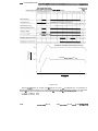
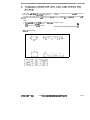
3. Identification of Document Size
Document identification circuit
The DC controller identifies the size of documents based on the levels of the output from the
document identification circuit; see Table 3-3.
121 Ix4 I constant ) vatying ) constant 1
A4
3
I
constant:
varying:
I
constant constant varying
I
I
varying
constant varying
=l= 4
vafying
varying
constant
varying
varying
vafying
no change to output of document identification circuit; recognizes resence of
document.
change to output of document identification circuit; recognizes absence of document.
Table 3-3
v
- - - Dccument i d e n t i f i c a t i o n cir
rr
p
Document identification circuit t
’
-l-&
__~
D o c u m e n t identificatlon signa1 1 (DSZl)
D c c u m e n t identification
signa1 0 ( D S Z O )
D c c u m e n t Identilication signa1 2 ( D S Z 2 )
t
I
1
D C conlroller PC6
Copybard MVW signa1 2 (CSCC2)
Figure 3-21
CUPVAIGHT 0 1992 C A N O N ING.
C A N O N NPZl20/2MO RN.0 MAV 1990 PRINTEO I N J A P A N IIMPRIME AU JAPONI d
3-23
OPERATIONS AND TIMING
- Controls the scanning lamp.
- Controls the primary/transfer coronacurrent and
grid bias voltage.
- Controls the developing bias.
- Measures the document density.
- Controls the developing assembly and drum
cleaning unit.
- Controls the blank shutter.
A. Outline
Figure 3-22 shows the construction of the image
formation system, and the system has the following
functions:
3
Pre-exposure lamp
AE senso,
I
l
-LAr,
Black d e v e l o p i n g I
assembly
I
L a m p regulator
-
/‘^‘\
x
w
a
5
c:
‘.
\
Developing
cylinder
Photosensitive drum
I
I
GRDON
r
High-voltage transformer
Figure 3-22
3-24
COPVNIGNT 0 1992 C A N O N I N C .
C A N O N NPZl20/2MO MEV.0 MAV 1990 PAINIEO IN JAPAN IIMPRIME AU JAPONI
OPERATIONS AND TIMING
B. Basic Sequence of Image
Formation
P O W E R switch ON
C O P Y S T A R T kev
PtimaryITransfercorona
unit
G r i d tias
I
I
l
I
1-1
J
I
I
I
Figure 3-23
COPVRIGHT 0 1992 CANON I N C .
C A N O N NPZl20/2MO RN.0 M A V 1930 PAINTEO IN JAPAN IIMPAIME AU J A P O N I
3-25
C. Controlling the Scanning
Lamp
1. Outline
The scanning lamp iscontrolled bythe DC controller
PCB as follows; see Figure 3-24.
- Turns the scanning lamp ON and OFF.
* Controls the scanning lamp intensity.
2. ivlechanism
a.
Turning the Scanning Lamp ON and OFF
The microprocessor (slave; Q302) on the DC
controller PCB causes the transistor (Q324) to
goON,therebycausingthescanninglamp(LAl)
to go ON; the lamp goes OFF when Q324 goes
OFF.
b. Controlling the Scanning Lamp Intensity
The intensity of the scanning lamp is varied by
controlling the voltage supplied to it in response
to the level of the intensity adjustment signa1
(LINT) from the DC controller PCB.
The LINT signa1 varies between 10 and 16 V
as determined by the copy density correction
lever, controlling the voltage supplied to the
scanning lamp so that it varies between 50 and
75 V (phase control).
WhentheCTunitisused,thevoltageapplied
to the scanning lamp is raised by about 1.8 V as
opposed to when the black developing assembly
is used so as to increase the intensity of the
scanning lamp. A constant voltage (70 V),
however, is applied to the scanning lamp during
AE exposure for both the black developing assembly and CT unit.
c. Error Identification Circuit
The scanning lamp is monitored using the lamp
ON signa1 (LIGHT).
lf the scanning lamp ON signa1 (LIGHT) is
present on the DC controller for about 20 sec
continuously, the error identification signa1 generates the AC power OFF signa1 (ACOFF) to cut
off the AC power; see p. 3-47.
i
T
Scanning
lamp
(LAI)
-2 LMPOr\!
-5
-5 ZXDP
-2
circuit
Switching
- circuit
Lamp reg&tor
D C wntroller P G B
Figure 3-24
3-26
COPVRIGHT 0 1992 CANON INC.
C A N O N NPZl20/2MO RN.0 M A V 1990 PAINTEU IN JAPAN IIMPAIME AU JAPONI
Theerrordetectioncircuit alsogoesONwhenthe
thermal fuse (Ful) or the scanning lamp blows,
causing the relay (RLI) togo OFFandcuttingthe AC
power.
The above condition prevents generation of the
zero-cross and causes ‘E221’ to be indicated on the
control panel.
3. Copy Density Correction Lever
The copy density correction lever serves to prevent foggy images caused by deterioration of the
photosensitive drum. The copy density correction
lever changes the intensity of the scanning lamp,
and a higher frees the copies of fogging.
CV)
75 --- ,
a
P
34
%
2
E
: 50 IY
---t
-----
--_-----_,
t
I
I
t
I
,
I
16
10
(VI
L I N T signa1
(Setbycopydensitycorrection
lever.)
Figure 3-26
Figure 3-25 Copy Density Correction Lever
COPYAIGNl CC 1992 C A N O N I N C .
C A N O N NPZlM/2DZO RN.1 JAN. l!Z!'2 PRIIITfD IN JAPRN [ I M P R I M E AU JAPOHI
3-27
WI¶ O P E R A T I O N S A N D T I M I N G
D. Controlling the Primary/
Transfer Corona Current and
the Grid Bías Voltage
1. Outline
Figure 3-27 shows the circuii which controls the
current for the primary/transfer corona unit and the
voltage level of the grid bias; it has the following
functions:
@ Turns the primaryltransfer corona current ON
and OFF;
@ Controlstheprimary/transfercoronacurrenttoa
constan! value;
@ Switches the grid bias voltage level of the primary corona unit.
@ Controls the grid bias voltage of the primary
corona unit.
Theoutputtotheprimarycoronaunit iscontrolled
toa constant value; the shield current is controlled to
eliminate the effects of environmental changes on
the corona discharge.
The primary corona current and transfercorona
current are turned ON and OFF by the high-voltage
output signa1 (HVTON).
The grid bias voltage level is switched by the grid
bias control signa1 (GRDON).
D C controller P C S
r
1
2. Turning the PrimaryiTransfer
Current ON and OFF
Corona
@ When HVTON = 1,
bdifferential amplifier circuit goes OFF.
4variablepulsegeneratorcircuitgoesOFF.
bHigh-voltage transformer goes OFF.
0 When HVTON = 0,
bdifferential amplifier circuit goes ON.
bvariablepulse generatorcircuit goes ON.
b High-voltage transformer goes ON.
3. Controlling the Primary/Transfer
Current Constant
Corona
If a corona current larger than the specific value
flows from the primary corona unit because of
changes in the environment. the level of the feedbacksignal totheifferentialamplifiercircuit increases
andtheoutputofthecircuitdecreaseqthecondition
in turn decreases the corona current from the primaryltransfer corona unit, thereby controlling the
current to a specific value.
If an over-current flows on the output side of the
high-voltage transformer used for primary/corona
unit, the limit control mechanism is activated to keep
the flow to a specific value.
High-voltage transler ( H V T )
7.
Primary c o r o n a unit
Figure 3-27
3-28
COPYRIGNT 0 1992 C A N O N ING.
C A N O N NPZ12O/ZMO REY.0 M A Y 1990 PRINIKI I N JAPAN IIMPRIME AU JAPONI
4. Turning the Grid Bias ON and OFF
@) When the image is exposed, the DC controller
9=“,““,=,.
%7goesON; nooutputfromthecomparator circuit.
bQ6 goes OFF.
bcurrent flows into the transformer
(14); 05 goes OFF.
“~í;;“B”,ha,;“.
@ When the image is not exposed, the DC controller generates GRDON=l.
ka7 goes OFF; output from the comparator
circuit.
bQ6 goes ON.
L*current does not flow into the transformer (T4).
bgrid bias is not applied.
The above condition does not charge the drum
and, as such, toner is not attracted to the photosensilive drum (blank control).
The voltage applied to the grid is returned to the
comparator circuit. thereby providing a constant
voltage.
COPYAIGHT G 1992 C A N O N I N C .
C A N O N NPZi20/2MO R N . 0 M A Y 1990 PAINTEO IN JAPAN [ I M P R I M E AU JAPONI
3-29
E. Controlling the Development
Bias
2. Mechanism
a. Tuming the Development Bias AC Component
ON and OFF
1. Outline
Figure 3-28 shows the circuit that controls the
development bias and has the following functions:
0 Tums the development bias AC component ON
and OFF.
Q Controls the development bias DC component
voltage level.
The copier varies the voltage level of the developmentbiastocontrolthecopydensityaccordingtothe
settings of the following:
- Copy density key position
- AE sensor output
- Developing assembly type
When the black developing assembly is set. J24-1
and -4 are shorted by means of a jumper wire,
thereby identifying the presente of the assembly.
3-30
COPYAIGHT 0 1992 CANON ING.
The square wave osciilatorcircuit is at work at all
times as long as power is present.
@ When ACBON=l,
4AC bias switch circuit goes ON.
bsquare wave oscillator circuit output is
cut.
The above condition deprives the developing
cylinder of AC biases.
Q When ACBON=O,
bAC bias switch circuit goes OFF.
The above condition causes the AC bias switch
circuit to go OFF; as such, the output of the
square wave oscillator is sent to the Tl drive
circuit. raised lo 1300 VAC, and is supplied lo the
developing cylinder. The output of the AC highvoltage transformer, on the other hand, is rectified by the rectifier circuit and supplied to the
static eliminator (about 3.2 KV).
C A N O N NP2lZO/ZGZO RN.0 MAY 1990 PNINTED I N J A R N I M P R I M E AU JAPONI
OPERATIONS ANDTIMING B
b.
The above condition supplies the developing
cylinder with DC biases.
DCBC varies between 6 and 16 Vas adiusted
by the copy density key.
Controlling the DC Bias Voltage Level
Fioure 3-28 shows the differential amplifier circuit, which operates when DCBC is 16 V or less.
Controlling the DC Bias Voltage Level
DCBCis6to16V.
bdifferential amplifier circuit goes ON.
bvariable pulse generator goes ON.
hDC high-voltagetransformergoesON.
I
DCBC
Development bias
DC component
(black developing
assembly)
Developing bias
DC component
(CT unit)
D C controller
r---
I
6to16V
450 to 430 v
480 to-110 V
High-voltage transformer (HVT)
C T unit is used.
Figure 3-28
COPYRIGNT 0 1992 C A N O N ING.
C A N O N NPZWl/2MO KV.0 M A Y 1990 PNINTEO I N J A P A N IIMPAIME AU JAPONI
3-31
mOPERATIONS ANDTIMING
3. Control Sequence for Development Bias
C O P Y S T A R T k e y ON
ST
\\hlLP
B 1 -, ó‘
i\IlLPR
’
IhTR
SCF\\
SCRT
SCF\\'
SCR\I
LSTH
S'I'UY
Grid bias
Figure 3-29
@ The levels of the development bias DC component control signa1 and DC bias vafy according to the copy
density key and AE sensor output.
The level of the DC bias during image exposure varies according to the type of developing assembly.
@ The level of the DC bias varies according to the type of developing assembly; other than during image
exposure.
. black developing assembly -320 V (approx.)
. CT unit _,___._.__._________......................... -220 V (approx.)
Note:
The development bias AC component when the CT tmit is used is synchronized to the main motor
3-32
COPYRIGHI 0 1992 CANON ING.
C A N O N NP2,20/2MO NEV.0 MAY 1930 PRINTEO I N J A P A N IIMPNIME AU JAPON)
F. Measuring the Document
Density
1. Outline
The copier has an automatic exposure (AE)
mechanism, which controls the DC component of
the development bias according to the density of the
document. If the document is uniform in density, the
AE mechanism varies the DC omponent of the
development bias to enable reproduction of fog-free
copies.
NOTE:A
represen& AE s e n s o r positmn.
(approx.)(approx.)
Figure 3-30
2. Mechanism
3. Fteading the AE Sensor Output
The scanner is moved forward about 70 mm from
the image leading edge with the scanning lamp kept
ON; the AE sensor reads the document density, and
the output is sent to the DC controller.
Based on the output from the AE sensor, the DC
controller controls the DC component of the development bias.
The AE sensor consists of a photodiode (Q702)
and operation amplifier (Q701); when the light received by the photodiode (reflected by the document) is strong, the output voltage (AE) of the
operation amplifier is low; on the other hand, if the
The DC controller reads the output (AE) of the AE
sensor based on the zero-cross signa1 (ZXDP) sent
by the lamp regulator.
Thelimitercircuitconsistsof Q701 (2) anddiodes
and serves to cut AE output of 5 V or more to prevent
damage to the microprocessor (Q302).
IftheAEoutputfallsunderl.O,avoltageof 1 Vwill
be assumed; if the AE output rises above the setting
of VR2. it is lowered to maintain the setting.
__--_--_----- --- ---I
I
I
D C controller P C B
r---l
L-
-
-
AEsensor
- -
-
I
Adjusting P C B
Figure 3-31
COPYNIGHT @ 1592 CANON I N C .
C A N O N NPZt20/2020 NN. J A N . 1992 PRINTEO I N J A P A N IIMPRIME At, JAPON, d
3-33
~OPERATIONSAND T I M I N G
4 . Adjustment
The following adjustments should be made when
the AE sensor or adjustment PCB has been replaced; starl with adjustment of the AE referente
point and then AE slope, and make sure both adjustments are made without fail.
6) Adjust VR1 (AE ref.) on the adjusting PCB so
that the copy counter on the control panel indicates ‘20’.
@ Adjusting the AE Referente Point
1)
2)
3)
4)
5)
Remove the adjustment cover from the rear of
the left cover.
Switch the power ON.
* Wait untilthe WAITstate isoverand theCOPY
READY indicator is green.
Place an NB-3 Test Sheet or NA-2 Test Sheet,
and close the copyboard cover.
Press the push switch (SWI ; service switch) on
the adjusting PCB.
- ‘0’ will be indicated on the copy counter on the
control panel.
- If the indication is not’O’, enter’o’on the tenkey
pad on the control panel.
Press the SORT/GROUP key on the control
panel.
- The scanner moves forward to the AE measurement point, and the scanning lamp goes
ON.
Note:
The scanning lamp remains ON for about 8
sec; to turn it ON once again, press the SORT/
GROUP key, and press the key once gain
after the operation stops.
3-34
COPYRIGHT 0 1992 C A N O N ING.
TestSheet N e w s p a p e r
Figure 3-32
7)
Press the SORT/GROUP
justments.
key after making ad-
- The scanning lamp goes OFF, and the scanner returns to the home position.
“(2) AE slope adjustment” should be made
continuously.
AE adjustment can be completed by performing”(1) AE referencepoint adjustment” though
“(2) AE slope adjustment”.
CAHON ffP2l20/2020 AEV.I J A N . 1992 PRINTEO I N J A P A H IIMPAIME AU JAPONI
8)
@ Adjusting the AE Slope
1) Remove the Test Sheet, place a newspaper on
the copyboard, and close the copyboard cover.
2) Press the SORTIGROUP key on the control
panel.
* The copier operates as in step 5) of “Adjusting
the AE Referente Point.”
3) Take notes of the value shown on the copy
counter of the control panel.
4) Press the SORT/GROUP key on the control
panel.
- The copy counter on the control panel will
indicate ‘0’.
5) Enter ‘1’ on the tenkey pad on the control panel.
- The copy counter on the control panel will
indicate ‘1’.
6) Press the SORTIGROUP key.
7) Turn VR2 (AE slope) on the adjusting PCB so
that the value on the copy counter of the control
panel is the same as the value recorded in step
Press the SORT/GROUP key after making adjustments.
9) Press the push switch (SWI) on the adjusting
PCB
Blank
3)
Document denslty
Test S h e e t N e w s p a p e r
Figure 3-34 Adjusting PCB
Figure 3-33
COPYAIGHT @ 1992 CAllON I N C .
C A N O N NPZlZO/ZMO R N . 0 M A Y 1990 PRIHTEO I N J A P A H IIMPAIME AU JAPONI
3-35
m OPERATIONSANDTIMING
2. Monitoring
G. Developing Assembly and
Drum Cleaning Unit
1. Outline
The blade and developing cylinder inside the
drum cleaning unit are rotated by the drive from the
main motor.
The level of toner inside the black developing
assembly is monitored by the toner sensor (Q9):
and, whenthefevelfalls belowaspecifiedvalue, the
ADD TONER indicatoron the control panel starts to
flash.
The CT unit cannot be replenished with tener;
replace the CT unit as a whole when it runs out of
toner.
The toner collected by the cleaning blade is
stored inside the drum cleaning unit.
Thedevelopingassemblyisbrought intocontact
with the photosensitive drum together with the
developing assembly rail by the developing assembly release lever.
the Toner Level
A piezoelectric oscillator toner sensor (Q9) is
provided inside the black developing assembly to
monitor the level of toner.
Theoutputofthetonersensorremains’i’as
long
as a specific level of toner is inside the assembly;
whenthetonerdecreases belowthelevel,theoutput
goes ‘0’.
The DC controller reads the output signa1 for 5
sec aftercopy operation is over; if the signa1 remains
‘O’continuously, it recognizes ‘no toner 1’. When ‘no
toner 2’ is recognized, the DC controller flashes the
ADDTONERindicatorandprohibitscopyoperation.
The CT unit is not equipped with a toner level
detection mechanism, or the cleaning unit is not
equipped with a waste toner level detection mechanism.
3. Torque Limiter
If a large load is imposed on the photosensitive
drum while the drum is rotating forsome reason, the
torque limiter cuts off the drive from the main motor
to stop the rotation of the drum.
D r u m c l e a n i n g unit
G
DL”,
as*embly r
a
i
l
Figure 3-35
3-36
COPYAIGHT Q 1992 CANON INC.
C A N O N NPZl20/2MO RN.0 M A Y 1990 PRINTEO I N J A P A H IIMPRIME AU JAPONI
H. Blank Control
2. Controlling the Blank Exposure Shutter
1. Outline
The copier uses the light from the pre-exposure
lamp to black out the non-image section in the
REDUCE mode or section not in contact with the
drum in the DIRECT mode.
The blank exposure shutter serves to control the
area over which the light is directed.
The blank exposure shutter is operated by the
drivefrom the lens drive motor (M3) by way of gears
when the blank shutter solenoid (SL4) is OFF.
The lens drive motor first returns the blank exposure shutter to the home position (at Q2); it then
rotates in response to the drive pulses from the DC
controllersuitedtothereduction ratio, therebysliding
the blank exposure shutter.
To black out (white out) the non-image section
between two copies, the copier changes the potentialonthegrid biasoftheprimarycoronaunit instead
of using blank exposure; see p. 3-29.
To black out the non-image section for reduced
copies or section not in contact with the drum in the
DIRECT mode, the light of the pre-exposure lamp is
directed against the drum by way of the reflecting
plate, thereby preventing adhesion of toner on the
drum.
Blank shutter solenoid (SL4)
Lens d+/e motor (M3)
B l a n k s h u t t e r h o m e posifion s e n s o r (CIZ)
B l a n k e x p o s u r e shuner
Pre-exposure l a m p
Phofosensitive
drum
Figure 3-36
COPYAIGHT 0 1592 C A N O N ING.
C A N O N NP2120/2MO KV.0 M A Y 1990 PAINTEO I N J A P A N IIMPAIME AU JAPONI
3-37
m O P E R A T I O N S AND T I M I N G
1. Controlling the Transfer
Corona Wire Cleaning
Mechanism
2. Cleaning Niechanlsm
1. Outline
The copier has an automatic cleaning mechanism for the transfer corona wire; cleaning is executed when the power switch is turned ON or when
the fixing assembly is 1OO”C/212”F or below.
The wire cleaner is moved by the cleaner motor
(M4) back and forth once along the wire (about 20
sec).
When the wire cleaner mount moving folward by
M4 actuates the microswitch (SW9) located at the
rear of thetransfer rail, M4 rotates in reverse to move
the wire cleaner in reverse.
The wire cleaner stops when the wire cleaner
mount actuates the microswitch (SW6) located in
front of the transfer rail (home position). If SW6 is not
actuated, the COPY START key on the control panel
remains red for 90 sec even after the wait period is
over.
If the power is turned OFF in the middle of
cleaning operation, the wire cleaner mount stops
where it is. If the transfercorona assembly has been
dertached in this condition, attach it back to the
copier while holding the wire cleaner at the rear by
hand.
Cleaner m o t o r ( M
er c o r o n a unit
/
re c l e a n e r h o m e
sition s w i t c h ( S W 6 )
M o t o r driver P C S
D C controller PCS
Figure 3-37
3-38
COPYAIGNT & 1592 C A N O N ING.
C A N O N NPZl20/2MO AEV.I J A N , 1992 PRINTEO I N J A P A N IIMPRIME AU JAPONI
The control card, on the other hand, increases
the count in response to each pick-up.
The presente of paper in the upper and lower
cassettes is checked by photointerrupters (Q6, Q7);
if paper is absent, the cassette out signa1 (UPCPD,
LCPD)goes’O’andtheADDPAPERindicatoronthe
control panel starts to flash.
A. Outline
Figure 3-39 shows the basic construction of the
pick- up/feed system.
When the pick-up clutch solenoid (SLI or SL2)
goes ON while the main motor (MI) is rotating, the
drive of the main motor causes the pick-up roller to
rotate, thereby movingthe paperto feeder roller 1 or
2.
Afterhaving passedthroughthefeederroller,the
copy paper is moved by the registration roller so that
the leading edge of the image on the photosensitive
drum and that of the copy paper match; thereafter,
the paper is sent to thetransfer unit, separation unit,
feeder unit, fixing assembly, delivery unit, and to the
copy tray.
The path along which the copy paper moves is
provided with photointerrupters (Q3, Q5) servicing
as the pre- registration and separation sensors and
withacontactsensor*(SW8),asthedeliverysensor.
If the paper fails to reach or pass the sensors within
a specific period oftime, thecondition is identified as
a jam and the JAM indicator on the control panel
starts to flash.
The counter increases by one when the delivery
sensor (SW8) detects the trailing edge of the copy
paper.
COPYAIGNT 0 1992 C A N O N ING.
* The contact sensor used as the copier’s delivety
sensor (SW8) makes use of attraction of a permanent magnet to drive the reed switch.
The paper detection lever is equipped with a
permanent magnet and, when the magnet comes
into contact with the reed switch, the switch goes
OFF; the switch goes ON (paper resent) when
the magnet is off contact.
Figure 3-38 Contact Sensor
C A N O N NP212012MO RN.0 MAY 1930 PRINTEI IN JAPAN [IMPRIME AU JAPONI
3-39
OPERATIONS AND TIMING
DC controller PCB
*
,’
,
,
f
.
5
r
>
:
;c
:
>
1
2
>
>
Clubh
Figure 3-39
3-40
COPYAIGNT 8 1992 CANON ING.
CANON NPZl20/2020 RN.0 MAY 1990 PAINTEO IN JAPAN IIMPRIME AU JAPONI
OPERATIONS AND TIMING
2. Sequence for Pick-up/Feed System
COPY START key ON
ON
. Control Card V, if attached, ,ncreases the coun, when
the pick-up clutch solenoid (SLI, SLZ) goes ON.
Figure 3-40
COPYAIGNT 0 1992 CANON INC.
CANON NPZ120/2MO REY.0 MAY 1990 PAINTED IN JAPAN IIMPRIME AU JAPONI
3-41
m OPERATIONSANDTIMING
3. Manual Feed Pick-Up (NP2020)
When copy paper is slid along the manual feed
tray, the manual feed sensor (Qf3) detects the copy
paper and the main motor (Mi) starts to rotate in
response.
At the same time, feeder roller clutch 1 (CLI)
goes ON, thereby feeding the paper up to the registration roller.
The sequence used to feed the copy paper in the
manual mode is the same as in feeding A3 paper
regardless of the size of the copy paper.
DC confroller PCB
Manual feed pi&up roller
Registration roller
Figure 3-41
copy papes set
Feeder roller clutch 1 (CLl)
Figure 3-42
3-42
COPYAIGHT Q 1992 CANON INC.
CANON NPZl20/ZMO AEV.0 MAY 1990 PAINTEO IN JAPAN IIMPRIME AU JAPONI
OPERATIONS AND TIMING
4. Using the Multifeeder (NP2120)
a. Outline
When you are using the multifeeder, copy paper
is picked up from the stack on the tray. This way, you
can feed sheets one after another.
Thepresenceofastackonthetrayis detected by
the multifeeder paper sensor (Q8).
The stack on the tray is pushed against the pickup roller by the paper guide plate. The pick-up roller
is rotated by the drive from the main motor (Mi)
transmitted by clutches.
The pick-up roller and the separation pad pick up
onesheetofcopypaper, andsendittothe registration
roller.
The foregoing series of operations is executed
for each pick-up.
Main motor
Multifeeder sensor
Papa sensor lever
Phok
Figure 3-39a
COPYRIGNT & 1932 CANON ING.
CANON NPZ120/2MO RN.0 DEC. 1592 PAINTEO IN JAPAN [IMPRIME AU JAPON)
3-42a
m OPERATIONS AND TIMING
b. Sequence of Operations (pick-up from multifeeder)
COPY START key
ON
Figure 3-39b
3-42b
CWf’flIGHT 0 1992 CANON ING.
CANON NPZl20/2020 RN.0 OEC. 1992 PRINTEO IN JAPAN IIMPRIME AU JAPONI
OPERATIONS AND TIMING m
B. Identifying the Cassette Size
Based on the combinations of the switches which
have been actuated, the microprocessor recognizes
the presence/absence of a cassette as shown in
Table 3-4 and, at the same time, determines where
to reverse the scanner and how to control the blank
shutter.
The presence/absence of a cassette in the cassette holderand thesize thereof are identified byfour
switches (CSTI through CST4) provided in each
cassette holder.
x
0: SW is OFF.
1: SWisON.
(right)
No cassette
Note:
ULI : Argentine-LTR
Govemment-LTR
Korean Govemment
ULZ: Argentine-LGL
Govemment-LGL
Argeniine-LTR-R
Govemment-LTR-R
Foolscap
Folio
Australian Foolscap
Korean Government-R
OFICIO
Equadoran OFICIO
Bolivian O F C I O
u2
(See Note.)
A4
(210X297)
B5R
1257X182)
B4
(364X257)
A4R
(297X21 0)
A3
(420X297)
Ul
(See Note.)
Ul
(See Note.)
u2
(See Note.)
Letter 8.5”Xll”
:216X279)
Mini 5 5”X8.5”
:216X;403
III Io
-egal 8.5”X14”
:356X21 6)
1
1
-etter R 8.5”Xll”
:279X21 6)
1
1
_edger R ll”X17”
1432X279)
111 I’
0
I
0
1
(unit: mm)
Table 3-4
COPYAIGNT Q 1592 CANON ING.
CANON
~~n2012020
nN.1
JAN.
1932 PAINTUI
IN JAPAN
IIMPAIME AU JAPONI d
3-43
C. Fixing Assembly and Delivery Assembly
1. Controllfng theFfxfng RollerTemperature
The upper and lower rollers of the fixing assembly and the delivery roller of the delivery assembly
are driven by the main motor (Mi).
The upper roller has a built-in heater (Hl ,90 W),
which heats the roller.
The DC controller monitors the surface temperature of the upper roller by a thermistor (TH) to make
sure that it will remain as specified.
The specifics of the control are as follows:
a. NP2020
@ when the black developing assembly is used,
control temperature
(standby/copying) _..____._.......................... 170°C
control temperature (pre-heat) ._................ 140’
Q when the CT unit is used,
control temperature (standbylcopying) 150°C
control temperature (pre-heat) 140”
b. NP2120
0 when the black developing assembly is used,
control temperature (standby/
copyingl preheat) ._................................. 155°C
Q when the CT unit is used,
control temperature (standby/pre-heat) . ..15O”C
control temperature (copying) 1
6
5
”
To prevent lowering of the surface temperate
of the upper rollerduring continuous copying. the
control is switched as follows when copying lasts
about 15 seconds.
a. NP2020
@ when the black developing assembly is used,
- If small-size paper is used, 170°C is switched to
175°C control
- If large-size paper is used. 170°C is switched to
185°C control
Q when the CT unit is used,
- If small-size paper is used, 150°C is switched to
155°C control
- If large-size paperis used, 150°C is switched to
165°C control
Note:
Small-size papers include A4, 85, LTR, and
A4R.
Large-size papers include A3, 84, 1 l’k17”,
LGL
3-44
COPYAIEHT 0 1592 CANON INC.
b. NP2120
@ when the black developing assembly is used and
pick-up is from the cassette,
- If A4,B4, A3, LTR, or Il “x1 7” is used. 170°C is
switched to 185°C control; otherwise. 170°C is
switched to 175%
Q when the blackdeveloping assembly is used and
pick-up is from the multifeeder,
- IfA4Rorlongerpaperisused, 170°Cisswitched
to 185°C control; othelwise, if paper shorter
than A4R is used, 170°C is switched to 175°C
control
@I when the CT unit is used and picl-up is from the
cassette,
- If A4. B4, A3, LTR, or 11”x17”isused, 155”Cis
switched to 170°C control: otherwise, 150°C is
switched to 160°C
@ when the CT unit is used and pick-up is from the
multifeeder,
* IfA4Rorlongerpaperisused.165°Cisswitched
to 175°C control; otherwise, if paper shorter
than A4R is used. 165°C control is used as is
The copier is equipped with the following four
types (or three types if NP2020) of protection
mechanism to prevent the fixing heater from
going ON at the wrong timing.
The microprocessor monitors the voltage of
TH1 ; when it finds an error, it issues EOOO or
EOOO. (See the SERVICE HANDBOOK.)
If the voltage of TH1 lowers to about 1 .O V or
lower (220°C equivalent), the error detection
circuit cuts off the power to the fixing heater
regardless of the output of the microprocessor.
(See p. 3-57.)
lf the temperature of the thermoswitch exceeds
230°C. the thermoswitch goes OFF to cut off
the power to the fixing heater.
If the SSR ON detection PCB detects the activation of the SSR, it sends the SSR ON signa1
to the DC controller PCB. In response, the DC
controller PCB compares the output timing of
the HTRD signa1 and the SSR ON timing,
issuing E004 upon identification of an error
(applies to NP2120 only: see the SERVICE
HANDBOOK).
Note:
Do not use the thermal switch (TS) once it has
opened; it cannot serve fts purpose unless
cooled to 0°C or less, not returning to normal
at ambient temperature.
C A N O N NPZl20/2MO KV.1 DEC. 1992 PAINTED IN JAPAN IIMPAIME AU JAPONI
O P E R A T I O N S A N D TIMING B
2. Oil Application Roller
The upper fixing roller is provided with an oil
application roller for cleaning and application of oil.
Normally, the oil application roller remains away
from the fixing roller, and it comes into contact with
the upper fixing roller only when copy paper passes
through.
The mechanism is driven by the oil application
rollersolenoid (SL3); SL3 goes ON as soon as copy
paper reaches the separation sensor (Q5), thereby
bringing the oil application roller intocontact with the
upper fixing roller.
SL3 remains ON for about 4 seconds as timed by
the microprocessor; however, it goes OFF as soon
asthemainmotorstops
ifthecopypaperisdelivered
withjn 4 seconds.
~.
DC controller PCB
oil application roller solenoid
5320-2
OILSL
5313-g
TH
!-@ Main m o t o r
(HI)
-8
\
1
rulicr(,
7
(23OW
446°F)
“pper lixing heater
w
1,510o
SSR ON
I detect,o” circuit
( N P 2 1 2 0 only) 1
- 7 ACOFF
Error detectrc
circuit
Figure 3-43
COPYAIEHT Q 1592 CANON INC.
CANON NPZl20/2020 RN.1 OEC. 1992 PAINTEO IN JAPAN IIMPRIME AO
JAW
3-45
B?BI
OPERATIONSANDTIMING
‘1
‘2
165”C/329”F 17OYY336”F
(145”C/293”F)(150’C/302°F)
~~
~~
P O W E R switch
rlFF
~~
controlled at 150°C/302”F (CT unit)
Figure 3-44
When the copier enters the pre-heat mode in response to a press on the PREHEAT key, the temperature of
thefixing assemblyiscontrolled to 140°C regardlessofwhetherthe blackdevelopingassemblyorCTunit isused.
However, in the case of the NP2120, the temperature is controlled as in the standby period.
‘1 140°C; if NP2120, 160%.
'2 155°C: if NP2120, 170°C.
3-46
COPYRIONT 0 199’2 CANON INC.
CANON NP2l20/2020 REY.1 OEC. 1992 PRINTEO IN JAPAN IIMPAIME AU JAPON)
The lamp regulator generates LIGHT=l (scanning lamp ON signal) at all times as long as the
scanning lamp is ON.
The above conditions cause the No. 2 comparator of Q309 to generate ‘1’. thereby charging the
capacitar (C333).
C333 becomes fully charged about 20 seconds
thereafter: and output ‘1’ of the No. 2 comparator is
sent to the negative (-) input side of the No. 3
comparator. As a result, the output of the No. 3
comparator of Q309 goes ‘0’.
T h e above conditions generate ACOFF=O,
thereby causing the relay (RLI) to go OFF.
The copier can be reset after activation of the
errordetection circuit by turning it OFF and then ON.
D. Error Detection Circuit
(NP2020)
The error detection circuit is found on the DC
controller PCB and serves to monitor the fixing
temperature and scanning lamp; Le., abnormal rises
in the former, and timing of activation of the latter.
lf any of the above conditions occurs, the output
of the circuit causes the relay (RLl) to go OFF,
thereby cutting the supply power (AC) to the fixing
heater and lamp regulator.
2. Mechanism
Whenthevoltageofthethermistorreachesabout
1.0 V because of a rise in the temperature of the
fixing roller, the output of the No. 1 comparator of
(2309 goes ‘0’.
Q309
15313-g
+
Error
detection circuit
(DC controller PCB)
1
1
/_
15303-6
Figure 3-45
COPYAIGHT 0 1992 CANON INC.
C A N O N NPZl2O/ZMO RN.0 MNY 1990 PRINTED IN JNPAN IIMPAIME RU JAPONI
3-47
OPERATIONS
AND TIMING
The signals (LIGHT, SSRON, HTRD, TH) shown
in Figure 3-45a are input signals to the error detection circuit.
An error in these signals causes the error detection circuit to issue the ACOFF signal, thereby activating the AC shutoff relay (RLl).
E. Error Detection Circuit
(NP21 20)
1. Outline
The error detection circuit is built into the DC
controller, and is used to monitor the surface temperatureoftheupperfixingroller,theconditionofthe
fixing heater, and the condition of the scanning lamp.
Fixing heater (Hl)
DC controller
Figure 3-45a
2. Mechanism
Figure 3-45a shows the error detection circuit,
and Table 3-5 lists the conditions for its activation.
The error AC shutoff relay (RLl) goes OFF in
response lo the output of the errordetection circuit in
terms of both software and hardware.
3-47a
COPYRIGNT 0 1992 CNNON ING.
a. Detection by Software
Ifanerrorinthesurfacetemperatureoftheupper
fixing roller (220°C) or the activation of the fixing
heater is detected in terms of software, the error AC
shutoff relay (RLl) is turned OFF immediately and
an error code is displayed.
CANON NPZl20/2MO RN.0 OEC. 1992 PAINTED IN JAPAN (IMPRIME AU JAPONI
OPEWTIONSANDTIMING
b. Detection by Hardware
If the software detection mechanismfails to function, the error AC shutoff relay (RLI) is turned OFF
under the following three conditions (A, B. C).
@ the SSR ON signa1 (SSR ON) identifies the
activation of the heater despite the absence of
the heater drive signa1 (HTRD) generated by
the microprocessor.
thescanning IampONdetection signa1 (LGHT)
leams that the scanning lamp remained ON
continuously (about 20 sec).
@ the fixing temperature detection signa1 (TH)
idenlifies overheating (about 230°C) of the
thermistor.
@
Error detecbon circuit
Fixing
temperalure
detection signa1
S S R ON s i g n a l Heater d r i v e signal
Scanning lampON signa1
, GHT
Figure 3-45b
COPYRIGHT 0 1992 CAHON IHC.
CAHIIH HPZWIL'MO RN.0 OEC. 1992 PRINTUI IN JAPAN [IMPRIME AU JAPONI
3-47b
w OPERATIONS
AND TIMING
Error Code
EOOl ..’ When the output of the fixing temperature
detection signa1 (TH) exceeds 23O”C, the
error detection circuit issues EOO to the
microprocessor. In response, the microprocessordisplays EOOI. If E004 has been
identified in advance, the microprocessor
displays E004 instead.
E004 .‘. The heaterdrive signa1 (HTRD) is not generated for 3 seconds after power-on.
E004 is issued if the SSR ON is issued to
the DC controller during the absence of the
heater drive signal.
E004 is also issued when the DC controller
identifies the SSR ON signa1 for 3 seconds
or more in the absence of the heater drive
signal.
Anyoftheaboveconditionscausesitsrespective
error code to be displayed on the control panel; see
Table 3-5.
Table 3-5
3-47c
COPYAIGHT 0 1992 CdNOR IHC.
CANON NPZl2012Ui’C NEV.0 DLC. 1992 PRINTEU IN JAPAN [IMPRIME AU JAPONI
B OPERATIONS
AND TIMING
F. Jam Detection
The copier monitors the movement of copy paper
using the following three sensors:
* Pre-registration sensor (Q3)
- Separation sensor (Q5)
- Delivety sensor (SWB)
Jams are identified in terms of the presencel
absence of paper at respective sensors at such
times as programmed in the microprocessor in advance.
The copier has mechanisms that remember the
“remaining number of copies” and the “copy modes”
in response to a jam, and such data are retained for
about ten minutes after the front cover is opened,
cutting out the power.
The microprocessor holds the following five jam
detection sequences and, further, it identifies a jam
if paper is detected at time of power-on.
When the copier identifies a jam, it immediately
stops operation and cuts out power to the fixing
heater (HI); at the same time, it flashes the ‘JAM’
indicatoron the control panel, indicating the location
of the jam.
No count is taken for jams which activate these
mechanisms.
Photosensitive drum
Upper fixing roller
+
+
, 1
~
~+>
~~
,
r,.Eg~strationroller
0
ka
Delivery sensor (SWB)
Separation sensor (as)
Pre-registration sensor
IW
-I;
Figure 3-46
3-48
COPYAIGHT Q 1592 CANON ING.
CANON NP2120/2MO NEXO MAY IP30 PRINTEO IN JAPAN IIMPNIME AU JAPOH)
OPERATIONSANDTIMING
@ Pick-Up Delay Jam
The microprocessor identifies a pick-up delay
jam il the paper fails to reach the pre-registration
sensor (Q3) within a specific time after pick-up
operation.
COPYSTARTkey
ON
Pick-up clutch solenoid (SLl,SL2)
m
m
‘1
(
‘1
Jamckck
I
I
(
Pre-registration sensor(ca3)
Main motor(M1)
Fixing heater(H1)
‘Variesbetweencassettes,and2.
Figure 3-47
0 Separation Delay Jam
Themicroprocessor identifies aseparationdelay
jam if the paper fails reach the separation sensor
(Q5)withinaspecifictimeaftertheregistrationclutch
(CL3) goes ON.
separation sensor (as)
Figure 3-48
COPYRIGNT @ 1992 CANON ING.
CANON NPZl20/2U20 RN.0 MAY 1990 PAINlEO IN JAPAN IIMPNIME AU JAPONI
3-49
OPERATIONSANDTIMING
@ Separation Stationary Jam
The microprocessor identifies a separation stationary jam if the paper fails to move past the sepa-
ration sensor within a specific time after the separation sensor (Q5) detects the paper.
Figure 3-49
@ Delivety Delay Jam
The microprocessor identifies a delivery delay
jam if the paper fails to reach the delivery sensor
within a specific time after the separation sensor
(Q5) detects the paper.
Jam check
Figure 3-50
3-50
CUPYRIGNT 0 1992 CANON ING.
CANON NPZl20/2MO NN. MAY 1990 PAINTEO IN JAPAN IIMPNIME AU JAPONI
OPERATIONSANDTIMING
@ Delivety Stationary Jam
The microprocessor identifies a delivery stationary jam if the paper fails to move past the delivery
sensorwithinaspecifictimeafterthedeliverysensor
(SWB) detects the paper.
..,.,
Figure 3-51
COPYNIGHI 0 1592 CANON INC.
C A N O N NP2,20/2MO RN.0 MAY 1990 PNINTEB IN JAPAN IIMPRIML AU
JAPOM
3-51
v. PQWEW SUPPLY
2. Protection Mechanism for Power Supply
Circuit
A. DC Power Supply
The DC powersupply is equipped with protection
mechanisms to cut off the power should any of the
loads suffer a shorl because of an error.
The protection mechanism for 24V power is the
over-current detection mechanism in the switching
regulator (Q204); upon activation, the circuit also
cuts off 12V and 5V outputs. For 12V power, a
current fuse serves to protect against an over-current.
The protection mechanism for 5V power makes
use of the over-current detection circuit of the regulator(Q207);upon activation, theoutput ofonly5Vis
cut off.
For24V power, an over-voltage protection circuit
isadditionallyprovidedusing aZenerdiode(ZD201)
and thyristor (Q208).
The output, after activation of these protection
mechanisms, can be recovered by turning the door
switch OFF, correctingthe relevant load, and turning
the door switch ON once again.
If only 12V has been cut out, the door switch
should be turned OFF, the relevant load should be
corrected, fuse (FU202) should be replaced. and the
door switch should be turned ON once again.
1. Mechanism
The DC power supply PCB is supplied with AC
powerwhenthedoorswitchandPOWERswitchare
turned ON.
On the DC power supply PCB, the AC power is
rectiiied and smoothed out. lts voltage then is
lowered by the transformer (T201); thereafter, it is
made available in 24V, 12V. and 5V by filters and
regulator.
For 24V power, the output voltage is checked; it
is fed back to the switching regulator (Q204) by way
of a photocoupler (Q205) for stabilization.
5V power is stabilized by the regulator (Q207).
TL?01 D 2 0 4
Over-voltage
protection circuit
24V
Q207
Q2Oi
i
MIMD
Figure 3-52
3-52
COPYAIGHT Q 1992 CANON INC.
C A N O N NPZl20/2MU RN.0 MAY 1930 PRINTEU IN JAPAN IIMPNIME AU JAPUNI d
B. DC Power Supplyfor Options
2. Protection Mechanism
1. Mechanism
TheprotectionmechanismoftheDCpowersupply
for options makes use of the over-current protection
circuit inside the switching regulator (QIOI).
It is also equipped with an over-voltage protection
circuit identical with that for the DC power supply of
the copier itself.
The output. after activation of the protection
mechanism, can bereturnedbyturningoffthepower,
correcting the relevant load oftheoption, and turning
the power ON once again.
The DC power supply for options supplies the
document feeder and sorter with 24V power.
The transformer (Tl 01) lowers the voltage of the
130 VDC from the copier and filters it to produce an
output of 24 V. The output voltage is then checked
and fed back to the switching regulator (0101) by
way of a photocoupler (Q102) for stabilization.
---r----
I
Tl01
l
~ 2
Over-voltage detection circuit
I
QlOl
I
I
l
i24V
I
A GND
I
I
I
I
1 DC power supply for options
LP--- -
-
-
- -----------1
Figure 3-53
COPYNIGHT C 1592 CANON INC.
CANON NP2120/2020 NN. MAY 1990 PRINTEO IN JAPAN [IMPRIME AU JAPONI d
3-53
OPERATIONSANDTIMING
POWER
nti-condensaion h e a t e r 100~ on,y
Drum heater
100/22ov
only
Fixinq heater
cl
Scanning
lamp
)
24V
12v
/
’
’
DC power
SUPPfY
5v
COrltrOller
PCB
l-l
SortedDF
24V
5 v
Paper dack pedestal
1 ------. .-
L-----
------/--iEq
Figure 3-54
3-54
COPYNIGNT 8 1992 CANON INC.
CANON NP2l20/2MO RN.1 OEC. 1592 PNINTfU IN JAPAN UMPNIME AU JAPONI d
A. Outline
The service modes are available foruse in adjusting and checking some of the sensors and loads and
can be activated by pressing the service switch
(SWI) on the adjustment PCB. See the table below
fordescriptionson each of the seven service modes.
Service
mode No.
Description
AdjustmentChecks
0
The scanner movesforward to the pointof AE Use it to adjust the AE referente point; for
measurement, and the scanning lamp goes details, see p. 3-34.
ON; the output voltage of the AE sensor is
indicated on the copy counter on the control
panel.
EX. 1561.5V
1
The read-involtage of VR2 (AEslope adjust- UseittoadjusttheAEslope;fordetails,
ment) is indicated on the copy counteron the p. 3-35.
control panel.
EX. 22 0 2.2V
2
The powerfrequencydata is indicated on the
copy counter on the control panel.
EX. -05 Q 59.5Hz
3
The pre-exposure lamp and main motor are Use it to check the operation of the lamp
driven.
and motor.
4
All LEDs on the control panel go ON.
5
The output voltage of ‘document size 0’ is
indicated on the copy counter on the control
panel.
EX. 180 1.8V
The copier uses an AC motor; the variation
in its rotation speed caused byfluctuations
in the frequency can bring about expansionlcontraction of the image; use it to
check such problems.
Use it to check the LEDs.
Ifanyofthefollowing istrue.anerrorshould
be suspected; replace the document size
detection mechanism (no adjustment is
possible in the field).
* The value indicated with the copyboard
The output voltage of ‘document size 1’ is
cover closed is 20 or less.
indicated on the copy counter on the control
. The value indicated with the copyboard
panel.
cover open is 30 or more.
EX. 18 0 1.8V
6
7
see
The output voltage of ‘document size 2’ is
indicated on the copy counter on the control
panel.
EX. 18 9 1.8V
COPYAIGNT Q IW CANON ING.
CANON NPZl20/2MD RN.1 JAN. 1992 PRINlED IN JAPAN IIMPRIML AU JAPONI d
3-55
OPERATIONS AND TIMING
B. Using the Service Mode
1) Remove the adjustment cover found below the
left cover (rear).
4)
Enter the No. of the desired service mode using
the tenkey pad on the control panel.
* EX.: If ‘0’ is entered, the indicator indicates ‘0’.
5) Press the SORT/GROUP key on the control
panel; this activates the service mode.
6) PresstheSORT/GROUPkeyonceagaintostop
execution of the service mode.
7) Press the service switch (SWl) on the adjustment PCB to leave the service mode.
- The copier may also be turned OFF to leave
the service mode.
8) Attach the adjustment cover.
Figure 3-55
2) Check that the COPY START key is green.
3 ) Presstheserviceswitch(SW)ontheadjustment
PCB.
L
Figure 3-56
3-56
COPYRIGHT 0 1992 CANON INC.
CANON NPZl20/2GZG RN.0 MAY 1990 PAINTEG IN JAPAN [IMPRIME AU JAPONI
7x-l OPERATIONS AND TIMING KZZ3
The copier’s microprocessor is equipped with a
mechanism to check its condition (sensors, in partitular). The microprocessor monitors the operation
Cause
Error code
r n m b7
-aa‘- ’ ” ” ’
r
bm7
b= b,( )A
of the copier as necessary and, if it finds an error, it
indicates an error code on the copy counter on the
control panel.
See thetable belowfordescriptionsof each ofthe
error codes; for EOOO, ‘E’ and ‘000’ are flashed
alternately.
t
(
1’ b7 7n
- Thermistor (THl: poor contact or The output of TH1 fails to reach lOO%/
212°F within 1 min after power-on.
open circuit)
- Heater (Hl ; open circuit)
- Thermoswitch (TSl; faulty)
- SSR (faulty)
- DC controller PCB (faulty)
- Thermistor (THI; shon circuit)
The output of TH1 exceeds 220°C/4280F.
: %cr%%~r PCB (faulty)
- SSR (faulty)
- DC controller PCB (faulty)
- Fixing heater (open circuit)
- SSR ON is detected while HTRD is OFF
immediately after power-on (about 3
sec).
- SSR ON is detected continuously for 3
sec or more while HTRD is OFF.
- Counter (CNTl ; open circuit)
- DC controller PCB (faulty)
- Normal if the check signa1 is ‘0’ immediately beforethe countergoes ON, when
the COPY START key is pressed, or at
power-on.
- Scanner motor (M2; faulty)
- DC controtler PCB (fautty)
- Scanner home position sensor
(04; faulty)
- The scanner initial operation is no! over
within 15 sec at power-on.
- The AE reverse operation is not over
within 15 sec.
* The reverse operation is not over within
10 sec after exposure.
All keys on the control panel will be locked
without error code indication.
- Lens home position sensor
(Ql; faulty)
- Lens motor (M3; faulty)
- Lens wire (faulty)
- DC controller PCB (faulty)
- Blank shutter home position sensor (Q2; faulty)
- Blank shutter drive wire (faulty)
* The lens is not set to the DIRECT position within 20 sec after initial rotation is
started.
- The lens is not set lo the specified
reproduction ratio position within 20 sec
after the COPY START key is pressed.
* The blankshutter home position sensor
(Q2) does not detect the blank shutter
within 20 sec after the commencement
of initial rotationoraftertheCOPY SART
key has been pressed.
,= b,( =0-t
* Lamp regulator (faulty)
- DC controller (faulty)
COPYAICHT G 1992 CANON ING.
Description
The zero cross signa1 (ZXDP) has fluctuated.
CANON NPZl20/2020 RN.2 OEC. 1952 PRINTEO IN JAPAN IIMPAIME AU JAPONI d
3-57
Error code
b’ b 4 b’1 b7
Cause
-
ADF controller (faulty)
ADF power supply (faulty)
ADF sensors (faulty)
DC controller (faulty)
b= 7bLtb,(
-
b7bTbZ 3
bA b-t A A
- Softer controller (faulty)
- DC controller (faulty)
Description
0 An error in communication with the ADF
cannot be cleared.
- The sensor output within the ADF has an
error.
(If the ADF is faulty, only ‘E400’goes ON;
therefore, check the communication line
and sensors and motor in the ADF.)
An error in communication with the sorter
cannot be cleared.
- DC controller PCB (faulty)
The IPC (Q304) cannot be initialized attime
- Connector (wl option; poor con- of power-on.
tact)
Note:
The copier can be reset by turning it OFF and
then ON when its self diagnostic mechanism
has been activated. If ‘EOOO’ is indicated,
however, the copier cannot be reset this way.
This is a consideration against damage lo the
fixing rollerfrom over-heating when the thermistor fails to serve its purpose.
To clear ‘EOOO’, perform the following:
1) Remove the adjustment cover.
2) Turn the power OFF.
3) Press the setvice switch (SWI, on the
adjustment PCB.
4) Tum the power OFF and ON.
3-58
COPYRIGNT c 1992 CANON INC.
CANON NPZl20/2MO MN.1 OEC. 1992 PAINTEO IN JAPAN IIMPAIME AU JAPGNI
CHAPTER 4
MECHANICAL SYSTEM
1. Disconnect the power cord for safety before disassembly or reassembly work.
2. Group the screws by type (length and diameter) and location.
3. The fixing screw for the grounding wire and varistors is fitted with a washer to ensure electric
conductivity; be sure to use the washer for reassembly.
4. One of the mounting screws of the rear cover is fitted with a washer to protect against static
electricity; be sure to use the washer for reassembly.
5. If possible, avoid operating the printer with any of íts parts removed.
6. Unless otherwise noted, reassembly is the reverse of disassembly.
7. Take care not to bend the contact springs or soil contact surfaces; clean the contacts using an
alcohol solution if they are soiled.
1.
EXTERNALS ........................................
A. Externa1 Covers ...............................
B. Control Panel ...................................
C. Copyboard Cover.. ...........................
D. Fans.. ...............................................
DRIVE SYSTEM ...................................
II.
A. Lens Dríve Unit ................................
B. Scanner Drive Unit.. .........................
C. Main Motor Unit ...............................
III. FEED SYSTEM ....................................
A. Pick-Up Unit .....................................
B. Feeder Unit ......................................
COPYAIGNT 0 1992 CANON ING.
4-1
4-I
4-4
4-4
4-5
4-7
4-7
4-9
4-12
4-13
4-13
4-16
IV.
EXPOSURE SYSTEM .____._,........,___,.,... 4-18
A. Illuminating Unit . ..__._......____........... 4-18
B. Blank Exposure Unit __.______.._,.,_____.... 4-19
V. CORONA SYSTEM ____..__._.,._.__............. 4-21
4-21
A. Drum Unit .
B. Primary and Transfer Corona Units 4-22
VI. DEVELOPMENTSYSTEM _.________._______. 4-25
A. Developing Assembly _._,_.__..._.________ 4-25
VII. FIXING SYSTEM .__...___.._..._____.............. 4-28
4-28
A. Fixing Assembly .._...........................
CANON NPZWZMO RN.0 MAY 1990 PAINTEG IN JAPAN IIMPRIME AU JAPGNI
MECHANICALSYSTEM W
NP2020
NP2120
@
@
@
@
@
@
Copyboard cover
Left cover
Delivery cover
Copyboard glass
Control panel
Front door
Q
@
@
@
0
@I
Cassettes
Lower front cover
Right cover
Upper rear cover
Rear cover
Multifeeder
Figure 4-2
NP2120
Figure 4-l
COPYAIGHT 0 1992 CANON INC.
Remove the covers as necessaty for cleaning,
inspecting, or repairing the inside of the copier.
Covers that can be detached by mere removal of
the screws are leff out of the procedure.
CANON NPZIZOUXO REY.1 OEC. 1992 PAINTED IN JAPAN [IMPRIME AU JAPONI
4-l
MECHANICALSYSTEM
Note:
* Hook in A
* Hook in C
Make sure that the copier is closed before
removing the copyboard glass. Use an alcohol solution to clean the copyboard glass; the
use of a solvent can corrode the white paint
along the right edge of the glass.
1. Rear Cover
1) Remove the air filter.
Figure 4-5
- Hook in B
Upper rear COYer
@ Air filter covef
@ Air filter
Figure 4-3
2)
Remove the four mounting screws.
3) Move the rear cover down until the four hooks
are disengaged; thereafter, move it up to remove.
Figure 4-6
Figure 4-4
4-2
COPYNIGHT 0 1592 CANON INC.
CANON NPZl2012MO REY.1 OEC. 1992 PAINTEO IN JAPAN [IMPRIME AU JAPON)
Inside Covers (left, right)
4 . Leff Cover
Remove the inside cover (fixing assembly knob;
left); be sure to remove the ozone filter holder in
advance.
Remove the inside cover (right); be sure to
remove the drum unit and developing assembly
in advance.
1) Remove the rear cover.
2) Remove the four mounting screws.
J
@ Inside cover (right)
Q Inside cover (left)
@ Ozone filter holder
@ Drum unit
@ Developing assembly
@ Fixing assembly knob
Figure 4-7
@I Left cover
0 Mounting screws
Figure 4-9
3. Lower Front Cover
1)
Remove the lower front cover; three mounting
screws.
Il
0 Mounting screws
0
3)
Detach the left coverfrom the lower front cover.
Lower front cover
Figure 4-8
@ Left cover
0 Lower front cover
Figure 4-10
COPYAIOHT 0 1992 CANON INC.
CANON NPZlZO/ZMO RN.1 OEC. 1592 PRINTEO IN JAPAN IIMPAIME AU JAPONI
4-3
W MECHANICALSYSTEM
4) Move the left cover up to remove.
5. Right Cover
1) Remove the rear cover.
2) Loosen the two mounting screws of the copyboard glass retainer, and remove the four
mounting screws of the right cover.
0 Left cover
Figure 4-11
- Cross Section of A
NP2020
Lencover
Copierframe
Copybard glass retainer
Figure 4-12
Note:
If a sorter (sorter-Al) is attached, pull up the
left cover to remove.
NP2120
@ Mounting screws (copyboard glass retainer)
Q Mounting screws (right cover)
@ Right cover
Figure 4-13
3) Open the front right door
4) Open the right door lo remove: be careful with
the lower front cover.
4-4
COPYAIGHT 8 1992 CANON INC.
CANON NPZlZO/ZMO REY.1 OEC. 1592
PniHno IN JAPAN IIMPAIME AU JAPONI
CMECHANICAL SYSTEM t!Z%m
C. Copyboard Cover
1. Replacing the Contact Sheet
The contact sheet is attached to the copyboard
retaining plate using tape; pull on its corners to
remove.
After attaching a new sheet, press over the sheet
to even it out.
D. Fans
@ Right cover
Q Lower front cover
@ Engagement
1. Outline
Figure 4-14
B. Control Panel
1) Remove the inside cover.
2) Remove the five mounting screws and grounding wire. and pull the control panel up to remove.
The copier is equipped with three fan motors
which serve to circulate the air inside the machine.
Each of these fans serves the following purpose:
- Scanner cooling fan (FMI): cools the scanner;
- Feeder fan (FM2): moves copy paper;
- Exhaust fan (FM3): directsthe airto theoutside
of the copier.
Figure 4-16
@ Mounting screw
@ Control panel
@ Grounding wire
Figure 4-15
COPYAIGNT G 1992 CANON INC.
CANON NPZlZO/ZMO MV.1 OEC. 1992 PAINTEO IN JAPAN [IMPRIME AU JAPON,
4-5
RZ?B MECHANICALSYSTEM
. ..*I.
2. Scanner Cooling Fan
1) Remove the rear cover.
2) Disconnect the connector (J63).
3) Remove the three mounting screws, and remove the fan.
,-.
c
.?
r
.-,.
3) Open the front door. and remove the ozone filter
and inside cover(lef&; thereafter, lowerthefeed
unit.
4) Put a hand under the exhaust fan unit, remove
the two mounting screws, and pull it out to the
front with care.
0 Mounting screws
0 Scanner cooling fan
@ Connector (J63)
0 Mounting screws
c
0 Exhaust fan
Figure 4-19
Figure 4-17
4. Feeder Fan
To remove the feeder fan, see p. 4-17
3. Exhaust Fan
1) Remove the rear cover.
2) Disconnect the connector (J37), and remove the
mounting screw.
0 Mounting screw
0 Connector (J37)
0 Scanner cooling fan
Figure 4-18
4-6
COPYRIGHT 0 1992 CANON INC.
CANON NP2120/2MO REY.1 OEC. 1992 PNINTEO IN JAPAN IIMPAIME AU JAPONI
MECHANICALSYSTEM
Ba. Lens Drive Unit
1. Outline
The lens drive system serves to drive both the
lensandblankexposureshutter; thedriveisswitched
by the blank shutter solenoid (SL4).
Lmddrive motor
1-1
: lensdiveunitisshownasshaded.
Figure 4-20
COPYNIGHT 0 1592 CANON INC.
CANON NPZl20Q~O MV.0 MAY 1930 PAINTEO IN JAPAN (IMPnIM[ AU JAPON]
4-7
MECHANICALSYSTEM
2. Lens Drive Unit
1) Remove the lamp regulator
0
3) Slide the scanner motor somewhat, remove the
twomountingscrews,disconnecttheconnector,
and remove the lens drive unit.
@ Lens drive unit
Q Connector
Lamp regulator
Locking supports
Figure 4-23
Figure 4-21
2)
0
0
Remove the four mounting screws of the scanner motor; take careto keep the scanner drive
cable intact.
@ Mounting screws
3. Lens Cable
Route the lens cable as shown in Figure 4-20.
Scanner motor
Mounting screws
Figure 4-22
4-8
COPYRIGHT G 1542 CANON ING.
CAWON NPZl20/ZMO REY.0 MAY 1990 PRINTED IN JAPAN [IMPRIME AU JAPONI
B. Scanner Drive Unit
Scrèw B
Screw A
Figure 4-24
1. Detaching the Scanner Cable
2. Attaching the Scanner Cable
1) Mark the position of the fixing plate using a
scriber, and loosen two screws B, which hold the
fixing plate in place.
2) Loosen screw A, and detach the scanner cable.
1) Route the cable as shown in Figure 4-24.
2) Turn screw Ato adjust the position of the fixing
plate; align it with the line drawn using a scriber.
3) Tighten screw B.
COPYRIGHT G 1992 CANON ING.
CANON llP2120/2020 RN.0 MAY 1930 PAIHTEO IN JAPAH IIMPAIME AU JAPONI
4-9
3. Adjusting the Scanner Driver Cable
Move the No. 1 mirror mount to the home (start)
position, pull the cable using a spring gauge (A in
Figure 4-25), and turn screw A so that the reading of
the gauge is about 1 .O fo.05 kg.
N o . 1 No. 2 and
mirror 3 mirror
mount
mounts
4. Adjusting the Mirror Position
(optical length between Mo. 1 and 2
Mirrors)
Adjust the relative position of the mirrors when
the mirror drive cable has been re-routed.
Theposition can be adjusted by moving thefixing
used for the No. 1 mirror mount; loosen the hex
screw.
Note:
i.
The cable tends to become slack as copies are made, necessitating adjustment of
its tension.
ii. If the optical distance between the No. 1
and 2 mirrors is not correct, the horizontal
reproduction ratio will not be correct and,
at the same time, images will be out of
focus.
scanner pulley
Figure 4-25 (viewed from above)
1) Draw lines on copy paper (A4, A3, LTR, or 11” X
17”); 1 cm/0.4 inch from each end as shown in
Figure 4-26.
7 pi cml0.4 in
7
i-lcml0.4in
Figure 4-26
2) Use the paper marked with lines as the document, and make a copy; A.
3) Place a blank sheet of paper on the copyboard,
and feed the paper marked with lines in the
manual mode: B.
4-l 0
COPYRIGHT 0 1992 CANON INC.
CANON NP2l20/2@20 RN.1 JAN. 1592 PAINTED IN JAPAN IIMPAIME AU JAPONI
MECHANICALSYSTEM m
W
The paper paper will show contraction caused
by heat after it has gone through the copier.
4 ) PlacepaperAandpaperBtogetheralignedover
the left lines, and adjust the No. 1 mirror mount
so that distances x and y in Figure 4-27 are
5. Lubrication
Clean the scanner rail; thereafter, apply lubricant
evenly along the rail.
- Copied (A)
- Fed (B)
Figure 4-27
x=y
X’Y
X<Y
Correct.
Move the No. 1 mirror mount in the
direction of a.
Move the No. 1 mirror mount in the
direction of b.
Note:
IfthedistancebetweentheNo. 1 and2mirrors
is too short, the copy image will be enlarged
and if too long, reduced.
No. 1 mirror mount
Mirror drive cable
COPYRIGNT 0 1992 CANON INC.
CANON NPZlZWZMO RN.0 MAY 15’30 PAINTEO IN JAPAN (IMPRIME AU JAPONI
4-11
an M E C H A N I C A L S Y S T E M
C. Main Motor Unit
2. lblounting the Main Motor
1. Removíng the Main Motor
The drive of the main motor is used to drive the
drum and execute pi&up operations by way of timing belts.
To adjust the tension of the timing belt used to
drive the drum, push the center of the belt using a
spring gauge with a forte of 500 g. and select the
main motor mounting holewhich enables the top and
bottom of the belt to be 20 to 25 mm; see Figure 430.
1) Remove the fixing assembly; see p. 4-28.
Remove the motor driver PCB; two mounting
screws, five connectors.
2)
Main motor mounting hale
To loosen.
0 Motor driver PCB
0 Mounting screws
To tighlen.
@ Connectors
Figure 4-28
Main motor
3)
4)
Remove the connector (J62).
Remove the four mounting screws; move the
mainmotortothe leftasfaras it goes, detachthe
belt, lift, pull toward the front, and remove the
main motor.
Figure 4-30
To adjust the timing belt used to execute pick-up
operations. on the other hand, push the idle supporl
plate with a forte of 400 Cl00 g, and fix it in place
when it stops; see Figure 4-31.
Idle support plate
0 Mounting screws
@ Main motor unit
@ Connector (J62)
pi&up operation
Figure 4-31
Figure 4-29
4-12
COPYRIGHT 0 1992 CAHON INC.
CANON NPZl20/2MO RN.0 MAY 19917 PNINTEO IN JAPAN IIMPRIME AU JAPONI
Pick-Up Roller
Detach the pick-up roller from the pick-up roller
shaft.
A. Pick-Up Unit
1. Pick-Up Roller Shafts (upper, lower)
Detach the rubber from the pick-up roller: see
Figure 4-34.
1) Remove the lower front cover.
2)
Remove the shaft flange, and remove the pickup roller shaft.
Rubber on pick-up roller
Figure 4-34
0 Shaft flange
0 Mounting screw
0 Pick-up roller shaft
Positioning the Pick-up Roller
See Figure 4-35 when mounting the pick-up
roller on the ijpick-up shift; be sure to use the
correct mounting hale.
Figure 4-32
3) Detach the pick-up roller from the pick-up roller
shaft.
(mar)
(front)
Mounöng hale for inch system
Pi&up shaft
ú
0
0
1
QOP
t
f
OO
/
Mounting hale
for metric system
l
No pick-up roller for
inch system; use it for
metrfc system only.
No notes are given atmve for mounöng
boles lo be used in common in metdc
and inch systems alike.
Pi&up roller shaft
Figure 4-33a (viewed from above)
Flgure 4-35
Pi&up roller shaft
Figure 4-33b (viewed from above)
COPYRIGHT 0 1592 CANON ING.
CANON NP2120/2MO RN.0 MAY 1990 PRINTEO IN JAPAN IIMPAIME AU JAPONI
4-13
4. Registratíon Roller
6 ) RemovetheE-ring,tensionspring,andbushing,
and remove the registration roller.
1) Remove the rear cover.
2) Disconnect the connector, remove the grip stop
ring, and remove the registration clutch.
@ E-ring
@ Tension spring
@ Bushing
@ Registration roller
Figure 4-38
0 Connector
@ Grip stop ring
0 Registration clutch
Figure 4-36
3) Remove the spacer E-ring, and tension spring
co-
@ E-ring
0 Tension spring
@ spacer
Figure 4-37
5) Open the front door, and remove the inside
covers (left, right).
4-14
COPYAIGHI Q 1992 CANON ING.
CANON NP2,20/2020 RN.0 MAY 1990 PAINTED IN JAPAN IIMPAIME AU JAPONI
5. Feeder Rollers (1, 2)
6. Manual Feed Pick-Up Woller (NP2020)
1) Remove the feeder rollerclutch using a hex key.
1) Remove the right cover.
2) Remove the manual feed pick-up unit; two
mounting screws, one connector.
Feeder roller clutch
@ Manual feed pick-up unit @
0 Mounting screw
0” Hex key
Figure 4-39
2)
Connector
Figure 4-42
Remove the E-ring and gear; be careful with the
parallel pin.
Figure 4-43 Manual Feed Pick-Up Unit
E-ring
0 Gear
3)
Remove the E-ring and bushing, and removethe
manual feed pi&up roller.
Figure 4-40
3) Open the front door, and remove the inside
covers (left, right).
4) Remove the E-ring and bushing, and remove the
feeder oller.
@ E-ring
0 Manuaal feed pick-up roller
Figure 4-44
@ E-ring
@ Bushing
Figure 4-41
COPYAIGNT 62 1992 CANON INC.
CANON NPZl20/2MO REY.0 MAY 1590 PAINTEO IN JAPAN [IMPRIME AU JAPONI
4-15
7. Betaching the Multifeeder (NP2120)
1)
2)
Detach the copier’s right cover.
Remove the three jacks.
8. Detaching the Wlultifeeder Separation
Pad (NP2120)
1) Detach the right cover.
2) Remove the screw, and detach the separation
pad together with its mount.
@ Screw
@ Mount
@ Jacks
Figure 4-44a
Figure 4-441~
3) Remove the four screws, and detach the
multifeeder assembly.
3) Take out the separation pad into the direction of
the arrow.
@ Separation pad
Ql Screws
@ Multifeeder assembly
Figure 4-44d
Figure 4-44b
4-15a
COPYNIGHT 0 1592 CANON ING.
CANON NPZl20/2020 REY.0 OEC. 1592 PAINTEO IN JAPAN IIMPRIME AU JAPONI
MECHANICAL SYSTEM E?I3
9. Detaching the Multifeeder P i c k - U p
Roller (MP2120)
4)
Detach the pick-up roller togetherwith its shaft.
1) Detach the right cover.
2) Remove the screw, and detach the bushing;
then, detach the roller cover.
0
@ Pick-up roller
Figure 4-4421
@ Bushing
Q Roller cover
Figure 4-44e
3)
Remove the E-ring (plastic), and move the busing in the direction of the arrow.
@ E-ring
Q Bushing
Figure 4-441
COPYAIGNT 0 1992 CANON INC.
CANON NP2l20/ZMO AN. OEC. 1592 PAINTEG IN JAPAN [IMPRIME AU JAPON)
4-15 b
w MECHANICALSYSTEM
4) Remove the insioe leftcover, and remove the Ering and bushing.
B. Feeder Unit
1. Feeder Unit
Note:
Make sure that the drum unit, transfercorona
unit, and developing assembly are removed
before removing the feeder unit.
1) Relpace the feeder unit.
2) Remove the main motor unit.
3) Disconnect the connector (J309) from the DC
controller PCB, and remove the grounding wire.
@ E-ring
@ Bushing
Figure 4-47
5) Lift the fixing assembly side of the feeder unit,
and pull it toward the front to remove.
Q
/’
@ Grounding wire
@ Connector (J309)
Figure 4-45
3)
Remove the E-ring and the bushing.
@ Feeder unit
Figure 4-48
@ E-ring
@ Bushing
Figure 4-46
4-l 6
COPYRIGHT 0 1992 CANON INC.
C A N O N NPZl20/2Wl KV.0 MAY 1590 PAINTUI IN JAPAN IIMPAIME AU JAPONI
2. Feeder Belt
4) Disengage the hook, and remove the motor
1) Remove the feeder unit.
2) Remove the two screws from the front, and
remove the screw mount, brushing, lead screw,
and gear..
cover.
5) Remove the four fastons from the microswitch.
6) Remove the screws at the rear, and remove the
corona unit rail.
7) Detach the feeder belt.
-0
43
@ Mounting screw
@ Transfer corona
unit rail
@ Screw mount
@ Lead screw
@ Bushing
0 Feeder belt
Figure 4-51
Figure 4-49
3) Remove the three screws, and remove theelectrode holder at the rear.
3. Feeder Fan
1) Remove the two feeder belts.
2)
Disconnect the connector, disengage the hook.
and remove the feeder fan.
@ Electrode holder
@ Mounting screws
Figure 4-50
Feeder fan
g Hook
@ Connector
Figure 4-52
COPIAIONT 0 1!332 CANON INC.
CANON NPZl20/2MO AEV.0 MAY 1590 PRINTEU IN JAPAN IIMPAIME AU JAPONI
4-l 7
IV.
YSTEM
EXP
A. Illuminating Unit
1.
-.:
Remowing the Scanning bamp
1) Disconnect the power plug.
Remove the copyboard glass.
3) Remove the mounting screw, and remove the
light shutter.
2)
Note:
i.
Wait until the scanning lamp has cooled
before starting the work.
ii. Do not leave finger prints on the scanning
lamp.
iii. Dry wipe the scanning lamp if it is soiled.
2. Remowing the Thermal Fuse
1) Remove the control panel, and remove the
copyboard glass.
2) Hold the rear side of the No. 1 mirror unit, and
move it to the right as shown in Figure 4-55.
Note :
Be sure to hold the rearsídewhen moving the
No. 1 mirror mount.
@ Mounting screws
@ Light shutler
Figure 4-53
4) Push the lamp electrode plate (rear) in the
direction of the arrow. and remove the scanning
lamp.
/
0
\
0
@ Mounting screw
@ Thermal fuse
@ No. 1 mirror mount
Figure 4-55
3) Remove the two mounting screws, and remove
the thermal fuse.
@ Lamp electrode plate (rear)
0 Scanning lamp
Figure 4-54
4-l 8
COPYAIGHT 0 1592 CANON INC.
CANON NPZl2012020 RN.0 MAY 1990 PRINTEO IN JAPAN IIMPRIME AU JAPONI
MECHANICALSYSTEM m
B. Blank Exposure Unit
1. Construction
J
4I
h2
@ HVT
@ Connector
2. Re-Exposure P C B
Figure 4-58
1)
2)
Remove the rear cover.
Disconnect the connector (J731) from the preexposure PCB.
3) Hold thepre-exposure PCB using a wrench, and
pull it straight up; take care not to damage the
PCB and elements on it.
4)
Holdtheblankexposureunitfrombelow, remove
thethreemounting screws, andpull ittothefront
to remove.
3. Blank Exposure Unit
1)
Remove the copyboard glass, lens cover, rear
cover, drum unit, and developing assembly.
2) Mark the blank exposure shutter home position
sensor on the lens mount using a scriber, and
remove it.
@ Sensor
Figure 4-57
0 Mounting screws
3) Disconnect the connector (J731) from the preexposure PCB.
COPYAIGHT 0 1992 CANON ING.
Figure 4-59
CANON NPZl20/2MO AN. MAY 1990 PRINTEG IN JAPAN IIMPAIME AU JAPONI
4-l 9
.L”, ‘*. :+vi.--<.
<i ,.,. _, _.,. I< : _ : -i
MECHANICALSVSTEM Pm,,i ,, ,d. .,,_ ..m
,-, .._
m
Using the Mirror Cleaning Tool
No. 6 mirror
cleaning unit
Put the mirror cleaning tool against the No. 5
mirror as shown in Figure 4-62, and clean the
mirror by sliding the tool.
No. 4 mirror
Figure 4-60
Cleaning the No. 5 R%irror
Remove the copyboard glass and lens cover,
andremovethemirrorcleaning toolfromthelens
mount; one screw.
Remove the lens cover, and insert the mirror
cleaning tool as shown in Figure 4-61.
Figure 4-62
Cleaning fhe No. 6 Mirror
Remove the drum unit, developing assembly,
and dust-proof glass.
Put the mirror cleaning tool against the No. 6
mirror as shown in Figure 4-63, and clean the
mirror by sliding the tool.
M~rror cleaning 1001
No. 5 mirra
Mirror cleaning bol
Figure 4-61
No’gap.
Figure 4-63
4-20
COPYRIGNT 0 1932 CANON ING.
C A N O N NP2,20/2020 RN.0 MAY 1990 PRINTEO IN JAPAN IIMPAIME AU JAPON)
MECHANICALSYSTEM
2. Cleaning
lfthe photosensitivedrum is soiled, clean it using
a flannel cloth coated with toner; do not use paper,
ling-free or otherwise.
A. Drum Unit
1. Removing the Drum Unit
Note:
1)
Open the front door, and remove the knob.
Do not use solvents to clean the drum; or, do
not use cleaning powder.
@ Knob
@ Drum unit
@ Developing assembly
@ Developing assembly release lever
Figure 4-64
2) Turn the developing assembly release lever
counterclockwise.
3) Pull the drum unit to the front to remove.
Note:
Take care not to damage the drum.
The photosensitive drum is susceptable to light;
if exposed to room light, the drum can cause white
spots or black lines on the copies.
As a rule, the copier should never be turned ON
withthedrumunitremoved;otherwise,theregistration
roller and transfer guide may interfere, and the
registration roller can be damaged by the transfer
guide during warm-up rotation.
Note:
Do not press the COPY START key.
COPYAIGHT 0 1992 CANON ING.
CANON NPZl2tWU20 KV.0 MAY 1590 PNINTEO IN JAPAN IIMPAIME AU JAPONI
4-21
B. Primary and Transfer
Corona Units
b. Transfer Corona Unit
1) Remove the transfer corona unit cover,and
remove the transfer corona unit.
1. Outline
The photosensitive drum is surrounding by the
primary and transfer corona units.
The primary corona unit is equipped with a grid
plate.
2. Disassembly and Assembly
a. Primary Corona Unit
1) Remove the drum unit
Note:
If exposed to strong light for a long time, the
photosensitivedrumcancausewhitespotsor
black lines on the copy images; take extra
careto protect it from light.
@ Transfer corona unit cover
0 Mounting screw
Figure 4-66
2) Pull out the static eliminator.
2 ) Disengagethetwohooks,andpuIIouttheprimary
corona unit from the drum unit
0 Transfer corona unit
@ Static eliminator
Figure 4-67
3) Disengage the three hooks, and remove the
guide wire retainer.
@ Hooks
0 Primary corona unit
Figure 4-65
@ Transfer corona unit @ Gide wire
@ Gide wire retainer
Figure 4-68
4-22
COPYAIGNT Q 1992 CANON ING.
CANON NPZl20/2MO RN.0 MAY 1990 PAINTEO IN JAPAN IIMPAIME AU JAPONI
Attaching the Corona Wires for the Primary and
Transfer Corona Units
c.
n Primaty Corona Unit
1)
Remove the four tension springs and grid plate.
4)
Cutofftheend(excess)ofthecoronawiretoless
than 1 mm using a nipper.
5) Hook the loop of the corona wire as shown in
Figure 4-70, and fit the wire along the V-groove
of the height adjusting block.
Hook the corona wire tension spring on the
corona wire, and turn the spring three to four
times as shown in Figure 4-70.
@ Grid plate tension spring 0 Grid plate
Figure 4-69
Figure 4-70
n Transfer Corona Unit
2) Remove the guide wire retainer; see p. 4-22.
3) Loosen a length of about 40 mm of corona wire
from a 0.06-dia. wire reel, and form a loop at the
end with a diameter of about 2 mm.
6)
Cutofftheend(excess)ofthecoronawiretoless
than 1 mm using a nipper.
7) Pick the end of the corona wire tension spring
using tweezers, and hook it on the corona
electrode.
Note:
To form a loop, wind the corona wire around
a hex key once, and turn the key four to five
times; thereafter, twist the wire.
COPYRIGHY 0 1992 CANON ING.
Note:
n Check that the corona wire is free of twist
and its gold-plating is intact.
w Checkthat thecorona wire is taut; correct,
if the length of the tension spring is about
12 mm.
n Check that the corona wire is fitted along
theV-grooveofthe heightadjustingblock.
CANON NPZf20/2MO RN.0 MAY 1990 PRINTED IN JAPAN IIMPRIME AU JAPONI
4-23
3. Mounting the Transfer Corona Unit
1 If the wire cleaner mount is not at the home
position. perform the following:
1) Check that the wire cleaning mount is at the
home position.
The wire cleaner mount stops where it is as soon
as the copier is turned OFF during cleaning
operation; in such cases, work as follows:
1) Movethewirecleanerofthetransfercoronaunit
by hand to the rear as far as it goes.
Mount the transfer corona unit.
3) TurnthepowerON withthefeederunit released.
and check that the wire cleane returns to the
home position.
2)
Note:
The step given above is for when the cleaning
motor is in good condition; if the motor is not
in good condition or if the wire cleaner mount
faifstoreturnto the homeposition becauseof
displaced screws, the COPY START key on
the control panel remains red. As such, if the
key remains red after the wait period, check
the cleaning motor.
@ Wire cleaning mount
Figure 4-71
2)
Movethewirecleanerofthetransfercoronaunit
by hand to the front.
3) Slidethetransfercoronaunit intothecopier, and
check that the pins of the wire cleaner are inside
the wire cleaner unit.
4) Mount the transfer corona unit cover.
4-24
COPYRIGNT 0 1592 CANON ING.
CANON HPZIZORMO RN.0 MAY IV30 PRINIEO IN JAPAN IIMPRIME AU JAPONI
MECHANICALSYSTEM
3. Removing the Blade, Developing
Cylinder, and Side Seal
1) Remove the developing assembly from the
Ea. Developing Assembly
2)
copier.
Remove the two screws, and remove the
developìng assembly upper cover.
1. Construction
-
Side seal
stirn!ng rod
Screws
0 Developing assembly upper cover
Figure 4-72
Figure 4-74
Removing the Developing Wssembly
Turn the developing assembly release lever
counterclockwise.
Slide the developing assembly with care.
Hold the grip of the developing assembly, and
remove it from the copier.
3) Placea newspaper on the floor, and empty the
developing assembly of toner.
4) Remove the two screws, and remove the blade
mount together with the mount.
@ Mounting screws
0 Developing assembly release fever
0 Developing assembly
Figure 4-75
Fiaure 4-73
COPYAIGNT G 1992 CANON ING.
CANON NPZl20/ZOi!O REi. MAY 1930 PRINTED IN JAPAN IIMPRIME AU JAPONI
4-25
5) Remove the hook, and remove the grip
9) Remove the two E-rings and two gears
@ E-rings
0 Gears
Figure 4-76
Figure 4-78
6) Remove the three screws, and remove the
developing cylinder holder (front), washer, and
developing roll.
@ Developing cylinder holder
Q Developing ro11
@l Screws
10) Remove the two screws, and remove the
developing cylinder holder (rear), ball bearing,
and developing roll.
@ Developing cylinder holder
@ Balf bearing
@ Developing roll
@ Screws
Figure 4-77
Figure 4-79
11) Remove the developing cylinder and side seal.
4-26
COPYAIGHT 0 1992 CANON ING.
CANON NPZlZO/ZMO KV.0 MAY 1990 PAINYEO IN JAPAN [IMPRIME AU JAPONI
MECHANICALSYSTEM s&%$$
4. Mounting the Side Seal and Blade
3)
Mount all parts except the blade.
For the gear, engage long tooth a and groove b
to put the pieces together.
1) Clean the surface using an alcohol solution to
prepare for the attachment of the side seal.
2) Attach the side seals at the locations shown in
Figures 4-80 and -81; short, then long seal.
Attach tie seal so that the long round hale of the end seal and
the round hola of the developing assembly are matched.
Figure 4-82
4) Push the blade mount against the developing
cylinder in the direction of the developing
assembly, and tighten the two screws.
\
Nogap.
Figure 4-80 (front view)
Note:
Attach the seal so that the long round hole of
‘the end seal and the round hole of the
developing assembly are matched.
Figure 4-83
5)
Loosenthefourscrewsthat holdthebladeon the
blade mount, and re-tighten them.
Note:
Do not loosen the screws too much;otherwise,
the blade may come off the positioning pin at
the center.
Figure 4-81 (cross section)
Note:
i Put the side seal (shon) and side seal (long)
together as shown, and attach them around the
developing assembly.
ii Make sure that the shorl and long seals are
positioned as shown in Figure 4-81.
COPYRIGNT 6 1992 CANON INC.
CANON NPZf20/2CQO REY.1 JAN. 1592 PRINTEO IN JAPAN IIMPAIME AU JAPON]
4-27
NBBl M E C H A N I C A L S Y S T E M
2. Remowing the Fixing Assembly
1) Open the front cover, and remove the fixing
assembly knob.
A. Fixing Assembly
1. Construction
Oil applicati0n roller
0 Fixing assembly knob
0 Mounting screw
Figure 4-65
Paper guide
Lower roller
2) Remove the left cover.
3) Disconnect the three connectors.
4) Remove the two mounting screws, and slide out
the fixing assembly.
Figure 4-84
@ Connectors
0 Mounting screws
Figure 4-86
4-28
COPYAIGHT 0 1932 CANON ING.
C A N O N NPZl20/2MO RN.0 MAY 1990 PAINTEO IN JAPAN IIMPRIME AU JAPONI
M E C H A N I C A L S Y S T E M mm
3. Fixing Heater
4. Upper Fixing Roller
1) Remove the fixing assembly.
1) Hold the grip of the oil application roller, and pull
to the front while lifting to remove the roller.
2)
Remove the two fastons.
4-n
I
wl
, li
0 Oil application roller
0 Fastons
Figure 4-87
3) Remove the mounting screw, and remove the
heater mounting plate (front).
2)
3)
Remove the fixing heater.
Remove the thermoswitch holder.
CD
ó
Mounting screw
Heater mount plate (front)
Figure 4-88
4)
Figure 4-90
Remove the mounting screw, and remove the
heater mount plate (rear); thereafter, slide out
the fixing heater.
@ Fixing heater
@I Mounting screw
@ Heater mount plate (rear)
@ Thermoswitch holder
Figure 4-91
4)
Lift the clep, and remove the thermistor cover;
then, remove the thermistor.
@ Clip
0 Thermistor cover
@ Thermistor
Figure 4-92
Figure 4-89
COPYRIGHT 0 1992 CANON ING.
CANON NP2120,2020 RN.1 JAN. 1992 PAINTED IN JAPAN IIMPRIME AU JAPONI
4-29
5) Remove the C-ring, and remove the gear.
@ C-ring
@ Gear
Figure 4-93
6)
Pushthepressurespringofthelowerfixing rolfer
down (disengage), and remove the insulating
bush and bushing.
8) Push the lower roller pressure spring at the rear
of the fixing assembly, and pull out the upper
fixingroller intothedirectionof the arrow (frontof
fixing assembly).
Pressure spring for lower roller
Upper fixing roller
Figure 4-96
bower Fixing Roller
Remove the upper fixing roller.
Liftthelowerfixingrollertogetherwith thebushing
to remove.
Mounting the Heater and Upper
Fixing Roller
Reverse the steps for mounting the heater and
upper fixing roller with the following in mind.
@
@
@
@
Insulating bush
Bushing
Pressure spring for lower fixing roller
Screwdriver
Figure 4-94
7) Remove the C-ring at the rear of the fixing
assembly, and remove the gear
@ C-ring
a. Heater
@I Do not touch the heater.
0 Orient the heater so that the end with the
manufacturer’s name is to the front.
b. Upper Fixing Roller
@ Keep the rofler wrapped in copy paper to protect
against din and scratches.
@ Orient the upperfixing roller so that the end with
two C-rings are to the rear.
@ Gear
Figure 4-95
4-30
COPYAIGNT 0 1992 CANON INC.
CANON NPZlZO/ZMO RN.0 MAY 1990 PRINTEO IN JAPAN [IMPRIME AU JAPONI
MECHANICALSYSTEM m
7. Adjusting the Nip (tightening the
pressure nut)
8. Mounting the Thermistor
The nip width should be as shown in Table 4-l;
otherwise, turn the bolt.
Check that the detection face of the thermistor is
evenly in contact with the surface of the upper fixing
roller.
Note:
The thermistor position need not be adjusted;
if thecontact is not even, checkifthethermistor
Figure 4-97
Note:
aandcrepresent apoint 15 mmfromthesides
of the copy.
I
Dimension
Nip’
b
0 kO.5 mm
la-cl
I
0.5 mm or less
Figure 4-98
1
Table 4-1
l
With both upper and lower rollers adequately
heated.
a. Measuring the Nip
If the roller is cool, wait for 15 minutes after the
WAITindicatorgoes green; make 20 copies, and
take measurements.
1) Open the copyboard cover, and make a solid
black copy in A3.
2) Switch the power OFF as soon as the leading
edge of the copy comes out to the copy tray;
open the front doo and delivery unit.
3) Turn the fixing assembly knob slightly
counterclockwise; keep it for 15 seconds, and
turn the knob further to remove the copy paper
from the fixing assembly.
4) Measure the width over which the toner is shiny;
see Figure 4-97.
COPYAIGNT G 1992 CANON INC.
CANON NPZ120/2MO REY.2 OEC. IN92 PAINTEB IN JAPAN [IMPRIME AU JAPNNI
4-31
- MECHANICALSYSTEM
9. Mounting the Thermal Switch
10. Positìon of the Paper Guide
Check that the detection face of the thermal
switch is evenly in contact with the surface of the
upper fixing roller.
Make sure that the hook of the thermal switch
holder is securely engaged with the fixing assembly
upper plate.
The paperguide is positioned by the paper guide
mount.
Assuch,thepositionofthepaperguideneed
not be adjusted.
Fixing assembly
Thermal switch holder
Note:
The position of the paper guide needs to be
adjusted if the paper guide mount has been
removed; therefore, do not loosen the screw
on the paper guide. If necessary, mark the
position on the fixing assembly mount using
a scriber before loosening the screw.
Note:
To adjust the position of the paper guide,
place the fixing assembly on a desk, and
move the paper guide mount so that it is
positioned as shown in Figure 4-I 01.
Figure 4-99
Note:
The thermal switch need not be adjusted; if
the contact is not even, check if the thermal
switch spring is deformed.
Do not use mounting screws otherthan those
specified.
Figure 4-l 01
F
Thermal switch
Leaf spring
(
Conducting screw wi
-
Thermal switch
/.t
upper roller
i
)
Figure 4-l OO
4-32
COPYRIGHT G 1992 CANON INC.
C A N O N NP2120/2MO REY.0 MA” 1990 PAINTED IN JAPAN IIMPRIME AU JAPONI
11. Removing the Upper Separation
Claw
1) Open the delivety unit.
2 Mark the position of the upper separation claw
retainer using a scriber.
3) Removethe three mountingscrews, and remove
the upper separation claw retainer; be careful
with the delivety detection lever at the time.
12. Mountingthe Upper Separation Claw
Reverse the steps above to mount the upper
separation claw with the following in mind:
- Keep the upper separation claw unit to the rear;
if a scar is made on the upper fixing roller, mount
the claw about 4 mm displaced to the front.
13. Removing the Lower Separation
Claw
1) Open the delivery unit.
2)
Slidethelowerseparationguideplatetoremove.
@ Mounting screws
@ Upper separation claw retainer
@ Delivery detection lever
Figure 4-102
4) Remove the spring, and remove the upper
separation claw.
COPYRIGHT Q 1592 CANON INC.
@ Lower separation guide plate
Figure 4-103
3) Remove the spring, and remove the lower
separation claw.
CANON NP2¡20/2MO RN.0 MAY 1990 PRINTEU IN JAPAN IIMPAIME AU JAPONI
4-33
:.
CHAPTER 5
INSTALLATION
Thecopieriscarefullyacljustedandstrictlyinspected
beforeitleavesthefactoryand,
therefore,
proper installation is very important in maintaining its out-of-factory performance. Make sure that
all the conditions discussed in this chapter are satisfied before installation, and carry out all
necessary inspections after installation.
1.
II.
lll.
LOCATION ........................................... 5-l
UNPACKING AND INSTALLING
THE COPIER ........................................ 5-2
SETTING THE CASSETTE SIZE ......... 5-8
COPVRIGHT 0 1992 CANON ING.
IV.
V.
VI.
VII.
SETTING THE CT UNIT .......................
RELOCATING THE COPIER ................
SETTING CONTROL CARD V ..............
ATTACHING THE DOCUMENT
HOLDER ...............................................
CA,,ON HP2120/2020 AEVSJ M A V 1990 PRINTED I N JAPAN IIMPAIME AU JAPONI
5-13
5-14
5-15
5-l 7
INSTALLATION BZ%
The location of the copier should be chosen
based on the following considerations. If posible,
make a visit to the userfor a study of the site before
delivery of the copier.
A. The ambient temperature should be between
7.5”C to 35°C (45.5”F to 85°F) and the humidity,
1 O%to80%. Avoid locationsnearwaterfaucets,
humidifiers, water boilers, and refrigerators.
B. Avoid locations near open fire or subject to dust
or ammonia fumes and direct rays of the sun.
Provide curtains over the Windows if necessary.
C. Choose a well-ventilated place.
D. Make sure all feet of the copier will be in contact
with the floor.
E. Allow at least 10 cm (3.9 in) from any wall to
provide access.
COPVAIGHT 0 1!332 CANON INC.
Jr
(59.0 in)
i-
2 m (78.7 in.) min. (2.1 mJ32 7 in. min II NP2120)
Figure 5-1
10 cm min. (3.9 in)
1
1
1
2 . 5 m (98.4 in.) min. (2 6 m/102.4 in. min if NP2120)
Figure 5-2 (with sorter)
C A N O N NPZl20/2020 REY.1 OEC. 1992 PAINTEO IN JAPAN lIMPRIME AU JAPON)
5-l
When a piece of metal is movedfrom acold place to a warm place, droplets of waterform on its surface. This
phenomenon is known as condensation and affects the performance of machines. The simplest way lo eliminate
condensation in the copier, any machines for that matter, is to leave it alone until it warms to room temperature
(at least one hour).
14. Unpacking
jter
work
Open the shipping carion.
2
Remove the plastic cover, and pull out the
five grips from the copier.
With three persons, hold the grips and
place the copier on the pedestal.
If a pedestal is used, make sure it has
been installed correctly according to its
installation manual.
If you are placing the machine on a
cassette pedestal, make sure that the
pedestal has been installed properly
accordingto the INSTALLATION PROCEOUAE
that comes with it.
Grips
Grips
3
Open the cardboard box, and take out the
parts and accessories.
4
Remove all tape, and take out the cassettes: remove the cushion blocks from
lnside the cassettes.
5-2
COPVRIGNT 8 1992 CANON INC.
Check that the folloying are available:
m Copy tray
’ OPERATOR’S MANUAL
m Drum unit
B Black toner
CANON N?Zl20/2MO RN.1 OEC. 1992 PRINTEO IN JAPAN IIMPNIML AU JAPONI
INSTALLATION
Xep
wolk
5
Remove the tape that secures the optical
unil in place (outside the leff cover), and
slide the fixing to the right and pull it out.
6
Open the front cover, and disengage the
developing assembly, and remove it from
the copier.
7
Remove the cushion blocks from the feeder
unit and fixing assembly.
Remarks
Tape
Fixing for optical unit
Check that the developing cylinder is free of scratches.
Cushion blocks
COPVRIGHT 8 1992 CANON ING.
C A N O N N?Zl20/2070 REY.1 DEC. 1992 PNINlEO IN JAPAN IIMPRIME AU JAPON)
5-3
#tep
8
wolk
Remarks
Disengage the feeder unit, remove the
knob, and remove the dummy drum.
Keep the knob for use later.
9
Remove the lens lock screw (wl shipping
tag) from between the drum unit rails of the
copier.
10
Open the delivery cover, and remove the
two fixing roller release rolls.
The reafter, close the delivery cover.
5-4
COPVRIGNT 0 1992 CANON INC.
CANON N?Zl29/2MO RN.2 DEC. 1992 PRINTED IN JAPAN IIMPAIME AU JAPONI
INSTALLATION W53
B. Mounting the Drum
The photosensitive drum is susceptable to light; if exposed to mom light, it can cause white spots or black lines
on the copy images. As such, be quick in performing the following work.
itep
1
work
Take out the drum cartridge from the box,
and remove the light-blocking sheet.
Remarks
Drum unit
Take care not to damage the drum.
2
Set the drum unit in the copier, and fix it in
place using the knob that held the dummy
drum.
3
Move the grip to clean the corona wire
of the drum unit two to three times.
4
Set the developing assembly in the copier,
and engage t.
COPVAIGHT 8 1992 CANON ING.
Slide the drum unit straight along the rails into the copier.
The front cover may be left open.
CANON N?2l20/2~0 REY.0 OEC. 1992 PAINTEO IN JAPAN IIMPRIME AU JAPONI
5--4a
INSTALLATIONm
C. Checking the Operation
Check that the ADD PAPER and CASSETTE OUT
cond copy operation is over.
COPYRIGHT F3 1592 CAHOH INC.
C A N O N NP212012MO REY.1 OEC. 1992 PAINTEO IN JAPAN IIMPAIME AU JAPONI
5-5
D. Aciding Toner
Remove the toner cartridge, and keep it in
Glose the developing assembly lid, and
Turn the developing assembly lever
on the wpyboard aft
key goes green, and make six to ten
5-6
COPYAIGHT 0 1992 CANON INC.
CANON NPZlZO/ZMO RN.0 MAY IPJO PRINTEO IN JAPAN IIMPRIME AU JAPONI
INSTALLATION BBZ3
E. Checking the Image
work
itep
Remarks
1
Place the Test Sheet on the copyboard,
and check the image.
Check that copies are made without a problem and the
non-image width along the leading edge is correct;
othelwise, make adjustments.
Non-image width:
2.0 mm/0.08 ir! (approx.) for leading edge
2.5 mm/O.l in (approx.) on left/right side
2
Feed paper in the manual mode.
Make tow-sided and overlay copies, and check that the
operation is correct; otherwise, make adjustments.
Check pick-up by the multifeeder (NP2120).
3
Put the OPERATOR’S MANUAL in the
pocket of the copyboard cover.
4
Clean up the area around the copier, and
fil1 out the Service Sheet.
When all above work is finished, install the options (ADF-Al, MS-Al, Sorter-Al, Stapler Sorter-Bl , Stapler
Sorter-BP, andlor Control Card) and the document holder.
W Points 10 Note for Photosensitive Drum Aiter
Installation
The photosensitive drum is susceptible to light
and, if exposed to light, can cause white spots or
black lines on the copy image; take note of the
following:
Donottouchthedrum;if itssurfaceissoiled,wipe
off the dirt using a flannel cloth coated with toner. Do
not use paper, lint-free or otherwise, or use a dry
cloth or solvent.
- Limit the replacement of the CT unit within one
minute;
- Limit the removal of jams within five minutes; and
- Keep the drum wrapped in the light-blocking
sheet (from drum unit) or fresh copy paper and
place it in a dafk place whenever it is removed
from the copier.
COPYRIGNT G 1992 CANON INC.
CAHON NPZl20/2MO RN.2 OEC. 1992 PRINTEO IH JAPAN IIMPRIME AU JAPONI
5-7
COPY PaPer
The copier’s cassette may be modified to suit the
desired paper size by modifying the rear stop plate,
spring, and face plate.
@ Modifying the Cassette Size
1) Turn over the cassette, and remove the screw
that holds the rear stop plate in place.
Bottom of cassette
Figure 5-3
2) Change the rear stop plate to suit the desired
paper size; note the index on the bottom, and
see Table 5-l.
SiE
Rear stop
plate
A3
297mm5420mm
(11.7’X16.5”)
A3
11x17
297mmX432mm
(ll’X17”)
itx17
A4
297mmX210mm
(1 1.7”X8.3’)
A4
Letter
279mmX216mm
(11 .WX8.5-)
LTR
267mmX203mm
(11.7’583”)
G.
K0rean
265mmX190mm
(10.4”X7.5’)
K.
84
257mmX364mm
(iO.i’Xl4.3”)
84
Legal
216mmX356mm
(8.5”x14.0”)
LGL
B5
257mmX182mm
(lO.l”X7.2’)
85
Argentine Letter
28OmmX22Omm
(ll .O”X8.7”)
Arg.
A4-R
210mmX297mm
(8.3”Xll.7’)
A4 q
Lí?ttWR
216mmX279mm
LTR q
Government
Letter
B5R
(8 YXi 1 .O’)
182mmX257mm
85
q
(7.2”XlO.l”)
Argentine Legal
220mmX340mm
(8.7-X13.4”)
Arg.LGL
Government Letter-R
203mmX267mm
(8.0-X10.5’)
G. m
Government Legal
203mmX330mm
1 G. LGL
-
Note:
For the following, use two rear stop plates;
note the index on the bottom of the cassette:
84, A4-R, LGL, ARG-R, 11X17, LTR-R.FLS,
G.R, FOLIO, G.LGL, AUS. FLS, BLV.,
ARG.LGL, E., OFC
Argentine Letter-R
Foolscap
Folio
(8.1”Xí3.3”)
190mmX265mm
(7.5-X10.4’)
K. q
216mmX317mm
(8.5-X12.5’)
OFC
22OmmX320mm
/8.o’X10.5’1
E.
216mmX355mm
(8.5”X14.0’)
BLV
Table 5-1
5-8
cOPYAIONT Q 1592 CANON ING.
C A N O N NP2,2O/ZMO REY.0 MAY 1930 PRINTEO IN JAPAN IIMPRIME AU JAPONI
6)
Figure 5-4
3) Fixthestopplate inplaceusingscrews(M4XlO).
Note:
See “Replacing the Cassette Spring” when
using a different type of spring.
4)
Slide the paper size plate along the index on the
bottom of the cassette to suit the desired paper
size.
Figure 5-7
7)
8)
Remove the side stop plate each from the two
cassettes.
Side sfop plate
Place about 100 sheets of paper (fresh out of
package, of thedesired size) in thecassette, and
butt them against the front of the cassette.
Keep the side stop plate between the bunch of
sheets and size plate as shown, and screw the
size plate using a screw; make sure that thesize
plate is butted against the side stop plate.
,
Sh
Figure 5-5
5) Remove the two screws that hold the paper size
plate in place.
Figure 5-8
9)
Fix the side stop plate in its original location.
Figure 5-6
COPYRIGHT Q 1092 CAWON NC.
CAIIOR HPZl2WWl R N . 0 MAY 1590 PAINTEU I N JAPAN IIMPAIME AU JAPOW]
5-9
-INSTALLATION
I.. *c.- ..b..
.
..< .,, _ ., Il,‘
J
10) Set the cassette size roll; see Table 5-2.
COPY paper
1
2
3
4
n
85
u2
w
A4
n
q
85
n
n
n
84
A4
Il) Detach and attach the face plate; see Table 5-3.
q
n
w
Ul
IDI
I n
III
IBI
I=I
Imlm
/wlmI
I
l=lml
I=
t
Ul
I u2
I Letter
1 STMT
1 Legal
Letter
q
ll”X17”
u2
Ul
n
n
n
n
n
n
n
A3
abcd
11x17
abcd
A4
abcd
Letter
abcd
Argentine Letter
abcd
Government
abc
Letter
K0rean
abc
84
abc
EE
abc
A4-R
ab
LlXtWR
ab
Argentine Legal
ab
Government Lener-R
ab
Government Legal
ab
Argentine Lener-R
ab
Foolscap
ab
FOliO
ab
I Leoal
iab
n
Argentine Legal, Foolscap,
Government Legal, Folio
Australian Foolscap, Officio,
Ecuadorean Officio,
Bolivian Officio
Government Letter,
Argentine Letter, Korean Ledger
Korean Ledger-R
a
Em
a
Table 5-3
Claw C a s s e t t e Inside plate
Table 5-2
Figure 5-7
12) Attach the size label on the cassette; if the label
is not available. use a blank label.
5-10
COPYRICNT 0 1992 CANON INC.
CANOH NPZl20/2MO RN.1 JAN. 1992 PRINTED IN JAPAN [IMPRIME AU JAPONI d
@ Replacing the Cassette Spring
Remove the inside plate and spring
- The copier can be reset for a different size of
copies by modifying the cassette spring as shown
in Table 5- 4.
red
84185
Figure 5-I 1
Table 5-4
ARGENTINE LTR
GOVERNMENT LTR
KOREAN
ARGENTINE LGL
GOVERNMENT LGL
ARGENTINE LTR-R
GOVERNMENT LTR-R
FOOLSCAP FOLIO
AUSTRALIAN FOOLSCAP
KOREAN-R
ECUADORAN OFICIO
BOLIVIAN OFICIO
Change the spring as shown in Table 5-4.
Set the inside plate, and attach the rubber
stoppers.
Remove the two rubber stoppers from the inside
plate.
Figure 5-12
Check that the rubber stoppers are correctly
attached; further, check that the spring at the rear is
correctly set on the fixing behind the inside plate.
spring fixing
Figure 5-10
Inside plate
/
Figure 5-13
COPYAIGNT 0 1992 CANON INC.
C A N O N NPZl2012MO RN.0 MAY 1990 PRINTEO IN JAPAN IIMPAIME AU JAPOH)
5-11
5ZZ4 INSTALLATION
@ Removing the Pick-Up Roller
If the cassette is sized to GOVERNMENT LTR,
KOREAN, or KOREAN-R, remove the pick-up rollers
shown below (metric rollers).
* GOVERNMENT LTR and KOREAN
* KOREAN-R
Figure 5-15
5-12
COPYAIGNT Q 1992 CANON ING.
CANON NPZl20/2MO REY.0 MAY ,990 PRINTEO IN JAPAH IIMPRIME AU JAPON)
IV. SEBTING I-HE CT UNn
1)
3)
Hold both ends so that the yellow seal (round) is
tothefront,andturnitinthedirectionofthearrow
about ten times as shown below.
Put the CT unit back into Ihe sloraae case and
shake it about ten times in Ihe dlreclion of thc
arrow.
I
Figure 5-16
Shake it in the direction of the arrows about ten
times.
Figure 5-16
2) Take the CT unit from the storage case, and set
it in the copier; thereafter, hold the CT unit in
place, and pull the yellow tab straight out.
Note:
Do not pull out the orange film.
Figure 5-19
5) Set the CT unit in the copier once again, and
6)
make test copies in the DIRECT mode; repeat
step 4) if the image is uneven.
Set the CT unit in thecopier, and pull the orange
tab straight out; thereafter, close the front door.
Figure 5-17
)
Tab(orange)
1
Figure 5-20
COPYRIGNT = 1992 CANON INC.
CANON NPZlZO/ZMO RN.0 MAY 1990 PAINTEil IN JAPAN IIMPRIME AU JAPORI
5-l 3
Periorm the following when relocating the copier by truck or other means of transportation
1 Stw 1
I1 I
I I
2
work
I
Remove the drum unit.
Check
I
Remarks
Put the drum unit in a box for
transport.
Fix the scanner and lens in place.
l
corona units and feeder
unit release lever in place against
4
Tape the front door and delivety unit.
5
Place a sheet of A3 or 11 “X1 7”
paper on the copyboard glass, and
tape the copyboard cover.
5-14
COPYRIGHT Cj 1992 CANON INC.
CANON NPZ,20,2MO WV.0 MAY 1990 PAINTEO IN JAPAN IIMPRIME AU JAPONI
INSTALLATIONW
Open the front door, and remove the inside
cover.
Remove the control panel; see p. 4-4.
Turn over the control panel, remove the screw
that holds the face lid in place.
Remove the face plate.
7
1
@
Holes for mounting screws
Figure 5-23
Check that the connector for the printer is found at
the center of the hole.
\@
0 Mounting screw
0 Face lid
@ Face plate
Figure 5-21
5)
6)
Remove the protection sheet from the indicator
unit of Control Card V.
Placetheclearsheetoverthe holeoftheindicator
unit.
0
@I Connector for printer
Figure 5-24
/0
0
Hole
Figure 5-22
7)
Fix Control Card V on the control panel using
four mounting screws.
Slide a card into Control Card V, and fix Control
Card V where the card can be slid in and out
COPYAIGHT G 1992 CANON ING.
CANON NP21'20/2020 REY.0 MAY 1990 PRINTED IN JAPAN IIMPRIME AU JAPONI
5-15
6) Attach the grounding wire for Control Card V.
Note:
Keep the grounding wire as far as possible
from the DC harness.
10) Connect the 4P connectorof Control Card V and
the 4-P connector of the control panel on the
copier side.
0 4P connector
@ Shorting connector
Figure 5-26
@ Grounding wire
Q DC harness
Figure 5-25
9) Disconnect the shorting connector of the control
panel shown in Figure 5-26.
11) Mount the control panel on the copier; then,
arrange the grounding wire of Contra1 Card V
using a harness band.
12) Remove the protection sheet from the control
panel guide plate of Control Card V.
13) Attach the control panel guide plate of Control
Card Von the control panel of the copier.
0 Guide plate
Figure 5-27
14) Turn the copier ON, and check the operation of
Control Card V.
15) Attach the inside right cover.
5-16
COPYRIGNT 0 1992 CANON INC.
CANON NPZl20/2MD RN.1 JAN. 1592 PAINTED IN JAPAN IIMPAIME AU JAPONI
2. NP2120
You may choose to attach the document tray on the
side of the left cover.
1. NP2020
1)
The document holder may be attached to the left 01
right of thecopier; thefollowing represents attachment
of the holder on the left cover side.
1)
Fit the mounting screws in the holes shown, and
attach the document tray; see Figure 5-30.
Remove the two screws of the left cover.
Figure 5-30
@ Screws (not used)
Figure 5-28
2) Attach the document holder.
0 Document holder
Q Mounting screw (accessofy)
Figure 5-29
COPYAIGHT IiZ 1992 C A N O N I N C .
LANON NPZl20/2MO RN.I UEC. 1932 PRIWTEO I N JAPAN IIMPRIML A G JAPONI
5-17
i
CHAPTER 6
MAINTENANCE AND SERVICING
1.
PERIODICALLY REPLACED PARTS .. 6-i
l l . CONSUMABLES .................................. 6-2
III. PERIODICALSERVICING ................... 6-3
COPYRIGNT 0 1592 C A N O N I N C .
IV.
PERIODICALSERVICING
C A N O N NPZl2012mO R N . 0 M A Y 1990 PAINTEU IN JAPAN IIMPRIME AU JAPONI
CHART.. .... 6-4
Some parts of the copier need to be replaced on a periodical basis; those listed below must be replaced
regardless of damage or wear, since they can affect the very operation of the machine when they fail. Replace
each part during the scheduled visit closest to the life indicated.
as of July 1992
7
Developing roll (rear; developing
assembly)
FS2-6019-000
1
500,000
Note:
The above are estimates only and subject to change to reflect data from the field.
COPYAIGNT 0 1992 C A N O N I N C .
C A N O N NPZl20/2MO AN.I OEC. 1992 PRINTEO IN JAPAN [IMPRIME AU JAPUNI
6-l
Some parts of the copier may need replacement overthewarranty period because of wearor damage; replace
them when they have failed.
as of July, 1992
No.
Parts No.
Parts name
Q’ty
Life
Remarks
1
Oil application roller
(fixing assembly)
FA6-5369-000
1
50,000
2
Scanning lamp (optical unit)
FH7-3113-000
1
100,000
100/115v
FH7-3114-000
1
100,000
220/24OV
12
100,000
3
4
5
1
Pick-up roller (pick-up unit)
FA6-5547-000
1
Side scraper (developing assembly)
FA5-1768-000
2
100,000
Pre-exposure lamp
FGl -7416-000
1
200,000
6
Upper fixing roller (fixing assembly)
FA6-5361-000
1
200,000
7
Separation claw (upper; fixing
assemblvl
FA6-5433-000
8
Separation claw (lower; fixing
assemblvl
FA2-9037-000
9
Thermistor (fixing assembly)
FH7-7127-000
1
300,000
Insulating bush (fixing assembly)
FA5-2967-000
2
300,000
Fixing heater (fixing assembly)
FH7-4289-000
1
300,000
ioov
FH7-4290-000
1
300,000
115v
FH7-4291-000
1
300.000
220v
FH7-4292-000
1
300,000
240V
FA6-5297-000
1
300,000
1
300,000
1
300,000
II
Developing cylinder (developing
/
5
l
5
l
2oo~ooo
I
I
l
2oosooo
I
I
t
13
14
15
16
17
18
19
20
21
22
-
Upper feeder roller (NP2120)
Lower feeder roller (NP21 20)
/
FCI-7558-000
FG2-5299-000
1
Note:
The values above are estimates only and subject to change based on future data.
6-2
COPYAIGNT 8 1992 C A N O N I N C .
C A N O N NPZlZO/Z&?O AN. OEC. 1992 PAINTED I N J A P A N IIMPAIME AU JAPONI d
MAINTENANCE AND SERVICING tZZi?B
Note:
1. As a rule, conduct the following wok every 20,000 copies.
2. Check the service record before paying a vis%, and take replacement parts if necessary.
Work
;tep
1
Checks
Meet the operator.
Remarks
Check the condition.
2
Record the counter reading.
Check the faulty copies.
3
Make test copiers; in the DIRECT,
REDUCE, ENLARGE, page
separation modes.
Check the following:
a. image for density
b. background for dirl
c. characters for clarity
d. leading edge for margin
e. left and right sides for
margin
1. fixing, registration, and
back of copy for dirt
g. abnormal sound
h. counter operation
Standards:
1.5 fo.5 mm/0.061t0.02 in
(DIRECT)
Standards:
2.5 el.5 mm/0.1+0.06 in
(DIRECT)
4
Clean the corona units.
Dry wipe the units using lintfree paper; thereafter, clean
them using an alcohol
solution. Do not set unless dn
5
Clean the static eliminator and
feeder unit.
Clean the eliminator using the
cleaning brush (accessory).
6
Clean the fixing unit and delivery
unit:
- paper guide plate
- separation claw (upper, lower)
0 static eliminator (brush)
7
Conduct periodical servicing
according to the number of copies
processed; see p. 6-4.
8
Clean the copyboard cover and
copyboard glass.
9
Make test copies.
10
Make sample copies.
11
Put the sample copies in order, and
clean up the area around the copier.
12
Record the counter reading.
13
Fil1 out the Service Sheet, and reporl
to the operator.
COPYRIGHT 8 1992 C A N O N ING.
Use a solvent.
Use a solvent.
C A N O N NPZl20/2MO RN.1 JAN. 1592 PAINTEO IN JAPAN [IMPRIME AU JAPON)
6-3
Note:
Do not use solvents or oils other than those specified.
A: Clean
0: Replace
X: Oil 0: Adjust
0: Check
Remarks
6-4
COPYAIGHT %j 1992 C A N O N ING.
C A N O N NPZl20/2MO KV.0 MAY ,930 PRINTEO IN JAPAN [IMPRIME AU JAPONI
APPENDIX
1 .
2.
3.
4.
5.
6.
7.
8.
GENERAL TIMING CHART.. ................
SIGNALS AND ABBREVIATIONS.. ......
GENERAL CIRCUIT DIAGRAM.. ..........
WIRING DIAGRAM ...............................
DC CONTROLLER PCB .......................
MOTOR DRIVE PCB ............................
DC POWER SUPPLY PC0.. .................
DC POWER SUPPLY
FOR OPTIONS .....................................
COPYRI6HT 0 1992 C A N O N I N C .
A-l
A-3
A-5
A-6
A-l 1
A-25
A-26
9.
10.
11.
12.
13.
14.
ADJUSTING PC0 .................................
PRE-EXPOSURE LAMP .......................
AE SENSOR .........................................
HVT .......................................................
LIST OF SPECIAL TOOLS ...................
LIST OF SOLVENT AND MATERIAL..
A-27
CAHON NP212012020 R N . 1 J A N . 1592 PAINTEO I N JAPAN IIMPRIME AU JAPONI
A-26
A-29
A-30
A-31
A-33
A-34
2. SIGNALS AND A
Signals
ACBON
ACOFF
AE
AEGIN
BTEP
CBCCI
CBCC2
CCNNT
CCNTD
CLCCW
CLCW
csz 0
csz 1
csz 2
csz 3
CTD
DCBC
DSLD 0
DSLD 1
DSLD 2
DSZ 0
DSZ 1
DSZ 2
FDCL 1
FDCL 2
FMPD
FM3D
GRDON
HTRD
HVTON
LAPON
LCPD
LGHT
LHP
LON
LINT
MFPD
MMD
MCD
MSD
OILSL
PDP
PEXP
PUSL 1
PUSL 2
RDC
RGCL
RGPD
SBHP
SBSL
SCHP
SPPD
AC BIAS ON command
AC POWER OFF command
AE SENSOR OUTPUT signa1 (Analog)
AE SENSOR GAIN signa1 (Analog)
BLACK TONER EMPTY signa1
COPYBOARD COVER CLOSED signa1 1
COPYBOARD COVER CLOSED signa1 2
CONTROL CARD CONNECT signa1
CONTROL COUNTER DRIVE command
CLEANING MOTOR COUNTERCLOCKWISE command
CLEANING MOTOR CLOCKWISE command
CASSEnE SIZE signa1 0
CASSETTE SIZE signa1 1
CASSETTE SIZE signa1 2
CASSETTE SIZE signa1 3
CT-UNIT DETECTION signa1
DC BIAS CONTROL signa1
DOCUMENT SIZE LED DRIVE command 0
DOCUMENT SIZE LED DRIVE command 1
DOCUMENT SIZE LED DRIVE command 2
DOCUMENT SIZE DETECTION signa1 0
DOCUMENT SIZE DETECTION signa1 1
DOCUMENT SIZE DETECTION signa1 2
FEED ROLLER CLUTCH DRIVE command 1
FEED ROLLER CLUTCH DRIVE command 2
FAN MOTOR 2 DRIVE command
FAN MOTOR 3 DRIVE command
GRID BTAS ON command
FIXING HEATER DRIVE command
HVT ON command
LAMP ON command
LOWER CASSETTE PAPER DETECTION signa1
LIGHT signa1
LENS HOME POSITION signa1
LED ON command
LIGHT INTERNSITY signa1 (Analog)
MANUAL FEED PAPER DETECTION signa1
MAIN MOTOR DRIVE command
MULTIFEEDER CLUTCH DRIVE command
MULTIFEEDER SOLENOID DRIVE command
CLEANING ROLLER SOLENOID DRIVE command
PAPER DETCTION signa1
PRE-CONDITIONING EXPOSURE LAMP command
PICK-UP SOLENOID 1 DRIVE command
PICK-UP SOLENOID 2 DRIVE command
RIGHT DOOR CLOSED signa1
REGISTRATION ROLLE CLUTCH DRIVE command
REGISTRATION ROLLE PAPER DETECTION signa1
SHUTTER BLANK HOME POSITION signa1
SHUTrER BLANK SOLENOID DRIVE command
SCANNER HOME POSITION signa1
SEPARATION PAPER DETECTION signa1
COPYAIGNT 62 1992 C A N O N I N C .
C A N O N NP212K’MO RN.I DEC. 1592 PRINTED I N J A P A N IIMPNIME AU JAPON)
A-3
TCNTD
TH
UCPD
WCHP
WCRP
ZXDP
TOTAL COUNTER DRIVE command
FIXING ROLLER SURFACE TERMPERATURE signa1
UPPER CASSETTE PAPER DETECTION signa1
CORONA WIRE CLEANER HOME POSITION signa1
CORONA WIRE CLEANER REAR POSTION signa1
ZERO COCC DETECTION signa1
Abbreviations
AER
INTR
LSTR
SCFW
SCRV
STBY
WMUP
WMUPR
AE ROTATION
INITIAL ROTATION
LAST ROTATION
SCANNER FORWARD
SCANNER REVERSE
STANDBY
WARM UP
WARM UP ROTATION
A-4
COPVRIGHT 0 1992 C A N O N ING.
C A N O N NP2WJ/ZMO HEY. O E C . 1992 PRINTED I N J A P A N IIMPAIME AU JAPONI
Pl
Pl
I
Jl-2
//
Door switch
POWER switch J~-l
;w1
sw2
/l
07% 2
V
.---- /
* Note:
o sw3
:~- r
(13P)
NF
J31S(llP)
ment referente Documer
PI J:
Casselle 1 Cassette 2
paper sensor paper sensor papa
sensor
CANON HPZl20/2MO REY.0 MAY 1990 PRINTEO IN JAPAH IIMPRIME AU JAPONI
0ont:ol Card V
J315(
icllobv,ving:
V
’ b,ll applicable Co 115V, 24OV, and
O?OV (ECJR) models.
.’ PSi, 2, arncl J3 applicable 10 22OV model.
PIi ópplicakks to IOOV model.
J314(6P)
J316(12P)
IJ
COPYRIGHT 0 K92 CANON IHC.
J6-1
A
switch
T Thermal
9 t TSl
Hl
Fixing
heater
sensor
home Delivery
position
Scanner
J3(
Cassette 1
pi&up
clutch
solenoid
J320(4Pl
DC controller PCB
J319(6P)
clutch 2
S w 7 Feedsr roiler Fee&r
Cassetfa
2
roller
pick-up
clurch 1
clutch
solenoid
Rlght door
swilch
JSl
Pre-exposureiamp
lo DF
I
I
Main motor
Sorter
Scanner
Ta
DC POWER supply
3. GENERAL CIRCUIT DIAGRAM
(NP2020)
Motor driver PCB
r
h
3P) J3OSl14P)
A-5
:
:
AOPZ
/AOZZ
ii
:
:
I
PW
AS11
ll001
INOdVi flV 3WlUdRII NVdVî NI OUNlHd 0661 81 O'NU OZOZ/OZIZdN HONV3
INI NON\13 2561 0 IH9lUAd03
m
x
Pr
/
i
p!oua,os
uo!leqdde ,!o
tqsod awc
!
Od 01
/
1
(LO9WlOZOZdN) KWH9WlCl 9NkJlM ‘P
08r
l/
9-v
Er
VAV2
SON6
3v
NIV33V
5ON3
dH1
AF
SON3
VAVZ
AZ1
OOxiQ
ozsa
0 uo!~myy~ap! az!s waumoa
1 UO!le3!gluap! az!s ~uawn3oa
az!s luaum3oa
80Er
OZWj
EAVZ
dH3M
GIlN
dU3h
SON6
SON8
OddS
AC
18335
V-OS
E-35
3-35
O-35
3-35
dn33S
783Nl
&
R N 3
&g
VN,
uq 1apaaj
I+~!MS
43J!MS
uo!l!sod auJoy
uo!gsod
~osuas Jaded
~aueap al!M
JEtN JCNJW~3 aJ!w
uo!ge~edag
0x1.
5OR
oxu5ON
EAV
JOlOLll JWlJL’3S
~alunoc~ Ado lelo1
011\13
JOlOW eA!Jp SU31
r------
w;;:
Wl!MS JOOP l$&
p!oualos uo!wydde 1~
JOSUas
Jaded paai fenuefl
soI\
3~
b
Cd:
EOI\
p!OLHlOS Y31!MS yUG’la
JOSU~S mded 2 a]lasse3
Od;
8lEP
EaN
duy aJnsodxa-a&-j
uq pxleqx=J
Josuas Jaded 1 ajlassy)
Al
1 431Ill3 JallOJ Jwaaj
Josuas IaAal Jauoj y3leg
7, q3lnl3 Jallol Japaaj
uwalap mm-13
ad:
sai7
BAV
m
EAP
1130
3
3
Josuas Jaded uo!geqs!!k-a+j
SCEr
~
X33d
)iOd
*1311
*OWd
*13nd
*Utlfld
*al30
SON
SON
PZON
BAV
p
-
:
3
(uqdo)
533
EZS3d
1ZSX
ozsn
x3n
V33
dOad
d3d)l
ddll
wapad
22Er
1
(uo!@)
m-
wapad
WIRING DIAGRAM (NP2020lA603)
Motor driver PCB
112 3 415 J402
J201
+g
IL,““”
DC power supply PC6
DFiSorter
DCpowersupply
PCS
J206
COPYAIGHT D 1992 CANON ING.
CANON NPZl20/2CQO AEV.0 MAY 1990 PRINTEU IN JAPAN IIMPRIME AU JAPONI
A-9
LL
w
I
n
t
0
m
a
-9zcr
:-9zcr
I
I
i
I
am
::
mw
h
I
I
r
l
B
m
0
4
u
I
I
I
m
ll
4
m
VAPZ
WNF)
3v
NIW3V
SaN3
dH1
AS
SaND
VAPZ
AZ1
oam
ozsa
SSEr
azwd
EAPZ
dH3M
PONE)
dtl3M
SCINO
SaNE)
addS
AB
90sr
‘“IU
-,.
laN3 j
n3v :
033 I
E- H
A
1)
SaNO
3ati
A5
Oddlnl
5aND
AS
ad31
saN3
AS
adan
SaNE)
81Er
6LEr
9061’
X33dO
nada
*13la
*anda
*landa
*wdnda
* alaa3
SaND
SaN3
1
1ZEî
SoEr
pJplE
_ _--, -
’ IAH
VAPZ
E-Eo9r
P - E09r
9-Eo9r
9 Eo9r
z-PPî
i w
z-9zr
1
503a
EZS3dO
tzsna
ozsna
x3na
w3a
dOad0
d3dYa
ddlla
bU,\I?.i
z
IN11
daxz
m
lHD1
ZklOc)V
;
/ VA\PZ
amz
1-i
z
L - 9zr
.g
APPENDIX W
WIRING DIAGRAM (NP2120/A603)
Motor driver WI3
DCconfroller Pee
1 J202
DC power supply PCB
COPYAIGHT 0 1992 CANON ING.
I
24VA
NC
GNDS
24VB
GND24
GND12
12v
GND5
5v
MMD
CANON NPZl20L'MO RN.0 OEC. 1932 PRINTEO I N J A R N (IMPAIME AU JAPON]
A-9d
m APPENDIX
WIRING DIAGRAM (NP2020/A604)
3
b2
I
I
1
Wirfng for DF andSoner(DC controllerPCB¡s FG2-2829orFG2.2830)
J39
mmmm
J817 x 7 7
1
2
3
4
5
6
To
A-10
COPYAIGHT 0 1992 CANON ING.
7
8
9 101112
DF
CANON NPZl20/2CQO AN.f JAN. 1932 PAINTED IN JAPAN IIMPAIME AU JAPON,
A P P E N D I X bZS3
13. LIST OF SPECIAL TOOLS
Special tools which are required for servicing this copying machine (in addition to the standard tool set) are
listed below.
No.
Tool name
Tool No.
1
Door switch
actuator
TKN-0093
A
2
Spring scale
(compression)
CK-0054
B
3
Cleaning oil
Shape
ApplicatioriRemarks
Code
- Measuring cassette spring
strength
- Adjusting scanner drive
cable tension
TKN-0464
Note: Rank
A: Each serviceman should carry one with him.
B: A group of five servicemen should share one.
C: Each workshop should keep one.
COPYRIGNT c 1992 CANON INC.
CANON NPZlZWZMO AEV.0 MAY 1990 PAINTEO IN JAPAH IIMPRIME AU JAPONI
A-33
APPENDIX
14. LIST OF SOLVENT AND MATERIAL
NO.
1
Name
Use
Ethyl alcohol
(Ethanol)
Cleaning
copyboard glass,
mirror. etc.
Chemicalformula,
mixture ratio. etc.
SO”~Cí3
Rema&
CzH50H
Locally
Flammable.
Use in a well-ventilated area.
Avoid breathing concentrated
vapor.
Locally
Flammable.
Use in a well-ventilated area.
Avoid breathing concentrated
vapor.
Avoid contact with eyes orskin.
Do not use for cleaning the durm
molded plastic parts, or corona
vires.
(CH+ CHOH
Isopropyl alcohol
(Isopropanol)
CHYCO.CZH~
Methyletyl ketone
2
MEK
Removing toner
or oil stains
3
Heat-resistant
grease
Lubricating the
drive mechanisms;
e.g., copyboard
driving gear, fixing
drive gear, fixing
ass’y, etc.
CANON
Tool No.: CK-0427 (500glcan)
(Equivalent grease can be used,
but should be able to withstand
200% forextended periods of
time.)
4
Lubricating oil
(lowviscosity)
Lubrication points:
Scanner rail, etc.
Locally
Tool No.: CK-0451 (100~~)
Equivalent oil can be used:
ISO VG 66 oil
ESSO Febis K68
MOBIL Vactraoil No. 2
SHELL Tonna Oil T68
5
Lubricating oil
(lowviscosity)
Lubrication point:
One-way clutch in
pick-upcontrol unit
Locally
Tool No.: CK-0524 (100~~)
Equivalent oil can be used:
ISO VG 220 oil
ESSO Febis K220
MOBIL Vactraoil No. 4
A-34
COPYAIGNT Cc 1992 C A N O N I N C .
C A N O N NPZl2Ul2020 REY.0 MAY 1990 PRINTED IN JAPAH IIMPRIME AU JAPONI
STAL
SERVICE
MANUAL.
COPYAIGHT 0 1592 CANON INC.
.’
CANON NP2l20/2020 KV.0 MAY 1990 PAINTEO IN JAPAN [IMPRIME AU JAPON)
br. . ..- “z.ï *~~l,~.d:.~il”~&.~ I-i ‘.T>iL. ,.7m.~zw‘+.. :.,“ii’, , .;G.!,::-: t-..r:... ,_. F.Tmi’,:,<, ,; Cr&, . . _
..,
_,
.,/
;,.
..,
.
._
I.
SPECIFICATION _._.__.___<._.._____............... 1-l P
II. CROSS-SECTIONALVIEW .___..<..___.__.__ i-2P
1.
BASIC CONSTRUCTIONS .._._..<............ 2-l P
A. O u t l i n e o f E l e c t r i c a l Circuitry 2-l P
B. Inputs to and Outputs from
Paper Deck Controller __._.._...._......... 2-2P
C. O u t l i n e ..__._.___._......................... 2-4P
D. Pick-up and Feed Operations ____._.___ 2-5P
E. Releasing the Pick-Up and
Separation Rollers ._._.._.____.._..__........ 2-7P
1.
3-l P
3-l P
3-2P
3-2P
3-3P
3-4P
3-4P
III. ADJUSTING THE REGISTRATION
(FRONT, REAR) .__._.___._._...._.................. 3-5P
A. Making Adjustments _.._._.__.__..__........ 3-5P
IV. MODIFYING THE DECK SIZE __............ 3-7P
1.
PARTS TO BE REPLACED
PERIODICALLY .__.._.______.._..._................. 4-l P
II. CONSUMABLES __.____._._.___.._<................ 4-l P
III. PERIODICAL SERVICING CHART ._..__. 4-l P
1. ARRANGEMENTAND FUNCTIONS
OF ELECTRICAL PARTS .______..___.__....... A-l P
II. VARIABLE RESISTOR (VR), LED,
AND CHECK PIN BY PCB ._.................. A-3P
III. DC CONTROLLER . . . . . . . . . . .._................... A-5P
PICK-UP AND FEEDER SYSTEMS .._...
A. Pick-Up Roller _...__....___._..._...............
B. Feed Roller _..,,..__.___.__..__..................
C. Separation Roller ._._.__.___.__...............
D. Registration Roller ._._.._._.__.__..._........
II. DRIVE SYSTEM ._._,_<__._._.._..._................
A. Deck Drive Unit _....,._..__._.._._.............
COPYAIGNT ,G 1992 C A N O N I N C .
C A N O N NP2120/2020 REY.0 M A Y 1930 PRINTEO IN JAPAN [ I M P R I M E AU JAPONI
CHAPTER 1
GENERAL DESCRIPTION
1.
SPECIFICATION
COPYRIGNI 0 1992 C A N O N ING.
. . .._.______.................... l-1P
I I . CROSS-SECTIONALV~EW ._......________.
C A N O N NW,ZO/ZMO KV.0 MAY 1990 PRINW I N J A P A N IIMPRIME AU JAPON)
1-2P
Specifications
Item
Pick-up
Clawless
Paper storage
Front loading
COPY paper type
Copy paper size
Plain paper (64 to 80 g/n+)
A4, LTR
Capacity
115 mm (stacked; approx. 1,000 sheets of 80 s/m2)
Size switching
Plate and Size switch
Power supply
Dimensions
,115VAC; from copier
Weight
28 kg161.7 Ib
COPIAIGNI 0 1992 C A N O N I N C
610 (W) x 577 (D) x 429 (H) mm (24.0 (W) x 22.7 (D) x 16.9 (H) in)
C A N O N NP2120/ZET BEY.0 MAY 1930 PAINTED I N JAPAN IIMPAIME AU JAPONI d
l-l P
5!m G E N E R A L D E S C R I P T I O N
I
0
u
Figure l-201
0
Q
@
@I
Lifter position sensor
Feeder roller
Deck pre-registration paper sensor
Deck registration roller
l-2P
COPYRIGNT 0 1992 C A N O N ING.
@ Separation roller
@ Pick-up roller
@ Lifter
C A N O N NPZl2012MO KV.0 M A Y 1 9 9 0 PAINTED I N JAPAN IIMPRIME AU JAPONI
-
CHAPTER 2
OPERATIONS AND TIli/lING
In outline diagrams,-+represents
paths.
mechanical drive paths, and = indicates electrical signa1
Signals in digital circuits are identified as ‘1’ for High and ‘0’ for Low. The voltage of signals,
however, depends on the circuít.
Nearly all operations of the copíer are controlled by microprocessors; the interna1 workings of
these processors are not relevant to the serviceman’s work and, therefore, left out of the
discussions. By the same token, no repairs are prescribed for the PCBs at the user’s premises;
for this reason, PCBs are discussed by means of block diagrams rather than circuit diagrams.
For the purpose of explanation, discussions are divided into the following: from sensors to DC
controllerPCBinputports;from DCcontrolleroutputportstoloads;andminorcontrolcírcuitsand
functions.
1.
BASIC CONSTRUCTIONS . . . . . .._._ 2-1 P
UIPYAICHT 0 1992 CANON ING.
CANON ~~2120/2ti70 nw.0 MAY ~30 PnwEu
I
N
JAPAN IMPRIME Au JAPONI
1. BASIC CONSTWUCT~ON
A. Outline of Electrical Circuitry
The paper deck pedestal is controlled by signals
from its host copier and from its own controller.
The copier sends signals as programmed in
advance to the controller inside the pedestal.
In response to the signals from the copier and
from its own microswitches and sensors, the pedestal3 controller generates signals to drive iti motor
and clutches.
Figure Z-201 is a block diagram showing the
relationship among the pedestal3 majar circuits.
The pedestal is supplied with 24 V, 5 V, and 115V
VAC by the host copier.
a
AC
U p p e r limit
switch
1
MS’
k
Paper d e c k c o n t r o l l e r P C B
Figure 2-201
COPYAIGNT 8 1932 C A N O N I N C .
CANON NPZl20/2MO
-@ Liflerclutch
-
REY.0 MAY 1990 PRINTEO IN JAPAN IIMPRIME AU JAPONI d
- Pi&up
clutch
2-l P
OPERATIONS
AND
TIMING
B. lnputs to and Outputs from Paper Deck Controller (1/2)
<HoSf mpk?r>
papar dech contrclller PCB
r----i
57
J80 J 3 2 2 DCcontro,,erPCB
I
w-
SIZO
SI21
DKEX
Oscil!ation signa,
57
6
-:
P D P 1 Wh.sn paper is presenf
in deck. ‘1’.
P D P 2 When C?ZZ detecb
papr, ‘1‘.
-7
- 8
L T D Whsn Q23 dstects ,iffet,
‘1’.
- 9
53
- 1
777
J C D When ‘0’. CL1 toes ON.
-
4
-:Li‘ C D
15
-e
6/
-7
1’ S
Vhen ‘0’. CL2 goes ON.
D When ‘V. SLI goes ON.
I CD
When ‘0’. CL3 goes ON.
Figure 2-202
2-2P
COPYRIGNI 0 1592 C A N O N I N C .
CANON NPZf20/ZU20 RN.0 MAY 1590 PAINTED IN JAPAN [IMPRIME AU JAPON]
OPERATIONS ANDTIMING
B. Inputs to and Outputs from Paper Deck Controller (2/2)
Paper deck controller PCS
Jl
- 1
I
r
-
-
~
-
I
DC controller PCS
lDMD When’O’. Mi goes ON.
switch
DOP
When right door is
closed and deck is set,
‘1’.
L
Figure
COPYRIGNT 0 1992 CANON ING.
2-203
CANON NP2,20,2@0 mV.0 MAY 1990 PRINTEO IN JAPAN IIMPAIME AU JAPONI
2-3P
C. Outline
The paper deck motor (MI) serves to raise the
lifterand drivethe pick-up, separation , and registration rollers.
The paperdeck motor is controlled by the signals
from the copying machine as well as from sensors
and switches by way of the paper deck controller
PCB.
The lifterlowers on itsown weightwhen thepaper
deck is pulled out, releasing the gears.
Paperdecl<cannollerPC8
r----------v
-l-
"
ci-
MS2
Figure 2-204
2-4P
COPYRIGNT 0 1992 CANON INC.
CANON NPZl20/ZMO KV.0 MAY 1990 PAINTEO IN JAPAN [IMPRIME AU JAPONI
O P E R A T I O N S ANDTLMING m
D. Pick-up and Feed Operations
The paper deck picks up and feeds the paper in
response to the signats from the copying machine.
The paperdeck motor (Msdriven in response
to the deck motor drive (DMD) signa1 from the
copying machine; drive is then transmitted to the
pick-up and registration rollers by way of clutches.
The clutches in turn are under control of the
signals from the copying machine.
When paper is picked-up, the pick-up roller is
raised by the pick-up roller release solenoid (SLI).
Sopying machine
,vertica, paf? roffer 1
-‘: cantrolfer PCB
,Vertical pa* rotler 2
Paper deck
Figure 2-205
COPYRIGNT 0 1592 CANON ING.
CANON NP2,20/2020 AN., JAN. 1992 PRINYEO IN JAPAN (IMPAIME AU JAPONI
2-5P
OPERATIONSANDTIMING
(1) Sequence of Pick-up and Feed Operations
COPY S T A R T key ON
Figure 2-206
24P
COPYAIGHT 0 1932 CANON ING.
CANON NPZl20/2MO RN.0 MAY 1990 PAINTED IN JAPAN IIMPAIME AU JAPON)
OPERATIONSANDTIMING
a
1. Releasing the Pick-Up Roller
E. Releasing the Pick-Up and
Separation Rollers
The paperdeck isof a front loading type; as such,
the deck is pulled out for a supply of paper.
When the deck is pulled out, the pick-up and
separation rollers are released; this design facilitates positioning of the deck and clearing of jams
The pick-up roller is released as soon as the grip
of the deck is pulled.
When the latch on the grip comes off the cam on
the edge of the roller release shaft, the arm on the
rollerreleaseshaftrisesandthepick-uproller, inturn,
is raised.
On the other hand, when the latch on the grip
pushes up the cam upon insertion of the deck. the
arm lowers and, in turn, the pick-up roller is lowered.
The arm is also used to release the pick-up roller
during pick-up operation.
Figure 2-207
COPYAICHT 0 1992 CANON INC.
CANON NPZl20/2020 REY.0 MAY 1990 PAINTEO IN JAPAN [IMPRIME AU JAPONI
2-7P
EEN33 OPERATIONS
AN,,TlMlNG be,.,>...;..;
p
G-7 .‘.,., :.',^>"q ,.I. :. iI -,.i . . . . . > i _
,c
2. Releasing the Separation Roller
Theseparation rolleris releasedwhen thecamon
the deck side plate comes off the release lever roller.
Releare Iwer
lease leve,
ler
Figure z-208
Figure 2-209
2-8P
CDPYRIGHT @ 1992 CANOA INC.
CANON NPZl20/2GZO EV.0 MAY 1990 PRINTEO IN JAPAN IIMPAIME AU JAPONI
r-_<
CHAPTER 3
MECHANICAL SYSTEM
1.
II.
PICK -UP AND FEEDER SYSTEMS ____ 3-1 P
DRIVE SYSTEM . . . . . . .._____...................... 3-4P
III.
IV.
COPYRIGNI 0 1992 CANON INC.,
ADJUSTING THE REGISTRATION
(FRONT, REAR) . . . . . . . ..____...................... 3-5P
M O D I N I N G T H E DEC SIZE . . . . 3-7P
CANON NPZlZO/ZMO RN.0 MAY 1990 PRINTEA IN JAPAN IIMPRIME AU JAPON)
M E C H A N I C A L S Y S T E M KZZ?
3)
Detach the deck from the front.
- Slide it out to the front until it stops; detach it as
if to lift it.
Li. Pick-Up Roller
1) Remove the rear cover from the pedestal.
Figure 3-203
4) RemovetheE-ring, anddetachthepick-uproller
(front);thereafter, pulloutthepick-uproller(rear)
together with its shaft.
@ Mounting screw
@ Rear cover of pedestal
Figure 3-201
2)
Remove the deck stopper plate.
@ E-ring
@ Pick-up roller (front)
@ Pick-up roller (rear)
@ Deck stopper plate
@ Mounting screw
Figure 3-202
Figure 3-204
COPYAIGHT 0 1902 CANUH ING.
CANON NPZl20/2WZO RN.0 MAY 192.0 PNINTEO IN JAPAN IIMPRIME AU JAPONI
3-l P
m MECHANICALSYSTEM
B. Feed Roller
C. Separation Roller
1) Detach the deck.
2 ) Removethestopring,anddetachthefeedroller.
1) Slide out the deck.
2) Open the right door of the pedestal.
3) Remove the two stop rings, and detach the
separation roller.
@ Stop ring (front)
@ Stop ring (rear)
Figure 3-207
@ Feed roller
0 Stop ring
Figure 3-205
Note:
Take care; the feed roller has its own orientation.
Figure 3-206
3-2P
CopynIGHT 0 1932 CANON ING.
CANON NP2120/2MO NB.0 MAY 1990 PAINYEU IN JAPAN IIMPNIME AU JAPONI
MECHANICALSYSTEM
D. Registration Roller
1 ) Detachthedeckdriveunit;seethediscussionon
removing the deck drive unit. See p. 3-4P.
2) Remove the E-ring at the rear and the spring.
@ E-ring
0 Springs
Figure 3-208
3) Remove the E-ring at the front, and detach the
gear; thereafter, detach the registration roller.
0 E-ring
Q Spring
@ Gear
@ Registration roller
Figure 3-209
COPYAIGHT 0 1592 CANON INC.
CANON NR,ZO/ZWO RN.0 MAY IPJO PAINm I N JAPAN IIMPAIME AU JAPON]
3-3P
si.
RWE SYSTE
6) Detach the right door from the pedestal
A. Deck Drive Unìt
1)
Detach the right cover and right door from the
copier.
2) Detach the rear cover from the pedestal.
3) Remove the four connectors and two fastons
from the paper deck PCB.
@ Strap
Q Right door of pedestal
Figure 3-212
7) Remove the four mounting screws, and pull the
deck drive unit to the front to detach.
@ Connectors (Ji, J2, J3, J4)
@ Fastons
Figure 3-210
4) Detach the deck stopper plate, and pull out the
deck.
5) Detach the right cover from the pedestal.
@ Mounting screws
@ Deck drive unit
Figure 3-213
@ Mounting screws
@ Right cover of pedestal
Figure 3-211
3-4P
COPYAIGHT 0 1592 CANON INC.
CANON NPZi20/2O70 RN.0 MAY 1990 PAINYEO IN JAPAN [IMPRIME AU JAPONI
MECHANICALSYSTEM m
A. Making Adjustments
1) Slide out the deck.
The registration at the front and rear for the
pedestal should be as shown in Figure 3-214.
Iftheregistrationisotherwise, makethefollowing
adjustments.
Figure 3-215
Figure 3-214
2) Loosen the four mounting screws on the front
cover and the four mounting screws on the grip
plate.
Mounting screws
Grip plate
Grip plata
Mounting
screws for
Iront caver
Figure 3-216
COPYRIGNI 0 1992 CANON ING.
C A N O N NPZl20/2070 RN.0 MB 1590 PRINTED IN JAPAN IIMPRIME AU JAPONI
3-5P
B MECHANICALSYSTEM
3) Slide the grip plate in parallel to the body, and
adjust the registration at the front and rear.
6) Make copies using the paper deck.
7) Repeat steps3) to 6) if the registration is outside
the standards.
8) Fix the front cover so that the gap between the
front cover and pedestal frame is about 0.5 mm.
0.5 mm (approx.)
Decrease the non-image width
a, lhe front; increases he nonimage widh at the rear.
I
Pedestal frame
Front cover
Decrease the non-image width
at the rear; increases the nonimage width at tk front.
about 1 mm.
l
Figure 3-217
4) Tighten the four mounting screws on the grip
plate after adjustments.
5) Set the deck.
Note:
Slide it to the front thereafter, without releasíng the latch.
3-6P
cOPYRIGHT 0 1992 CANON
ING.
CANON NP2l20/2G20
RN.0 MAY 1990 PRINTUI IN JAPAN IIMPRIME AU JAPONI
MECHANICALSYSTEM
Thepaperdeckcan bemodifiedtosuit thesizeof
the paper to be used (A4 or LTR) by relocating the
three partitions and resetting the DIP switch.
3) Detach the three partitions.
4) Fit the partitions into the holes corresponding to
the desired size.
n Use a sheet of thedesired size as referente
to facilitate the work.
Modifying the Deck Size
LTR
TA4
A4
1) Detach the rear cover from the pedestal.
2) Detach thestopper plate, and take out the deck.
LTR.
Figure 3-219
Figure 3-221
5 ) ResettheDIPswitchonthedeckcontrollerPCB.
LEtter
Figure 3-220
A4
Figure 3-222
6)
COPYNICNT Q 1592 CANON I N C .
Setthedeck,attachthestopperplate,
the rear cover.
CANON NPa20,2MO RN.0 MAY 1930 PNINNI I N JAPAN IIMPAIME AU JAPONI
andattach
3-7P
CHAPTER 4
MAINTENANCE AND SERVICING
1.
II.
PARTS TO BE REPIACED
PERIODICALLY _.........__._...................... 4-1 P
CONSUMABLES __._......____.................... 4-i P
COPYRIGNT 0 1992 CdNON ING.
III. PERIODICALSERVICING
CHART . . . . . . . . .._.______...............................
CANON NP2l20,2WO R N . 0 MAY 1990 PGINTEG I N JAPAN IIMPRIME AU JAPONI
4-1P
MAINTENANCEANDSERVICING M
There are no parts in the Paper Deck pedestal which must be replaced periodically
I I . CQN%UMABEES
The table below shows the average life (in terms of estimated number of copies) of parts that may require
replacement at least once within the warranty period dueto deterioration, wear, or damage.
as of March 26, 1990
No.
Parts No.
Parts name
Q’ty
Life
1
Pick-up roller
FF9-1003-000
2
100,000
2
Feed roller
FL9-0015000
1
100,000
3
Retard roller
FL9-001 O-000
1
100,000
4
In-deck registration roller
FA5-8409-000
1
300,000
Remarks
Note:
The figures in the table are estimated values and may be changed with operating experience.
Tabfe 4-l
A: Clean
0: Replace
x: Oil
Section
Name of
Unit
II: Adjust
Interval
+: Inspect
Remarks
every 100,000 copies
Pi&up roller bushing
COPYAIGHT 0 1592 CANON ING.
X
Apply oil
CANON NPZ12012MO RE”.0 MAY 1990 PRINTEO IN JAPAN (IMPAIME AU JAPONI
4-l P
APPENDIX
1.
II.
ARRANGEMENT AND FUNCTIONS
OF ELECTRICAL PARTS.. .................... A-l P
VARIABLE RESISTOR (VR), LED,
AND CHECK PIN BY PCB .................... A-3P
COPYAIGHT 0 1952 CANON ING.
III. DC CONTAOLLER ................................ A-5P
CANON NPZlZO/ZMO KV.0 MB 1590 PRINTEO IN JAPAN IIMPRIME AU JAPONI
APPENDIX
COPYRIGNT 0 1992 C A N O N I N C
CANDN NPz120/2020 MV.0 AMI 1990 PRINTUI I N JAPAN ( I M P R I M E AU JAPONI
A-IP
Symbol
Name
Photointerrupter
PS
PI
021
Q22
Q23
Microswitch
MS1
MS2
Function
.Paper sensor
Pre-registration sensor
Lifter position sensor
Upper limit switch
Door openlclosed switch
0
M
Motor
Ml
CL
Clutch
CL1
CL2
CL3
Lifter clutch
Pick-up clutch
Registration roller clutch
Solenoid
SLI
Pick-up roller release solenoid
0
Pedestal driver PCB
A-2P
Notation
COPYRIGHT 0 1542 C A N O N ING.
0
Deck motor
Drives each load in the pedestal.
C A N O N NPZl20/2RZO R N . 0 MAY INO PRINTEO I N J A P A N IIMPAIME AU JAPOI
Discussion will be limited to thevariable resistors (VR), LEDs, and checkpins that can be used in the field from
among those the copying machine is equipped with.
Those not discussed are for adjustment at the factory only, and adjustments and checks using them call for
special tools and instruments as well as high accuracy. Do not touch them in the fields.
Note:
1. Some LEDs emit light even when OFF because of leakage current.
2. VRs that may be used in the field . . . . . . . . . . . . . . . . . . . . . . . . . . . . . . . . . . . . . . . . . . . . . . . . . . . . . . . . . . . . . . . . . . . . . . . . . . . . . . . . . . . . . . . .
VRs that may not be used in the fíeld . . . . . . . . . . . . . . ..___..............................................................
0
@
1. Deck Controller
1
0
2
IRI
1 54 81J341
52
’
Jl
3
J5
1
El
COPYAIGHT 0 1532 C A N O N INC.
C A N O N NPZ120/2620
nN. MRY 1930 Pnitim
IN
JAPAN IIMPAIME Au JAPONI
A-3P
Prepared by
COPYING MACHINE TECHNICAL INFORMATION DEPT.
COPYING MACHINE TECHNICAL INFORMATION DIV.
CANON INC.
Prlnted In Japan
REVISION 0 (MAY 1990) [26313]
REVISION 1 (JAN. 1992) 1263131
REVISION 2 (DEC. 1992) [26313/16756]
890-12, Kashlmada, Salwal-ku, Kawasakl-shl, Kanagawa 211 Japan
d
The printing paper contains
70% reused paper.
I
/<
C..
PAINTEO IN JAPAN (IMPRIME AU JAPONI
12m2.7-8
-’
--
-