1
MITSUBISHI HEAVY INDUSTRIES, LTD.
General Purpose Robot
PA10 SERIES
PROGRAMMING MANUAL
INDEX
Chapter 1 Foreword
Chapter 2 Arm designation and motion
2.1
2.2
2.3
2.4
2.5
Axis designation
Coordinate system
Coordinate system creation
Rotation direction on coordinates
Transformations
Chapter 3 Control Mode
3.1
3.2
3.3
3.4
3.5
Motion control mode
Trajectory control mode
Axis angle interpolation
RMRC tip interpolation
Velocity control
Chapter 4 Motion and operation control section
4.1 Motion control section
4.2 Operation control section
4.3 Operation and motion control section interface
Chapter 5 Program Development Environment
5.1
5.2
5.3
5.4
5.5
Development and implementing environment
PA library configuration
PA library directory composition
Notes for the application development employing Visual C++
Notes for the application development employing Visual BASIC
Page
1-1
2-1
2-2
2-4
2-5
2-8
2-9
3-1
3-2
3-6
3-7
3-8
3-11
4-1
4-2
4-3
4-4
5-1
5-2
5-2
5-3
5-6
5-8
Chapter 6 Programming
6.1 Control arm
6.2 Common items
6.3 Axis angle Control
6.3.1 Axis angle Control
6.3.2 Axis orientation Control
6-1
6-2
6-3
6-7
6-8
6-9
6.4 Tip position / orientation (RMRC) control: 6 (six) axis arm
6.4.1 Tip position / orientation (RMRC) control
6.4.2 Motion in peculiar orientation ( at a peculiar point )
6.4.2.1 Types of peculiar points
6.4.2.2 Singularity avoidance motion
6.4.2.3 Control around angle limit
6-11
6-11
6-19
6-20
6-21
6-23
6.5 Tip position / orientation (RMRC) control: 7-axis arm
6.5.1 Tip position / orientation (RMRC) control
6.5.2 Elbow actuating control changing tip position / orientation
6.5.3 Elbow actuating control not changing tip position / orientation
6.5.4 Notes for RMRC control
6.5.5 Redundant axis control
6.5.5.1 Redundant axis control mode
6.5.5.2 Redundant axis operation control
6-24
6-24
6-26
6-33
6-34
6-35
6-36
6-41
6.6 Velocity Control
6.6.1 Axis velocity control
6.6.2 Tip position velocity control
6.6.3 Tip orientation velocity control
6.6.4 Tip position / orientation velocity control
6.6.5 Redundant axis velocity control
6-44
6-45
6-47
6-49
6-51
6-53
6.7 Direct Control
6-55
6.8 Real-Time Control
6.8.1 Axis real-time control
6.8.2 RMRC real-time control mode
6-57
6-58
6-60
6.9 DIO Control
6-67
6.10 Teach / Playback Motion
6.10.1 Teach point and data
6.10.2 Teach data operation
6.10.2.1 Current point alteration
6.10.2.2 Additional teach points
6.10.2.3 Teach point (data) deletion
6.10.3 Shift to current point (teach point)
6.10.4 Starting of playback motion (check-up operation)
6-70
6-72
6-77
6-78
6-80
6-81
6-82
6-83
PA10 Series
Programing Manual
SKC-GC20002
Rev.0
chapter 1. FOREWORD
Chapter 1. Foreword
This is the programming manual of the new concept robot “Mitsubishi
heavy Industries, Ltd. – General Purpose Robot: PA” to be employed in various
ways for a wide range of customers.
The “PA” has two controllers: at the operation and motion control section.
At the operation control section, the C- language library (PA library) is
provided to access the motion control section.
This manual explains how to use this “PA library” in C and BASIC
language.
Remark
In this manual both 6-axis and 7-axis arm are explained as the same. If there is a
different function either in 6 or 7 axis, it is respectively shown as follows.
・The only function obtained by 6-axis arm
・The only function obtained by 7-axis arm
1-1
6 axis arm function
7 axis arm function
Chapter 2. ARM DESIGNATION AND MOTION
Chapter 2. Arm Designation and Motion
2-1
Chapter 2. ARM DESIGNATION AND MOTION
2.1 AXIS DESIGNATION
Joint structure, axis designation and motion of “Mitsubishi heavy Industries,
Ltd. – General Purpose Intelligent Robot PA” are shown in the drawing below.
It might have a difference between configuration of the actual machines and
this illustration. However, the coordinate system is the same to both.
6 -AXIS ARM
2-2
Chapter 2. ARM DESIGNATION AND MOTION
7 -AXIS ARM
2-3
Chapter 2. ARM DESIGNATION AND MOTION
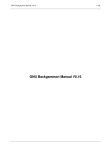
2.2 COORDINATE SYSTEMS
In manipulator control, to indicate the current position/orientation and the target
position/orientation, the standard coordinate system is needed. Inputting the deviation
of position and orientation (rotation angle on the standard axis) for coordinates they can be
controlled.
The coordinate systems used in the motion controller are as follows:
・Base Coordinates ・・The manipulator origin is the basic standard.
Its standard is for all coordinate systems and will never change.
・Mechanical Interface Coordinates ・・The coordinate system is altered by changes of
each axis angle in the manipulator tip coordinate (included tool +
offset.)
(Tip coordinate system)
E1
E2
S3
W2 W1
z
y
Z
TOOL
x
Mechanical Interface
Coordinates
S2
S1
X
Operation
Area
Base
Coordinates
Y
Remark
This illustration is the 7-axis arm composition. For the 6-axis arm, there is no S3-axis.
Memo
Later on, this kind of coordinate system will be needed if combining with motion
mechanism or attaching sensors.
(*)
World
Coordinates
Motion Mechanism
Coordinates
Base
Coordinates
Mech. Interface
Coordinates
(*)In “PA,” the tool coordinates (included offset) are
regarded as the mechanical interface coordinates.
For the coordinate systems not existing in
the motion control section, following the application,
make coordinate-calculations inside the operation control section.
2-4
Tool
Coordinates
Sensor
Coordinates
Operation
Coordinates
Chapter 2. ARM DESIGNATION AND MOTION
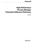
2.3 COORDINATE SYSTEM CREATION
How should the coordinate system shown in the section 2.2 be created:
Here it is explained how to assign coordinate to each link which constructs a
manipulator.
【joint coordinate】
1e
1b
1w
1s
z7
W2
W1
z1
z3
z5
E2
E1
S3
S1
S2
z2 x
1
z4
z6
p
z
a
(0,0,0)
Z
Base
Coordinate
Mech. interface Coordinate
(Tip Coordinate)
y o
x n
Axis
Link
Link
Link
Link
Link
Link
Link
1
2
3
4
5
6
7
1st
2nd
3rd
4th
5th
6th
7th
X
【Link parameters】
Axis Des. Twisting Angle Rotation Angle
S1
S2
S3
E1
E2
W1
W2
Roll
Pitch
Roll
Pitch
Roll
Pitch
Roll
φS1
φS2
φS3
φE1
φE2
φW1
φW2
X
Y
Z
0
0
0
0
0
0
0
0
-1s
0
-1e
0
-1w
0
1b
0
0
0
0
0
0
Remark
This chart shows only the 7-axis arm composition. For the 6-axis arm, there is no Link 3.
Twisting Angles
Roll :Rotation around Z-axis of the base coordinate.
Pitch:Rotation around Y-axis of the base coordinate.
Yaw:Rotation around X-axis of the base coordinate.
Joint Coordinates
Roll coordinate:the same as the base coordinate.
Pitch coordinate:90 degrees diverted around X-axis of the base coordinate.
Yaw coordinate:90 degrees rotated around Y axis of the pitch coordinates.
<A-Matrix>
Any manipulator is constructed with a series of links connected by joints. At each
link (each axis) the coordinate is fixed one by one. At this point, the conversion
matrix showing the relation between a link and another one is called A-matrix. To
summarize: the A-matrix indicates a relative translation and rotation between link
coordinates.
<T-Matrix>
It can be indicated by the A-matrix product if seeing each link from the base
coordinate (the origin. of the manipulator coordinate.)
This A-matrix product is
called T-matrix. T-matrix of each link seeing from the base coordinate is indicated
with Ti(=0Ti).
2-5
y1
Y
Chapter 2. ARM DESIGNATION AND MOTION
(1)Base Coordinate Systems
The base coordinate is the origin of a manipulator. This coordinate itself becomes the
standard coordinate system (the absolute coordinate system) as follows:
T0 =
1
0
0
0
0
1
0
0
0
0
1
0
0
0
0
1
2-6
Chapter 2. ARM DESIGNATION AND MOTION
(2)Mechanical Interface Coordinates
Mechanical interface coordinates (tool tip coordinate) will be created as follows:
・First of all, create the conversion matrix A1 from the manipulator origin, indicating the S1 origin.
→The coordinate of S1 origin located at base coordinate:
T1=T0A1
・Then, create conversion matrix: A2 indicating the S2 origin for the S1 origin (T1 coordinate.)
→The coordinate of S2 origin located at the base coordinate:
T2=T1A2=A1A2
・Then, create conversion matrix: A3 indicating the S3 origin for the S2 origin (T2 coordinate.)
→The coordinate of S3 origin located at the base coordinate:
T3=T2A3=A1A2A3
・Then, create conversion matrix: A4 indicating the E1 origin for the S3 origin (T3 coordinate.)
→The coordinate of E1 origin located at the base coordinate:
T4=T3A4=A1A2A3A4
・Then, create conversion matrix: A5 indicating the E2 origin for the E1 origin (T4 coordinate.)
→The coordinate of E2 origin located at the base coordinate:
T5=T4A5=A1A2A3A4A5
・Then, create conversion matrix: A6 indicating the W1 origin for the E2 origin (T5 coordinate.)
→The coordinate of W1 origin located at the base coordinate:
T6=T5A6=A1A2A3A4A5A6
・Then, create conversion matrix: A7 indicating the W2 origin for the W1 origin (T6 coordinate.)
→The coordinate of W2 origin located at the base coordinate:
T7=T6A7=A1A2A3A4A5A6A7
・Then, create conversion matrix: A tool indicating tool tip for the W2 origin (T7 coordinate.)
→The tool tip coordinate located at the base coordinate:
Ttool=T7Atool=A1A2A3A4A5A6A7Atool
Thus, if it is successively indicated with a conversion for new coordinates, multiply the
conversion matrix of each joint on the right.
To summarize: the finally created Ttool(0Tt)matrix indicates the position / direction of
the mechanical interface coordinate (included the tool) seen from the base coordinate.
Using this matrix, it also makes the conversion from the mechanical interface coordinate
to the base coordinate.
TTOOL =
NOAP
=
nx
ny
nz
0
ox
oy
nz
0
ax
ay
az
0
A
px
py
pz
1
Z
N
P
Y
Tip Orientation Tip position
X
Remark
This is the 7-axis arm composition. For 6-axis arm, there is no A3.
2-7
0
Chapter 2. ARM DESIGNATION AND MOTION
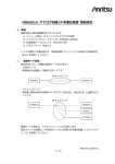
2.4 ROTATION DIRECTION FOR COORDINATE SYSTEMS
Input values for each coordinate as follows.
(1)Input values in the base coordinate
<Position>
・Deviation toward X(△X)
・Deviation toward Y(△Y)
・Deviation toward Z(△Z)
・Velocity toward X(VX)
・Velocity toward Y(VY)
・Velocity toward the V-axis(VZ)
<Orientation>
・Rotation deviation on X(△Yaw)
・Rotation deviation on Y(△Pitch)
・Rotation deviation on Z(△Roll)
・Rotation velocity on X(VYaw)
・Rotation velocity on Y(VPitch)
・Rotation velocity on Z(VRoll)
(2)Input value in the mechanical interface coordinate
<Position>
・Deviation toward X(△x)
・Deviation toward Y(△y)
・Deviation toward Z(△z)
・Velocity toward X(Vx)
・Velocity toward Y(Vy)
・Velocity toward Z(Vz)
<Orientation>
・Rotation deviation on X(△yaw)
・Rotation deviation on Y(△pitch)
・Rotation deviation on Z(△roll)
・Velocity toward X(Vyaw)
・Velocity toward Y(Vpitch)
・Velocity toward Z(Vroll)
2-8
Z
Roll
Pitch
Y
Yaw
X
z
roll
pitch
y
x
yaw
Chapter 2. ARM DESIGNATION AND MOTION
2.5 CONVERSION
Space conversion with a 4x4 Matrix can indicate the conversion of translation and rotation.
Using these conversions and coordinates, they designate the position and orientation of a
manipulator.
(1)Position designation
Position designation (conversion) is to translate X, Y and Z directions of the basic
coordinate T.
Trans ( x,
y,
z )=
1 0 0 x
0 1 0 y
0 0 1 z
0 0 0 1
(2)Orientation designation ( Roll, Pitch, Yaw )
Roll, pitch and yaw is generally used for the orientation designation
(conversion).
In a standard coordinate T, Yaw is the rotation around X-axis. Pitch is the
rotation around Y-axis.
Roll is the rotation around Z-axis.
Memo
As these three conversions are based on the original coordinate, pay attention
to the conversion formula, the multiplication order is reversed.
R P Y ( roll, pitch, yaw )
Processing order
=
=
=
Rot ( z, roll
Cr -Sr
Sr Cr
0
0
0
0
Cr Cp
Sr Cp
-Sp
0
) Rot ( y, pitch ) Rot ( x, yaw )
0
0
Cp
0
Sp
0
0
0
0
1
0
0
1
0
-Sp 0
Cp
0
0
1
0
0
0
1
Cr Sp Sy - Sr Cy
Sr Sp Sy + Cr Cy
Cp Sy
0
However、Sy =
Sp =
Sr =
sin (yaw),
sin (pitch),
sin (roll),
2-9
1
0
0
0
0
Cy
Sy
0
0
-Sy
Cy
0
Cr Sp Cy + Sr Sy
Sr Sp Cy - Cr Sy
Cp Cy
0
Cy =
Cp =
Cr =
cos (yaw)
cos (pitch)
cos (roll)
0
0
0
1
0
0
0
1
Chapter 2. ARM DESIGNATION AND MOTION
Memo
Conversions responding to the rotation angle θ around X, Y and Z-axis are:
Rot ( x, θ )
=
Rot ( y, θ )
=
Rot (z, θ )
=
1
0
0
0
cosθ
0
-sinθ
0
0
0
cosθ -sinθ
sinθ cosθ
0
0
0
1
0
0
cosθ -sinθ
sinθ cosθ
0
0
0
0
2-10
0
0
0
1
sinθ
0
cosθ
0
0
0
0
1
0
0
1
0
0
0
0
1
Chapter 3. CONTROL MODE
Chapter 3. CONTROL MODE
Looking at the nearest point to H/W in the manipulator control, command
values are given to each axis. As the actual operation method, not only makes
each axis move, but also needs complex movements controlling orientation or
the tip position to be straight.
3-1
Chapter 3. CONTROL MODE
3.1 ACTUATING CONTROL MODE
Actuating control methods for PA, are provided as follows:
Also data interpolation will be performed when it operates for all modes.
・Axis angle control
・Axis speed control
・6 direction deviation control for the RMRC base coordinate system
・6 direction velocity control for the RMRC base coordinate system
・Tip coordinate matrix control for the RMRC base coordinate system
・6 direction deviation control for the RMRC mechanical interface coordinate
system
・6 direction velocity control for the RMRC mechanical interface coordinate system
・Redundant axis control for RMRC control
・Teach data acquisition control
・Playback (axis / linear / circle / arc interpolation) control
・Coordinate conversion control for playback
7-axis arm function
・redundant axis control for playback
・Direct control
.. optional function
・Axis angle real-time control
・RMRC real-time control
・Absolute target position / orientation designation control
・others
Direct teaching is optional.
3-2
Chapter 3. CONTROL MODE
(1)Axis angle Control
Operation method ordering each axis target angle or previously defined each axis
value, through the operation controller.
Reference
Programming is explained in Section 6-3.
(2)Tip Position /Tip Orientation Control
Method to shift the tip straight or rotate the tip direction by inputting the tip
position/orientation deviation for the defined coordinate axis by the operation
controller.
The
Motion
controller
calculates
the
linear
interpolation
for
each
tip
position/orientation and control position/orientation feedback.
In PA10, tip position/orientation control is called RMRC control.
Reference
Programming for the 6 axis arm is explained in section 6-4 and for the axis arm,
in section 6-5.
(3)Velocity Control
Operation method to select the axis for velocity control and input command value.
Input to each axis or to the coordinate system axis is accessible.
Reference
Programming is explained in section 6-6.
(4)Redundant Axis Control
7-axis arm function
For the 7-axis arm, the same as PA, there are several axis values at the same tip
position/orientation. The arm, with these characteristics, is called “Redundant axis
arm”.
By controlling this redundant axis, complex movements can be achieved.
For instance, even if the elbow encounters obstacles, this elbow position can be
shifted, without changing the tip position/orientation.
The redundant axis control is the mode restricting each axis of the 7-arm axis to any
direction.
There are two types of redundant axis control, as follows:
・The control restricts the redundant axis altering the tip position/ orientation.
・The control shifts, only, the redundant axis (elbow) position not altering the tip
position/orientation.
Reference
Programming is explained in section 6-5.
3-3
6.11 Playback Control
6.11.1 PTP linear interpolation data and playback control
6.11.2 PTP arc interpolation data and playback control
6.11.3 PTP circle interpolation data and playback control
6.11.4 PTP axis interpolation data and playback control
6.11.5 Teach data playback control mixed with various data
6.11.6 Differences between current point operation and playback control
6.11.7 JUMP rules
6-84
6-85
6-86
6-88
6-89
6-91
6-92
6-94
6.12 Tip Offset Control
6.12.1 Coordinate conversion matrix control
6.12.2 Tip position offset control
6-95
6-96
6-104
6.13 Cube interference
6-110
6.14 Parameter setting
6-112
6.15 Error Information
6.15.1 status transition summary for error occurrence
6-114
6-114
Chapter 7 Library Reference
Header file for Visual C++ (Windows)
Header file for Visual BASIC (Windows)
Error list (Common)
Function list (Index)
Chapter 8 PA Library Compilation
Appendix
Appendix
Appendix
Appendix
1
2
3
4
7-1
7-2
7-14
7-26
7-34
8-1
PA library issuable status table
On PA library return value (error code)
On restart control function after momentary stop during playback control
Sample program instruction
Chapter 3. CONTROL MODE
(7)Real-Time Control
This mode controls the arm in position/orientation or each axis angle, at actual time,
inputting tip position/ orientation or each axis angle every control cyclic time.
The command ( tip position/orientation Matrix or each axis angle every control cyclic
time) has to be issued every time-out.
Reference
Programming is explained in the section 6.8.
3-5
Chapter 3. CONTROL MODE
(5)Direct Control (Optional function)
After switching on the torque control and releasing the brake, this direct control is for
the manually arm operation mode.
This control mode memorizes each axis data as the teach (PTP) data when an arm is
operated manually. It revives the movements through the playback control.
・Simple weight compensation control
Reference
Programming is explained in section 6-7.
(6)Playback Control
This playback control is managed by continuous teach data (each axis value or NOAP)
Between a non continuous teach data the playback control will be interpolated
adjusting the data types.
Teach data 1 ( θS11,θS21,・・・ θW21 )
Teach data 2 ( θS12,θS22,・・・ θW22 )
:
Teach data n ( θS1n,θS2n,・・・ θW2n )
The teach data is as follows:
・PTP for axis interpolation
・PTP for linear interpolation
・PTP for arc interpolation
・PTP for circle interpolation
each axis(θS1~θW2)data
each axis(θS1~θW2)data
each axis(θS1~θW2)data
each axis(θS1~θW2)data
・PTP for linear interpolation tip(NOAP)data
・PTP for arc interpolation
tip(NOAP)data
・PTP for circle interpolation tip(NOAP)data
Interpolation methods are as follows:
・Axis angle interpolation
・Tip linear interpolation
・Tip arc interpolation
・Tip circle interpolation
Reference
Interpolation methods are explained in the section 3.2 – 3.5.
Programming is explained in the section 6.10 and 6.7.
Memo
The teaching data is the PTP data. The PTP data is the abbreviation for
“Point to Point”. The trajectory between different data is haphazard. But
when the playback control is operated, the interpolation has to be surely
performed between different PTP data.
3-4
Chapter 3. CONTROL MODE
3.2 Trajectory Control Mode
How to operate each axis or tip position/orientation of a manipulator:
In PA10, the interpolation is as follows:
a. Trajectory Interpolations
・Axis angle interpolation
・Tip linear interpolation
・Tip arc interpolation
・Tip circle interpolation
・Tip orientation interpolation
b.Velocity Control
・Constant velocity interpolation
・( Acceleration + Constant velocity ) Interpolation
・( Constant velocity + deceleration) Interpolation
・( Acceleration + Constant velocity + deceleration) Interpolation
Control Mode
a.Trajectory interpolation
Each Axis Control
Each Axis Interpolation
Tip Position Control
Tip Linear Interpolation
Tip Orientation Control
Tip Orientation Interpolation
Each Axis Interpolation
Tip Linear Interpolation
Playback Control
Tip Orientation Interpolation
Tip Arc Interpolation
Tip Orientation Interpolation
Tip Circle Interpolation
3-6
b.Velocity Control
Chapter 3. CONTROL MODE
3.3 Axis Angle Interpolation
Here is the explanation for each axis angle control in the trajectory control mode.
Each axis angle control
<Input value>
target angle(θrS1,θrS2,・・θrW2)
<Calculation>
① Calculate deviation angle and subtract the current value from the target one,
at each axis.
θrS1 - θcS1
ΔθS1
ΔθS2
=
θrS2 - θcS2
:
:
ΔθW2
θrW2 - θcW2
.
② From the calculation, dividing each axis deviation by each axis default
velocity, the axis, obtaining the biggest shifting time, is defined as the basic axis
of interpolation.
ΔTS1
ΔTS2
:
ΔTW2
=
ΔθS1 / VS1
ΔθS2 / VS2
:
ΔθW2 / VW2
The axis obtained the biggest ΔTi。is defined as the standard of interpolation.
③ Calculate each axis command angle on the basis of the interpolation basic axis
deviation(Δθi).
In the interpolation method, calculate the target trajectory
( command angle ) to control the velocity to form the letter “S” shape.
Reference
For the velocity control, refer to the section 3.5.
3-7
Chapter 3. CONTROL MODE
3.4 RMRC Tip Interpolation
The method to shift a manipulator tip position/orientation to the next target
position/orientation in the trajectory control mode is explained here.
Tip position/orientation interpolation methods currently provided in PA10 are three as
follows:
・Linear Interpolation ・・・The tip trajectory is straight. The tip orientation is
concurrently interpolated, too.
・Arc Interpolation ・・・The tip trajectory is an arc. The tip orientation is
concurrently interpolated, too.
・Circle Interpolation ・・・The tip trajectory is a circle.
The target tip position/orientation “ T r n ” is calculated from interpolation every
sampling period to shift on the trajectory to the target position/orientation from the
current position/orientation.
7-axis arm function
For the 7-axis arm, when the redundant axis control modes – “S3-axis restriction”
and “S3-axis interpolation” – are selected and the interpolation above is operated,
the S3-axis angle deviation (difference between the current angle and the target
angle) is simultaneously interpolated and target “S3-axis” angles are calculated every
sampling period.
For trajectory interpolation methods, the target tip position/orientation trajectory
(command angle) is calculated for velocity to form the letter “S” shape.
Reference
Refer to the section 3.5 for velocity control.
3-8
Chapter 3. CONTROL MODE
(1)Linear interpolation
Tip orientation rotation angle: e
interpolation
Pr
Pc
Tip position shifting value: L
<When the redundant axis control mode is NOT “S3-axis restriction” and “S3-axis
interpolation mode in 6-axis and 7-axis arm>
1.
2.
3.
4.
5.
6.
7.
OUTLINE PROCEDURE FOR LINEAR INTERPOLATION
Calculate the current tip position and the tip orientation (Tc).
Calculate the target tip position and the tip orientation (Tr).
Calculate the tip moving distance (L) from the current tip position and the target
position.
Calculate the tip orientation/rotation angle (θ) from the current orientation and the
target tip orientation.
To simultaneously operate the position and the orientation, the standard must be
chosen.
Following the selected velocity control method, interpolate and calculate the target tip
position/target orientation (Tr1,・・・ ,Trn-1,Trn,・・・ Tr) of each sampling.
If the work coordinate conversion Matrix is designated, multiply “ T r n ” by the
coordinate conversion Matrix.
<When the redundant axis control mode is “S3-axis restriction” and “S3-axis
interpolation mode>
7-axis arm function
1.
2.
3.
4.
5.
6.
7.
8.
OUTLINE PROCEDURE FOR LINEAR INTERPOLATION
Calculate the current tip position and the tip orientation (Tc).
Calculate the target tip position and the tip orientation (Tr).
Calculate the tip moving distance (L) from the current tip position and the target
position.
Calculate the tip orientation/rotation angle (θ) from the current orientation and the
target tip orientation.
Calculate the S3-axis angle/rotation angle(θS3) from the current S3-axis angle and
the target S3-axis angle.
To operate the position and the orientation, the standard for interpolation must be
chosen from the position, the orientation or the S3-axis.
Following the selected velocity control method, interpolate and calculate the target tip
position, the target orientation and the S3-axis of each sampling.
If the work coordinate conversion Matrix is designated, multiply “Trn” by the coordinate
conversion Matrix.
3-9
Chapter 3. CONTROL MODE
(2)Arc & Circle Interpolation
Arc Interpolation
Circle Interpolation
Tip Shifting Direction
P2
θ1
P1
P1
θ1
P3
0
r 0
Vec
P3
P2
r
Vec
P3
Orientation Rotation A
θ
P1
Orientation rotation Angle:θ2 = 0
Position Shifting rotation Angle: θ1 = 2π
<When the redundant axis control mode is NOT “S3-axis restriction” and
“S3-axis interpolation mode in 6-axis and 7-axis arm>
1.
2.
3.
4.
5.
6.
7.
8.
9.
1.
2.
3.
4.
5.
6.
OUTLINE PROCEDURE FOR ARK & CIRCL INTERPOLATION
Calculate the current tip position (P1) and the tip orientation (T1).
Calculate the tip position and the tip orientation (T2) of the passing point (P2).
Calculate the tip position and the tip orientation (T3) of the target value (P3). In the
case of the circle, P3-point is also the passing point.
Calculate the center point (O), the semi-diameter (r) and the normal vector (Vec) of
the circle trajectory from three points.
Calculate the angle of the tip accurate motion (θ1) from the tip position of the current
value P1 and P3. For the circle,θ1 = 2π.
Calculate the rotation angle of the tip orientation (θ2) from the tip position of the
current value P1 and P3. For the circle,θ2 = 0 (current orientation maintained.)
To simultaneously operate the position and the orientation, the standard must be
chosen.
Following the selected velocity control method, interpolate and calculate the target tip
position/target orientation (Tr1,・・・ ,Trn-1,Trn,・・・ Tr) of each sampling.
If the work coordinate conversion Matrix is designated, multiply “ T r n ” by the
coordinate conversion Matrix.
<When the redundant axis control mode is “S3-axis restriction” and “S3-axis
interpolation mode>
7-axis arm function
OUTLINE PROCEDURE FOR LINEAR INTERPOLATION
Calculate the current tip position (P1) and the tip orientation (T1).
Calculate the tip position and the tip orientation (T2) of the passing point (P2).
Calculate the tip position and the tip orientation (T3) of the target value (P3). In the
case of the circle, P3-point is also the passing point.
Calculate the center point (O), the semi-diameter (r) and the normal vector (Vec) of the
circle trajectory from three points.
Calculate the angle of the tip accurate motion (θ1) from the tip position of the current
value P1 and P3. For the circle,θ1 = 2π.
Calculate the rotation angle of the tip orientation (θ2) from the tip position of the
current value P1 and P3. For the circle,θ2 = 0 (current orientation maintained.)
3-10
Chapter 3. CONTROL MODE
7.
Calculate rotation angle (θS3) if S3-axis orientation from the S3-axis
angle, of the current value (P1) and the S3-axis angle of the target value
(P3). In the case of the circle, it is (θS3) = 0.0 [rad] ( in the case of
circle interpolation, S3-axis DOES NOT move and make the same motion as
“S3-axis fixed”.
8. To operate the position and the orientation, the standard for interpolation
must be chosen from the position, the orientation or the S3-axis.
9. Following the selected velocity control method, interpolate and calculate the
target tip position/target orientation/target S3-axis angle of each sampling.
10. If the work coordinate conversion Matrix is designated, multiply “Trn” by
the coordinate conversion Matrix.
3-11
Chapter 3. CONTROL MODE
3.5 Velocity Control
When a manipulator plus a machine operator perform, if, command value is given
intermittently, it causes undesirable mechanical oscillation. For this reason, the
command speed at the start has to be controlled, to gradually accelerate and at stop to
gradually decelerate.
On manipulator trajectory, velocity is generally controlled to make a trapezoid wave.
With this trapezoid wave, the acceleration wave becomes non continuous. It causes
acceleration shock and mechanical oscillation. In PA10, to create a target trajectory to
reduce acceleration shock, interpolation methods are employed to create the letter “S”
shaped target trajectory for velocity.
This satisfies conditions to keep each curve continuity and hold the maximum velocity,
lower. The most reliable curve, even if used in a situation when the load characteristic
is unpredictable, the maximum velocity is lowered
Uniform Velocity
Start (Acceleration)
Start (deceleration)
Angle
Interpolation
Target Angle: θ
Position
Angle:θ
Velocity:v
Accelelation:
These options below are available for a velocity control type.
0:Uniform velocity
1:with Acceleration
2:with Deceleration
3:with Acceleration and Deceleration
Memo
For position change, the trapezoid control is available. Not available for velocity
change. When in a continuous movement as:(ex)p1→p2 is v1[mm/s], p2→p3 is
v2[mm/s], velocity command is intermittently changed at p2 point. In this case,
velocity command intermittent change has to be lowered and controlled at the
servo driver side.
3-12
Chapter 4
Chapter 4.
Motion & Operation Control Section
Motion & OperationControl Section
The PA controller consists of two sections shown below:
• Motion Control Section
• Operation Control Section (man-machine controller)
4-1
Chapter 4
Motion & Operation Control Section
4.1 Motion Control Section
The motion control section – the controller handles the basic control for PA –
operates following each control mode explained in chapter 3. The limitation cycle is
2ms.
Regarding the program for this section, as long as PA is employed, even if the
operation contents are changed, the program remains the same.
4-2
Chapter 4
Motion & Operation Control Section
4.2 Operation Control Section
The operation control section – the controller handles the operation procedures. The
program for this section changes depending on the operation: (on each application: weddings,
painting, etc)
The standard software for PA: the operation support program (man- machine) and PA
Library (the motion and control section and interface section) are provided.
The motion control board is compatible with PCI bus. Employ a PC with PCI bus sold in
the market.
Operation Control Section
Operation
support program
Operation Control PC
I/F
Written by C,
basic language
PA library
Implemented
with DLL
PCI bus Driver
device
Driver
PCI bus
Motion Control Board
Motion Control Section: control cycle : 2ms
Application development
To develop and implement an application a device driver is needed besides PA library.
With PCI bus sold in the market, using “WinnRT” (created by bSQUARE Co.).
The PA Library is created through the DLL form. The program will be kinetically linked
when it is employed. The standard Windows version “PA library is created by Compiler
Visual C ++ Ver. 6.0. Some application samples, created by Visual C++ and Visual BASIC,
are attached.
4-3
Chapter 4
Motion & Operation Control Section
4.3 Operation & Motion Control Section Interface
The Operation section and the Motion Control section are connected by PCI bus.
The memory area is shared at the PCI space.
The operation control section sets the target command (event) to this memory area. The
motion control section operates following a event. The arm movement can be observed at
actual time.
Using this memory area, the one provided to ease the motion control section from the
operation one, is: the “PA library.”
4-4
Chapter 5
Chapter5
Program Development & Processing Conditions
Program Development & Processing Conditions
5- 1
Chapter 5
Program Development & Processing Conditions
5.1 Development & Processing Conditions
For processing conditions, if you intend to provide your own operation control section
(Personal Computer), you must need the following:
・OS
:Windows NT/2000/XP
・Memory
:More than 128 MB
Further more, for development, the following are needed.
・Compiler:Visual C++ Compiler Ver.6.0 or
Visual BASIC Compiler Ver.6.0
5.2 PA Library Status
The PA library stands for:
・A library to develop an application program for the operation control section.
・ The interface library to ease the operation of all actuating functions for the motion
control section. To access the motion control CPU, besides the PA library, a driver
for PCI bus created by the device driver – WinRT – sold in the market, is needed.
・ The PA library is the DLL (Dynamic-link library) model created employing Visual C++
ver.6.0.
WPRM
Application
Program
WRUN
Operation Support
Operation Support
Operation
Parameter setting
Mode
(WPRM)
Visual Basic
Visual Basic
3D
Simple
Simulator
(3D)
Visual C++
PA library
(Papci.DLL)
Visual C++
Operation
control Section
PCI bus
driver
WinRT
PCI bus
Motion Control
Software
5- 2
Chapter 5
Program Development & Processing Conditions
5.3 PA library Directory Composition
The PA library is provided by the CD-ROM.
When the CD-ROM is set, installation starts automatically. (For further information,
refer to the installation manual.)
Reference
The PA library compositions provided in PA are as follows:
\ WinPApci (Default name of installation destination)
BIN
••• Execution file
Passage.exe
Wprm.exe
INCLUDE ・・・ Header file of PA library
PA.H PA library prototype declaration (for development employing Visual C++)
PAERR.H PA library error information declaration (for development employing Visual C++)
PACMD.H
PACTL.H
File needed for PA library construction
PAMMC.H
PA.BAS
PAERR.BAS for development with Visual BACIS
HELP
・・・ Online help file
PAHELP.HLP
SRC
LIB ・・・ PA library source file
PA_CUB.C
CUBE information
PA_DIO.C
Digital I/O
PA_DIR.C
Direct control mode
PA_DPD.C
Real-time T-matrix control
Relatedto additional functions (information acquisition)
PA_EGT.C
VMEinterface connected to the motion control section
PA_ETC.C
PA_EXT.C
Related to additional functions (control)
PA_GET.C
Arm information acquisition
PA_JMP.C
JUMP data
PA_JOU.C
Redundant axis/velocity control
PA_MOD.C
Related to teach mode
PA_MOV.C
initial setting/each axis control/RMRC
PA_MTX.C
Coordinate conversion matrix setting
PA_PNT.C
Teach/playback control
PA_PRM.C
Parameter alteration
PA_PRV.C
Related to parameter loading/saving
PA_SET.C
Basic orientation registration
PA_VEL.C
Velocity mode selection
PCI ・・・ PA library (for PCI) project file
PA_PCI.C
related to PCI-bus access
PCI.DEF
Default definition file
PCI.DSW
Project work space
PCI.DSP
project file
5- 3
Chapter 5
Program Development & Processing Conditions
SAMPLE
MFC
EX1
••• Sample program employing MFC
EX1.CPP
EX1.ICO
EX1.H
EX1.RC2
EX1.RC EX1DLG.CPP
EX1DLG.H
RESOURCE.H
STDAFX.CPP
STDAFX.H
EX1.DSW
EX1.DSP
VC
EX1•••Sample program employing VisualC++
DLGPROC.CPP MAIN.CPP
RESOURCE.H
EX1.RC
EX1.DSW
EX1.DSP
EX1.EXE
EX2•••Sample program employing VisualC++
DLGPROC.CPP MAIN.CPP
RESOURCE.H
EX2.RC
EX2.DSW
EX2.DSP
EX2.EXE
VB
EX1•••Sample program-1 employing VisualBasic
MAIN.BAS
DEFINE.BAS
FUNC.BAS
AXISOPE.FRM
EX1MAIN.FRM EX1.VBP
EX1.EXE
EX2•••Sample program-2 employing VisualBasic
MAIN.BAS
DEFINE.BAS
FUNC.BAS
EX2MAIN.FRM
EX2.EXE
EX2.VBP
EX3 •••Sample program-3 employing VisualBasic
EX3.VBP
EX3.FRM
JS.BMP
EX3.EXE
DLLJS
PAJS.DEF PAJS.DSP
PAJS.DSW PAPAJS.C
OCXJS
PAJS.VBP MODULE1.BAS
PAJS.LIB PAJS.CTL
WINDOWS
SYSTEM
PAPCI.LIB
PAPCI.DLL
Asycfilt.DLL
FLGDJP.DLL
olepro32.DLL
SPR32X30.ocx
Stdole2.tlb
5- 4
PA library (for PCI-bus) – Import library
PA library (for PCI-bus) – DLL
CMDLGJP.DLL
Msvbvm60.DLL
VB6JP.DLL
Comdlg32.ocx
COMCAT.DLL
oleaut32.DLL
mfc42.DLL
MSFLXGRD.ocx
Chapter 5
Program Development & Processing Conditions
Additionally, if the operation support software is purchased together, the following files
are installed into the system directory.
CMCTLJP.DLL MSSTDFMT.DLL
msvcrt.DLL
scrrnjp.DLL
Scrrun.DLL
STDFTJP.DLL
MSCMCJP.DLL
MSCOMJP.DLL
MSCOMM32.ocx MSCOMCTL.ocx
Remark
・ Files needed to develop an application program for the operation control section
employing Visual C++ (Ver.6.0) are the following, indicated on gray background:
PA.H
PAERR.H
PAPCI.LIB
PAPCI.DLL(needed for implementation)
・ Files needed to develop an application program for the operation control section
employing Visual BASIC (Ver.6.0) are the following, indicated on gray background:
PA.BAS
PAERR.BAS
PAPCI.DLL(needed for implementation)
5- 5
Chapter 5
Program Development & Processing Conditions
5.4 Notes for application development employing Visual C++
(1)Header files are needed to be included.
Using the PA library, if an application program is developed employing Visual C++ ver.6.0,
the following header files have to be included. (using MFC, likewise.)
PA.H
・・・・ PA library prototype declaration is described.
PAERR.H ・・・・ PA library error code declaration is described.
<Setting method> Choose “Setting…” inside “Project” of the menu bar, then, choose
“the preprocessor” in the category of C/C++, then, set the path (c:¥winpapc¥include)
to the header file of the PA library.
(2)Needed library files to be linked.
As far as developing an application employing Visual C++ Ver.6.0, using the PA library,
the following import library files have to be linked.
PAPCI.LIB ・・・・ The import library file including the PA library.
<Setting Method> Choose “Setting…” inside “Project” of the menu bar, then, choose
“general” in the link category, then, set the PA library intended to be linked.
Windows2000 or NT c:\winnt\system32\papci.lib
Windows XP
c:\windows\system32\papci.lib
5- 6
Chapter 5
Program Development & Processing Conditions
(3)Structural Member Alignment Alteration
Structural member alignment has to be set for 2 bytes. (default is 8 bytes)
<Setting Method> Choose “Setting…” inside “Project” of the menu bar, then choose
“code creation” in the C/C++ category, then, change the structural
member alignment for 2 bytes.
(4)Needed DLL file for processing
To process the application program the following DLL is needed to be located in the
designated place:
Windows2000/NT: \WINNT\SYSTEM32,
Windows XP:
\WINDOWS\SYSTEM32.
(There is no need to operate any linking or such.)
PAPCI.DLL ・・・・ The file keeping the PA library processing module.
5- 7
Chapter 5
Program Development & Processing Conditions
5.5 Notes for application development employing Visual BASIC
(1)Necessary header files to include
Using the PA library, if develop an application program employing BASIC ver.6.0, add the
following header files. (the standard module file) to the “project.”
PA.BAS
・・・・ The prototype declaration is described when load the PA
library created with C-programming language employing BASIC.
<Setting method> Choose “Add the standard module” inside “Project” of the menu bar,
then, add “ps.bas.”
(2)Necessary DLL file for implementation
To process the application program the following DLL is needed to be located in the
designated place:
Windows2000/NT: \WINNT\SYSTEM32
Windows XP:
\WINDOWS\SYSTEM32.
(There is no need to operate any linking or such.)
PAPCI.DLL ・・・・ The file keeping the PA library processing module.
5- 8
Chapter 6
Programming
Chapter 6 Programming
How to create an application using the PA library.
6-1
Chapter 6
Programming
6.1 Control Arm
(1)6-axis and 7-axis arm
The PA library for 6-axis and 7-axis is described as the same.
Some libraries can only be used for the 7-axis arm, not for the 6-axis one. A
processable library inter-lock is checked at the motion control side.
For the 6-axis arm, on command values to each axis, the S3-axis
(configuration [2]) value becomes invalid.
(example)
Axis value
Velocity command Value
Type Declaration
ANGLE axis
axs.S1
axs.S2
axs.S3
axs.E1
axs.E2
axs.W1
axs.W2
float speed[7]
speed[0]
speed[1]
speed[2]
speed[3]
speed[4]
speed[5]
speed[6]
6-axis arm
7-axis arm
1st axis:S1
2nd axis:S2
(not used)
3rd axis:E1
4th axis:E2
5th axis:W1
6th axis:W2
1st axis:S1
2nd axis:S2
3rd axis:S3
4th axis:E1
5th axis:E2
6th axis:W1
7th axis:W2
1st axis:S1
2nd axis:S2
(not used)
3rd axis:E1
4th axis:E2
5h axis:W1
6th axis:W2
1st axis:S1
2nd axis:S2
3rd axis:S3
4th axis:E1
5th axis:E2
6th axis:W1
7th axis:W2
(2)Plural Arm Control
For one operation control PC (Personal Computer), plural motion control boards can
be inserted. Besides, two arms can be controlled with one motion control board. In
the case of plural arms, the controlled arm is classified with its own number.
For the PA library, all arm numbers are needed.
pa_opn_arm(ARM armno,……..)
ARM
=ARM0
=ARM1
=ARM2
:
=ARM16
Reference
For arm number settings, refer to “the PROGRAMING MANUAL (ADDITIONAL
EDITION).”
6-2
Chapter 6
Programming
6.2 Common Items
On the control programming using the PA library, there are some that must be
known and followed through.
(1)Synchronization between controllers
One command is issued for one PA library from the operation control section to
the motion control section. The motion control section performs the
motion/processing, responding to this command.
Synchronization between controllers is operated by the control counter. When the
motion/processing is completed, the count value of the control counter will be
increased one counter value.
During processing, if any error occurs, it stops processing, adds one counter value,
then, returns an error code.
If the return value (error code) of the library shows “ERROR-OK.” It means the
control is normally terminated.
(2)Minimum required programming procedures
If controlling the motion control section using the PA library, the following
descriptions are needed:
①PA Library Initialization :pa_ini_sys
Declaration to use the PA library.
②Open Arm (Control Arm Selection) :pa_opn_arm
Plural motion control sections (arm) can be controlled by one operation control
section. The control arm and the number of the arm (ARMO ~ ARM15) have to be
designated by the motion control section.
Reference
For the arm number setting, refer to the section 4.3 – the operation & motion
control interface.
③Control Start (Motion Control Section) : pa_sta_arm or pa_sta_sim
If issuing the “pa_sta_arm” library, the communication with the servo driver will be
started. If issuing the “pa_sim_arm” library, the simulation mode starts. In this
mode, regarding all commands issued from hereafter, the motion and the program
can be confirmed without operating any actual machine.
④Control Stop (Motion Control Section) : pa_ext_arm or pa_ext_sim
If issuing the “pa_ext_arm” library, the communication with the servo driver will be
terminated. If issuing the “pa_ext_arm” library, the simulation mode will be
terminated.
⑤Close the arm
: pa_cls_arm
Separates the selected arm from the motion control section.
⑥PA library Exit
: pa_ter_sys
6-3
Chapter 6
Programming
Explanation on the programming employing samples.
・ Example: for Visual C++ – the one written with the visual C++6.0
programming language is indicated.
・ It is the same as other C-programming language (either Windows or not)
・ Example: for Visual BASIC – the one written with the visual BASIC
programming language is indicated.
Remark
In the sample, making easier to understand the description method, function return
values ARE NOT checked. When you actually make programming, check any error
shown by a return value.
Depending on the error type, the motion control section terminates the control
automatically.
Reference
Regarding errors, refer to the error table.
Program Description:
Example: for Visual C++
pa_ini_sys();
pa_opn_arm( ARM0 );
pa_sta_arm( ARM0 );
:
Motion Description Section
:
pa_ext_arm( ARM0 );
pa_cls_arm( ARM0 );
pa_ter_sys();
... PA library initialization
... 1st arm open
... Control Start
... Control Stop
... 1st arm close
... PA library termination
Example: for Visual BASIC
Dim ret As Long
:
ret = pa_ini_sys()
ret = pa_opn_arm( ARM0 )
ret = pa_sta_arm( ARM0 )
:
Motion Description Section
:
ret = pa_ext_arm( ARM0 )
ret = pa_cls_arm( ARM0 )
ret = pa_ter_sys()
... PA library initialization
... 1st arm open
... Control Start
... Control Exit
... 1st arm close
... PA library termination
This is the minimum necessary description library.
6-4
Chapter 6
Programming
(3)Processing during a library performance
Explaining processing methods while a library describing motion is performing.
func = WM_WAIT
:Wait until the arm motion is terminated.
= WM_NOWAIT:No wait until the arm motion is terminated.
func = WM_WAIT : Wait until the arm motion is terminated
<Library Processing Contents>
・Issues command to the motion control section.
・Observes the motion termination.
・If any error occurs, terminates processing. An error number is shown as a
return value.
Example: for Visual C++
if( pa_exe_hom(ARM0, WM_NOWAIT) != ERR_OK )
Error termination
else
Normal termination
Example: for Visual BASIC
Dim ret As Long
ret = pa_exe_hom(ARM0, WM_NOWAIT)
If ret <> ERR_OK Then
Error termination
Else
Normal termination
End If
6-5
Chapter 6
Programming
func = WM_NOWAIT : No wait until the arm motion is terminated
<Library Processing Contents>
・Issues commands to the motion control section.
・If any error occurs, terminates processing. An error number is shown as a
return value.
・Confirmation and error observation are not performed at the motion
termination.
Example: for Visual C++
long new, old;
long err;
:
pa_get_cnt(ARM0, &old); ...Control counter setting before the command issue
pa_exe_hom(ARM0, WM_NOWAIT);
while(1){
if(( err=pa_get_cnt(ARM0,&new))!=ERR_OK){
An error occurrence processing
break;
}else if( new != old ){
Motion termination processing
break;
}else{
Processing during performance (Example; axis indication)
}
}
Example: for Visual BASIC
Dim new As Long
Dim old As Long
Dim err As Long
:
err = pa_get_cnt(ARM0, old) ...Control counter setting before the command issue
err = pa_exe_hom(ARM0, WM_NOWAIT)
Do While 1
err = pa_get_cnt(ARM0, new)
If err <> ERR_OK Then
An error occurrence processing
Exit Do
Else
If new <> old Then
Motion termination processing
Exit Do
Else
Processing during performance (Example; axis indication)
End If
End If
Loop
6-6
Chapter 6
Programming
6.3 Axis Angle Control
Method to control from the operation control section providing axis target angle.
The motion control section calculates each axis interpolation and controls angle
Current angle of axis
feedback.
θ
θ=[θS1・・θW2]
Current value
Current angle of axis
Kθ
After interpolation
Each angle gain
θ=[θS1・・θW2] - Angle deviation
・
Δθ=[ΔθS1・・ΔθW2]
KS1
0
Joint axis
θ
+
KS2
0
Velocity command
KW2
The method to provide target values is as follows:
<Method to input angles>
Axis angle control( θS1,θS2,・・・ θW2 )
<Axis Angle Control> The method to use a orientation previously registered.
・Basic Orientation Control
・Escape orientation control
・Safety Orientation Control
Axis Angle Interpolation Method
This method to control the selected axis to the target angle, calculating axis
interpolation.
This method interpolates the velocity command to form a letter “S” shape.
The motion velocity is interpolated adjusting to the default velocity.
Start-up (acceleration) time
Uniform Velocity
Target Angle (command value)
Angle:θ
Axis default velocity
Velocity:v
Acceleration:ω
6-7
Shutdown (deceleration) time
Chapter 6
Programming
6.3.1 Axis Angle Control
Designates axes to be controlled and provides target angles.
Program Description::
Example: for Visual C++ To control only S1,S2 and E1 at 90 [deg]
:
ANGLE angle;
:
angle.s1 = 1.57; (= 90.0 * M_PI / (double)180.0)
angle.s2 = 1.57;
angle.e1 = 1.57;
pa_exe_axs( ARM0, S1|S2|E1, & angle, WM_NOWAIT );
Example: for Visual BASIC
:
Dim ret As Long
Dim axs As Long
Dim agl As ANGLE
:
agl.s1 = 1.57
agl.s2 = 1.57
agl.e1 = 1.57
axs = S1 Or S2 Or E1
ret = pa_exe_axs( ARM0, axs, agl, WM_NOWAIT )
The motion speed is adjusted to the default one and interpolated forming a letter “S”
shape.
6-8
Chapter 6
Programming
6.3.2 Axis Orientation Control
This control method is the same as the axis control.
・Basic Orientation
All Axes :0 [deg]
・Escape Orientation
S2
:30[deg]
E1
:90[deg]
W1
:60[deg]
Others: 0[deg]
・safety Orientation
S2
E1
W1
Others
: 45[deg]
: 90[deg]
:-45[deg]
: 0[deg]
Alteration methods for each orientation angle are:
・Method to input the angle.
・Method to replace with a current angle.
These values are erased when the power is off.
default value, use the parameter setting program.
(ex) pa_set_hom
(ex) pa_def_hom
To change the arm parameter
Program Description:
Example: for Visual C++
ANGLE angle;
:
pa_exe_esc( ARM0, WM_NOWAIT );
to default escape orientation.
:
angle.s1 = 1.57;
[rad]( = 90.0[deg]*M_PI/(double)180.0)
angle.s2 = 1.57;
angle.e1 = 1.57;
:
angle.w2 = 1.57;
pa_set_esc( ARM0, & angle );
escape orientation alteration
pa_exe_esc( ARM0, WM_NOWAIT );
all axes to 90[deg]
:
angle.s1 = 0.785;
angle.s2 = 0.785;
pa_exe_axs( ARM0, S1|S2, & angle ,WM_NOWAIT);
to S1,S2 = 45[deg]
:
pa_def_esc( ARM0 );
loading as escape orientation
6-9
Chapter 6
Programming
Example: for Visual BASIC
Dim agl As ANGLE
Dim ret As Long
Dim axs As Long
ret = pa_exe_esc( ARM0, WM_NOWAIT )
to the default escape orientation.
agl.s1 = 1.57
agl.s2 = 1.57
agl.e1 = 1.57
:
agl.w2 = 1.57
ret = pa_set_esc( ARM0, agl )
escape orientation alteration
ret = pa_exe_esc( ARM0, WM_NOWAIT )
all axes to 90[deg]
:
agl.s1 = 0.785
agl.s2 = 0.785
axs = S1 Or S2
ret = pa_exe_axs( ARM0, axs, agl ,WM_NOWAIT)
:
ret = pa_def_esc( ARM0 )
loading as escape orientation
It would be useful to register angles often used following operation purposes.
(*1) The arm parameter is the file setting data needed for a control, located in the
motion control section.
Reference
For further information, refer to “parameter setting” in the section 6.13.
The contents can be seen with the command – pa_get_prm – from the operation
control section. They cannot be directly changed in the program.
But, the operation support program (parameter setting) for alteration is provided.
Reference
For the alteration method, refer to the operation support program (parameter
setting) instruction.
6-10
Chapter 6
Programming
6.4 Tip Position/Orientation (RMRC) Control: 6-axis arm
The following explanation about the tip position/orientation control for the 6-axis arm
is the summarized one. For the 7-axis arm, it is explained in the section 6.5.
6.4.1 Tip Position/Orientation (RMRC) Control
PA10 tip position/orientation (RMRC) control is the method to control arm
providing its tip position/orientation as the target value from the operation control
section.
The motion control section calculates interpolation of each tip
position/orientation and controls the position feedback.
Current position/orientation
At the base coordinate system
T =[noap]
Target position orientation
At the base coordinate
After interpolation
T =[noap]
Position coordinate
conversion
θ
Current value
KP
Position control gain
- Position orientation
0
deviation KX
+
KY
0
KRoll
・
Joint angle
Coordinate conversion
・
θ = J#・Vpw
Memo
In PA10, the tip position/orientation control is called RMRC control.
As target value, there are input values below:
・Tip Position Deviation( ΔX,ΔY,ΔZ )
・Tip Orientation Deviation( ΔYaw,ΔPitch,ΔRoll )
・Tip Position/Orientation
nx ox ax px
ny oy ay py
nz oz az pz
Tip position/orientation (RMRC) control are as follows:
・Tip position deviation control
・Tip position orientation control
・Absolute position/orientation designation control
・Tip position/orientation/velocity control
・Current point motion control (Tip linear motion)
・Playback control (Except data for PTP axis interpolation)
・RMRC real-time control mode
6-11
θ Joint axis
Velocity command
Chapter 6
Programming
Tip Position/Orientation Interpolation Method
This method calculates the tip position/orientation interpolation and controls the
tip to the input target position/orientation.
This method interpolates the velocity command to form a letter “S” shape.
The motion velocity, adjusting to the position/orientation default velocity, is
interpolated to form a letter “S” shape.
Start-up (acceleration) time
Uniform Velocity
Target Position/Orientation
Position/orientaion
T=[NOAP]
Position/Orientation Default Velocity
Velocity:v
Acceleration:ω
6-12
Shutdown (deceleration) time
Chapter 6
Programming
(1)Tip Position Deviation Control
Position deviations (ΔX,ΔY,ΔZ) from the current tip position are provided to
each axis in the selected coordinate system.
・Base coordinate tip position control:pa_mov_XYZ( ARM0, dX, dY, dZ, WM_WAIT )
・Mechanical interface coordinate tip position control:pa_mov_xyz( ARM0, dx, dy, dz,
WM_WAIT)
( Visual BASIC: pa_mov_XYZ0( ARM0,dx,dy, dz, WM_WAIT ) )
In Visual BASIC, there is no distinction between capital and small letters.
Control Method:
・ The target position is defined by adding the current tip position to the input
position deviation.
・ The tip position is interpolated linearly.
・ The arm parameter default tip linear velocity is interpolated to form the letter
“S” shape
・The tip orientation does not change.
Program Description:
① Adjusts the axis value to the RMRC controllable one.: pa_exe_esc
The possible start range for RMRC control is limited.
The entry to the RMRC control is not allowed when E1=0[deg].
The entry to the RMRC control from the basic orientation is not allowed. One of
the ways to enter the RMRC control is to shift to the escape orientation.
② Chooses the coordinate system and provides deviation. : pa_mov_XYZ
It moves 100 (mm) toward X (axis) in the base coordinate.
A coordinate system selection depends on the intended direction to shift. The
one to be applied should be chosen.
Example: for Visual C++
:
pa_exe_esc( ARM0, WM_WAIT );
・・・to RMRC controllable orientation
pa_mov_XYZ( ARM0, 100.0, 0.0, 0.0,WM_WAIT );
:
・・・Proceed X=100.0 in the base coordinate.
Example: for Visual BASIC
Dim ret As Long
:
ret = pa_exe_esc( ARM0, WM_WAIT )
ret = pa_mov_XYZ( ARM0, 100.0, 0.0, 0.0,WM_WAIT )
6-13
Chapter 6
Programming
(2)Tip Orientation Deviation Control
Orientation deviations (ΔYaw,ΔPitch,ΔRoll) from the current tip orientation are
provided to each axis in the selected coordinate system.
・Base coordinate tip orientation control:
pa_mov_YPR(ARM0, dYaw,dPitch,dRoll,WM_WAIT)
・Mechanical interface coordinate tip orientation control:
pa_mov_ypr(ARM0,dyaw,dpitch,droll, WM_WAIT )
(In the case of Visual BASIC: pa_mov_YPRO(ARM0,dyaw,dpitch, droll, WM_WAIT) )
Control Method:
・The tip position does not change.
・The target orientation is defined by adding the current tip orientation to the input
orientation deviation.
・The rotation angle deviation of the tip orientation is interpolated.
・The arm parameter default tip rotational velocity – the rotational velocity – is
i nterpolated to form the letter “S” shape
・
Program Description:
① Adjusts the axis value to the RMRC controllable one.: pa_exe_esc
The possible start range for RMRC control is limited.
The entry to the RMRC control is not allowed when E1=0[deg].
The entry to the RMRC control from the basic orientation is not allowed. One of
the ways to enter the RMRC control is to shift to the escape orientation.
② Chooses the coordinate system and provides deviation.: pa_mov_ypr
It moves around an axis in a mechanical interface coordinate. The tip position
does not change. If tool information/offset values are set, it rotates around the tip.
A coordinate system selection depends on the intended direction to shift. The one
to be applied should be chosen.
6-14
Chapter 6
Programming
Example: for Visual C++
:
pa_exe_esc(ARM0,WM_WAIT);
pa_mov_ypr(ARM0,0.0,20.0*PI/180.0,0.0,WM_WAIT); ・・・ (a)
: A 20[deg] rotation on Y-axis in the mechanical interface coordinate system
:
pa_set_tol(ARM0,0.0,0.0,0.0,0.0);
・・・ Set tool offset (float type)
pa_mov_ypr(ARM0,0.0,20.0*PI/180.0,0.0,WM_WAIT); ・・・ (b)
: A 20[deg] rotation on y-axis in the mechanical interface (tool) coordinate
system
(b)
(a)
The arm tip before shifting
θ = Rotation on y-axis (pitch)
θ
θ
off
z
x
y
y y-axis in the mechanical interface coordinate
y-axis in the mechanical interface (tool) coordinate system
Setting tool information/offset values, the position will be changed even with
the tip orientation conversion function. If to shift the tip to the work face is
to be applied, use “pa_set_tol.”
Example: for Visual C++
Dim ret As Long
ret = pa_exe_esc(ARM0,WM_WAIT)
ret = pa_mov_YPRO(ARM0,0.0,20.0*PAI/180.0,0.0,WM_WAIT)
:
:
ret = pa_set_tol(ARM0,0.0,0.0,0.0,0.0)
ret = pa_mov_YPR0(ARM0,0.0,20.0*PAI/180.0,0.0,WM_WAIT)
6-15
Chapter 6
Programming
(3)Designated Absolute Position/Orientation Control
The tip matrix (T-matrix) on the base coordinate system and each axis value for
restriction data are provided.
nx ox ax px
T-matrix : ny oy ay py
nz oz az pz
Target matrixes are as follows:
・Absolute position target matrix: controls only positions and orientation does not
change.
・Absolute orientation target matrix: controls only orientation and positions do not
change.
・Absolute position/orientation matrix: controls positions and orientations.
Control methods:
・The input tip position/orientation becomes the target position/orientation.
・The tip position is interpolated linearly.
・The rotation angle of the tip orientation is interpolated.
・Calculates the motion and the rotational velocity from a default tip motion and
rotational velocity of the arm parameter.
Vxyz
Vypr
△xyz
△ypr
: Default tip linear velocity
: Default tip rotational velocity
: Tip position motion value
: Tip orientation rotation angle
Txyz = △xyz/Vxyz :
Typr = △ypr/Vypr :
Time taken for tip motion.
Time taken for rotation.
If Txyz ≧ Typr, “Vxyz” becomes the standard.
If Txyz < Typr. “Vypr” becomes the standard.
6-16
Chapter 6
Programming
Program Description:
① Adjusts the axis value to the RMRC controllable one.: pa_exe_saf
The possible start range for RMRC control is limited.
The entry to the RMRC control is not allowed when E1=0[deg].
The entry to the RMRC control from the basic orientation is not allowed. One of
the ways to enter the RMRC control is to shift to the safety orientation.
② The tip position/orientation matrix described in the base coordinate system is
provided.:pa_mov_mat
It moves toward the tip matrix (T-matrix) indicated in the base coordinate.
A coordinate system selection depends on the intended direction to shift. The
one to be applied should be chosen.
MOVEMODE types are:
MM_XYZ
: Absolute position target matrix
MM_NOA
:Absolute orientation target matrix
MM_XYZNOA :Absolute position/orientation matrix
Example: for Visual C++
MATRIX mat;
ANGLE an;
:
pa_exe_saf(ARM0,WM_WAIT);
:
Tip T-matrix :mat set
Set 0.0 for “an” which is not used for 6-axis arm.
:
pa_mov_mat(ARM0,MM_XYZNOA,mat,&an,WM_WAIT);
From the current position, perform the RMRC interpolation and shift to the tip
position/orientation indicated by “mat.”
Example: for Visual BASIC
Dim mat As MATRIX
Dim an As ANGLE
Dim ret As Long
:
ret = pa_exe_saf(ARM0)
:
ret = pa_mov_mat(ARM0,MM_XYZNOA,mat,an,WM_WAIT)
6-17
Chapter 6
Programming
(4)Tip Position/Orientation/velocity Control
Method to control providing linear motion velocity (Vx, Vy, Vz) and rotational
velocity (Vyaw, Vpitch, Vroll.) on each coordinate axis in the selected coordinate
system
Reference
For further information, refer to “Velocity Control” in the section 6.6
(5)Current Point Motion Control (Tip Linear motion)
Shifts, interpolating the tip position/orientation linearly with the RMRC control to
the current point.
Reference
For further information, refer to “shift to the current point” in the section 6.10.3
(6)Playback Control
The playback control is performed using teach data acquired in various control
situations.
Reference
For further information, refer to “Playback Control” in the section 6.10 ~ 6.11
(7)RMRC Real-Time Control Mode
The control method providing target axis angles and T-matrix indicating the target
tip linear motion and rotation in the maximum 1000msec cycle.
Reference
For further information, refer to “Real-Time Control” in the section 6.8
6-18
Chapter 6
Programming
6.4.2 Motion at the singular posture (singularity)
Awareness on RMRC control operation.
In RMRC control, arm is usually actuated by providing commands to the tip position
and orientation of the manipulator, calculating joint angle velocity to actualize.
CAUTION
When the tip takes a position/orientation called a singularity,
to maintain a consistent tip trajectory and motion velocity, it is
needed to instantly increase some joint velocity.
THIS OPERATION, IF ACTUALIZED, CAUSES ENORMOUS
DANGER, CREATING UNCONTROLABLE POSITION/ORIENTATION.
6-19
Chapter 6
Programming
6.4.2.1 Singularity types
On singularity, there are three inner singularities (wrist, elbow and shoulder
singularity) and the outer singularity located out of the arm movable range.
<Inner Singularity>
Inside the arm movable range, the position/orientation cannot be controlled when a
joint angle is exceeded, or lowers the control accuracy.
Wrist Singularity…Rotational axes of E2 and W2-axis are linear. = W1-axis is 0
(E2 and W2-axis are indeterminate.)
W2
W1
E2
Shoulder Singularity…the intersecting point of E2,W1 and W2 rotational axis is on the
S1 rotational axis. (the tip cannot be moved to left or right.)
W1
E2
E1
(the tip cannot be moved to left or right.)
W2
S2
S1
Elbow Singularity…the intersecting point of E2,W1 and W2 rotational axis is on the
plane including the S2 and E1 rotational axis.
(When the wrist is at foreground position, the arm
configuration cannot be performed which side it
should be.)
W1
E1
W2
S2
<Outer Singularity>
the target position/orientation are designated outside the movable range. It is
impossible to actuate the arm. It usually stops motion with an error indication or
cuts the target value.
Target Value
W1
W2
E1
S2
6-20
Chapter 6
Programming
6.4.2.2 Singularity Avoidance Motion
Singularity avoidance algorism in PA10 customized on the basis of the SC
(singularity – Consistency) method discoursed by Professor Tsumaki, Tohoku
university. Its outline is explained below.
If needed exceeding velocity to any axis during RMRV control, the SC method –
the algorism – lowers the tip velocity and maintains its position and posture. During
RMRC control, in PA10, the operation is always controlled by the SC method. If any
axis exceeds the rated velocity, the tip velocity is decelerated without any alert. It
is not good for the operations needed to maintain velocity.
Conditions
Wrist Singularity
W1 axis angle 0
singularity
Shoulder Singularity
W1 axis position
singularity
Elbow Singularity
E1 axis angle 0
singularity
Contents
If the W1-axis passes through around 0 degree, the E2 and the
W2-axis are laid in a straight line. It creates an enormous reverse
velocity command.
To previously find this singularity, the W1-axis angle is always
observed. If entering into the range designated by the parameter, a
limit velocity defined by the SC method is lowered. The lowering range
is designated in the separated section “Parameter.”
(As the result of lowering a limited velocity, the arm tip motion velocity
is affected. But, the position and the posture are maintained.)
If the W1-axis locates around the S1-axis position, it is needed to
actuate the S1-axis to alter the posture. The low velocity S1-axis
becomes the standard for motion velocity.
To previously find this singularity, W1-axis angle is always observed.
If entering into the range designated by the parameter, a limit velocity
defined by the SC method is lowered. The lowering range is designated
in the separated section “Parameter.”
(As a result of lowering a limit velocity, the arm tip motion velocity is
affected. But, the position and the posture are maintained.)
If the E1-axis passes through 0 degree, it creates an enormous
velocity command for the E1-axis.
By restricting the arm movable range in the RMRC control, this
singularity can be avoided. It stops in error with “exceeded arm length
(*1).”
Remark
The singularity avoidance processing acs avoiding an undesirable emergency
such as arm hazardous motion. If arm motion is in teach and playback mode, it
is most important NOT TO TAKE those positions and posture.
6-21
Chapter 6
Programming
Around a singularity it is not always possible to make all avoidance motions. At a
singularity below, arm stops in error.
<Wrist Singularity>
Around the wrist singularity, in unstable areas, the velocity command sends an error
signal to the brake to stop.
<Elbow Singularity>
Exceeded arm length:
If E1-axis passes through 0[deg] (the length from S2 rotation origin to W1 rotation
origin: 930 [mm],) the RMRC control is not allowed to enter.
For RMRC control, when creating the current value and the target one, it is checked
whether arm length is exceeded or not.
When acquiring teach data other than PTP axis interpolation data, if arm length is
exceeded, data cannot be obtained.
In the error message, LENGTH is indicated as “Arm Length.”
・ERR_NOT_ENUGH:The arm length target value is exceeded more than 925 [mm].
In this case, in interpolation calculation, the target values are automatically
corrected. The arm does not stop.
・ERR_OVER900 :
During operation, when the arm length becomes 930 [mm],
the brake stops it.
・ERR_CANT_MOVE: If the arm length current value is exceeded more than 925
[mm], the RMRC control is not allowed to enter.
(Example) at the basic orientation, E1 = 0. The RMRC control is not allowed to
enter.
LENGTH (arm length)
6-22
Chapter 6
Programming
6.4.2.3 Control around Angle Limit
Entry protection to the angle limit:
The SC method is the algorism built-in originally for singularity avoidance. In PA10,
using this algorism, processing to decelerate the whole motion of a manipulator just
before the angle limit.
Conditional analyses are performed to all moving axes. If any of them approaches to
the angle limit, it is forcefully decelerated following SC method.
The deceleration range is from 3 degrees before axis angle limit, where starts
decelerating linearly, to the angle limit where the velocity is reduced up to 10% (the
rated velocity.)
Teach mode motion
In teach mode the velocity limit is lowered by force. As the velocity limit in the SC
method is basically lowered.
6-23
Chapter 6
Programming
6.5 Tip Position/Orientation (RMRC) Control: 7-axis arm
The tip position/orientation control for the 7-axis arm is as follows:
6.5.1 Tip Position/Orientation (RMRC) Control
PA10 tip position/orientation (RMRC) control method to control arm providing its
tip position/orientation as the target value from the operation control section. The
motion control section calculates interpolation of each tip position/orientation and
controls the position feedback.
Current position/orientation
At the base coordinate system
T =[noap]
Target position orientation
At the base coordinate
After interpolation
T =[noap]
Position coordinate
conversion
θ
Current value
KP
Position control gain
- Position orientation
0
deviation KX
+
KY
0
KRoll
・
Joint angle
Coordinate conversion
θ Joint axis
Velocity command
・
θ = J#・Vpw+(I-J#・J)ξ(θ)・Kp
Memo
In PA10, the tip position/orientation control is called RMRC control.
As target value, there are input values below:
・Tip position deviation( ΔX,ΔY,ΔZ )
・Tip orientation deviation( ΔYaw,ΔPitch,ΔRoll )
・Tip position/orientation
nx ox ax px
ny oy ay py
nz oz az pz
Axis value for restriction data during a redundant axis control( θS1,θS2,・・・ θ
W2 )
In the 7-axis arm, when the RMRC control, chooses a redundant axis control mode,
a redundant axis (elbow) can be controlled.
6-24
Chapter 6
Programming
In 7-axis arm, the tip position/orientation (RMRC) control can be classified in two on
a large scale.
① Elbow control changing the tip position/orientation.
・Tip position deviation control
・Tip orientation deviation control
・Designated absolute position/orientation control
・Designated position/orientation/velocity control
・Current point motion control (tip linear motion)
・Playback control (except data for PTP axis interpolation)
・RMRC real-time control mode
② Elbow control not changing the tip position/orientation.
・Redundant axis velocity control
・Redundant axis restriction parameter control
・Redundant axis motion control
Tip Position/Orientation Interpolation Method:
This method calculates the tip position/orientation interpolation and controls the tip
to the input target position/orientation.
This method interpolates the velocity command to form a letter “S” shape.
The motion velocity, adjusting to the position/orientation default velocity, is
interpolated to form a letter “S” shape.
Start-up(acceleration)
Uniform Velocity
Target osition/Orientation
Linear/rotational
T=[NOAP]
Linear/rotationalDefault
Velocity:v
Acceleration:ω
6-25
Shutdown
(deceleration)
Chapter 6
Programming
6.5.2 Elbow Control changing the tip position/posture
(1)Tip Position Deviation Control
Position deviations (ΔX,ΔY,ΔZ) from the current tip position are provided to
each axis in the selected coordinate system.
・Base coordinate tip position control:pa_mov_XYZ( ARM0, dX, dY, dZ, WM_WAIT )
・Mechanical interface coordinate tip position control:pa_mov_xyz( ARM0, dx, dy, dz,
WM_WAIT)
( Visual BASIC: pa_mov_XYZ0( ARM0,dx,dy, dz, WM_WAIT ) )
In Visual BASIC, there is no distinction between capital and small letters.
Control Method:
・The target position is defined by adding the current tip position to the input
position deviation.
・The tip position is interpolated linearly.
・The arm parameter default tip linear velocity is interpolated to form the letter “S”
shape
・The tip orientation does not change.
Program Description:
① Adjusts the axis value to the RMRC controllable one.: pa_exe_esc
The possible start range for RMRC control is limited.
The entry to the RMRC control is not allowed when E1=0[deg].
The entry to the RMRC control from the basic orientation is not allowed. One of
the ways to enter the RMRC control is to shift to the escape orientation.
② Chooses the coordinate system and provides deviation. : pa_mov_XYZ
It moves 100 (mm) toward X (axis) in the base coordinate.
A coordinate system selection depends on the intended direction to shift. The
one to be applied should be chosen.
Example: for Visual C++
:
pa_exe_esc( ARM0, WM_WAIT );
・・・to RMRC controllable orientation
pa_mov_XYZ( ARM0, 100.0, 0.0, 0.0,WM_WAIT );
:
・・・Proceed X=100.0 in the base coordinate.
Example: for Visual BASIC
Dim ret As Long
:
ret = pa_exe_esc( ARM0, WM_WAIT )
ret = pa_mov_XYZ( ARM0, 100.0, 0.0, 0.0,WM_WAIT )
6-26
Chapter 6
Programming
(2)Tip Orientation Deviation Control
Orientation deviations (ΔYaw,ΔPitch,ΔRoll) from the current tip orientation are
provided to each axis in the selected coordinate system.
・Base coordinate tip position control:pa_mov_YPR(ARM0, dYaw,dPitch,dRoll,WM_WAIT)
・Mechanical interface coordinate tip orientation control:
pa_mov_ypr(ARM0,dyaw,dpitch,droll, WM_WAIT )
(In the case of Visual BASIC: pa_mov_YPRO(ARM0,dyaw,dpitch, droll, WM_WAIT) )
Control Method:
・The tip position does not change.
・The target orientation is defined by adding the current tip orientation to the input
orientation deviation.
・The rotation angle deviation of the tip orientation is interpolated.
・The arm parameter default tip rotational velocity – the rotation velocity – is
interpolated to form the letter “S” shape
Program Description:
① Adjusts the axis value to the RMRC controllable one.: pa_exe_esc
The possible start range for RMRC control is limited.
The entry to the RMRC control is not allowed when E1=0[deg].
The entry to the RMRC control from the basic orientation is not allowed. One of
the ways to enter the RMRC control is to shift to the escape orientation.
② Chooses the coordinate system and provides deviation.: pa_mov_ypr
It moves around an axis in a mechanical interface coordinate. The tip position
does not change. If tool information/offset values are set, it rotates around the
tip.
A coordinate system selection depends on the intended direction to shift. The
one to be applied should be chosen.
6-27
Chapter 6
Programming
Example: for Visual C++
:
pa_exe_esc(ARM0,WM_WAIT);
pa_mov_ypr(ARM0,0.0,20.0*PI/180.0,0.0,WM_WAIT); ・・・ (a)
: A 20[deg] rotation on Y-axis in the mechanical interface coordinate system
:
pa_set_tol(ARM0,0.0,0.0,0.0,0.0);
・・・ Set tool offset (float type)
pa_mov_ypr(ARM0,0.0,20.0*PI/180.0,0.0,WM_WAIT); ・・・ (b)
: A 20[deg] rotation on y-axis in the mechanical interface (tool) coordinate system
(b)
(a)
θ
Arm tip before shifting
θ = Rotation on y-axis (pitch)
θ
off
z
x
y y-axis in the mechanical interface coordinate system
y y-axis in the mechanical interface (tool) coordinate system
Setting tool information/offset values, the position will be changed even with
the tip orientation conversion function. To shift the tip to the work face
intended, use
“pa_set_tol.”
Example: for Visual C++
Dim ret As Long
ret = pa_exe_esc(ARM0,WM_WAIT)
ret = pa_mov_YPRO(ARM0,0.0,20.0*PAI/180.0,0.0,WM_WAIT)
:
:
ret = pa_set_tol(ARM0,0.0,0.0,0.0,0.0)
ret = pa_mov_YPR0(ARM0,0.0,20.0*PAI/180.0,0.0,WM_WAIT)
6-28
Chapter 6
Programming
(3)Designated Absolute Position/Orientation Control
The tip matrix (T-matrix) on the base coordinate system and axis value for
restriction data is provided for the target tip orientation.
nx ox ax px
T-matrix : ny oy ay py
nz oz az pz
axis value for restriction data :( θS1,θS2,・・・ θW2 )
Target matrixes are as follows:
・Absolute position target matrix: controls only positions. Orientations do not
change.
・Absolute orientation target matrix: controls only orientation. Positions do not
change.
・Absolute position/orientation matrix: controls positions and orientations.
Axis value for restriction data
Due to the redundant axis control mode selected before performing the designated
absolute position/orientation control, axis value for restriction data will be effective
as follows:
Redundant axis
control mode
(JOUMODE)
No restriction
(JM_OFF)
All axes restricted
(JM_ON)
S3-axis restricted
(JM_S3ON)
Relation between each mode and axis value for restriction data
Not depending on provided axis values for restriction data at all.
All axes are restricted by provided axis values for restriction data
At first, interpolates the S3-axis restriction value, then, the S3-axis is
restricted by the interpolated target S3-axis value as the restriction
axis value.
S3-axis interpolation
S3-axis is interpolated to come to the input S3-axis restriction value.
(JM_S3DIV)
Not depending on provided axis values for restriction data at all.
S3-axis fixed
Keep the S3-axis angle when the designated absolute
position/orientation control is issued. It is controlled by other
(JM_S3HOLD)
6-axes, only.
Reference
For further information, refer to “Redundant axis control.”
6-29
Chapter 6
Programming
Control method:・・・
<NOT S3-axis Interpolation Mode>
・The input tip position/orientation becomes the target position/orientation
・The tip position trajectory is interpolated linearly.
・The tip orientation/rotation angle is interpolated.
・Calculates the shifting and rotation velocity from the arm parameter default tip
linear/ rotational velocity.
Vxyz
Vypr
△xyz
△ypr
:Default tip linear velocity
: Default tip rotational velocity
:Tip position shifting value
:Tip orientation/rotation angle
Txyz = △xyz/Vxyz :
Typr = △ypr/Vypr :
Time taken for tip shifting.
Time taken for tip rotation.
If “Txyz ≧ Typr”, “Vxyz” becomes the standard.
If “Txyz < Typr”, “Vypr” becomes the standard.
<S3-axis interpolation mode>
Interpolates, taking into account of S3-axis rotation angle as the interpolation
standard.
・The input tip position/orientation becomes the target position/orientation
・The tip position trajectory is interpolated linearly..
・The tip orientation/rotation angle is interpolated.
・The S3-axis rotation angle is interpolated linearly..
・Calculates the shifting and rotation velocity from the arm parameter default tip
linear/ rotational velocity.
・Calculates S3-axis shifting angle from the default S3-axis angle velocity.
Vxyz
Vypr
VS3
△xyz
△ypr
△s3
Txyz
Typr
Ts3
:Default tip linear velocity
: Default tip rotational velocity
: Default S3-axis angle velocity
:Tip position shifting value
:Tip orientation/rotation angle
:S3-axis rotation angle
= △xyz/Vxyz : Time taken for tip shifting.
= △ypr/Vypr : Time taken for tip rotation.
= △s3 /Vs3 : Time taken for S3-axis rotation.
If “Txyz“ is the maximum, “Vxyz” becomes the standard.
If “Typr” is the maximum, “Vypr” becomes the standard.
If “Ts3is” is the maximum, “Vs3” becomes the standard.
6-30
Chapter 6
Programming
Program Description:
① Adjusts the axis value to the RMRC controllable one.: pa_exe_saf
The possible start range for RMRC control is limited.
The entry to the RMRC control is not allowed when E1=0[deg].
The entry to the RMRC control from the basic orientation is not allowed. One
of the ways to enter the RMRC control is to shift to the safety orientation.
② sets the redundant axis control mode: pa_mod_jou
A default is not restricted.
③ The tip position/orientation matrix described in the base coordinate system is
provided.:pa_mov_mat
It moves toward the tip matrix (T-matrix) indicated in the base coordinate.
A coordinate system selection depends on the intended direction to shift.
The one to be applied should be chosen.
MOVEMODE types are:
MM_XYZ
: Absolute position target matrix
MM_NOA
:Absolute orientation target matrix
MM_XYZNOA :Absolute position/orientation matrix
Example: for Visual C++
MATRIX mat;
ANGLE an;
:
pa_exe_saf(ARM0);
:
Tip T-matrix : mat set
Axis value for restriction data :an
set
:
pa_mod_jou(ARM0,JM_ON);
••• the redundant axis control mode setting (all axes are restricted)
pa_mov_mat(ARM0,MM_XYZNOA,mat,&an,WM_WAIT);
Shifts from the current position to the tip position/orientation indicated in
“mat” with RMRC interpolation in the selected redundant axis control
mode (all axes are restricted).
Example: for Visual BASIC
Dim mat As MATRIX
Dim an As ANGLE
Dim ret As Long
:
ret = pa_exe_saf(ARM0)
:
ret = pa_mod_jou(ARM0,JM_ON)
ret = pa_mov_mat(ARM0,MM_XYZNOA,mat,an,WM_WAIT)
6-31
Chapter 6
Programming
(4)Tip linear/rotational velocity Control
Method to control linear motion velocity (Vx, Vy and Vz) and rotational velocity
(Vyaw, Vpitch and Vroll.) on each coordinate axis in the selected coordinate system
Reference
For further information, refer to “Velocity Control” in the section 6.6
(5)Current Point Motion Control (Tip Linear Motion)
Shifts, interpolating the tip position/orientation linearly with the RMRC control to
the current point.
Reference
For further information, refer to “shift to the current point” in the section 6.10.3
(6)Playback Control
The playback control is performed using teach data acquired in various control
situations.
Reference
For further information, refer to “Playback Control” in the section 6.10 ~ 6.11
(7)RMRC Real-Time Control Mode
The control method providing target axis angles and T-matrix indicating the target
tip linear motion and rotation in the maximum 1000msec cycle.
Reference
For further information, refer to “Real-Time Control” in the section 6.8
6-32
Chapter 6
Programming
6.5.3 Elbow Control NOT changing the tip position/orientation
(1)Redundant Axis Velocity Control
One of the methods to control elbow position without changing the tip position/
orientation. In this PA10 link composition, the S3-axis is the KEY axis for elbow
control. In this control, the rotation shift velocity (Vθs3) is provided to the S3-axis
to actuate the elbow.
Reference
For further information, refer to “Redundant axis Control” in the section 6.6
(2)Redundant Axis Restriction Parameter Control
The control method is as similar as (1).
Reference
For further information, refer to “Redundant axis Control” in the section 6.5.5
(3)Redundant Axis Shifting Control
The control method is as similar as (1).
Reference
For further information, refer to “Redundant axis Control” in the section 6.5.5
6-33
Chapter 6
Programming
6.5.4 Notes on RMRC Control
Precautions on the RMRC control are described below.
Exceeded Arm Length:
Regarding the RMRC control in PA, there are uncontrollable areas. When the
current and target value exist out of the motion area, if the E1-axis passes through
the 0[deg] point (the length from S2 rotation origin to W1 rotation origin: 930 [mm]),
called a singularity, the RMRC control is not allowed to enter.
In the case of RMRC control, when creating the current value and the target one, the
RMRC checks whether arm length is exceeded or not.
When acquiring teach data other than PTP axis interpolation data, if arm length
exceeds, data cannot be obtained.
In the error message, LENGTH is indicated as “Arm Length.”
・ERR_NOT_ENUGH:The arm length target value exceeds more than 925 [mm]. In
this case, in interpolation calculation, the target values are automatically corrected.
The arm does not stop.
・ERR_OVER900:During operation, when the arm length becomes 930 [mm], the brake
stops.
・ERR_CANT_MOVE:If the arm length current value exceeds more than 925 [mm],
the RMRC control is not allowed to enter.
(Example) at the basic orientation, E1 = 0. The RMRC control is not allowed to
enter.
LENGTH
6-34
(arm length)
Chapter 6
Programming
6.5.5 Redundant Axis Control
The redundant axis control is the restriction mode to control each 7-axis value to a
certain direction in the RMRC and playback control.
There are two meanings in these redundant controls below.
① Redundant axis
control mode
No restriction (Tip position/orientation restricting control)
All axes restricted (All axes control)
S3-axis restricted (S3-axis restricting control)
S3-axis interpolation (S3-axis interpolation control)
S3-axis fixed (S3-axis fixing control)
The mode to choose how much restriction should be made or not make it at all for
a redundant axis (elbow) while in operation.
② Redundant axis
operation control
Redundant axis velocity control
(The redundant axis control mode changes into
S3-axis interpolation.)
Redundant axis parameter alteration
(The redundant axis control mode changes into
S3-axis restriction.)
Redundant axis parameter reset
(The redundant axis control mode is changed
without restriction.)
S3-axis angle control
(The redundant axis control mode changes into
S3-axis interpolation.)
Control to actuate the redundant axis (elbow) without changing the tip position and
posture.
6-35
Chapter 6
Programming
6.5.5.1 redundant Axis Control Mode
The redundant axis control mode is available for the controls below:
・When in the RMRC position/orientation control
・When in the designated absolute position/orientation control
・when in the playback control (except data for PTP axis interpolation)
Redundant axis control mode restriction is as follows:
Restriction
None Low
Redundant axis
No
All axes
S3-axis
control mode restriction Restriction
Restriction
High Fixation
S3-axis S3-axis
Interpolation Fixed
The following are advantages and disadvantages of each mode.
(a) Redundant Axis Control – No Restriction
This control creates the most stable angles for all 7 axes (reliable orientation for
the arm)
Advantages: On account of no axis restriction, it has a more tip
position/orientation motion ability than other redundant axis control mode.
Disadvantages: If this mode is chosen even though the target axis angle or axis
value for restriction data is input, the target axis angle and axis value for
restriction data are ignored.
(b)
Redundant Axis Control – All Axes Restriction Mode
This controls for all 7 axes to approach the target axis angle as much as
possible.
Advantages: Restriction is not strict. It has a tip position/orientation motion
ability.
Disadvantages: As this control restricts the 7 axes, all axes usually do not move
to the target axis angle. (especially when the target orientation shows arm
malfunction.)
(c) Redundant Axis Control – S3-axis Restriction Mode
This control has some strong restrictions for the S3-axis to move to the target
angle.
Advantages: As this control has some strong restrictions, the axis has much
possibility to approach the target orientation. This is most balanced control
method among these five modes.
Disadvantages: The arm might be shifted faster toward the target angle. If the
S3-axis angle deviation is large, the tip position/orientation and the S3-axis
are interpolated with the interpolation value calculated by “S3-axis deviation
divided by S3-axis default velocity.” The tip position/orientation/velocity
becomes invalid.
6-36
Chapter 6
(d)
Programming
Redundant Axis Control – S3-axis Interpolation Mode
Interpolating the S3-axis deviation (difference between the current and the
target angle), when the tip position/orientation is reached the target value, the
S3-axis is controlled to reach the target angle at the same time. This
restriction is stricter than ( c ).
Advantages: The S3-axis surely arrives to the target angle. This gives much
possibility for all seven axes to get to the target angle. To
summarize, arm can obtain the target posture and can be controlled
holding its posture following exactly the teach data.
Disadvantages: As this mode has rather strict restriction, the tip
position/orientation motion capability is low. If the S3-axis angle
deviation is significant, the tip position/orientation and the S3-axis
are interpolated with the interpolation quantity calculated by
“S3-axis deviation divided by S3-axis default velocity.” The tip
position/orientation/velocity becomes invalid.
(e) Redundant Axis Control – fixed S3-axis Restriction Mode
Fixing the S3-axis angle is controlled by the axes, except the S3-axis, as a 6
axes manipulator. Choosing the fixed mode, keeps the S3-axis at the angle of
the RMRC control starting.
Advantages: It is available when chosen to control the elbow without changing
its position
Disadvantages: One (S3-axis) of the 7 axes is fixed to use as the 6 axes
manipulator. It loses the advantages of the 7 axes manipulator.
6-37
Chapter 6
Programming
(1)Redundant axis control mode as of RMRC position/orientation/deviation control
Selects to restrict the input axis value for restriction data or not when in the
RMRC position control. In the S3-axis fixed mode, regardless of input axis value for
restriction data, fix the S3-axis at the angle of the RMRC position/orientation
deviation control start. The arm is controlled as the 6 axes manipulator.
In other redundant axis control mode, axis value at the RMRC position/orientation
deviation control starting is defined as a value for restriction data. Therefore, the
S3-axis interpolation mode used only the restricted S3-axis value and the S3-axis
fixed mode make the same motion.
(2)Redundant axis control mode as of designated absolute position/orientation/ deviation
control
Selects to restrict the input axis value for restriction data or not, when in the
designated absolute position/orientation control. In the S3-axis fixing mode,
however, regardless of input axis value for restriction data, fixes the S3-axis at the
angle of the designated absolute position/orientation control starting, the arm is
controlled as the 6 axes manipulator.
The S3-axis restriction mode and the S3-axis interpolation mode are controlled
using only axis value for restriction data. Other axis value for restriction data
becomes invalid.
6-38
Chapter 6
Programming
(3)Redundant axis control mode as of playback control
Selects whether or not to restrict teach data axis value when in playback control.
In S3-axis fixing mode, however, regardless of input axis value for teach data, fix the
S3-axis at the angle of the playback control start or when axis angle control changed
to the RMRC control during playback. The arm is controlled as the 6 axes manipulator,
not using the S3-axis.
The S3-axis interpolation mode controls, using only each S3-axis value for
restriction data. Other axis values for restriction data become invalid.
Program Description:
① Choose the redundant axis control mode : pa_mod_jou
JOUMODE of pa_mod_jou uses the macro-definitions below:
JM_OFF
JM_ON
JM_S3ON
JM_S3DIV
JM_S3HOLD
No restriction
All axes restriction
S3-axis restriction
S3-axis interpolation
S3-axis fixation
The default is JM_OFF (no restriction)
In any mode, each tip trajectory is the same. However, each elbow makes a
different motion.
② Shifts to the current point with axis angle control.: pa_axs_pnt
③ Performs the playback control.: pa_ply_pnt
Example: for Visual C++
pa_mod_jou(ARM0, JM_S3ON); redundant axis control mode setting (S3-axis restriction
pa_axs_pnt(ARM0, WM_WAIT);
Shifts to the current point with axis angle control.
pa_ply_pnt(ARM0, PB_FORE, WM_WAIT);
Example: for Visual BASIC
Dim ret As Long
ret = pa_mod_jou(ARM0, JM_S3ON)
ret = pa_axs_pnt(ARM0, WM_WAIT)
ret = pa_ply_pnt(ARM0, PB_FORE, WM_WAIT)
6-39
Starting forward playback
Chapter 6
Programming
When to alter the redundant axis control mode during the playback control:
During the playback control, makes the temporary stop (pa_sus_arm), then, sets the
redundant axis control mode with pa_mod_jou. It can be altered.
Except the case explained below, after mode alteration, if a temporary stop is put
in motion (pa_rsm_arm), the control is restarted.
The reason why a temporary-stop-release does not work after a mode alteration is
on account of altering the redundant axis control mode to the “S3-axis restriction
mode” or the “S3-axis interpolation mode” during performing playback in RMRC
feedback control, After the mode alternation, the playback control is terminated.
Why the playback control stops when changes to “S3-axis restriction/interpolation
mode” during playback performance in RMRC feedback control? There are two:
First of all, the redundant axis control mode can be employed for RMRV feedback
control. During a playback performance of axis feedback control, any redundant axis
control mode is invalid. Next, for example, as explained in the section 6.5.5, if the
“S3-axis interpolation mode” is chosen, not only the tip position/orientation target
value, but also the S3-axis target value at every controlling cycle are provided. So
that this mode is more strict than others. If changes suddenly to the “S3-axis
interpolation mode,” the playback cannot be performed as the current and target
S3-axis value are not equivalent.
To perform the playback control again, alter the current point (if needed), shift
(pa_mov_pnt) to the current point, then, start (pa_ply_pnt) the playback.
6-40
Chapter 6
Programming
6.5.5.2 Redundant Axis Operation Control
The redundant axis control has the advantage of a 7-axis manipulator. It controls
elbow position, only, without changing the tip position/orientation.
To shift the redundant axis control, choose JMMODE in “pa_mod_jouin,” use the
macro-definition as follows:
JM_VSET
JM_SET
JM_RESET
Redundant axis velocity control
Redundant axis parameter alteration
Redundant axis parameter resetting
(1)Redundant axis velocity control
The parameter of the redundant axis control is operated at a constant velocity
The parameter operation method uses “pa_odr_vel.”
Reference
For further information, refer to “velocity Control” in the section 6.6
In this control, redundant axis control mode is automatically shifted to the S3-axis
interpolation mode.
Example: for Visual C++
float spd[7];
pa_mod_jou(ARM0, JM_VSET);
spd[0] = 20.0 * M_PI / (double)180.0;
Shifts to the redundant axis velocity control
・・・Unit [rad/sec]
In the case of the redundant axis velocity control, “spd[0]” can be
used.
Control the redundant axis at 20 [deg/sec] velocity.
pa_odr_vel(ARM0, spd);
Velocity alteration
Example: for Visual BASIC
Dim spd(6) As Single
Dim ret As Long
ret = pa_mod_jou(ARM0, JM_VSET)
spd(0) = 20.0 * PAI / 180.0
ret = pa_odr_vel(ARM0, spd(0))
In this control, after “pa_mod_jou” is issued, “pa_odr_vel” has to be issued every
1000msec. at maximum.
Reference
For further information, refer to “velocity control” in the section 6.6 and “(4)
Redundant axis velocity control.)
6-41
Chapter 6
Programming
(2)redundant axis parameter alteration
Here, operates the redundant axis control parameter.
(Axis value needed to be restricted is operated. In the case here, the S3-axis value
for restriction data is operated.)
In this control, redundant axis control mode is automatically shifted to the S3-axis
interpolation mode.
Example: for Visual C++
pa_mod_jou(ARM0, JM_SET); Shifts to the redundant axis parameter alteration
pa_odr_jou(ARM0, JM_RIGHT); Swings the redundant axis to the right
:
:
pa_odr_jou(ARM0, JM_HOLD); maintains the redundant axis position
Example: for Visual BASIC
Dim ret As Long
ret = pa_mod_jou(ARM0, JM_SET)
ret = pa_odr_jou(ARM0, JM_RIGHT)
:
:
ret = pa_odr_jou(ARM0, JM_HOLD)
(3)Redundant axis parameter reset
If resets, parameter value in the redundant axis control returns to the default value.
When the elbow position is strongly restricted, if resets, the elbow position get
stable and might happen to slowly approach the arm moving range center.
If issues parameter reset, the redundant axis control mode is automatically shifted
to the non restriction mode.
6-42
Chapter 6
Programming
(4)S3-axis angle control
Method to shift the elbow without changing the tip position/orientation commanding
S3-axis absolute angle [rad] – the “KEY” of the redundant axis (elbow) control.) It
is interpolated with the provided angle command and S3-axis angle deviation using
the S3-axis default velocity, and controlled.
In this S3-axis angle control, the redundant axis control mode is automatically
shifted to the S3-axis interpolation mode.
Example: for Visual C++
float S3;
S3 = 80.0 * M_PI / (double)180.0;
pa_mov_jou(ARM0, S3, WM_WAIT); Move the elbow until 80[deg]
:
:
pa_mov_xyz(ARM0, 0.0, 100.0, 0.0 WM_WAIT);
S3-axis moves maintaining 80 [deg] angles in the S3-axis interpolation mode without
changing modes.
Example: for Visual BASIC
Dim axsS3 As Single
Dim ret As Long
axsS3 = 80.0 * PAI / 180.0
ret = pa_mov_jou(ARM0, axsS3, WM_WAIT)
:
:
ret = pa_mov_XYZ0(ARM0, 0.0, 100.0, 0.0 WM_WAIT)
6-43
Chapter 6
Programming
6.6 Velocity Control
Velocity controls are as follows:
・Axis velocity control( VS1,VS2,・・・ VW2 )
・Tip linear velocity( Vx,Vy,Vz )
・Tip rotational velocity( Vyaw,Vpitch,Vroll )
・Tip position/orientation velocity( Vx, Vy, Vz ),( Vyaw,Vpitch,Vroll )
・Redundant axis velocity control( VS3 )
CAUTION
Pay attention to initialize the velocity command value before
entering the velocity control mode.
During the velocity control, from the entry to the end of the mode, the velocity
command library (pa_odr_vel) has to be issued every time-out (set with “pa_set_tim”.)
The default value of the time-out is 1000 msec.
6-44
Chapter 6
Programming
6.6.1 Axis Velocity Control
Choosing the control axis from S1 to W2, the velocity command (v) is provided.
Program Description:
① Sets time-out :pa_set_tim
The default time-out is 1000 msec. This time can be issued only when it needs
to be altered.
② Initializes velocity command: pa_odr_vel
All has to be set “ 0 ” using “spd[0]~spd[6]” located in “float spd[7]” inside
“pa_odr_vel.”
③ Chooses “motion axis = S1, W2” in the axis velocity control mode. :pa_mod_vel
“VELMODE” in “pa_mod_vel” has to be set in “VM_ONE” (the axis velocity
control mode). Plural axes can be controlled simultaneously.
Remark
If this PA library is issued, only the control mode is changed. The arm does not
move. ATTENTION! Within a set time-out, if the velocity command (“pa_odr_vel”
and “pa_chk_cnt” can be used) is not issued until the velocity control termination,
after issuing Pa library. It causes a brake-stop, responding as if an accident
occurred during control.
④ Input velocity command: pa_odr_vel
“spd[0]~spd[6]” located in “float spd[7]” inside “pa_odr_vel” is used.
S1 axis - rotates at 5[deg/sec]velocity.
W2 axis -rotates at 10[deg/sec]velocity.
The velocity command value has to be designated with[rad/sec].
COVERS1
COVERS2
COVERE1
COVERE2
COVERW1
COVERW2
-1070
-1071
-1073
-1074
-1075
-1076
S1axis Velocity Control
S2 axis Velocity Control
E1 axis Velocity Control
E2 axis Velocity Control
W1 axis Velocity Control
W2 axis Velocity Control
Angle exceeded
Angle exceeded
Angle exceeded
Angle exceeded
Angle exceeded
Angle exceeded
⑤ Input velocity command: pa_odr_vel
S1 axis - rotates at 10[deg/sec]velocity.
W2 axis -rotates at 5[deg/sec]velocity.
⑥ Terminates velocity control: pa_sus_arm
This command terminates velocity control with a brake-stop (pa_stp_arm) or
temporary-stop (pa_sus_arm).
6-45
Chapter 6
Programming
Example: for Visual C++
float
spd[7];
:
pa_set_tim(ARM0, 20);
:
for(i=0;i<7;i++) spd[i] = 0.0;
pa_odr_vel(ARM0, spd);
Time-out setting(200msec)
Velocity command initialization
pa_mod_vel(ARM0, VM_ONE, S1|W2); M motion axis selection (S1 & W2-axis)
:
From here to “pa_sus_arm,” “pa_odr_vel” or “pa_chk_cnt” has to be issued within 200
msec cycle.
:
spd[0] = -5.0 * M_PI / (double)180.0;
spd[6] = -10.0 * M_PI / (double)180.0;
pa_odr_vel(ARM0, spd);
Velocity command input
spd[0] = 10 * M_PI / (double)180.0;
spd[6] = 5 * M_PI / (double)180.0;
pa_odr_vel(ARM0, spd(0));
:
pa_sus_arm(ARM0, WM_WAIT);
Velocity command input
Velocity control termination
Example: for Visual BASIC
Dim spd(6) As Single
Dim ret As Long
ret = pa_set_tim(ARM0, 20)
For i=0 To 6 Step 1
spd(i) = 0.0
Next i
ret = pa_odr_vel(ARM0, spd(0))
Velocity command initialization
ret = pa_mod_vel(ARM0, VM_ONE, S1+W2)
:
spd(0) = -5 * PAI / 180.0
spd(6) = -10 * PAI / 180.0
ret = pa_odr_vel(ARM0, spd(0))
:
spd(0) = 10 * PAI / 180.0
spd(6) = 5 * PAI / 180.0
ret = pa_odr_vel(ARM0, spd(0))
ret = pa_sus_arm(ARM0, WM_WAIT)
6-46
Chapter 6
Programming
6.6.2 Tip linear velocity Control:
In this control, tip linear motion velocity ( Vx, Vy, Vz ) on each coordinate axis, in
the selected coordinates, is provided. The tip posture does not change.
For Visual C++
・Base coordinates tip linear velocity control: pa_mod_vel( ARM0, VM_XYZ, 0 )
・Mechanical Interface coordinate tip linear velocity control
:pa_mod_vel( ARM0, VM_xyz, 0 )
For Visual BASIC
・Base coordinates tip linear velocity control: pa_mod_vel( ARM0, VM_XYZ1, 0 )
・Mechanical Interface coordinate tip linear velocity control
:pa_mod_vel( ARM0, VM_XYZ2, 0 )
Program description:
① Sets time-out :pa_set_tim
The default time-out is 1000 msec. This time can be issued only when it needs
to be altered.
② Initializes velocity command: pa_odr_vel
All has to be set “ 0 ” using “spd[0]~spd[3]” located in “float spd[7]” inside
“pa_odr_vel.”
③ Chooses the base coordinate linear velocity control mode.: pa_mod_vel
“VELMODE” in “pa_mod_vel” has to be set in “VM_XYZ*” (the base
coordinate linear velocity).
Remark
If this PA library is issued, only the control mode is changed. The arm does
not move. ATTENTION! Within a set time-out, if the velocity command
(“pa_odr_vel” and “pa_chk_cnt” can be used) is not issued until the velocity
control termination, after issuing Pa library. It causes a brake-stop, responding
as if an accident occurred during control.
※ For Visual Basic, “VM_XYZ1” it has to be set.
④ Input command orders: pa_odr_vel
“spd[0]~spd[2]” located in “float spd[7]” inside “pa_odr_vel” Is used.
This order controls the tip position moving linearly at the velocity of
X=10.0[mm/s], Y=-20.0[mm/s], Z=30.0[mm/s].
Velocity command values have to be set with [mm/sec].
⑤Input velocity command orders.: pa_odr_vel
This order controls the tip position moving linearly at the velocity of
Y=-20.0[mm/s]. Velocity command values have to be set with [mm/sec].
⑥ Terminates a velocity control.: pa_sys_arm
This command terminates the velocity control with a brake-stop (pa_stp_arm)
or temporary-stop (pa_sus_arm).
Reference
As this method is the RMRC control, regarding errors, refer to “RMRC control
(6-axis arm)” in the section 6.4 and “RMRC control (7-axis arm)” in the section 6.5.
6-47
Chapter 6
Programming
Example: for Visual C++
float
spd[7];
:
pa_set_tim(ARM0, 20);
Time-out setting(200msec)
for(i=0;i<7;i++) spd[i] = 0.0;
pa_odr_vel(ARM0, spd);
Velocity command initialization
pa_mod_vel(ARM0,VM_XYZ,0);
:
Velocity mode Base position selection
From here to “pa_sus_arm,” “pa_odr_vel” or “pa_chk_cnt” has to be issued within 200 msec. cycle.
:
spd[0] = 10.0;
spd[1] = -20.0;
spd[2] = 30.0;
pa_odr_vel(ARM0, spd);
:
spd[0] = 0.0;
spd[1] = 20.0;
spd[2] = 0.0;
pa_odr_vel(ARM0, spd);
:
pa_sus_arm(ARM0, WM_WAIT);
Velocity command input
Velocity command input
Velocity control termination
Example: for Visual BASIC
Dim spd(6) As Single
Dim ret As Long
ret = pa_set_tim(ARM0, 20)
For i=0 To 6 Step 1
spd(i) = 0.0
Next i
ret = pa_odr_vel(ARM0, spd(0))
ret = pa_mod_vel(ARM0,VM_XYZ1,0)
:
spd(0) = 10.0
spd(1) = -20.0
spd(2) = 30.0
ret = pa_odr_vel(ARM0, spd(0))
:
spd(0) = 0.0
spd(1) = 20.0
spd(2) = 0.0
ret = pa_odr_vel(ARM0, spd(0))
:
ret = pa_sus_arm(ARM0, WM_WAIT)
6-48
Velocity command initialization
Chapter 6
Programming
6.6.3 Tip rotational velocity control:
In this control, the tip linear motion velocity ( V yaw , V pitch , V roll) on each
coordinate axis in the selected coordinates, is provided. The tip position does not
change.
For Visual C++
・Base coordinates tip rotational velocity control:pa_mod_vel( ARM0, VM_YPR, 0 )
・Mechanical Interface coordinate tip rotational velocity control
:pa_mod_vel( ARM0, VM_ypr, 0 )
For Visual BASIC
・Base coordinates tip rotational velocity control:pa_mod_vel( ARM0, VM_YPR1, 0 )
・Mechanical Interface coordinate tip rotational velocity control
:pa_mod_vel( ARM0, VM_YPR2, 0 )
Program description:
① Sets time-out :pa_set_tim
The default time-out is 1000 msec. This time can be issued only when it needs
to be altered.
② Initializes velocity command: pa_odr_vel
All has to be set “ 0 ” using “spd[0]~spd[3]” located in “float spd[7]” inside
“pa_odr_vel.”
③ Chooses the base coordinate rotational velocity control mode.: pa_mod_vel
“VELMODE” in “pa_mod_vel” has to be set in “VM_XPR*” (the base coordinate
rotational velocity control mode).
Remark
If this PA library is issued, only the control mode is changed. The arm does not
move. ATTENTION! Within a set time-out, if the velocity command (“pa_odr_vel”
and “pa_chk_cnt” can be used) is not issued until the velocity control, termination,
after issuing Pa library. It causes a brake-stop, responding as if an accident
occurred during control.
※ For Visual Basic, “VM_YPR1” it has to be set.
④ Input command orders: pa_odr_vel
“spd[0]~spd[2]” located in “float spd[7]” inside “pa_odr_vel” is used.
The tip position is, for instance, controlled to rotate on the Y-axis at the velocity
of pitch=0.5[rad/s]. Velocity command values have to be set with [rad/sec].
⑤ Input velocity command orders.: pa_odr_vel
The tip position is, for instance, controlled to rotate on the Y-axis at the velocity
of pitch=1.0 [rad/s]. Velocity command values have to be set with [rad/sec].
⑥ Terminates a velocity control.: pa_sus_arm
This command terminates the velocity control with a brake-stop (pa_stp_arm) or
temporary-stop (pa_sus_arm).
Reference
As this method is the RMRC control, regarding errors, refer to “RMRC control
(6-axis arm)” in the section 6.4 and “RMRC control (7-axis arm)” in the section 6.5.
6-49
Chapter 6
Programming
Example: for Visual C++
float spd[7];
pa_set_tim(ARM0, 20);
Time-out setting(200msec)
for(i=0;i<7;i++) spd[i] = 0.0;
pa_odr_vel(ARM0, spd);
Velocity command initialization
pa_mod_vel(ARM0,VM_YPR,0); Velocity mode Base position/orientation selection
:
From here to “pa_sus_arm,” “pa_odr_vel” or “pa_chk_cnt” has to be issued within 200 msec. cycle.
:
spd[0] = 0.0;
spd[1] = 0.5;
spd[2] = 0.0;
pa_odr_vel(ARM0, spd);
spd[0] = 0.0;
spd[1] = 1.0;
spd[2] = 0.0;
pa_odr_vel(ARM0, spd);
Velocity command input
Velocity command input
:
pa_sus_arm(ARM0, WM_WAIT);
Velocity control termination
Example: for Visual BASIC
Dim spd(6) As Single
Dim ret As Long
ret = pa_set_tim(ARM0, 20)
For i=0 To 6 Step 1
spd(i) = 0.0
Next i
ret = pa_odr_vel(ARM0, spd(0))
ret = pa_mod_vel(ARM0,VM_YPR1,0)
:
spd(0) = 0.0
spd(1) = 0.5
spd(2) = 0.0
ret = pa_odr_vel(ARM0, spd(0))
spd(0) = 0.0
spd(1) = 1.0
spd(2) = 0.0
ret = pa_odr_vel(ARM0, spd(0))
:
ret = pa_sus_arm(ARM0, WM_WAIT)
6-50
Velocity command initialization
Chapter 6
Programming
6.6.4 Tip linear/rotational velocity control
In this control, tip linear motion velocity ( Vx, Vy and Vz ) and rotational velocity
(Vyaw, Vpitch and Vroll) on each coordinate axis in the selected coordinates system
are simultaneously provided.
for Visual C++
・Base coordinate system tip linear velocity control:
pa_mod_vel( ARM0, VM_XYZYPR, 0 )
・Mechanical Interface coordinate tip linear/rotational velocity control:
pa_mod_vel( ARM0, VM_xyzypr, 0 )
for Visual BASIC
・Base coordinate system tip linear velocity control:
pa_mod_vel( ARM0, VM_XYZYPR1, 0 )
・Mechanical Interface coordinate tip linear/rotational velocity control:
pa_mod_vel( ARM0, VM_XYZYPR2, 0 )
Program description:
① Sets time-out :pa_set_tim
The default time-out is 1000 msec. This time can be issued only when it needs
to be altered.
② Initializes velocity command: pa_odr_vel
All has to be set “ 0 ” using “spd[0]~spd[5]” located in “float spd[7]” inside
“pa_odr_vel.”
③ Chooses the base coordinate linear motion/rotational velocity control mode.:
pa_mod_vel
“VELMODE” in “pa_mod_vel” has to be set in “VM_XYZYPRI*” (the base
coordinate linear motion/rotational velocity control mode).
Remark
If this PA library is issued, only the control mode is changed. The arm does
not move. ATTENTION! Within a set time-out, if the velocity command
(“pa_odr_vel” and “pa_chk_cnt” can be used) is not issued until the velocity
control termination, after issuing Pa library.
It causes a brake-stop,
responding as if an accident occurred during control.
For Visual Basic, “VM_XYZYPRI” it has to be set.
④ Input a velocity command orders.: pa_odr_vel
“spd[0]~spd[5]” located in “float spd[7]” inside “pa_odr_vel” Is used.
The tip is controlled at the linear motion velocity: X=100.0[mm/s],
Z=50.0[mm/s] and the rotation velocity: pitch=0.5[rad/s]. Velocity command
values have to be set with [rad/sec].
⑤ Terminates a velocity control.: pa_sus_arm
This command terminates the velocity control with a brake-stop (pa_stp_arm)
or temporary-stop (pa_sus_arm).
Reference
As this method is the RMRC control, regarding errors, refer to “RMRC control
(6-axis arm)” in the section 6.4 and “RMRC control (7-axis arm)” in the section 6.5.
6-51
Chapter 6
Programming
Example: for Visual C++
float spd[7];
pa_set_tim(ARM0, 20);
Time-out setting(200msec)
for(i=0;i<7;i++) spd[i] = 0.0;
pa_odr_vel(ARM0, spd);
Velocity command initialization
pa_mod_vel(ARM0,VM_XYZYPR,0);Velocity mode Base position/orientation selection
:
From here to “pa_sus_arm,” “pa_odr_vel” or “pa_chk_cnt” has to be issued within 200 msec. cycle.
:
spd[0] = 100.0;
Base coordinate system toward X [mm/s]
spd[2] = 50.0;
〃
toward Z [mm/s]
spd[4] = 0.5;
〃
toward Pitch [rad/s]
pa_odr_vel(ARM0, spd);
Velocity command input
:
pa_sus_arm(ARM0, WM_WAIT);
Velocity control termination
Example: for Visual BASIC
Dim spd(6) As Single
ret = pa_set_tim(ARM0, 20)
For i=0 To 6 Step 1
spd(i) = 0.0
Next i
ret = pa_odr_vel(ARM0, spd(0))
ret = pa_mod_vel(ARM0,VM_XYZYPR1,0)
:
spd(0) = 100.0
spd(2) = 50.0
spd(4) = 0.5
ret = pa_odr_vel(ARM0, spd(0))
:
ret = pa_sus_arm(ARM0, WM_WAIT)
6-52
Velocity command initialization
Chapter 6
Programming
6.6.5 Redundant axis velocity control
7-axis arm function
The S3-axis rotation velocity (Vs3) is provided for the S3-axis. At this moment,
the tip position/orientation does not change.
Program description:
① Sets time-out :pa_set_tim
The default time-out is 1000msec. This time can be issued only when it needs to
be altered.
② Initializes velocity command: pa_odr_vel
In the case of the redundant axis velocity control, only “spd[0]” in “float spd[7]”
can be used and has to be set “ 0. “
③ Chooses the control axis in the redundant axis velocity control mode.:
pa_mod_jou
“VELMODE” in “pa_mod_vel” has to be set in “VM_XPR*”
Remark
If this PA library is issued, only the control mode is changed. The arm does not
move. ATTENTION! Within a set time-out, if the velocity command
(“pa_odr_vel” and “pa_chk_cnt” can be used) is not issued until the velocity
control termination, after issuing Pa library. It causes a brake-stop, responding
as if an accident occurred during control.
④ Input command orders : pa_odr_vel
For the redundant axis velocity control, only “spd[0]” in “float spd[7]” can be
used. Without changing the tip position/orientation, the redundant axis is
controlled at –5 [deg/sec] (S3-axis motion velocity).
Velocity command values have to be set with [rad/sec].
⑤ Input velocity command orders. : pa_odr_vel
Without changing the tip position/orientation, the redundant axis is controlled at
30 [deg/sec] (S3-axis motion velocity).
⑥ Terminates a velocity control. : pa_sus_arm
This command terminates the velocity control with a brake-stop (pa_stp_arm) or
temporary-stop (pa_sus_arm).
6-53
Chapter 6
Programming
Example: for Visual C++
float spd[7];
:
pa_set_tim(ARM0, 20);
Time-out setting(200msec)
for(i=0;i<7;i++) spd[i] = 0.0;
pa_odr_vel(ARM0, spd);
pa_mod_jou(ARM0, JM_VSET);
:
Velocity command initialization
Redundant axis velocity control mode selection
From here to “pa_sus_arm,” “pa_odr_vel” or “pa_chk_cnt” has to be issued within 200
msec. cycle.
:
:
spd[0] = -5.0 * M_PI / (double)180.0;
pa_odr_vel(ARM0, spd);
:
spd[0] = 30.0 * M_PI / (double)180.0;
pa_odr_vel(ARM0, spd);
:
pa_sus_arm(ARM0, WM_WAIT);
Velocity command input
Velocity command input
Velocity command termination
Example: for Visual BASIC
Dim ret As Long
Dim spd(6) As Single
ret = pa_set_tim(ARM0, 20)
For i=0 To 6 Step 1
spd(i) = 0.0
Next i
ret = pa_odr_vel(ARM0, spd(0))
ret = pa_mod_jou(ARM0, JM_VSET)
:
spd(0) = -5.0 * PAI / 180.0
ret = pa_odr_vel(ARM0, spd(0))
:
spd(0) = 30.0 * PAI / 180.0
ret = pa_odr_vel(ARM0, spd(0))
:
ret = pa_sus_arm(ARM0, WM_WAIT)
6-54
Velocity command initialization
Chapter 6
6.7 Direct Control
Programming
….Optional function
This mode is to control playback performance reviving memorized each axis data, as
teach data, when in a manual operation. If “pa_chk_cnt” is not issued every 1000
msec. (time-out) during direct control, it is recognized as malfunction. The brake
stops the operation.
Program Description:
① Sets time-out. : pa_set_tim
The default time-out is 1000 msec. This time can be issued only when itneeds
to be altered.
② Switchs to the direct control. : pa_mod_dir
DM_START : It becomes at servo-stop status
③ Chooses the axis to be controlled, starts the self weight compensated control :
pa_wet_ded
For the control axis selection, choose the axis of pa_wet_ded, then, use
macro-definitions below:
For the 6-axis, it is: “LOCKAXIS_S3 : S1|S2|E1|E2|W1|W2.”
In the case of Visual BASIC:
LOCKAXIS_S3 : S1+S2+E1+E2+W1+W2
The default is: LOCKAXIS_S3.
Remark
After issuing this library, if “pa_chk_cnt” is not issued every 1000 msec.
(time-out), it is recognized as malfunction. The brake stops the operation.
If axis angle limit is exceeded during direct control, the following errors occur
and the brake stops the operation. The direct control is automatically
terminated.
DOVERS1
DOVERS2
DOVERS3
DOVERE1
DOVERE2
DOVERW1
DOVERW2
-2030
-2031
-2032
-2033
-2034
-2035
-2036
Direct
Direct
Direct
Direct
Direct
Direct
Direct
④ Terminate the direct control. : pa_mod_dir
DM_STOP: It terminates the direct control.
6-55
control
control
control
control
control
control
control
S1
S2
S3
E1
E2
W1
W2
axis
axis
axis
axis
axis
axis
axis
angle
angle
angle
angle
angle
angle
angle
exceeded
exceeded
exceeded
exceeded
exceeded
exceeded
exceeded
Chapter 6
Programming
Example: for Visual C++
:
pa_set_tim(ARM0, 20);
Time-out setting(200msec)
pa_mod_dir(ARM0, DM_START);
pa_wet_ded(ARM0, LOCKAXIS_S3);
:
Direct control mode selection
Control axis selection
(The arm, except S3-axis, is operated with a self weight compensated control.
The arm is manually operated. Acquires PTP data.
In the meantime, “pa_chk_cnt” has to be issued less than every 200msec.
:
pa_mod_dir(ARM0, DM_STOP);
terminates the direct control.
Example: for Visual C++
Dim ret As Long
ret = pa_set_tim(ARM0, 20)
ret = pa_mod_dir(ARM0, DM_START)
ret = pa_wet_ded(ARM0, LOCKAXIS_S3)
:
:
ret = pa_mod_dir(ARM0, DM_STOP)
6-56
Chapter 6
Programming
6.8 Real-time Control
This control is for complex applications. As it is explained below, if the tip position/
orientation and each axis angle in every control cycle are provided, the arm performs
exactly as it is mentioned. With this method, interpolation and coordinate conversion, not
used in the motion control section, can be freely employed in the operation control
section.
Remark
In a real-time control, if PA library (pa_odr_axs or pa_odr_dpd), providing command value
every 1000msec (time-out) maximum, is not issued, the brake stops the operation as if an
accident occurred during control. The default time-out is 1000 msec. This time can be
set with “pa_set_tim” when it is needed.
There are two real control modes as follows:
・Axis real-time control mode・・・controls arm providing axis target angle more than 2msec
cycle without interpolation.
・RMRC real-time control mode・・・controls arm providing T-matrix indicating the target
tip position/orientation in every cycle (more than 2msec.)
and axis value for restriction data without interpolation.
Taking into account the limit value to, to maintain motion, the providing value cannot
exceed the control cycle (2msec) of the motion control CPU.
Limit value
Maximum command value
Tip position
1000 mm/sec
2 mm/ 2 msec
Tip orientation
0.785 rad/sec
0.00157 rad/ 2 msec
Axis velocity (each axis has a different value)
S1 axis
S2 axis
1.0 rad/sec
0.002 rad/ 2msec
S3 axis
W1 axis
2.0 rad/sec
0.004 rad/ 2msec
E2 axis
W1 axis
W2 axis
6.28 rad/sec
0.01256 rad/ 2msec
6-57
Chapter 6
Programming
6.8.1 Axis Real-time Control Mode
If the target axis value is issued as the command, every 2msec or more cycles, the axis
angle (feedback) control is performed without interpolation.
Axis Real-time Control Mode
<Operation control>
Target Axis
Value or
Playback
Axis Data
Target Axis
Angle
< Motion Control >
Interpolation
Processing
Target
Axis
Angle
When in Axis Real-time Control
<ServoDriver>
+
KP
-
Axis
Command
Orders
Current
Axis Angle
Control Period = 2[ms]
Program description:
① Sets the time-out.
:pa_set_tim
The default time-out is 1000 msec. This time can be issued only when it needs to be
altered.
② Designates the current angle to the target angle. :pa_odr_axs
Sets the target angle acquiring current target angle or current angle.
If the target angle is beyond the limit, errors below occur and the brake automatically
stops the arm.
③ Sets the axis real-time control mode. :pa_mod_axs
It shifts to the real axis control mode. After this PA library is issued, until terminating
axis real-time control mode, the command (pa_odr_axs or pa_chk_cnt) has to be issued
within time-out.
If it is longer than time-out, an error occurs and the brake stops the operation as if an
accident happened during control.
④ Designates the target axis angle. :pa_odr_axs
As it becomes the 2msec cycle target value, the command should be taken into
account the axis limit angle. If the target axis angle is beyond the limit, the following
errors occur and the brake might, automatically, stop the arm.
ERR_SYNC_S1 S1-axis sychronization error in axis control
ERR_SYNC_S2
S2
:
:
ERR_SYNC_W2
W2
④ terminates the axis real-time control mode.
The axis real-time control mode is terminated by the brake-stop (pa_stp_arm) or the
temporary stop (pa_sus_arm).
6-58
Chapter 6
Programming
Example: for Visual C++
ANGLE an;
pa_set_tim(ARM0, 20);
pa_get_agl(ARM0,&an);
pa_odr_axs(ARM0, &an);
Time-out setting(200msec)
Current angle acquisition
Target initial axis angle setting
pa_mod_axs(ARM0);
Axis real-time control mode selection
:
From here to “pa_sus_arm,” “pa_odr_axs” or “pa_chk_cnt” has to be issued within
200 msec. cycle.
:
while (Conditional text){
:
an.s1 = ...
an.s2 = ...
an.s3 = ...
Creates a target axis angle here.
an.e1 = ...
an.e2 = ...
an.w1 = ...
an.w2 = ...
pa_odr_axs(ARM0, &an);
Target axis angle setting
}
pa_sus_arm(ARM0, WM_WAIT); Axis angle real-time control mode termination
Example: for Visual BASIC
Dim ret As Long
Dim an As ANGLE
ret
ret
ret
ret
=
=
=
=
pa_set_tim(ARM0, 20)
pa_get_agl(ARM0, an)
pa_odr_axs(ARM0, an)
pa_mod_axs(ARM0)
:
Do While Conditional text
:
an.s1 = ...
an.s2 = ...
an.s3 = ...
an.e1 = ...
an.e2 = ...
an.w1 = ...
an.w2 = ...
ret = pa_odr_axs(ARM0, an)
Loop
ret = pa_sus_arm(ARM0, WM_WAIT)
6-59
Current angle acquisition
Target initial axis angle setting
Chapter 6
Programming
6.8.2 RMRC Real-time Control Mode
Providing each axis value for restriction data and T-matrix indicating the target position/
orientation every 2msec or more cycles, the axis angle (feedback) control is performed
without interpolation.
RMRC Axis Real-time Control Mode:
< Motion Control> >
<Operation Control>
RMRC
Deviation
or Playback
Teach Data
Target value
calculation
Interpolation
Processing
Target
Position/
Orientation
Tool
offsetCoordinate
conversion
Target
Position/
Orientation
<ServoDriver>
+
-
Joint Angle
Coordinate
conversion
Current
Position/
orientation
Axis
Velocity
Command
Current
Axis Angle
When in RMRC Real-time Control
Control cycle = 2[ms]
Remark
The advantage of this real-time control mode is to receive a 2 msec command. To send
this command every 2 msec, it is needed to take into account the timing when the PA
library (pa_odr_axs、pa_odr_dpd) is issued and when the motion control section should
obtain the PA library.
6-60
Chapter 6
Programming
Current timings are as follows:
① When PA library is issued just before the calculation in motion control section is
completed.
Period 1 (2msec)
Motion
section
Period 2 (2msec)
control
Communication ...
Calculation ...
Real-time control mode
Command value acquisition ...
Operation control section
Real-time control mode
PA library performance ...
▲
●
Target value② ▲
Target value① ▲
●
●
: PA library issuing
: Release from issued PA library
With this processing, the motion control section acquires the target value. When
“count-up” is on time in the final processing (count-up data is reflected on the memory
in the final processing.) , with this “ ● ” timing PA library is released from
“count-up-wait.” The target value ① acquired at this moment is reflected on the
control in the period 2.
② When PA library is issued just after the calculation in motion control section is
completed.
Motion
section
control
Period 1 (2msec)
Period 2 (2msec)
Communication...
Calculation...
Real-time control mode
Command value acquisition ...
Target value①
Operation control section
Real-time control mode
PA library performance...
▲
●
●
: PA library issuing
: Release from PA library issuing
As target value ① acquisition is completed at this ● timing in the period 2 and
reflected on the control, count-up can be confirmed in the PA library, only after final
processing is completed.in the cycle 2.
6-61
Chapter 6
Programming
Program Description:
for 6-axis arm
① Sets the time-out. :pa_set_tim
The default time-out is 1000 msec. This time can be issued only when it needs to be
altered.
② Controls to the RMRC controllable position/orientation (each axis angl).:pa_exe_saf
③ Initializes the target position/orientation.: pa_odr_dpd
If there is not a current target position/orientation, loads and sets the current ones.
④ Sets the RMRC real-time control mode.: pa_mod_dpd
Here comes the RMRC real-time control mode.
After issuing this PA library, until the RMRC real-time control mode is completed, the
command (pa_odr_dpd or pa_chk_cnt) has to be issued.
⑤ Designates the target tip position/orientation: pa_odr_dpd
For the target value is 2msec cycle, commands should be taken into account the
RMRC limit velocity (both position and orientation).
ERR_RMRC_X
ERR_RMRC_Y
ERR_RMRC_Z
X-axis synchronization error in RMRC control
Y-axis synchronization error in RMRC control
Z-axis synchronization error in RMRC control
⑥ Terminates the RMRC real-time control mode.
The RMRC real-time control mode is terminated by the brake-stop (pa_stp_arm) or the
temporary stop (pa_sus_arm).
6-62
Chapter 6
Programming
Example: for Visual C++
MATRIX mat;
ANGLE an;
pa_set_tim(ARM0, 20);
Time-out setting(200msec)
pa_exe_saf(ARM0, WM_WAIT);
Moves to safe orientation
an.s1=0.0;
Restricted axis value intialization
:
(Initialize “an” to “0” in the case of the 6-axis)
pa_get_noa(ARM0, mat);
Current position/orientation loading
pa_odr_dpd(ARM0, mat, &an);
Target position/orientation initialization
pa_mod_dpd(ARM0);
RMRC real-time control mode selection
:
From here to “pa_sus_arm,” “pa_odr_axs” or “pa_chk_cnt” has to be issued within
200 msec. cycle.
:
while (Conditional text){
:
Target position/orientation T-matrix creation
:mat
“0” initialization or
creation of axis value for the redundant axis restriction data :an
:
pa_odr_dpd(ARM0, mat, &an);
Setting for Target position/orientation T-matrix and axis value for the
restriction data
}
pa_sus_arm(ARM0, WM_WAIT);
RMRC real-time control mode termination
Example: for Visual BASIC
Dim mat(3,2) As Single
Dim an As ANGLE
Dim ret As Long
ret = pa_set_tim(ARM0, 20)
ret = pa_exe_saf(ARM0, WM_WAIT)
ret = pa_get_noa(ARM0, mat(0,0))
ret = pa_odr_dpd(ARM0, mat(0,0), an) Target position/orientation initialization
:
(Initialize “an” to “0” in the case of the 6-axis)
ret = pa_mod_dpd(ARM0)
:
Do While (Conditional text){
:
ret = pa_odr_dpd(ARM0, mat(0,0), an)
Loop
ret = pa_sus_arm(ARM0, WM_WAIT)
6-63
Chapter 6
Programming
7- axis arm function
The redundant axis control mode can be chosen on account of RMRC control. But,
depending on a redundant axis control mode to choose, each axis value for the restriction
data
– a parameter of “pa_odr_dpd” – has a different significance.
<Redundant axis control mode>
[No restriction] :For all axes restrictively controlled by 0.0[deg], a provided axis value
for the restriction data is ignored.
[All axes restriction] :All axes are restrictively controlled by a provided axis values for
the restriction data.
[S3-axis restriction]:In this mode, axis value means the one for the restriction data
when “pa_odr_dpd” is issued. The S3-axis is controlled by a S3 restriction axis value
inside the axis values for restriction data. For this reason, a movable angle issued within
a cycle has to be taken into account. Other axis values (except S3 axis value) for
restriction data are ignored and restricted to 0.0[deg].
[S3-axis interpolation]:In this mode, axis value means the target angle of S3-axis when
“pa_odr_dpd” is issued. The S3-axis is controlled by a S3 restriction axis value inside
the axis values for restriction data. For this reason, a movable angle issued within a
cycle has to be taken into account. Other axis values (except S3 axis value) for
restriction data are ignored.
[S3-axis fixation]:S3 axis angle is maintained as it is when RMRC real-time control was
started. For this reason, provided axis value for the restriction data is ignored.
Program Description:
For 7-axis arm
① Sets the time-out.
:pa_set_tim
The default time-out is 1000 msec. This time can be issued only when it needs to be
altered.
② Controls to the RMRC controllable position/orientation (each axis angl).:pa_exe_saf
③ Initializes the target position/orientation.: pa_odr_dpd
If there is not a current target position/orientation, loads and sets the current ones.
④ Chooses the redundant axis control mode.: pa_mod_jou
If not setting this mode, the prior set redundant axis control mode becomes available.
⑤ Sets the RMRC real-time control mode.: pa_mod_dpd
Here comes the RMRC real-time control mode.
After issuing this PA library, until the RMRC real-time control mode is completed, the
command (pa_odr_dpd or pa_chk_cnt) has to be issued within time-out.
6-64
Chapter 6
Programming
⑥ Designates the target tip position/orientation.: pa_odr_dpd
As the target value becomes 2msec cycle, commands should be taken into account
RMRC limit velocity (both Linear and rotational velocity). If the target axis angle comes
off- limits, following errors occur and the brake, might automatically stop arm.
ERR_RMRC_X
ERR_RMRC_Y
ERR_RMRC_Z
X-axis synchronization error in RMRC control
Y-axis synchronization error in RMRC control
Z-axis synchronization error in RMRC control
⑦ Terminates the axis real-time control mode.
The axis real-time control mode is terminated by the brake-stop (pa_stp_arm) or a
temporary stop (pa_sus_arm).
Example: for Visual C++
MATRIX mat;
ANGLE an;
pa_set_tim(ARM0, 20);
Time-out setting(200msec)
pa_exe_saf(ARM0, WM_WAIT);
Move to safe orientation
pa_get_agl(ARM0,&an);
Current angle loading
pa_get_noa(ARM0, mat);
Current position/orientation loading
pa_odr_dpd(ARM0, mat, &an); Target position/orientation initialization
pa_mod_jou(ARM0, JM_ON);Redundant axis control mode setting (all axes restriction)
pa_mod_dpd(ARM0);
RMRC real-time control mode selection
:
From here to “pa_sus_arm,” “pa_odr_axs” or “pa_chk_cnt” one has to be issued
within 200 msec. cycle.
。
:
while (Conditional text){
Target position/orientation T-matrix creation
:mat
Creation of axis value for the redundant axis restriction data :an
:
pa_odr_dpd(ARM0, mat, &an);
Setting for Target position/orientation T-matrix and
axis value for the restriction data
}
pa_sus_arm(ARM0, WM_WAIT);
RMRC real-time control mode termination
6-65
Chapter 6
Programming
Example: for Visual BASIC
Dim mat(3,2) As Single
Dim an As ANGLE
Dim ret As Long
ret = pa_set_tim(ARM0, 20)
ret = pa_exe_saf(ARM0, WM_WAIT)
ret = pa_get_noa(ARM0, mat(0,0))
ret = pa_get_agl(ARM0, an)
ret = pa_odr_dpd(ARM0, mat(0,0), an) Target position/orientation initialization
:
ret = pa_mod_jou(ARM0, JM_ON)
ret = pa_mod_dpd(ARM0)
:
Do While Conditional sentence
:
ret = pa_odr_dpd(ARM0, mat(0,0), an)
Loop
ret = pa_sus_arm(ARM0, WM_WAIT)
6-66
Chapter 6
Programming
6.9 DIO control
The Digital Input/Output (DI/O) board is equipped as the standard system for PA. The
PA library is provided only for the DI/O control of this board. Channel numbers are as
follows:
The Digital Input/Output (DI/O) board is directly controlled by the motion control section.
Its input/output control can be performed by setting data in the designated area, from the
operation control section.
Port No.
DP_PORT1
DP_PORT2
DP_PORT3
DP_PORT4
channel No.
DC_CH1
DC_CH2
DC_CH3
DC_CH4
DC_CH5
DC_CH6
DC_CH7
DC_CH8
DC_CH1
DC_CH2
DC_CH3
DC_CH4
DC_CH5
DC_CH6
DC_CH7
DC_CH8
DC_CH1
DC_CH2
DC_CH3
DC_CH4
DC_CH5
DC_CH6
DC_CH7
DC_CH8
DC_CH1
DC_CH2
DC_CH3
DC_CH4
DC_CH5
DC_CH6
DC_CH7
DC_CH8
System Reservation
Input/output libraries are as follows:
pa_inp_dio
Digital input (Input with 32 ch.units)
pa_oup_dio
Digital output (Output with 32 ch.units)
pa_get_dio
Digital input (Input with 1 ch.unit)
pa_set_dio
Digital output (Sets with 1 ch.unit)
pa_rst_dio
Digital output (Resets with 1 ch.unit)
6-67
Tool 1
Tool 2
Tool 3
Chapter 6
Programming
Program description:
Example: for Visual C++
The output channel 4 of tool1 (port 1) has to be switched ON.
When the input channel 3 turns ON, channel 4 has to be OFF.
UBYTE
io;
pa_set_dio(ARM0, DP_PORT1, DC_CH4);
while(1){
pa_get_dio(ARM0, DP_PORT1, DC_CH3, &io);
if(io<>0) break;
}
pa_rst_dio(ARM0, DP_PORT1, DC_CH4);
Example: for Visual BASIC
Dim io As Byte
Dim ret As Long
io = 0
ret = pa_set_dio(ARM0, DP_PORT1, DC_CH4)
Do While io = 0
ret = pa_get_dio(ARM0, DP_PORT1, DC_CH3, io)
Loop
ret = pa_rst_dio(ARM0, DP_PORT1, DC_CH4);
6-68
Chapter 6
Programming
《Playback control teach point “DO” status selection》
Setting “DO” data attribution at the teaching point, this can be performed by choosing
its DO information (valid/invalid) or (stop/non-stop) when the arm is stopped.
Setting & acquisition of teach point “DO” output – valid/invalid –
while in playback control.
pa_swt_dio(ARM armno, long sw)
pa_get_pdo(ARM armno, long* stat)
Choose to make valid (output) or invalid (no output) for DO data attribution set at teach
point, while in playback control.
Setting & acquisition of teach point “DO” output – valid/invalid – when the arm is stopped
while in playback control.
pa_set_dlc(ARM armno, long data)
pa_get_dlc(ARM armno, long* stat)
The pre-condition is: the teach point DO output in the playback control, has to be set to
be valid. When DO information is output while in playback control, if the arm is
temporarily stopped or brake-stop, choose to stop output DO information or continue.
Program description:
Example: for Visual C++
While in playback control, make teach point DO information valid. When an arm is not
in motion, stop DO output.
DIOSTATUS dis, dio;
pa_swt_dio(ARM0, 1);
pa_set_dlc(ARM0, 1);
Teach point DO information available
When in arm-stop, DO-stop available.
Example: for Visual BASIC
Dim dis As DIOSTATUS
Dim dio As DIOSTATUS
Dim ret As Long
ret = pa_swt_dio(ARM0, 1)
ret = pa_set_dlc(ARM0, 1)
6-69
Chapter 6
Programming
6.10 Teach/Playback Motion
Playback motion is performed using teach data acquired in various control conditions.
To perform playback motion it usually needs the following four step procedures.
・1st….Teach data creation
Acquires teach points and creates a set.
・2nd….Current teach point shifting
The moment when teach point is acquired, it instantly becomes the current point.
For this reason, the teach point where intended to start the motion, has to be
shifted to the current teach point.
・3rd….Shiftin g to the current point
Actuates arm to the position (angle) indicated at the current point.
・4th….Playback starts
Starts the playback motion.
6-70
Chapter 6
Programming
To acquire teach data and actualize playback motion (replay), all data and information
are managed by the motion control program.
Before starting the control method, see important terms below:
Technical Terms
Terms
Teach point
Teach data
Teach data Key
Active teach data
Teach point attribute
JUMP
JUMP data
JUMP data number
JUMP condition
Active teachdata
pointer
Current
teach point
pointer
Explanation
Minimum data unit retaining arm angles and motion data, etc.
Work unit to set to work one operation linking plural teach data.
Integer that never overlaps, provided to distinguish plural teach
data.
Teach data to operate playback and edition (addition, insertion,
deletion and data alteration).
Significant data in teach point.
Method to actuate arm through plural data as if the motion
were created through one teach data.
Teach data attribution information to perform JUMP motion
between teach data.
Integer that never overlaps, set to control plural JUMP data.
It is also set as attribute in the teach point to be referred
when in playback.
Command group to be set to actualize JUMP.
Teach Data Key : 1
Teach Data Key : 2
Teach point:1
Teach point:2
Teach point:3
Teach point
Teach point attribute
Teach point:1
Teach point:2
Teach point:3
Teach point:4
Teach point:5
6
Teach point:6
Teach point:7
8
Teach point:4
Teach point:5
JUMP Data No.
JUMP condition No,
8
JUMP
condition:1
JUMP
condition:2
:
JUMP
condition:8
6-71
JUMP condition No.:
6
JUMP
condition:1
JUMP
condition:2
:
JUMP
condition:8
・JUMP condition
・JUMP destination
(Teach data Key
(Teach point ID)
etc
Chapter 6
Programming
6.10.1 Teach Point & Teach Data Control
How to manage teach data in the teach data structure and the motion control
program:
(1)Teach point attribute
The teach point is the minimum unit of arm data needed to perform playback processing.
Its attributes are shown below. Teach point data is initialized with appropriate value
when teach points. are created. Then, it is processed and corrected by users.
Teach point attribute : Structure PNTDAT
Structure
Model
Name
float
S1 angle
float
S2 angle
float
S3 angle
float
E1 angle
float
E2 angle
PLAY
float
W1 angle
float
W2 angle
float
Linear motion velocity
float
Orientation、angle
Motion velocity
NOAP
long
long
long
Data type
Interpolation method
Velocity type
long
long
Waiting hour
Serial numbers
long
long
long
long
long
long
long
char*32
float*3
float*3*3
ID number
JUMP data Number
DO output
Accuracy
Start-up time
Shutdown time
Spare
comment
Position*1
Orientation*1
*1
Contents
S1 axis angle [rad]
S2 axis angle [rad]
S3 axis angle [rad]
E1 axis angle [rad]
E2 axis angle [rad]
W1 axis angle [rad]
W2 axis angle [rad]
Linear motion velocity [mm/sec]
Angular motion velocity when in axis
control, orientation velocity when in
RMRC control [rad/sec]
PTP:1、PTP(with NOA):2
Axis, linear, circle, arc
Rated
velocity,
acceleration,
deceleration, acceleration/deceleration
Motion-start delay time [msec]
Serial numbers setting the primary teach point as
1.
User setting discrimination number
Numbers specified JUMP conditions
Digital output for outer operation
Arm-stop accuracy*2
Acceleration time designation*3
Deceleration time designation*3
Not yet used
Comment with muximum 32 letters
Arm XYZcoordinate system [mm]
Arm NOA
Position and orientation data are created, only, when data type is PTP (with NOA).
On arm-stop accuracy, lower 16bit for axis motion attribution teach point and for
upper 16bit motion attribution teach point, are used.
*3
If velocity type is acceleration & deceleration/acceleration/deceleration, each type
refers to a necessary start-up and shut-down time attributions. If this attribute is “0”,
start-up time and shut-down time in parameter are used.
*2
6-72
Chapter 6
Programming
Teach data types are as follows:
・Each axis (θS1~θW2) data
・Tip position/orientation (NOAP) data
(2)JUMP Data
JUMP data is the annexed information related to the teach point. It has attributes
such as JUMP condition and JUMP destination, etc.
JUMP information numbers in the teach point attribute are referred when in playback.
If its value is more than 1, JUMP condition search is performed. If the JUMP condition
can be found, then, condition check will be performed.
When the condition is established, JUMP destination (teach data “Key” and teach point
ID) indicated in JUMP condition is searched. If its destination is found, the interval from
the current teach point to the discovered one is interpolated and motion starts. This
status is called motion between teach points (RMRC) or motion between teach points
(each axis).)
If motion between teach points is completed, the active teach data is replaced by the
arrived teach data “Key.” Hereafter, motion is controlled by its teach data.
JUMP condition data composition is as follows:
JUMP conditional data composition
Structure
Type
Designations
JUMP condition Number
long
long
JUMP condition
JUDGE
JUDGE
Details
Numbers designating JUMP conditions
JUMPcondition (refer to the next
page (5))
long
Spare
Not used
long
DI data
DI data for condition appraisal
long
Time-out
Time-out when in wait
No time-out with 0
long
Teach data Key
JUMP destination teach data Key
long
Teach point ID
JUMP destination teach point ID
long
Reservation
Employed by a system
Omitted. ( There are 8 (eight) data from JUMP condition to the
reservation.)
long
JUMP condition
long
long
long
Spare
DI data
Time-out
long
long
long
Teach data “Key”
Teach point ID
Reservation
6-73
JUMPcondition (refer to the next
page (5))
Not yet used
DI data for condition appraisal
Time-out when in wait
No time-out with 0
JUMP destination teach data “Key”
JUMP destination teach point ID
Employed by a system
Chapter 6
Programming
(3)JUMP Condition
JUMP condition divides 32bit positive numbers into four and gives them significance.
MSB
LSB
31
24
Valid flag
23
16
JUMP command
15
8
Logic
7
0
Reference destination DI
JUMP condition consists of four: valid flag, JUMP command, logic and reference
destination DI. See below: these instructions are not automatically set at the motion
control side. All are performed by setting orders from the upper point.
VALID FLAG : JUMPENABLEDISABLE
Designation
Value
Function
JMP_ON
0x01000000 Condition check performance (valid)
JMP_OFF
0x00000000 No condition check performance (invalid)
JUMP COMMAND :JUMPORDER
Designation
Value
NO_JUMP
0x00010000
DI_JUMP
0x00020000
DI_WAITJUMP
0x00030000
DI_WAIT
0x00040000
LOGIC : JUMPDILOGIC
Designation
Value
LEVEL_ON
0x00000100
LEVEL_OFF
0x00000200
EDGE_ON
0x00000400
EDGE_OFF
0x00000800
REFFERENCE DI : DIOKIND
Designation
Value
DIO_INTERNAL
0x00000000
DIO_EXTERNAL
0x00000001
Function
JUMP to the designated teach data and ID
number. (Unconditional JUMP)
If DI condition is checked and established, JUMP.
If not, playback has to be continued.
If DI condition is checked and established, JUMP.
If not, waits and rechecks at the next cycle.
Waits until DI condition is checked and
established. (ATTENTION! This function does
not perform the motion between teach points
JUMP.)
Function
DI condition is established when designated bit input is 1.
DI condition is established when designated bit input is 0.
DI condition is established when designated bit
input is changed from 0 to 1.
DI condition is established when designated bit
input is changed from 1 to 0.
Function
DI condition test is performed in the system DI.
DI condition test is performed in the extension
DI.
One teach data can obtain plural JUMP conditions. But, one JUMP condition cannot be
obtained by plural teach data. For this reason, the same JUMP condition number 1 of
two different teach data “Key” is recognized as a completely different one.
6-74
Chapter 6
Programming
(4)Teach Point Control
How to control teach data in the motion control program:
One teach data consists of plural teach points. Here it is shown how each point
composes teach data.
・Teach data consists of six teach points.
・Three of these points have circle or arc attribute.
Top teach point
Teach point attribute
Circle & arc address
Prior point address
Next point address
Teach point attribute
Circle & arc address
Prior point address
Next point address
Teach point attribute
Circle & arc address
Prior point address
Next point address
Teach point attribute
Circle & arc address
Prior point address
Next point address
Last teach point
Teach point attribute
Circle & arc address
Prior point address
Next point address
Teach point attribute
Circle & arc address
Prior point address
Next point address
Remark
Teach data control provides address data of before/after teach point to create smooth
motion between points. On this address data, for top teach point, the prior point address
is 0. For the last teach point, the next point address is 0.
On circle and arc, to pass through the second and third teach point, these are linked
adjacent to the first point.
The current teach point can be set at the top and the last teach point, or at the place
indicated with
.
(For this reason, the circle and arc second and third point cannot be the current point.)
6-75
Chapter 6
Programming
(5)Teach Data Control
Plural teach data is controlled by “teach data control list” as follows:
List control data
List top address
Teach data control data
Next list address
Teach data control data
Next list address
If there is no next list, “0” is set.
Teach data control data
Next list address
Teach data numbers, able to be controlled by teach data control list, are not particularly
defined. As far as memory space allows, plural teach data can be created.
List control data:
DATA
DETAILS
Numbers of teach data
Indicates how many teach data (not teach point) is controlled
Active teach data (ARM 0)
Teach data related to ARM 0 motion.*
Active teach data (ARM 1)
Teach data related to ARM 1 motion.*
*
In active teach data, the same teach data can be obtained by ARM 0 and ARM 1.
Teach data control data:
DATA
Teach data “Key”
Numbers of teach data
Top teach point
Last teach point
Current teach point
Temporary teach point
JUMP data control address
DETAILS
The control number for teach data manages not to let
each teach data overlap.
Numbers of teach point retained by this teach data.
Teach point indicating the top position in the teach data.
Teach point indicating the last position in the teach data.
Teach point indicated currently by the program in the
teach data.
Supplemental area used for teach data research, etc.
It is the top in JUMP data list and is incidental to teach
data.
To control each teach data, it is needed to have some information to not let each teach
data overlap. This non-overlap data is called “teach data Key.” Teach data “Key” is
32 bit integer. But, for practical use, only a positive value can be used.
6-76
Chapter 6
Programming
6.10.2 Teach Data Operation
Some libraries for teach data operation are as follows:
Teach data operation library:
Pointer operation
Active teach data “Key” alteration
Current point alteration at the teach point
pa_chg_key
pa_chg_pnt
Addition
Active teach data “Key” addition
Teach point addition
pa_act_pnt
pa_add_pnt
Deletion
Active teach data deletion
Current teach point deletion
Project deletion
JUMP data deletion
pa_del_jmp
Replacement
Current teach data replacement
pa_rpl_pnt
pa_del_pnt
Active teach data “Key” point:
Among plural teach data, the one indicated by the active teach data “Key” point is the
active teach data one.
All teach data operation (acquisition, deletion and replacement) and playback control are
performed for active teach data.
Teach point:
A teach point indicated by teach point pointer is called a current point.
All teach data operation (acquisition, deletion and replacement) and playback control are
performed for teach point data indicated by this teach pointer.
Teach pointer is automatically renewed when:
・After acquiring teach data.
・when in playback control.
・After deleting teach data (deleting current point.)
6-77
Chapter 6
Programming
6.10.2.1 Current Point Alteration
(1)Active teach data alteration
Among plural teach data, to choose the teach data intended to work, the active teach
data has to be altered as follows:
Active teach data alteration : pa_chg_key
Designation
Instructions
Active
teach
data The teach data retaining the designated teach data “Key”
alteration
is defined as the active teach data.
Important exception:
Teach data is usually created from 1. If teach data is
newly created, active teach data has to be set 0. Later
on, if teach data is acquired, the motion control creates
teach data “Key” which does not overlap with this
acquired one (one point teach data). Then, it is added to
the teach data control list.
(2)Current teach data alteration
If each teach point attribution is altered or intending to designate playback starting point,
its operation has to be performed after altering the current teach point. Methods to alter
the cuurent teach point are as follows:
(With the current teach point alteration, the real machine cannot be actualized. Also,
this teach point cannot be changed during playback performance.)
On the current point shifting, for parameter: “PNTMOVE” of “pa_chg_pnt”, there are the
following types:
Current teach point alteration : pa_chg_pnt(,PNTMOVE、)
Designations
Details
PM_TOP
Teach point placed at the top of teach data is defined as the
(Top teach point)
current teach point.
PM_BTM
Teach point placed at the bottom of teach data is defined as
(Last teach point)
the current teach point.
PM_NEXT
Teach point placed next to the current teach point is defined
(Next teach point)
as the current teach point.
PM_PRIV
Teach point placed prior to the current teach point is defined
(Prior teach point)
as the current teach point.
PM_JMP
Teach point retaining the designated teach point ID is defined
(Designated ID)
as the current teach point.
(Designated
Teach point retaining the designated comment is defined as the
comment)
current teach point.
6-78
Chapter 6
Programming
<<Current Teach Point Alteration>>
Now, the teach point is at <2>. Here, if the command is issued in the next parameter,
the current pointis moved to →< >.
(a) PM_TOP
(b) PM_NEXT
(c) PM_PRIV
(d) PM_BTM
(e) PM_JMP
(f) PM_CIR
(g) PM_ARC
: to Top Data
→<1>
: to the next data of the current point.
→<3>
: to the prior data of the current point
→<1>
: to the last data
→<n>
: to the designated number by .jmp jmp=4
→<4>
: the circle teach data first placed from the current
point in forward direction
→<9>
: the arc teach data first placed from the current
point in forward direction
→<5>
Numbers which can
be a current point
Top
<PM_TOP>
<1>
PTP straight line
<2>
PTP each axis
<3>
PTP each axis
<4>
PTP straight line
6
<5>
PTP arc 1
<8>
PTP straight line
<9>
<12>
.
.
<PM_BTM> <n>
PTPcircle 1
7
PTP arc 2
10
PTPcircle 2
PTP arc 3
11
PTPcircle 3
PTP straight line
Teach pointer
PTP straight line
Last
To prior data (PM_PRIV)
To next data (PM_NEXT)
Remark
Arc/circle data is processed in each block.
6-79
Chapter 6
Programming
6.10.2.2 Teach Point Addition
For teach point acquisition one of following methods has to be employed:
Teach point addition : pa_add_pnt(
Designation
PTP- axis attribute addition
PTP- axis attribute insertion
PTP-RMRC attribute addition
,PNTTYPE)
Details
Adds teach data with each axis attribute in PTP.
Inserts teach data with each axis attribute in PTP.
Adds teach data with RMRC straight-line attribute
in PTP.
PTP-RMRC attribute insertion
Inserts teach data with RMRC straight-line
attribute in PTP
PTP- Circle 1st point addition
Adds teach data with RMRC circle attribute in
PTP
PTP- Circle 2nd point addition
If the current teach point has circle attribute,
creates the second point in the circle /arc link
area of its teach point.
rd
PTP- Circle 3 point addition
If the current teach point has circle attribute,
creates the third point in the circle /arc link area
of its teach point.
PTP- Arc 1st point addition
Adds teach data with RMRC arc attribute in PTP.
PTP- Arc 2nd point addition
If the current teach point has arc attribute,
creates the second point in the circle /arc link
area of its teach point.
rd
PTP- Arc 3 point addition
If the current teach point has arc attribute,
creates the third point in the circle /arc link area
of its teach point.
PTP-RMRC attribute addition (with NOA)
Acquires also NOAP data, when adding PTP –
RMRC attribute.
PTP-RMRC attribute insertion (with NOA) Acquires also NOAP data, when inserting PTP –
RMRC attribute.
st
PTP- Circle 1 point addition (with NOA)
Acquires also NOAP data, when adding PTP – circle 1st point.
nd
PTP- Circle 2 point addition (with NOA) Acquires also NOAP data, when adding PTP – circle 2nd point.
PTP- Circle 3rd point addition (with NOA)
Acquires also NOAP data, when adding PTP – circle 3rd point.
st
PTP- Arc 1 point addition (with NOA)
Acquires also NOAP data, when adding PTP – arc 1st point.
PTP- Arc 2nd point addition (with NOA) Acquires also NOAP data, when adding PTP – arc 2nd point.
PTP- Arc 3rd point addition (with NOA)
Acquires also NOAP data, when adding PTP – arc 3rd point.
*
”addition” and “insertion” meanings in the chart:
Addition - creates new teach point after the current teach point.
Insertion - creates new teach point before the current teach point.
If a current teach point does not exist, only, a new teach point is created.
6-80
Chapter 6
Programming
6.10.2.3 Teach point (Teach data) Deletion
(1)Teach point (teach data) Deletion
Teach point and teach data deletion are provided.
Teach point (teach data) Deletion : pa_del_pnt( ,PNTDEL)
Designations
Instructions
PD_CUR
Deletes the current teach point.
(Teach point deletion)
PD_ALL
Deletes the active teach data. If the active teach data is deleted,
(Teach data deletion) active teach data number becomes the top point in the first
discovered teach data. To activate other remaining teach data,
the active teach data has to be altered.
PD_ALLDATA
Deletes all teach data (project.)
(Project deletion)
(2)JUMP data delition
JUMP data deletion has two ways: the teach data and JUMP data deletions. Each is
performed to the active teach data.
JUMP data delition : pa_del_jmp
Designations
Instructions
Teach data deletion
Delets the active teach data. Therefore, all JUMP data
incidental to the active teach data are deleted.
JUMP data deletion
Designates JUMP condition number (JUMP data) incidental to
the active teach data, then, deletes it.
6-81
Chapter 6
Programming
6.10.3 Moving to the current point (teach point)
Before starting playback, it is needed to adjust the current point and the arm position.
This is called the “current teach point shifting motion.”
Current teach point shifting motions are as follows:
Current teach point shifting motions
Designations
Instructions
Axis shifting motion
Current teach point and arm position are adjusted through
:pa_axs_pnt
interpolation processing using current ideal target angle and
angle attribute inside teach data. For PTP data (with NOA),
this method cannot be employed to operate. (Angle data is
not reliable as the data is automatically created at the upper
point.)
RMRCshifting motion Current teach point and arm position are adjusted through
:pa_mov_pnt
interpolation processing using the position/orientation
calculated from current ideal target angle and angle attribute
inside teach data.
RMRC shifting motion is controlled by RMRC. If the current position out of moving
range or E1 axis angle is 0, RMRC control cannot be performed. First, move to RMRC
control area, then, issue.
6-82
Chapter 6
Programming
6.10.4 Playback motion (step operation) start
Four methods for a playback control (check-up operation) start are as follows:
Playback starting methods : pa_ply_pnt( ,PLAYBACK,, )
Designations
Instructions
PB_FORES
Motion is created using teach point attributes (velocity,
velocity pattern etc.) of the current teach point, from the
(Forward step operation)
current teach point to the next one.
When this motion is completed, the current teach point is
changed to the next one.
Motion is created using teach point attributes (velocity,
PB_BACKS
(Reverse
step velocity pattern etc.) of the prior teach point from the current
teach point to the prior one.
operation)
When this motion starts, the current teach point is changed to
the previous one.
Motion is created backwards from the current teach point.
PB_FORE
This motion continues until returning again to the top teach
(Forward consecutive
point after passing through at certain designated times. The
operation)
current teach point is changed every time when the teach
point is passed through while in motion.
For example, if teach points are ①, ② and ③, the current
point is ①, the designated time is once:
①-②-③-①
if the designated times are twice:
①-②-③-①-②-③-①
if the current teach point is ② and the designated times are
twice:
②-③-①-②-③-①
(ATTENTION! The top ① point is passed through only once.)
PB_BACK
(Forward check-up
operation)
Teach data playback is always completed at the top teach
point. For more, refer to “JUMP rule” in the section 8.8.
Playback is performed with forward consecutive operation
from the current teach point to the last teach point. If
JUMP condition is established, not only JUMP performs, but
also this operation is completed at the last teach point of
each teach data.
6-83
Chapter 6
Programming
6.11 Playback Control
Playback controls according to teach points are as follows:
・Playback straight line interpolation control employing PTP straight line interpolation data
・Playback arc interpolation control employing PTP arc interpolation data
・Playback circle interpolation control employing PTP circle interpolation data
・Playback axis interpolation control employing PTP axis interpolation data
6-84
Chapter 6
Programming
6.11.1 PTP straight line interpolation data and playback control
When teach data is acquired, if PTP straight line interpolation data is chosen, teach
data is memorized as PTP straight line interpolation data.
Playback control of PTP straight line interpolation data is RMRC feedback control.
Between two PTP straight line interpolation data, the tip is interpolated linearly.
Example: for Visual C++
<Teach data acquisition>
:
Arm motion with RMRC control
pa_add_pnt(ARM0,PT_PTP);
PTP data acquisition
:
Arm motion with RMRC control
pa_add_pnt(ARM0,PT_PTP);
PTP data acquisition
:
<Playback control>
:
pa_chg_pnt(ARM0,PM_TOP,0); Moves the teach pointer to the top teach data.
pa_mov_pnt(ARM0,WM_WAIT); Moves to the current point.
pa_ply_pnt(ARM0,PB_FORE,WM_WAIT); Playback forward motion.
<PTP straight line>
Trajectory:
When in acquiring teach data
When in playback
PTP straight line interpolation data
Interpolation data
<PTP st.> <PTP st.> <PTP st.><PTP st.>
Example: for Visual BASIC
Dim ret As Long
:
ret = pa_add_pnt(ARM0,PT_PTP)
:
ret = pa_add_pnt(ARM0,PT_PTP)
:
ret = pa_chg_pnt(ARM0,PM_TOP,0)
ret = pa_mov_pnt(ARM0,WM_WAIT)
ret = pa_ply_pnt(ARM0,PB_FORE,WM_WAIT)
6-85
Chapter 6
Programming
6.11.2 PTP arc interpolation data & playback control
When in acquisition, if teach data type arc is designated, it is memorized as PTP arc
data.
PTP arc data:
PTP arc 1st point data :<P1>
PTP arc 2nd point data:<P2>
PTP arc 3rd point data:<P3>
These three constitute one block.
In playback control, the tip is interpolated to create the arc trajectory passing through
three points. The motion direction is from <P1> to <P2>, then, <P3>. From <P1> to
<P3>, this interval is interpolated equally for orientation.
Example: for Visual C++
<Teach data acquisition>
:
Arm motion with RMRC control
pa_add_pnt(ARM0,PT_ARC1);
PTP arc 1st data acquisition
:
Arm motion with RMRC control
pa_add_pnt(ARM0,PT_ARC2);
PTP arc 2nd data acquisition
:
Arm motion with RMRC control
pa_add_pnt(ARM0,PT_ARC3);
PTP arc 3rd data acquisition
:
<Playback control>
:
pa_chg_pnt(ARM0,PM_TOP,0);
Moves the teach pointer to the top teach data.
pa_mov_pnt(ARM0,WM_WAIT);
Moves to the current point
pa_ply_pnt(ARM0,PB_FORE,WM_WAIT); Playback forward motion
Tip
motion
P2
θ1
P1
r0
Vec
Orientation rotation angle: θ2
P1
6-86
P3
P3
Trajectory:
When in acquiring teach data
When in playback
PTP arc interpolation data
Interpolation data
Chapter 6
Programming
Example: for Visual BASIC
Dim ret As Long
:
ret = pa_add_pnt(ARM0,PT_ARC1)
ret = pa_add_pnt(ARM0,PT_ARC2)
ret = pa_add_pnt(ARM0,PT_ARC3)
:
ret = pa_chg_pnt(ARM0,PM_TOP,0)
ret = pa_mov_pnt(ARM0,WM_WAIT)
ret = pa_ply_pnt(ARM0,PB_FORE,WM_WAIT)
6-87
Chapter 6
Programming
6.11.3 PTP circle interpolation data & playback control
When in acquisition, if circle is designated for teach data type, it is memorized as PTP
circle data.
PTP arc data:
PTP circle 1st point data :<P1>
PTP circle 2nd point data:<P2>
PTP circle 3rd point data:<P3>
These three constitute one block.
In playback control, the tip is interpolated to create the circle trajectory passing through
three points. The motion direction is from <P1> to <P2>, then, <P3>. Posture is fixed
at <P1> orientation.
Example: for Visual C++
<Teach data acquisition>
Arm motion with RMRC control
pa_add_pnt(ARM0,PT_CIR1);
PTP circle 1st data acquisition
:
Arm motion with RMRC control
pa_add_pnt(ARM0,PT_CIR2);
PTP circle 2nd data acquisition
:
Arm motion with RMRC control
pa_add_pnt(ARM0,PT_CIR3);
PTP circle 3rd data acquisition
:
<Playback control>
pa_chg_pnt(ARM0,PM_TOP,0);
Moves the teach pointer to the top teach data.
pa_mov_pnt(ARM0,WM_WAIT);
Moves to the current point
pa_ply_pnt(ARM0,PB_FORE,WM_WAIT); Playback forward motion
Trajectory:
P1
θ1
0
When in playback
P3
PTP arc interpolation data
Interpolation data
P2
Vec
Orientation rotation angle:θ2 = 0
Linear motion/rotational angle:θ1 = 2π
Example: for Visual BASIC
Dim ret As Long
ret = pa_add_pnt(ARM0,PT_CIR1)
ret = pa_add_pnt(ARM0,PT_CIR2)
ret = pa_add_pnt(ARM0,PT_CIR3)
:
ret = pa_chg_pnt(ARM0,PM_TOP,0)
ret = pa_mov_pnt(ARM0,WM_WAIT)
ret = pa_ply_pnt(ARM0,PB_FORE,WM_WAIT)
6-88
Chapter 6
Programming
6.11.4 PTP axis interpolation data & playback control
When teach data is acquired, if PTP axis interpolation data is chosen, teach data is
memorized as PTP axis interpolation data. Playback control of PTP axis inerpolation
data is axis angle feedback control. Between adjacent PTP axis interpolation data, each
axis angle is interpolated.
Example: for Visual C++
<Teach data acquisition>
:
pa_add_pnt(ARM0,PT_AXS);
PTP axis inerpolation data acquisition
:
pa_add_pnt(ARM0,PT_AXS);
PTP axis inerpolation data acquisition
:
<Playback control>
:
pa_chg_pnt(ARM0,PM_TOP,0);
Moves the teach pointer to the top teach data.
pa_axs_pnt(ARM0,WM_WAIT);
Moves to the current point.
pa_ply_pnt(ARM0,PB_FORE,WM_WAIT); Playback forward motion.
Trajectory::
When in acquiring teach data
When in playback
PTPaxis
interpolation
data
Interpolation data
<PTP axis>
<PTP axis> <PTP axis> <PTP axis><PTP axis>
Example: for Visual BASIC
Dim ret As Long
ret = pa_add_pnt(ARM0,PT_AXS)
:
ret = pa_add_pnt(ARM0,PT_AXS)
:
:
ret = pa_chg_pnt(ARM0,PM_TOP,0)
ret = pa_axs_pnt(ARM0,WM_WAIT)
ret = pa_ply_pnt(ARM0,PB_FORE,WM_WAIT)
6-89
Chapter 6
Programming
NOTE:
As an example, if teach data consisting of PTP axis interpolation data for two points is
acquired:
1st point target axis angle : T1[7]
2nd point target axis angle : T2[7]
When moving to the 1st point, if RMRC control is employed, the tip position/orientation
matches the 1st point target tip position/orientation. But, The possibility for each axis
angle to match is low. (This is the difficulty of the 7-axis manipulator control.)
To summarize, when arm arrived at 1st point, each axis angle cannot match T1[7].
Taking into account of such case, interpolation in axis angle feedback control calculates
the target angle every sampling moment interpolating the current axis angle and the next
target axis angle (T2[7]).
Interpolation processing with axis angle feedback control in the playback control, has a
slight difference from the method explained in the section 3.3.
In the section 3.3, the maximum interpolation number is obtained as the result of
dividing each axis angle deviation by each axis default velocity (θi) of 7 axes. Then,
interpolation processing is performed.
Regarding the axis angle control in playback control, only one axis default velocity can
be memorized as teach data. For this reason, all 7 axes are interpolated using one axis
default velocity (default = 2π[rad/sec]).
6-90
Chapter 6
Programming
6.11.5 Playback control with teach data and other types.
As described before, there are four teach data types.
The following explains t playback control type to be performed If these four data are put
together to employ:
① If PTP straight line and PTP axis interpolation data are put together to employ:
When PTP straight line and PTP axis interpolation data are adjacent, here is how to
know which is RMRC feedback control or axis angle feedback control:
Teach data
○:PTP straight line interpolation data
●:PTP axis interpolation data
Trajectory
:RMRC (feedback) control [includes position/orientation interpolation]
:Axis (feedback) control [includes axis interpolation]
<5>
<1>
<2>
<3>
<6>
<4>
:Data to stop arm motion with step transmission (forward step, reverse step).
Feedback control system depends on an early number data type as follows:
1
2
1
2
1
2
1
2
In this system, forward and reverse obtain the same result.
② If circle and arc are together to employ:
Here, how the arm stops if step transmission (pa_ply_pnt(ARM0, PB_FORES or
PB_BACKS, WMWAIT) is performed when PTP circle and arc interpolation data are
together to employ:
7
4
Circle
<6>
Arc
<1>
<2>
<3>
8
5
<9>
:Data to stop arm motion with step transmission
6-91
<10>
Chapter 6
Programming
6.11.6 Differences between current point operation and playback control
Here are the differences when the current point is operated with pa_chg_pnt – without
moving arm – and when the current point is operated with pa_ply_pnt – moving arm–.
If the current point is operated with ・pa_chg_pnt:
As described before, the only number (closed with < >) being able to be the current
point can be changed. To summarize, after changing the current point with pa_chg_pnt,
motion control (pa_mov_pnt、pa_axs_pnt) is performed to the current point. Data to stop
arm are the only ones where flags are located below.
10
12
Circle
<8>
9
Arc
<11>
13
8`
5
<14>
<15>
<16>
Arc
<1>
<4>
<2>
<3>
6
<7>
If the current poimt is operated with forward and reverse step of ・pa_ply_pnt.
Playback step control
pa_ply_pnt(ARM0, PB_FORES, WM_WAIT) :forward
pa_ply_pnt(ARM0, PB_BACKS, WM_WAIT) :reverse
Arm motion can be stopped only by data where flags are located.
10
9
Circle
<8>
12
Arc
<11>
13
8`
5
<14>
Arc
<1>
<4>
<2>
<3>
6-92
6
<7>
<15>
<16>
Chapter 6
Programming
Difference whether the circle and arc can be stopped at the last data or not.
With this difference the following happens:
For example:
5
Arc
<4>
6
<7>
<3>
The arc is stopped at teach data 3.
Current point <3>
Issuing “pa_ply_pnt(ARM0, PB_FORES, WM_WAIT” three times. Arm is moved to
teach data 7.
Current point <7>
・After issuing “pa_chg_pnt(ARM0, PM_PRIV, 0)” (the current point is returned to the prior
teach data.) or “pa_chg_pnt(ARM0, PM_JMP, 4)” (the current point is changed to the
teach data 4), if arm is moved to the current point with “pa_mov_pnt、pa_axs_pnt”:
Arm is stopped at the teach data 4. (arc 1st point)
・If “pa_ply_pnt(ARM0, PB_BACKS, WM_WAIT)” (reverse step) is issued:
Arm is stopped at the teach data 6. (arc 3rd point)
Remark
For circle, the same result is obtained.
6-93
Chapter 6
Programming
6.11.7 JUMP rule
When playback is performed, the method to make the arm move between two data not
directly linked as teach data, is called “JUMP rule.” JUMP rule can be broadly divided in
two. “Tacit JUMP”: the one not needing JUMP condition. “Conditional JUMP”: the
one needing JUMP condition.
① Tacit JUMP
”Tacit JUMP” interpolates an interval between the last and the top teach point only in
forward motion and actuates the arm. (The last and the top teach point described here
are located inside the same teach data “Key”.) Teach data is never automatically
changed by teach data “Key.” This means: the end of playback performance always
comes to the top teach point when in playback forward motion (Designated times are
performed.)
For this case, the control method, motion velocity and velocity pattern employ the
last teach data.
② Conditional JUMP
With JUMP condition inside teach data, teach data route is altered by force. This
method interpolates teach data commanded from the current teach point, or interval
between two teach points with ID designating Key. A playback route can be controlled
by inputting DI on account of employing this conditional JUMP.
Remark
If ”tacit JUMP” and conditional JUMP are employed together, the following set-back
occurs:
Creating JUMP condition for the teach data “Key 2” (designated ID), inside the teach
data “Key 1,” if no JUMP condition is set inside the teach data “Kwy 2,” motion is as
follows:
Playback forward consecutive motion starts from teach data “Key1”.
↓
JUMP to teach data “Key 2” (designated ID) with JUMP condition
↓ (Conditional JUMP processing)
Playback teach data “Key 2”.
↓
Arrival to the last teach point of teach data “Key 2”.
↓ (Tacit JUMP)
Playback from the top of teach data “Key 2”.
As long as JUMP condition is not clearly designated, JUMP processing is not reversed
from teach data “Key 2” to teach data “Key 1”.
6-94
Chapter 6
Programming
6.12 Tip offset control
Method control to input offset value to the original playback trajectory when in RMRC
control during playback control.
Tip offset control can be divided broadly in two as follows:
・Coordinate conversion matrix control
Parallel motiom conversion matrix control
Rotational motiom conversion matrix control
Work coordinate system conversion matrix control
・Tip position offset control
Mechanical interface coordinate system
Absolute deviation offset control
Mechanical interface coordinate system
Relative deviation offset control
Base coordinate system
Absolute deviation offset control
Base coordinate system
Relative deviation offset control
Trajectory coordinate system
Absolute deviation offset control
Trajectory coordinate system
Relative deviation offset control
Memo
Trajectory coordinate system means the one on the playback tip trajectory.
6-95
Chapter 6
Programming
6.12.1 Coordinate conversion matrix control
There are three coordinate conversions as follows:
(a) parallel motion:Add offset (△X,△Y and △Z) to teach data.
:Parallel motion conversion matrix
(b) Rotational motion:Add offset (△Yaw,△Pitch and △Roll) to teach data.
:Rotational motion conversion matrix
(c)Coordinate conversion:Replace data of teach data coordinate system on the work
coordinate system.
:Work coordination conversion matrix
Memo
(a) and (b) are respectively explained here. If T-matrix including offset of both parallel
and rotational motion is changed to conversion matrix, parallel and rotational motion can
be performed simultaneously.
6-96
Chapter 6
Programming
(a) Parallel motion conversion control
Parallel motion is performed through multiplying tip position/orientation (T-matrix) of
playblack trajectory created from teach data by the conversion matrix including offset
value (toward V, Y and Z) of the base coordinate system.
Program description:
① Acquires playback teach data. :pa_add_pnt
Y
Base coordinate
1
2
3
4
5
6
X
Z
② Sets parallel motion conversion matrix. : pa_set_mtx
Creates T-matrix adding offset (△X,△Y,△Z) toward X, Y and Z in the base
coordinate system. Unit is [mm].
1 0 0 △X
T = 0 1 0 △Y
0 0 1 △Z
ΔX = 250.0[mm]
Y
1
2
3
4
5
6
Base coordinate
X
Z
ΔY = -100.0[mm]
1`
2`
3`
4`
5`
6`
Trajectory after conversion
③ Moves the current point to the top teach data. : pa_chg_pnt
pa_mov_pnt
(or pa_axs_pnt)
④ Starts playback control. : pa_ply_pnt
6-97
Chapter 6
Programming
Example: for Visual C++
MATRIX
int
mat;
i,j;
:
pa_add_pnt(ARM0, PT_PTP);
:
pa_add_pnt(ARM0, PT_PTP);
PTP linear interpolation data acquisition
PTP linear interpolation data acquisition
for(i=0;i<3;i++){
for(j=0;j<3;j++){
if(i==j) mat[i][j] = 1.0;
else
mat[i][j] = 0.0;
}
}
mat[0][3] = 250.0;
mat[1][3] = -100.0;
mat[2][3] =
0.0;
△X= 250.0
△Y=-100.0
△Z= 0.0
pa_set_mtx(ARM0, mat);
Conversion matrix setting
pa_chg_pnt(ARM0, PM_TOP, 0);
Current point alternation
pa_mov_pnt(ARM0, WM_WAIT);
Moves to the current point.
pa_ply_pnt(ARM0, PB_FORE, WM_WAIT);
Playback control starts
(Parallel motion conversion matrix control is performed.)
6-98
Chapter 6
Programming
Example: for Visual BASIC
Dim
Dim
Dim
Dim
ret As Long
i As Integer
j As Integer
mat(3,2) As Single
:
ret = pa_add_pnt(ARM0, PT_PTP)
:
ret = pa_add_pnt(ARM0, PT_PTP)
For i=0 To 2 Step 1
For j=0 To 2 Step 1
If i = j Then
mat(i,j) = 1.0
Else
mat(i,j) = 0.0
End If
Next j
Next i
mat(3,0) = 250.0
mat(3,1) = -100.0
mat(3,2) =
0.0
ret
ret
ret
ret
=
=
=
=
pa_set_mtx(ARM0, mat(0,0))
pa_chg_pnt(ARM0, PM_TOP, 0)
pa_mov_pnt(ARM0, WM_WAIT)
pa_ply_pnt(ARM0, PB_FORE, WM_WAIT)
6-99
Chapter 6
Programming
(b)Rotational motion conversion matrix control
Rotational motion is performed through multiplying tip position/orientation (T-matrix) of
playblack trajectory created from teach data by conversion matrix including rotation offset
value (on V, Y and Z axis) of the base coordinate system.
Program description:
① Acquires playback teach data. :pa_add_pnt
1
Y
Base coordinate
2
3
4
5
6
X
Z
② Sets rotational motion conversion matrix. : pa_set_mtx
Creates conversion matrix (T-matrix) adding rotation offset (△Yaw,△Pitch and △
Roll) on X, Y and Z axis in the base coordinate system.
T
nx ox ax 0
= ny oy ay 0
nz oz az 0
2`
3`
6`
1`
4`
5`
ΔYaw, ΔPitch, ΔRoll
1
4
5
2
3
6
Y
Base coordinate
X
Z
③ Moves the current point to the top teach data. : pa_chg_pnt
pa_mov_pnt
(or pa_axs_pnt)
④ Starts playback control. : pa_ply_pnt
6-100
Chapter 6
Programming
Example: for Visual C++
MATRIX
int
mat;
i;
:
pa_add_pnt(ARM0, PT_PTP);
:
pa_add_pnt(ARM0, PT_PTP);
PTP linear interpolation data acquisition
PTP linear interpolation data acquisition
for(i=0;i<3;i++) mat[i][3] = 0.0;
:
T-matrix (noa section) creation
:
pa_set_mtx(ARM0, mat);
Conversion matrix setting
pa_chg_pnt(ARM0, PM_TOP, 0); Current point alternation
pa_mov_pnt(ARM0, WM_WAIT);
Moves to the current point.
pa_ply_pnt(ARM0, PB_FORE, WM_WAIT);
Playback control satrts
(Rotational motion conversion matrix control is performed.)
Example: for Visual BASIC
Dim mat(3,2) As Single
Dim i As Integer
Dim ret As Long
:
ret = pa_add_pnt(ARM0, PT_PTP)
:
ret = pa_add_pnt(ARM0, PT_PTP)
For i=0 to 2 Step 1
mat(3,I) = 0.0
Next i
ret
ret
ret
ret
=
=
=
=
pa_set_mtx(ARM0, mat(0,0))
pa_chg_pnt(ARM0, PM_TOP, 0)
pa_mov_pnt(ARM0, WM_WAIT)
pa_ply_pnt(ARM0, PB_FORE, WM_WAIT)
6-101
Chapter 6
Programming
(c)Coordinate conversion matrix control
Providing two matrixes: work coordinate and teach data coordinate matrix, the trajectory
in the teach data coordinate system is converted to the one in the work coordinate
system.
Teach data coordinate system[NdOdAdPd]:Teach data acquisition coordinate system
Work coordinate system [NcOcAcPc]:Actual work coordinate system
Teach data
coordinate system
教示データ座標系
tip先端位置[P
position
n]
Nd
Od
Pn
tip 先端姿勢[NOA
orientation
n]
Ad
作業座標系system
Work coordinate
Pn’
Nc
[Pd]
Oc
Y
[Pc]
Ac
tip先端位置[P
position
n’]
tip orientation
先端姿勢[NOAn’]
X
Z
Base coordinate
system
ベース座標系
To convert the tip position/orientation [NOAP] of playback trajectory created from
teach data, into the work coordinate position/orientation [NOAP’], the deviation in teach
data coordinate is replaced to the one in the work coordinate.
A set value is indicated with absolute position matrix [P] and orientation matrix [NOA].
Only P is designated with a unit [mm]. As [NOA] is vector, it does not have a unit.
For a set value, the current set conversion matrix is indicated as a default value.
For resetting, a unit matrix has to be set for both absolute position matrix [P] and
[I]=
1
0
0
0
1
0
0
0
1
0
0
0
orientation matrix [NOA]..
For a set [NOA] matrix, the following checks are performed:
・Each N, O and A vector have to be a unit vector.
・A vector has to be a cross product of N and O vector.
(N, O and A have to be a vector crossing each other at the right angle.)
6-102
Chapter 6
Programming
Program description:
① Acquires playback teach data. :pa_add_pnt
② Sets T-matrix (=mat1) of teach data coordination system and T-matrix (=mat0) of
work coordination system.
: pa_set_mat
Creates T-matrix (=mat1) of teach data coordination system and T-matrix (=mat0) of
work coordination system.
③ Moves the current point to the top teach data. : pa_chg_pnt
pa_mov_pnt
(or pa_axs_pnt)
④ Starts playback control. : pa_ply_pnt
Example: for Visual C++
MATRIX
mat0, mat1;
:
pa_add_pnt(ARM0, PT_PTP);
PTP linear interpolation data acquisition
:
pa_add_pnt(ARM0, PT_PTP);
PTP linear interpolation data acquisition
:
(Work coordinate matrix creation
:mat0)
(teach data coordinate matrix creation:mat1)
:
pa_set_mat(ARM0, mat0, mat1); Conversion matrix setting
pa_chg_pnt(ARM0, PM_TOP, 0); Current point alternation
pa_mov_pnt(ARM0, WM_WAIT);
Moves to the current point.
pa_ply_pnt(ARM0, PB_FORE, WM_WAIT);
Playback control starts
(Coordinate conversion matrix control is performed.)
Example: for Visual BASIC
Dim mat0(3,2) As Single
Dim mat1(3,2) As Single
Dim ret As Long
:
ret = pa_add_pnt(ARM0, PT_PTP)
:
ret = pa_add_pnt(ARM0, PT_PTP)
:
ret = pa_set_mat(ARM0, mat0(0,0), mat1(0,0))
ret = pa_chg_pnt(ARM0, PM_TOP, 0)
ret = pa_mov_pnt(ARM0, WM_WAIT)
ret = pa_ply_pnt(ARM0, PB_FORE, WM_WAIT)
6-103
Chapter 6
Programming
6.12.2 Tip position offset control
Method to control arm providing offset value in actual time in RMRC feedback control.
If brake-stop or feedback control is performed, offset cannot be added.
What is in RMRC feedback control:
・RMRC feedback control servo lock status
・When in playback control.(except PTP axis interpolation data)
・When in RMRC control motion to the current point.
・Waiting status for playback start
There are three coordinate systems able to input offset value.
addition and relative addition are provided.
For each of them, absolute
Mechanical interface coordinate system
Absolute deviation offset control
Mechanical interface coordinate system
Relative deviation offset control
Base coordinate system
Absolute deviation offset control
Base coordinate system
Relative deviation offset control
Trajectory coordinate system
Absolute deviation offset control
Trajectory coordinate system
Relative deviation offset control
Memo
Trajectory coordinate system means the one on the playback tip trajectory.
Further, more is explained later.
6-104
Chapter 6
Programming
Absolute deviation
If offset is issued, offset value is added on the basis of playback trajectory.
+100mm
Playback
Playback trajectory
+offset
-100mm
+50mm
-50mm
-70mm
+20mm
Offset issued
Relative deviation
If offset is issued, offset value is added to the trajectory having previously added some
offset value.
+100mm
Playback
-100mm
+50mm
-50mm
-70mm
Playback
trajectory
+offset
+20mm
Offset issued
Offset Pool method:
Either absolute or relative deviation offset, offset value has a limit to be added, if needed,
in every cycle. Therefore, the method adopted is: to set the offset limit value added in
every cycle, creating offset pool, add the provided offset value little by little in several
cycle.
For example, setting a limit value (5.0 mm) when in offset addition with absolute
deviation offset control (the base coordinate system), offset value (toward X +100.0mm) is
provided.
Adding offset (5.0mm toward X in every cycle), at the twentieth cycle, it reachs 100.0
mm toward X.
6-105
Chapter 6
Programming
《On absolute and relative deviation offset control in the trajectory coordinate system》
Method to control adding offset value for playback trajectory coordinate system.
The playback trajectory coordinate system is changeable depending on data. Therefore,
the method adopted here is the provided offset value, using trajectory coordinate, when in
adding offset, converts to non changeable base coordinate, then, makes an addition to the
base coordinate system.
How to create playback trajectory coordinate system:
Three teach points of PTP linear interpolation data are defined as P1, P2 and P3
<Trajectory coordinate system 1 (xw1、yw1、zw1) from the 1st point P1 to the 2nd point P2>
The direction created by linking linearly from the 1st point P1 to the 2nd point P2 is the
direction of trajectory coordinate system 1 ( x w1 、 y w1 、 z w1). Solve the direction of
trajectory coordinate y w1 through calculating the direction of mechanical interface
coordinate 1 and vector product of xw1 direction. Finally, Solve trajectory coordinatezw1
from calculatedxw1 and yw1 direction.
<Trajectory coordinate system 2 (xw2、yw2、zw2) from the 2nd point P2 to the 3rd point P3>
Likewise, the direction created by linking linearly from the 2nd point P2 to the 3rd point P3
is the direction of trajectory coordinate system 2 (xw2、yw2、zw2). Solve the direction of
trajectory coordinate y w2 through calculating the direction of mechanical interface
coordinate 1 and vector product of xw2 direction. Finally, Solve trajectory coordinatezw2
from calculatedxw2 and yw2 direction.
Mechanical interface
Coordinate 1
z
zW2
y
P2
x
Trajectory
Coordinate 2
xW2
P3
yW2
E1
Tool
E2
W2 W1
z
Mechanical interface
Coordinate 1
S3
Tool
Z
P6
y
x
S2
xW1
S1
P1
X
Base coordinate
zW1
Trajectory
Coordinate 1
yW1
6-106
Y
Chapter 6
Programming
Program description:
① Starts playback control. :pa_ply_pnt
The tip position offset control is available only for the teach data able to control
RMRC feedback.
② Sets a limit value when in offset value addition. :pa_lmt_xyz
Sets offset limit value being added in every cycle, with a [mm] unit. The upper limit
value is 1/100 (one hundredth) of linear limit velocity [mm/sec]. Its unit is
[mm/10msec]. If this value is exceeded, the following warnings occur. The limit
value is replaced with the upper one.
ERR_MIS_PARAM –1051
the designated parameter value exceeds the setting
range.
③ Sets offset value and coordinate adding tip position offset. : pa_odr_xyz
With “trans.Enable” of TRNSMAT structure (TRANSMAT trans) of “pa_odr_xyz”, sets
the designated coordinate and mode (absolute and relative deviation).
MODE_xyz :Mechanical interface coordinate system Absolute deviation
(MODE_XYZ1 for Visual Basic)
Offset has to be set at “trans._xyz[3]”.
MODEIxyz :Mechanical interface coordinate system Relative deviation
(MODE_XYZ2 for Visual Basic)
Offset has to be set at “trans.Ixyz[3]”.
MODE_XYZ:Base coordinate system Absolute deviation
(MODE_XYZ3 for Visual Basic)
Offset has to be set at “trans._XYZ[3]”
MODEIXYZ:Base coordinate system Relative deviation
(MODE_XYZ4 for Visual Basic)
Offset has to be set at trans.IXYZ[3].
MODE_wave:Trajectory coordinate system Absolute deviation
(MODE_WAVE1 for Visual Basic)
Offset has to be set at trans._wave[3].
MODEIwave :Trajectory coordinate system Relative deviation
(MODE_WAVE2 for Visual Basic)
Offset has to be set at trans.Iwave[3].
For this example, with the base coordinate system absolute deviation offset control,
offset 10 mm toward X and 25 mm toward Z are added.
for Visual BASIC
for Visual C++
trans.Enable = MODE_XYZ;
trans._XYZ[0] = 100.0;
trans._XYZ[1] = 0.0;
trans._XYZ[2] = 25.0;
trans.Enable = MODE_XYZ3
trans.xyz21(0) = 100.0
trans.xyz21(1) = 0.0
trans.xyz21(2) = 25.0
6-107
Chapter 6
Programming
Example: for Visual C++
TRANSMAT trans;
long
data;
:
pa_ply_pnt(ARM0, PB_FORE, WM_NOWAIT);Playback control starts
data = 5.0;
pa_lmt_xyz(ARM0, data);
trans.Enable = MODE_XYZ;
trans._XYZ[0] = 100.0;
trans._XYZ[1] = 0.0;
trans._XYZ[2] = 25.0;
pa_odr_xyz(ARM0, &trans);
:
Limit value when in offset addition = 5.0[mm]
Limit value setting when in offset addition
Base coordinate system absolute deviation selection
Offset value toward X = 10.0[mm]
Offset value toward Y = 0.0[mm]
Offset value toward Z = 5.0[mm]
Offset value setting
Example: for Visual BASIC
Dim trans As TRANSMAT
Dim dat As Long
Dim ret As Long
:
ret = pa_ply_pnt(ARM0, PB_FORE, WM_NOWAIT)
dat = 5.0
ret = pa_lmt_xyz(ARM0, dat)
trans.Enable = MODE_XYZ3
trans.xyz21(0) = 100.0
trans.xyz21(1) = 0.0
trans.xyz21(2) = 25.0
ret = pa_odr_xyz(ARM0, trans)
:
6-108
Chapter 6
Programming
《Offset trajectory if PTP axis interpolation data is included in teach data》
As described before, offset control is available when in playback during RMRC feedback
control. At brake-stop status, when in playback during axis feedback control, offset
control is not available. Therefore, if PTP axis interpolation data is together with teach
data, be aware: the trajectory after offset addition will be as follows:
If PTP axis interpolation data is included in teach data, between forward playback and
reverse control, playback trajectory may be different after offset addition. With teach
data including only PTP axis interpolation data, offset cannot be added.
Forward playback
Reverse playback
Example 1
1
2
3
1
2
3
1
2
3
1
2
3
1
2
3
1
2
3
1
2
3
1
2
3
Example 2
Example 3
Example 4
・・・
・・・
・・・
・・
・・
・・
・・
Teach data after offset value addition
Teach data (PTP linear interpolation data)
Teach data (PTP axis interpolation data)
Playback trajectory + offset value (RMRC feedback control)
Playback trajectory
Playback trajectory + offset value (axis feedback control)
Playback trajectory
6-109
Chapter 6
Programming
6.13 Cube Interference
(1)Cube interference area
Cube interference area is the function to prevent interference from surrounding
machines and tools.
24 (twenty four) cube interference area can be set at maximum.
Cube interference area is set parallel to the base coordinate system.
If the arm interferes with the cube, this arm happens to be automatically in a brake-stop
status. An error is indicated.
(2)Setting methods:
There are three ways to set cube interference area as follows:
① Input numerically the maximum/minimum value of cube coordinate.
Z axis
Maximum value
Cube interference
X axis
Minimum value
Y axis
② Move the manipulator to the cube maximum/minimum value position with the axis
operation.
Maximum value
Z axis
X axis
Y axis
Minimum value
6-110
Chapter 6
Programming
③ After numerically inputting the cube three side length (axis length), move
the manipulator to the center poimt.
Z axis
X
Y
Center point
Z
Y axis
6-111
X axis
Chapter 6
Programming
6.14 Parameter setting
In the motion control section, arm parameter information is as follows:
The details can be seen from the operation control section with “pa_get_prm”. But, It
cannot be altered directly by a program. For alteration, use the operation support
program (parameter setting).
Reference
This method can be referred to the operation support program (parameter setting)
instructions.
WARNING
If the parameter is altered except the ● marked ones, control cannot
be guaranteed.
Arm parameter outline
Designations Types Config.
●*1
PUL
float
[0-6]
*1
●
PDL
float
[0-6]
VEL
float
[0-6]
[7]
[8]
●
DEV
float
[0-6]
●
[7]
●
[8]
LIM
float
[0-6]
[7]
[8]
●
CEH
float
[0-6]
●
[7]
●
[8]
●
CEM
float
[0-6]
●
[7]
●
[8]
●
CEL
float
[0]
●
[7]
●
[8]
PG1
float
[0-2]
[3-5]
PG2
VG1
float
float
[6]
[6]
[0-2]
[3-5]
TG1
PCM
float
float
[6]
[0-6]
[0]
Details
S1~W2 axis upper angle limit [rad]
S1~W2 axis lower angle limit [rad]
S1~W2 axis velocity limit [rad/sec]
Linear motion velocity limit [mm/sec]
Rotational motion velocity limit [rad/sec]
S1~W2 axis standard motion velocity [rad/sec]
Standard Linear motion velocity [mm/sec]
Standard rotational motion velocity [rad/sec]
Teach modeS1~W2 axis velocity limit [rad/sec]
Teach mode Linear motion velocity limit [mm/sec]
Teach mode Rotational motion velocity limit [rad/sec]
Teach mode S1~W2 axis fast motion velocity [rad/sec]
Teach mode fast linear motion velocity [mm/sec]
Teach mode fast rotational motion velocity [rad/sec]
Teach mode S1~W2 axis mid motion velocity [rad/sec]
Teach mode linear mid motion velocity [mm/sec]
Teach mode rotational mid motion velocity [rad/sec]
Teach mode S1~W2 axis slow motion velocity [rad/sec]
Teach mode linear slow motion velocity [mm/sec]
Teach mode rotational slow motion velocity [rad/sec]
Robot coordinate RMRC control X, Y and Z direction gain
Robot coordinate RMRC control X, Y and Z rotational
direction gain
Position control integral calculus gain
S1~W2 axis control gain
Tip coordinate RMRC control X, Y and Z direction gain (not
used)
Tip coordinate RMRC control X, Y and Z rotational
direction gain (not used)
Orientation control integral calculus gain
Not used
Angle control large size (S1, S2) motor angle deviation
anomalous threshold value [rad]
6-112
Chapter 6
[1]
[2]
[3]
[4]
[5]
[6]
:
Programming
Angle control mid size (S3, E1) motor angle deviation
anomalous threshold value [rad]
Angle control small size (E2, W1, W2) motor angle deviation
anomalous threshold value [rad]
RMR control position deviation anomalous threshold value
[mm]
RMR control orientation deviation anomalous threshold
value [mm]
SC method linear/rotational velocity limit coefficient
(threshold value creation)
SC method axis velocity limit coefficient (threshold value
creation)
:
6-113
Chapter 6
Programming
Arm parameter outline
Designations
●
●
●
●
●
●
●
●
●
Details
RMRC control start-up time [sec]
RMRC control shut-down time [sec]
Axis control start-up time [sec]
Axis control shut-down time [sec]
Direct control parameter (deceleration ratio)
Singularity caution W1 axis position
Singularity caution W1 axis position
ARL
float
Arm length (S1-S2) ~ (W2-Tool installment position)
[mm]
ARG
float
[0-6] Arm gravity center (S1-S2) ~ (W2-Tool installment
position) [mm]
ARW
float
[0-6] Arm weight (S1-S2)~(W2-TOOL)[[kg]
HOM
float
[0-6] Home position S1~W2 angle [rad]
SAF
float
[0-6] Safety position S1~W2 angle [rad]
ESC
float
[0-6] Escape position S1~W2 angle [rad]
TOL
float
[0-2] Tool length X, Y and Z direction [mm]
[3-5] Not used
[6]
Tool offset [mm]
FVL
float
[0]
Position integral calculus element limit
[1]
Orientation integral calculus element limit
[2]
Taper rate when in singularity escape
[3-6] Not used
DMY
long
[0-6] Not used
SPA
long
[0]
Servo driver type*2
[1]
Arm controller numbers*3
[2]
Arm axis numbers*4
[3、4] Not used
[5]
RETRAC parameter valid flag *5
[6]
RETRAC parameter adjustment mode flag*6
*1
Within ranges shown in axis charts below, upper and lower angle limit can be set.
FCM
6-axis arm
Upper limit [deg]
Lower limit [deg]
Types
float
Config.
[0]
[1]
[2]
[3]
[4]
[5]
[6]
[0-6]
S1
177
S2
124
-177
-64
S3
Not
used
Not
used
7-axis arm
E1
158
E2
255
W1
165
W2
255
-107
-255
-165
-255
S1
S2
S3
E1
E2
W1
W2
177
94
174
137
255
165
255
Lower limit [deg]
-177
-94
-174
-137
-255
-165
-255
*2
Servo driver type :New type servo =0、Old type 7-axis servo = 7, 8-axis servo = 8
*3
Possible arm controller numbers : usually 2 controllers
*4
Arm axis numbers
:6-axis arm = 6, 7-axis arm = 7 (except 6)
*5
RETRAC parameter valid/invalid:not used =0
(Only one arm can be used. When in valid, RETRAC initialization is processed.)
*6
RETRACadjustment mode :not used =0
(It is needed for motion to create ROB and TOL file.)
Upper limit [deg]
6-114
Chapter 6
Programming
6.15 Error Information
Error information is broadly divided in two, as follows:
・ Errors recognized by a PA library and a driver of the operation control section.
・Errors recognized by the motion control section
If motion control recognizes an error, control status might be converted.
More explanation, next page.
・PA library recognition errors;
Error No.
-1
-2
-3
-4
-5
-6
-7
-8
-20
-21
-22
-23
-24
-25
-26
-27
-28
-29
-30
-31
-32
-33
-34
-35
-36
-37
-38
-39
-40
Details
The specified file does not exist
File read failure
File write failure
Failed to Interrupt into 486
pa_opn_arm() not executed
Memory allocation failure
Parameters are not allowed to be modified while control
A specified degree of Teaching data is out of range
Designated arm not exist
Designated axis not exist
Designated driver not exist
Incorrect mode of playback motion
Wrong Teaching point deletion type
Wrong modification type for Teaching point attribution
Wrong attribution of registered point velocity profile
Wrong data type for Teaching point
Wrong Teaching point operation type
Incorrect mode of default velocity change
Wrong control mode type for velocity
Wrong control mode type for redundant axis
Wrong operation type for redundant axis
Wrong control mode type for target tip matrix
Wrong direct control type
Wrong digital input/output port designation
Wrong digital input/output channel designation
The error code is not defined
Wrong digital input/output board designation
Wrong digital input/output DI or DO designation
Project is not loaded
・WinRT (driver) recognition errors;
Error No.
-100
-101
-200
-201
-300
-301
Error
Error
Error
Error
Error
Error
occurred
occurred
occurred
occurred
occurred
occurred
Details
in WinRTUnMapMemory
in WinRTUnMapMemory2
in WinRTOpenNamedDevice
in WinRTGetFullConfiguration
in WinRTMapMemory
in WinRTMapMemory2
6-115
Chapter 6
Programming
6.15.1 Status conversion outline when error occurs
For control section recognition error or control status conversion by warning,
depending on a controller (motion control/servo driver) occurring (recognizing) error, the
difference is as follows:
motion control
運動制御 制御中
control continues
サーボ制御中
servo
continues
通信中 start
communication
axis control status
各軸制御状態
位置姿勢制御状態
RMRC control status
(サーホ:速度サーボ状態)
(servo:speed status)
direct control status
ダイレクト制御状態
(サーホ:トルクサーボ状態)
(servo:torque status)
ブレーキ停止
Brake stop
エラー発生
error
(レベル1)
(level-1)
制御ON
control
ON
torque
control
ON
トルク制御
ON
エラー発生
error
(レベル1)
(level-1)
ブレーキ
Brake
stop
停止状態
エラー発生
error
(レベル2)
(level-1)
communication
通信開始
start
サーボ待機中
servo stop
通信停止stop
communication
communication
通信停止
stop
エラー発生
error
(レベル2)
(level-2)
Brake
ブレーキ
停止状態
stop
・warning information
→Control status continuing
Among errors recognized by the motion control section, one identified as “warning,” can
be controlled. The motion control might automatically change command value depending
on the error, but, control continues.
・Error information (level 1) →Brake-stop (Communication status continuing)
Among errors recognized by the motion control section, one identified as “error (level
1),” cannot be controlled. The motion control sets the command (brake-on) to the servo
driver, its control status shifts to a brake-stop. As the servo driver status is in control
continuing communication, control commands can be issued at the remaining status.
・Error information (level 2)
→Brake-stop (Communication-stop)
With an error recognized by a servo driver, the servo driver status shifts to “waiting.”
The motion control status shifts to brake-stop (communication-stop.) Before issuing
control command, communication-start with a servo driver is needed.
Memo
Receiving communication-start command, the servo driver clears errors, then shifts to be
in control.
6-116
Chapter 6
(1)Warning information
Programming
→Control Status continuing
Warnings occurring in arm motion controller, are as follows:
Control status is not converted.
Error No.
-1000
-1001
-1002
-1003
-1004
-1005
-1006
-1010
-1011
-1012
-1013
-1014
-1015
-1016
-1018
-1019
-1020
-1021
-1022
-1023
-1024
-1025
-1026
-1030
-1031
-1032
-1033
-1034
-1035
-1036
-1038
-1039
-1040
-1041
-1042
-1043
-1044
-1045
-1046
-1047
-1048
-1049
-1050
Details
You are not allowed to access the controller
Format do not match with command
Unavailable command under the current mode
Command invalid
The specified arm No. does not exist
Download New ROB File
Download New TOL File
S1 axis exceeding speed limit
S2 axis exceeding speed limit
S3 axis exceeding speed limit
E1 axis exceeding speed limit
E2 axis exceeding speed limit
W1 axis exceeding speed limit
W2 axis exceeding speed limit
Exceeding tip position velocity limit
Exceeding tip orientation velocity limit
S1 axis exceeding safety angle
S2 axis exceeding safety angle
S3 axis exceeding safety angle
E1 axis exceeding safety angle
E2 axis exceeding safety angle
W1 axis exceeding safety angle
W2 axis exceeding safety angle
S1 axis exceeding the motion limit of the target angle
S2 axis exceeding the motion limit of the target angle
S3 axis exceeding the motion limit of the target angle
E1 axis exceeding the motion limit of the target angle
E2 axis exceeding the motion limit of the target angle
W1 axis exceeding the motion limit of the target angle
W2 axis exceeding the motion limit of the target angle
NOA calculation cannot be executed
Generation not allowed for keeping Teaching data sequence
Memory allocation failure
Prior procedure needed to issue this command
Wrong designation for circle or arc
Next pointer not exist
Previous pointer not exists
End of Playback Data
Playback data not existed
Failed to find playback data
Accepted as replace command
Accident of pointer management
Target value is out of control area. (Arm length is not enough.)
6-117
Chapter 6
Error No.
-1051
-1060
-1061
-1062
-1063
-1064
-1065
-1070
-1071
-1072
-1073
-1074
-1075
-1076
-1080
-1081
-1098
-1099
-1100
-1101
-1103
-1200
-1201
-1202
-1203
-1205
-1206
-1207
-1249
-1250
-1251
-1252
-1253
-1254
-1255
-1256
-1300
-1311
-1312
-1313
-1314
-1315
-1316
-1350
Programming
details
Designated parameter exceeded available setting range
Designated NOA is not appropriate
End of CP Data is Retrieved as Each Axis Attribution
Exceeding RMRC controllable range
Not Available while retrieving CP Data
Exceeded max No. of interpolation
Can not generate circle or arc
S1 axis exceeding angle limit in velocity control
S2 axis exceeding angle limit in velocity control
S3 axis exceeding angle limit in velocity control
E1 axis exceeding angle limit in velocity control
E2 axis exceeding angle limit in velocity control
W1 axis exceeding angle limit in velocity control
W2 axis exceeding angle limit in velocity control
Too large or too small designated value
Can not approached by each axis control
Continuous operation not allowed in teaching mode
Changed into teaching mode by external operation
Teach lock can not be turned on except in teaching mode
Teaching data for specified key not exist
Cannot change the key of Teaching data
Interfere range specified No. error
Having another cube attribution, side length can not be set to this cube
Having another cube attribution, upper limit teach can not be given to this cube
Having another cube attribution, lower limit teach can not be given to this cube
Having another cube attribution, center value teach can not be given to this
cube
Unknown cube parameter settings
Having another cube attribution, can not set the information to this cube
Wrong designating number of key acquisition
The Teaching data specified by Key doesn't have the specified ID attribute
Designated teaching point doesn't have JUMP data
The Teaching data specified by Key doesn't have the number's JUMP data
The Teaching point specified by ID attribute doesn't have JUMP data
JUMP data set in teaching point attribute not found
Wrong parameter for retrieving and setting JUMP data
Wrong parameter for retrieving and setting JUMP data
Socket generation failure
Failed to bind socket and address
Listen failure
Accept failure
Socket sending failure
Not used
Too many connected clients
The motion velocity of the parameter is exceeding the velocity limit. Invalid
parameter
6-118
Chapter 6
Programming
(2)Error Information (Level 1) →Brake is active (Communication status continuing)
Errors occurring when in arm motion controller operation.
With an uncontrollable error, control status changes into a brake-stop status.
Error No.
-2017
-2020
-2021
-2022
-2023
-2024
-2025
-2026
-2030
-2031
-2032
-2033
-2034
-2035
-2036
-2051
-2060
-2061
-2062
-2063
-2064
-2065
-2066
-2070
-2071
-2080
-2081
-2082
-2083
-2084
-2085
-2086
-2087
-2088
-2089
-2090
-2091
-2100
-2200
-2201
-2202
Details
Exceeding RMRC controllable arm length during the motion
S1 axis exceeding axis limit angle
S2 axis exceeding axis limit angle
S3 axis exceeding axis limit angle
E1 axis exceeding axis limit angle
E2 axis exceeding axis limit angle
W1 axis exceeding axis limit angle
W2 axis exceeding axis limit angle
S1 axis exceeding angle limit in direct control
S2 axis exceeding angle limit in direct control
S3 axis exceeding angle limit in direct control
E1 axis exceeding angle limit in direct control
E2 axis exceeding angle limit in direct control
W1 axis exceeding angle limit in direct control
W2 axis exceeding angle limit in direct control
Can not turn into RMRC control from the current position
S1 resolver deviation error
S2 resolver deviation error
S3 resolver deviation error
E1 resolver deviation error
E2 resolver deviation error
W1 resolver deviation error
W2 resolver deviation error
Stopped automatically by exceeding checking time
Did not reach target value
S1 Axis Sync. Error (Exceeding deviation limit)
S2 Axis Sync. Error (Exceeding deviation limit)
S3 Axis Sync. Error (Exceeding deviation limit)
E1 Axis Sync. Error (Exceeding deviation limit)
E2 Axis Sync. Error (Exceeding deviation limit)
W1 Axis Sync. Error (Exceeding deviation limit)
W2 Axis Sync. Error (Exceeding deviation limit)
X axis synchronization error in RMRC control
Y axis synchronization error in RMRC control
Z axis synchronization error in RMRC control
Velocity deviation error
Tip orientation deviation error in RMRC control
Interfering to cube
Motion can not be continued or started at the arm singular point
Motion can not be continued or started at the arm singular point
Motion can not be continued or started at the arm singular point
6-119
Chapter 6
Programming
(3)Error Information (Level 2) →Brake is active(Communication terminated)
Errors occurring in arm servo driver. Control status changes into a brake-stop status.
Error No.
-3000
-3001
-3002
-3003
-3005
-3070
-3071
-3072
-3073
-3074
-3075
-3076
-3077
-3091
-3092
-3093
-4000
Details
Control not started
Emergency stop has been pressed
Arc net communication error
S1 limit switch error
Servo driver type doesn't match designated parameter
Communication integral servo (master) status error
Servo driver (S1) status error
Servo driver (S2) status error
Servo driver (S3) status error
Servo driver (E1) status error
Servo driver (E2) status error
Servo driver (W1) status error
Servo driver (W2) status error
Error at issuing communication/control start command
Error at issuing communication/ control terminate command
Error at issuing initializing command
Mode management error
Anomalous servo status is shown when occurring alarm is not 00H.
Reference
Refer to each servo status.
6-120
Chapter 6
Programming
Communication control (master) CPU status:
bit
Error details
Movement when
in anomalous
status
15
14
Control
Mode
13
Limit switch
status
12
Switch status
during teaching
11
|
Occurring alarm
4
3
Emergency stop
switch status
2
100V
generating status
1
0
power supply
temperature
status
Dead man switch
status
1:Non control mode
0:Control mode
1:limit switch off
0:limit switch on
1:Switch on during teaching
0:Switch off during teaching
0x00
Normal
0x01
0x02
Anomalous EEPROM
0x03
Anomalous ARCNET initialization
0x04
Anomalous CPU
0x05
Anomalous upper controller
communication cycle
0x06
Anomalous power supply temperature
0x07
Anomalous 100V output
:
0x10
Anomalous other CPU
0x11
Emergency stop switch on
0x12
Dead man switch off
0x13
Limit switch on
:
1:Emergency stop switch off
0:Emergency stop switch on
1:Generating 100V power
Do not convert to
control mode (*1)
Converts to
adjustment/ stop
mode. (*1)
Converts to
adjustment/ stop
mode.
0:Stop generating 100V power
1:Anomalous power supply temperature
0:Normal
1:Dead man switch on
0:Dead man switch off
(*1) If alarm at 0x02~0x07 occurs in communication control CPU, it is different
from any other CPU anomaly. Servo CPU instantly stops arm motion with
“brake on/servo off.”
6-121
Chapter 6
Programming
Servo driver (S1 ~ W2) status:
bit
15
14
bit
Servo
ON/OFF
Control
Mode
Error details
1:Servo OFF(Brake ON)
0:Servo ON(Brake OFF)
1:Non control mode
0:Control mode
13
12
0x00
0x01
Normal
Anomalous shared memory
0x02
Anomalous EEPROM
Do not convert to
control mode
Do not convert to
control mode
0x03
0x04
0x05
11
|
Occurring
alarm
4
0x06
Anomalous CPU
Anomalous communication
transmission cycle
Anomalous velocity deviation
0x07
Anomalous resolver deviation
0x08
0x09
0x0A
0x0B
0x0E
0x0F
0x10
0x11
Anomalous position limit exceeded
Brake on/servo off
Anomalous motor torque
Anomalous IPM
Anomalous
brake
severance/short-circuit
Anomalous resolver (motor side)
severance/short-circuit
Anomalous resolver (gear side)
severance/short-circuit
Anomalous overcurrent
Anomalous overvelocity
Anomalous different CPU
Emergency stop switch on
Servo lock when in
0x12
Dead man switch off
0x13
Limit switch on
0x0C
0x0D
:
0xFF
Anomalous
(*1)
communication
CPU
Brake on/servo off
anomaly occurrence,
After a certain time,
brake-on.
After a certain time,
servo-off.
cycle
3
2
1
0
Forbidden
status
- side drive
Forbidden
status
+ side drive
1:Angle - side limit operation
0:Normal
1:Angle + side limit operation
0:Normal
6-122
forbidden
- side drive
forbidden
+ side drive
Chapter 6
Programming
(*1) Anomalous communication cycle: servo CPU always provides CPU information
in constant cycle to communication control CPU. If this information transmission
stops for a certain time, communication control CPU recognizes its servo CPU as
anomalous communication cycle.
(Example) For 0xC060
0x C 06 0
C:(Control mode)
→Servo OFF + Non control mode
06:(Current alarm)
→Anomalous velocity deviation
0:(Drive forbidden) →Normal
6-123
Chapter 6
Programming
6-124
Chapter 7
Chapter 7
Library Reference
Library Reference
Chapter 7 & 8 are for PA library reference.
Regarding a header file, two types below are explained to be included following an
application development language.
・Visual C++ (Windows)
・Visual BASIC (Windows)
For function reference, it is explained as C programming language.
7- 1
Chapter 7
Library Reference
<Header file for Visual C++ (Windows)>
・Data types with specific significance:
3×4 matrix indicating the tip position/orientation, etc.
ox ax px
oy ay py
oz az pz
typedef
float
MATRIX[3][4];
nx
ny
nz
typedef
float
NOAMAT[3][3];
3×3 matrix indicating the tip orientation,
nx ox ax
ny oy ay
nz oz az
typedef
float VECTOR[3];
Tip position vector, etc.
( px,py,pz )
・Data types when in processing end:
#define
#define
WM_WAIT 0
WM_NOWAIT
Returns from function after processing ends.
1 Returns from function before processing ends.
7- 2
Chapter 7
Library Reference
PA library Data Structure (for Windows Visual C++)
・Axis data structure:
6-axis/7-axis angle storing structure:
typedef struct {
float s1;
float s2;
float s3;
float e1;
float e2;
float w1;
float w2;
}ANGLE, *ANGLEP;
S1 axis value [rad]
S2 axis value [rad]
S3 axis value [rad]
E2 axis value [rad]
E3 axis value [rad]
W1 axis value [rad]
W2 axis value [rad]
・Arm Status Structure: Structure set by the motion controller:
typedef struct {
long
max;
long
arm;
long
axis;
long
typ;
long
drv;
long
dio;
long
remote;
long
count;
long
error;
ANGLE angle;
MATRIX noap;
float
ypr[3];
}ARMSTATUS, *ARMSTATUSP;
7- 3
Board controllable arm numbers 1or2
Arm identification number 0or1
Arm axis numbers
Arm type
Servo driver classification
Extension DIO board
exist / not exist
operation mode (valid / invalid)
Control counter value
Error code
Current axis value
Current tip orientation matrix
Current orientation
Chapter 7
Library Reference
PA library Data Structure (for Windows Visual C++)
・Parameter Structure:
typedef struct{
float
rezl;
long
pul[7];
long
pdl[7];
long
vel[7+2];
long
dev[7+2];
float
lim[7 + 2];
float
ceh[7 + 2];
float
cem[7 + 2];
float
cel[7 + 2];
float
pg1[7];
float
pg2[7];
float
vg1[7];
float
tg1[7];
float
pcm[7];
float
fcm[7];
float
arl[7];
float
arg[7];
float
arw[7];
float
hom[7];
float
saf[7];
float
esc[7];
float
tol[7];
float
fvl[7];
long
dmy[7];
long
spa[7];
}PARAM, *PARAMP;
・Digital I/O Sstructure:
typedef struct{
unsigned char
io1;
unsigned char
io2;
unsigned char
io3;
unsigned char
io4;
}DIOSTATUS, *DIOSTATUSP;
7- 4
Resolver resolution
Position limiter(+)
Position limiter(-)
Velocity limiter
Default velocity
Position control gain1
Position control gain2
Velocity control gain
Force control gain
position control selection matrix
Force control selection matrix
Arm length
Axis gravity center position
Axis weight
Home position recovery target value
Safety position recovery target value
Escape position recovery target value
Tool parameter
Spare
Chapter 7
Library Reference
PA library Data Structure (for Windows Visual C++)
・Teach data structure:
typedef struct {
float
agl[7];
S1 axis value
S2 axis value
S3 axis value
E1 axis value
E2 axis value
W1 axis value
W2 axis value
float
vel[2]; Tip linear motion velocity[mm/sec]
Axis /Tip rotational motion velocity [rad/sec]
long
atr[12]; Teach data type:PTP/PTP(NOAP)
Interpolation method:Axis/Straight line/Circle/Arc
Axis control arm stop accuracy[]
RMRC control arm stop accuracy []
Velocity interpolation pattern:Constant
velocity/start up/shutdown/start up +
shutdown
Start up time : Acceleration time designation[msec]
Shutdown time : Deceleration time designation [msec]
JUMP data number : Number specifying JUNP
condition
DO output
Waiting time : Motion start delay time[msec]
}PNTPNT, *PNTPNTP;
typedef struct {
PLYPNT pnt;
char
cmt[32];
} PLAY, *PLAYP;
Comment
typedef struct {
float
xyz[3];
float
noa[3][3];
} NOAP, *NOAPP;
Position : Arm XYZ coordinate [mm]
Position :Arm NOA
7- 5
Chapter 7
Library Reference
PA library Data Structure (for Windows Visual C++)
・JUMP Data Structure:
typedef struct {
long
cnd[2];
long
xdi;
long
tim;
long
key;
long
pid;
long
cnt;
}JUDGE, *JUDGEP;
JUMP conditional number
Spare
DI condition for Conditional appraisal
Time out
JUMP destination teach data Key
JUMP destination teach point ID
typedef struct {
long
cid;
JUDGE jdg[8];
}JUMP, *JUMPP;
typedef struct {
PLAY
ply;
NOAP noa;
JUMP
jmp;
}PNTDAT, *PNTDATP;
....Teach data structure
7- 6
Chapter 7
Library Reference
PA library Data Structure (for Windows Visual C++)
・Sensor correction data structure:
typedef struct {
long
float
Enable;
_xyz[3];
float
Ixyz[3];
float
_XYZ[3];
float
IXYZ[3];
float
_wave[3];
float
Iwave[3];
Designation bit
Mechanical interface coordinate absolute
deviation correction value
Mechanical interface coordinate relative
deviation correction value
Base coordinate absolute deviation
correction value
Base coordinate relative deviation correction
value
Trajectory coordinate absolute deviation
correction value
Trajectory coordinate relative deviation
correction value
} TRANSMAT, *TRANSMATP;
・Arm target value structure:
typedef struct {
ANGLE
angle;
MATRIX
noap;
float
ypr[3];
} ARMTARGET, *ARMTARGETP;
Target value
Tip position/orientation matrix
Tip position
・Structure to send commands from the motion control to the servo driver:
typedef struct {
long
long
long
} O8DRIVE;
sig;
trq;
vel;
・Structure to send commands from the servo driver to the motion control:
typedef struct {
long
long
long
long
} I8DRIVE;
sts;
agl;
vel;
trq;
7- 7
Chapter 7
PA library Data Structure
Library Reference
(for Windows Visual C++)
・CUBE information structure
typedef struct{
long
long
float
float
char
} CUBE, *CUBEP;
ena;
mod;
max[3];
min[3];
cmt[32];
Cube information Valid/Invalid
Mode when in cube creation
Maximum value/Side length
Minimum value/Center
Comment
・Debug structure:
typedef struct {
long
ldbg[16];
float
fdbg[32];
} DEBG, *DEBGP;
7- 8
Chapter 7
Library Reference
PA library characteristic type definition (for Windows Visual C++)
・Data transmission format numbers:
#define
#define
#define
#define
#define
#define
#define
#define
#define
#define
#define
#define
COM_FMT00
COM_FMT01
COM_FMT02
COM_FMT03
COM_FMT04
COM_FMT05
COM_FMT06
COM_FMT07
COM_FMT08
COM_FMT09
COM_FMT10
COM_FMT11
0
1
2
3
4
5
6
7
8
9
10
11
・Arm classification:Control arm number selection:
typedef
#define
#define
#define
#define
#define
#define
#define
#define
#define
#define
#define
#define
#define
#define
#define
#define
unsigned long
ARM;
ARM0
(ARM)0
ARM1
(ARM)1
ARM2
(ARM)2
ARM3
(ARM)3
ARM4
(ARM)4
ARM5
(ARM)5
ARM6
(ARM)6
ARM7
(ARM)7
ARM8
(ARM)8
ARM9
(ARM)9
ARM10 (ARM)10
ARM11 (ARM)11
ARM12 (ARM)12
ARM13 (ARM)13
ARM14 (ARM)14
ARM15 (ARM)15
7- 9
Arm No. 0 selection
Arm No. 1 selection
Arm No. 2 selection
Arm No. 3 selection
Arm No. 4 selection
Arm No. 5 selection
Arm No. 6 selection
Arm No. 7 selection
Arm No. 8 selection
Arm No. 9 selection
Arm No. 10 selection
Arm No. 11 election
Arm No. 12 selection
Arm No. 13 selection
Arm No. 14 selection
Arm No. 15 selection
Chapter 7
Library Reference
PA library characteristic type definition (for Windows Visual C++)
・Axis classification:Control axis number selection:
typedef
#define
#define
#define
#define
#define
#define
#define
unsigned
S1
S2
S3
E1
E2
W1
W2
long
AXIS;
(AXIS)0x01
(AXIS)0x02
(AXIS)0x04
(AXIS)0x08
(AXIS)0x10
(AXIS)0x20
(AXIS)0x40
#define
#define
#define
#define
AXISALL
ALLAXIS
LOCKAXIS_S1
LOCKAXIS_S3
S1 axis designation
S2 axis designation
S3 axis designation
E2 axis designation
E3 axis designation
W1 axis designation
W2 axis designation
(S1|S2|S3|E1|E2|W1|W2)
(S1|S2|S3|E1|E2|W1|W2)
(S2|S3|E1|E2|W1|W2)
(S1|S2|E1|E2|W1|W2)
・Servo driver classification:Control servo driver number selection:
typedef
#define
#define
#define
#define
unsigned
DRV1
DRV2
DRV3
DRV4
long
DRIVER;
(DRIVER)0
(DRIVER)1
(DRIVER)2
(DRIVER)3
7-10
Servo
Servo
Servo
Servo
driver
driver
driver
driver
1
2
3
4
(S1, S2)
(S3, E1)
(E2, W1)
(W2)
Chapter 7
Library Reference
PA library characteristic type definition (for Windows Visual C++)
・Playback motion classification:
typedef
#define
#define
#define
unsigned long
PB_FORES
PB_FOREB
PB_FORE
PLAYBACK;
(PLAYBACK)0
(PLAYBACK)1
(PLAYBACK)2
#define
PB_BACK
(PLAYBACK)3
Forward playback step motion
Not available
Forward playback consecutive
motion
Reverse playback consecutive
motion
・Teach data deletion operation classification:
typedef unsigned long
#define PD_CUR
#define PD_FORE
#define
#define
PD_ALL
PD_ALLDATA
PNTDEL;
(PNTDEL)0x7500 Current point teach data deletion
(PNTDEL)0x7501 Previous current point teach data
deletion
(PNTDEL)0x7502 All active teach data deletion
(PNTDEL)0
All teach data deletion
・Teach data attribution alteration classification:
typedef
#define
#define
#define
#define
#define
#define
#define
unsigned long
PA_CHGVEL
PA_CHGWAIT
PA_VELPTN
PA_ROTVEL
PA_AXSACC
PA_RMRCACC
PA_JUMPID
PNTATTR;
(PNTATTR)0x7300
(PNTATTR)0x7301
(PNTATTR)0x7302
(PNTATTR)0x7303
(PNTATTR)0x7304
(PNTATTR)0x7305
(PNTATTR)0x7306
Linear velocity alteration
Wait time alteration
Velocity interpolation
Rotational velocity alteration
Each axis precision
Straight line precision
JUMP conditional number
・Teach data type classification:
typedef
#define
#define
#define
#define
#define
#define
#define
#define
#define
#define
#define
#define
#define
#define
#define
#define
#define
#define
#define
#define
unsigned long
PNTTYPE;
PT_CP
(PNTTYPE)0x710 Not available
PT_PTP (PNTTYPE)0x7101 Loading axis value for linear interpolation
PT_BCP (PNTTYPE)0x7102 Not available
PT_BPTP (PNTTYPE)0x7103 Linear interpolation axis value insertion
PT_ARC1 (PNTTYPE)0x7104 Arc 1st point axis value loading
PT_ARC2 (PNTTYPE)0x7105 Arc 2nd point axis value loading
PT_ARC3 (PNTTYPE)0x7106 Arc 3rd point axis value loading
PT_CIR1 (PNTTYPE)0x7107 Circle 1st point axis value loading
PT_CIR2 (PNTTYPE)0x7108 Circle 2nd point axis value loading
PT_CIR3 (PNTTYPE)0x7109 Circle 3rd point axis value loading
PT_AXS (PNTTYPE)0x710a Loading axis value for axis interpolation
PT_BAXS (PNTTYPE)0x710b Inserts axis value for axis interpolation
PT_POS (PNTTYPE)0x710c Loading NOAP for linear interpolation
PT_BPOP (PNTTYPE)0x710d Inserts NOAP for linear interpolation
PT_ARC4 (PNTTYPE)0x710e Arc 1st point NOAP loading
PT_ARC5 (PNTTYPE)0x710f Arc 2nd point NOAP loading
PT_ARC6 (PNTTYPE)0x7110 Arc 3rd point axis value loading
PT_CIR4 (PNTTYPE)0x7111 Circle 1st point NOAP loading
PT_CIR5 (PNTTYPE)0x7112 Circle 2nd point NOAP loading
PT_CIR6 (PNTTYPE)0x7113 Circle 3rd point NOAP loading
7-11
Chapter 7
Library Reference
PA library characteristic type definition (for Windows Visual C++)
・Teach data pointer operation classification:
typedef
#define
#define
#define
#define
#define
unsigned long
PNTMOVE;
PM_TOP (PNTMOVE)0x7100
PM_NEXT (PNTMOVE)0x7101
PM_PRIV (PNTMOVE)0x7102
PM_BTM (PNTMOVE)0x7103
PM_JMP (PNTMOVE)0x7104
#define
PM_CIR (PNTMOVE)0x7105
#define
PM_ARC (PNTMOVE)0x7106
Moves pointer to top.
Pointer forward, once.
Pointer backward, once.
Moves pointer to bottom.
Moves pointer to designated
number.
Circle teach point searched,
moving pointer to teach point
found first.
Arc teach point searched, moving
pointer to teach point found first.
・Default velocity alteration classification:
typedef unsigned long
#define VT_ONEVEL
VELTYPE;
(VELTYPE)0
#define
VT_XYZVEL
(VELTYPE)1
#define
VT_YPRVEL
(VELTYPE)2
Each axis default velocity
alteration
Tip position default velocity
alteration
Tip orientation default velocity
alteration
・Velocity control mode classification:
typedef
#define
#define
#define
#define
#define
#define
#define
unsigned
VM_XYZ
VM_YPR
VM_xyz
long
VELMODE;
(VELMODE)0x200 Base coordinate linear velocity control
(VELMODE)0x201 Base coordinate rotational velocity control
(VELMODE)0x202 Mechanical interface coordinate linear
velocity control
VM_ypr (VELMODE)0x203 Mechanical interface coordinate rotational
velocity control
VM_ONE (VELMODE)0x204 Each axis velocity control
VM_XYZYPR (VELMODE)0x205
Base coordinate linear/rotational
velocity control
VM_xyzypr (VELMODE)0x206
Mechanical interface coordinate
linear/rotational velocity control
7-12
Chapter 7
Library Reference
PA library characteristic type definition (for Windows Visual C++)
・Redundant axis control mode classification:
typedef unsigned long
#define JM_SET
#define
JM_RESET
#define
JM_VSET
#define
JM_ON
#define
JM_OFF
#define
JM_S3ON
#define
JM_S3DIV
#define
JM_S3HOLD
7-axis arm function
JOUMODE;
(JOUMODE)0x345 Redundant axis control parameter
operation start
(JOUMODE)0x346 Redundant axis control parameter
reset
(JOUMODE)0x347 Redundant axis velocity control
mode
(JOUMODE)0x348 Redundant axis control all axes
restriction mode
(JOUMODE)0x349 Redundant axis control restriction
release
(JOUMODE)0x34a Redundant axis control only S3
axis restriction mode
(JOUMODE)0x34b Redundant axis control S3 axis
interpolation restriction mode
(JOUMODE)0x34c Redundant axis control S3 axis
fixation restriction mode
typedef unsigned long
#define JT_RIGHT
JOUTYPE;
(JOUTYPE)1
#define
JT_HOLD
(JOUTYPE)0
#define
JT_LEFT
(JOUTYPE)-1
Moves redundant axis restriction
parameter to the right.
Holds redundant axis restriction
parameter.
Moves redundant axis restriction
parameter to the left.
・Target tip matrix control mode classification:
typedef
#define
#define
#define
unsigned long
MM_XYZ
MM_NOA
MM_XYZNOA
MOVEMODE;
(MOVEMODE)0x5680
(MOVEMODE)0x5681
(MOVEMODE)0x5682
7-13
Tip position control
Tip orientation control
Tip position/orientation
control
Chapter 7
Library Reference
PA library characteristic type definition (for Windows Visual C++)
・Direct control classification: (Optional function)
typedef
#define
#define
#define
#define
unsigned long
DM_STOP
DM_START
ARM_STANDING
ARM_HANGING
DIRECTMODE;
(DIRECTMODE)0
(DIRECTMODE)1
1
-1
Direct control stop
Direct control start
Floor mounted
Suspending from ceiling
・DIO port numbers:
typedef
#define
#define
#define
#define
#define
#define
#define
#define
#define
#define
#define
#define
unsigned long
DP_PORT1
DP_PORT2
DP_PORT3
DP_PORT4
DPO_PORT1
DPO_PORT2
DPO_PORT3
DPO_PORT4
DPX_PORT1
DPX_PORT2
DPX_PORT3
DPX_PORT4
DIOPORT;
(DIOPORT)0
(DIOPORT)1
(DIOPORT)2
(DIOPORT)3
(DIOPORT)4
(DIOPORT)5
(DIOPORT)6
(DIOPORT)7
(DIOPORT)8
(DIOPORT)9
(DIOPORT)10
(DIOPORT)11
DIO 1 port selection
DIO 2 port selection
DIO 3 port selection
DIO 4 port selection
DO 1 port selection
DO 2 port selection
DO 3 port selection
DO 4 port selection
DO 1 port selection
DO 2 port selection
DO 3 port selection
DO 4 port selection
Memo
DPO_XXXXX is used when acquiring contents set to be outputted by PA library.
DPX_XXXXX is used when acquiring current output value (related to information in PA
library or playback data).
・DIO channel numbers:
typedef
#define
#define
#define
#define
#define
#define
#define
#define
unsigned
DC_CH1
DC_CH2
DC_CH3
DC_CH4
DC_CH5
DC_CH6
DC_CH7
DC_CH8
long
DIOCH;
(DIOCH)0
(DIOCH)1
(DIOCH)2
(DIOCH)3
(DIOCH)4
(DIOCH)5
(DIOCH)6
(DIOCH)7
7-14
Channel 1
Channel 2
Channel 3
Channel 4
Channel 5
Channel 6
Channel 7
Channel 8
selection
selection
selection
selection
selection
selection
selection
selection
Chapter 7
Library Reference
PA library characteristic type definition (for Windows Visual C++)
・Sensor correction coordinate classification:
typedef unsigned long
#define MODE_xyz
TRANSMODE;
(TRANSMODE)0x01
#define
MODEIxyz
(TRANSMODE)0x02
#define
MODE_XYZ
(TRANSMODE)0x04
#define
MODEIXYZ
(TRANSMODE)0x08
#define
MODE_wave
(TRANSMODE)0x10
#define
MODEIwave
(TRANSMODE)0x20
Adds absolute correction
value in the mechanical
interface coordinate
system
Adds relative correction
value in the mechanical
interface coordinate
system
Adds absolute correction
value in the base
coordinate system
Adds relative correction
value in the base
coordinate system
Adds absolute correction
value in the trajectory
coordinate system
Adds relative correction
value in the trajectory
coordinate system
・Teach point attribute designation:
typedef unsigned long
#define PA_SETID
PNTID;
(PNTID)0x7304
・Circle & arc teach point number designation:
typedef
#define
#define
#define
unsigned long
PN_1
PN_2
PN_3
PNTNO;
(PNTNO)1
(PNTNO)2
(PNTNO)3
・JUMP data valid/invalid (in teach data)
typedef unsigned long
JUMPONOFF;
#define JMP_ON
(JUMPONOFF)1
#define JMP_OFF
(JUMPONOFF)0
Valid
Invalid
・JUMP data valid/invalid (in JUMP data)
typedef unsigned long
#define JMPENABLE
#define JMPDISABLE
JUMPENABLEDISABLE;
(JUMPENABLEDISABLE)0x01000000 Valid
(JUMPENABLEDISABLE)0x00000000 Invalid
7-15
Chapter 7
Library Reference
PA library characteristic type definition (for Windows Visual C++)
・JUMP Command
typedef
#define
#define
#define
#define
unsigned long
NO_JUMP
DI_JUMP
DI_WAITJUMP
DI_WAIT
JUMPORDER;
(JUMPORDER)0x00010000
(JUMPORDER)0x00020000
(JUMPORDER)0x00030000
(JUMPORDER)0x00040000
Unconditional JUMP
DI conditional JUMP
DI conditional WAITJUMP
DI conditional WAIT
・JUMP Conditional Logic
typedef
#define
#define
#define
#define
unsigned long
LEVEL_ON
LEVEL_OFF
EDGE_ON
EDGE_OFF
JUMPDILOGIC;
(JUMPDILOGIC)0x00000100
(JUMPDILOGIC)0x00000200
(JUMPDILOGIC)0x00000400
(JUMPDILOGIC)0x00000800
・JUMP ticket-oriented DI
typedef unsigned long
#define DIO_INTERNAL
#define DIO_EXTERNAL
DIOKIND;
(DIOKIND)0x00000000
(DIOKIND)0x00000001
・Teaching place when in CUBE creation:
typedef unsigned long
#define MAXPNT
#define MINPNT
#define CENTERPNT
CUBEPNT;
(CUBEPNT)1
(CUBEPNT)2
(CUBEPNT)3
・Mask setting:
typedef unsigned long
#define DIMSK
#define DOMSK
DIOMASK;
(DIOMASK)0
(DIOMASK)1
・RETRAC ON/OFF:
typedef unsigned long
#define RETRACOFF
#define RETRACON
RETRAC;
(RETRAC)0
(RETRAC)1
7-16
System
User
Chapter 7
Library Reference
PA library characteristic type definition (for Windows Visual C++)
・CUBE information:
typedef unsigned long
#define NOCUBE
#define CUBEON
#define CUBEMAX
#define CUBEMIN
#define CUBECENTER
#define CUBESIDE
CUBEINFO;
(CUBEINFO)0x00000000
(CUBEINFO)0x00000001
(CUBEINFO)0x00000002
(CUBEINFO)0x00000004
(CUBEINFO)0x00000008
(CUBEINFO)0x00000010
・TEACH MODE
typedef
#define
#define
#define
#define
unsigned long
TEACH_OFF
TEACH_LOW
TEACH_MID
TEACH_HIGH
TEACHMODE;
(TEACHMODE)0
(TEACHMODE)1
(TEACHMODE)2
(TEACHMODE)3
・TEACH LOCK
typedef unsigned long
TEACHLOCK;
#define LOCK_OFF
(TEACHLOCK)0
#define LOCK_ON
(TEACHLOCK)1
・Communication status with servo driver:
typedef unsigned long
#define STP_STATUS
#define MOV_STATUS
#define SIM_STATUS
COMSTATUS;
(COMSTATUS)0
(COMSTATUS)1
(COMSTATUS)2
・for RETRAC:
#define
#define
MOD_ROBFILE
MOD_TOLFILE
1
2
・for Dead man switch:
#define SET_DDM 3
7-17
Chapter 7
Library Reference
< Header file for Visual BASIC (Windows)>
・Data type when in processing end:
Public Const WM_WAIT
As Long = 0
Public Const WM_NOWAIT
As Long = 1
7-18
Returns from function after
processing ends.
Returns from function before
processing ends.
Chapter 7
Library Reference
PA library data structure (for Windows Visual BASIC)
・Axis data structure:
Type ANGLE
S1
S2
S3
E1
E2
W1
W2
End Type
6-axis/7-axis angle storing structure
As Single
As Single
As Single
As Single
As Single
As Single
As Single
S1 axis value [rad]
S2 axis value [rad]
S3 axis value [rad]
E1 axis value [rad]
E2 axis value [rad]
W1 axis value [rad]
W2 axis value [rad]
・Arm status structure: Structure set by the motion controller
Type ARMSTATUS
max
As Long
ARM
As Long
Axnum
As Long
typ
As Long
drv
As Long
dio
As Long
remote
As Long
count
As Long
error
As Long
agl
As ANGLE
NOAP(3, 2) As Single
ypr(2)
As Single
End Type
Board controllable arm numbers
1or2
Arm identification number
0or1
Arm axis numbers
Arm type
Servo driver classification
Extension DIO board exist / not exist
operation mode (valid / invalid)
Control counter value
Error code
Current axis value
Current tip orientation matrix
Current orientation
7-19
Chapter 7
Library Reference
PA library data structure (for Windows Visual BASIC)
・Parameter Structure:
Type PARAM
rezl
pul(6)
pdl(6)
vel(8)
dev(8)
lim(8)
ceh(8)
cem(8)
cel(8)
pg1(6)
pg2(6)
vg1(6)
tg1(6)
pcm(6)
fcm(6)
arl(6)
arg(6)
arw(6)
rfp(6)
rsp(6)
rop(6)
tol(6)
fvl(6)
dmy(6)
spa(6)
End Type
As
As
As
As
As
As
As
As
As
As
As
As
As
As
As
As
As
As
As
As
As
As
As
As
As
Single
Long
Long
Long
Long
Single
Single
Single
Single
Long
Long
Long
Long
Long
Long
Long
Long
Long
Long
Long
Long
Long
Single
Long
Long
Resolver resolution
Position limiter (+)
Position limiter (-)
Velocity limiter
Default velocity
Teach mode velocity limit
Teach mode fast motion velocity
Teach mode medium motion velocity
Teach mode slow motion velocity
Position control gain1
Position control gain2
Velocity control gain
Force control gain
position control selection matrix
Force control selection matrix
Arm length
Axis gravity center position
Axis weight
Home position recovery target value
Escape position recovery target value
Recovery target value for other points
Tool parameter
Control parameter
Not available
Spare
7-20
Chapter 7
Library Reference
PA library data structure (for Windows Visual BASIC)
・Teach data structure:
Type PNTPNT
agl(6) As Single
S1 axis value
S2 axis value
S3 axis value
E1 axis value
E2 axis value
W1 axis value
W2 axis value
Tip linear motion velocity
Tip rotational motion velocity
Teach data type: PTP/PTP(NOAP)
Interpolation method: Axis/Straight
line/Circle/Arc
Axis control arm stop accuracy []
RMRC control arm stop accuracy []
Velocity interpolation pattern:
Constant velocity/start
up/shutdown/start up + shutdown
Start up time: Acceleration time designation
[msec]
Shutdown time: Deceleration time
designation [msec]
JUMP data number:
Number specifying JUNP condition
DO output
Waiting time : Motion start delay time [msec]
vel(1) As Single
atr(11) As Long
End Type
Type PLAY
pnt
cmt
End Type
Type NOAP
xyz(2)
noa(2, 2)
End Type
As PLYPNT
As String * 32
As Single
As Single
7-21
Comment
Position: Arm XYZ coordinate [mm]
Position :Arm NOA
Chapter 7
Library Reference
PA library data structure (for Windows Visual BASIC)
・JUMP Data Structure:
Type JUDGE
cnd(1) As Long
xdi As Long
tim As Long
key As Long
pid As Long
cnt As Long
End Type
JUMP conditional number Spare
DI condition for Conditional appraisal
Time out
JUMP destination teach data Key
JUMP destination teach point ID
Type JUMP
cid As Long
jdg(7) As JUDGE
End Type
Type PNTDATA
ply
noa
jmp
End Type
As
As
As
PLAY
NOAP
JUMP
・Digital I/O structure:
Type DIOSTATUS
Io1
As
Io2
As
Io3
As
Io4
As
End Type
Byte
Byte
Byte
Byte
DIO
DIO
DIO
DIO
7-22
(tool)
(tool)
(tool)
(tool)
1
2
3
4
value
value
value
value
Chapter 7
Library Reference
PA library data structure (for Windows Visual BASIC)
・Sensor correction data structure:
Type TRANSMAT
Enable
As Long Designation bit
xyz11(2)
As Single Mechanical interface coordinate absolute deviation
correction value
xyz12(2)
As Single Mechanical interface coordinate relative deviation
correction value
xyz21(2)
As Single Base coordinate absolute deviation correction value
xyz22(2)
As Single Base coordinate relative deviation correction value
wave1(2)
As Single Trajectory coordinate absolute deviation correction
value
wave2(2)
As Single Trajectory coordinate relative deviation correction
value
End Type
・Arm target value structure:
Type ARMTARGET
agl
As ANGLE
noap(3, 2) As Single
ypr(2)
As Single
End Type
Target angle
Target tip position/orientation
Target tip orientation
・Structure to send commands from the motion control to the servo driver:
Type O8DRIVE
sig As Long
trq As Long
vel As Long
End Type
・Structure to send commands from the servo driver to the motion control:
Type I8DRIVE
sts As Long
agl As Long
vel As Long
trq As Long
End Type
7-23
Chapter 7
Library Reference
PA library data structure (for Windows Visual BASIC)
・CUBE information structure:
Type CUBE
ena
mod
max(2)
min(2)
cmt
End Type
As Long
As Long
As Single
As Single
As String * 32
・Debug structure:
Type DEBG
ldbg(15)
fdbg(31)
End Type
As Long
As Single
7-24
Cube information valid/invalid
Mode when in cube creation
Maximum value/Side length
Minimum value/Center
Comment
Chapter 7
Library Reference
PA library characteristic type definition (for Windows Visual BASIC)
・Arm classification:Control arm number selection:
Public
Public
Public
Public
Public
Public
Public
Public
Public
Public
Public
Public
Public
Public
Public
Public
Const ARM0
Const ARM1
Const ARM2
Const ARM3
Const ARM4
Const ARM5
Const ARM6
Const ARM7
Const ARM8
Const ARM9
Const ARM10
Const ARM11
Const ARM12
Const ARM13
Const ARM14
Const ARM15
As Long = 0
As Long = 1
As Long = 2
As Long = 3
As Long = 4
As Long = 5
As Long = 6
As Long = 7
As Long = 8
As Long = 9
As Long = 10
As Long = 11
As Long = 12
As Long = 13
As Long = 14
As Long = 15
Arm
Arm
Arm
Arm
Arm
Arm
Arm
Arm
Arm
Arm
Arm
Arm
Arm
Arm
Arm
Arm
No.
No.
No.
No.
No.
No.
No.
No.
No.
No.
No.
No.
No.
No.
No.
No.
0 selection
1 selection
2 selection
3 selection
4 selection
5 selection
6 selection
7 selection
8 selection
9 selection
10 selection
11 selection
12 selection
13 selection
14 selection
15 selection
・Axis classification:Control axis number selection:
Public
Public
Public
Public
Public
Public
Public
Const S1 As Long = &H1
Const S2 As Long = &H2
Const S3 As Long = &H4
Const E1 As Long = &H8
Const E2 As Long = &H10
Const W1 As Long = &H20
Const W2 As Long = &H40
Public Const AXISALL
Public Const LOCKAXIS_S1
Public Const LOCKAXIS_S3
S1 axis designation
S2 axis designation
S3 axis designation
E2 axis designation
E3 axis designation
W1 axis designation
W2 axis designation
As Long = S1 + S2 + S3 + E1 + E2 + W1 + W2
As Long = S2 + S3 + E1 + E2 + W1 + W2
As Long = S1 + S2 + E1 + E2 + W1 + W2
・Servo driver classification:Control servo driver number selection:
Public
Public
Public
Public
Const DRV1
Const DRV2
Const DRV3
Const DRV4
As
As
As
As
Long
Long
Long
Long
=
=
=
=
0
1
2
3
7-25
Servo
Servo
Servo
Servo
driver
driver
driver
driver
1
1
1
1
(S1, S2)
(S3, E1)
(E2, W1)
(W2)
Chapter 7
Library Reference
PA library characteristic type definition (for Windows Visual BASIC)
・Playback motion classification:
Public Const PB_FORES
Public Const PB_BACKS
Public Const PB_FORE
As Long = 0
As Long = 1
As Long = 2
Public Const PB_BACK
As Long = 3
Forward playback step motion
Not available
Forward playback consecutive
motion
Reverse playback consecutive
motion
・Teach data deletion operation classification:
Public Const PD_CUR
Public Const PD_FORE
As Long = &H7500 Current point teach data deletion
As Long = &H7501 Previous current point teach data
deletion
Public Const PD_ALL
As Long = &H7502 All active teach data deletion
Public Const PD_ALLDATA As Long = &H7502 All teach data deletion
・Teach data attribution alteration classification:
Public Const PA_CHGVEL
As Long = &H7300 Linear velocity alteration when in
playback
Public Const PA_CHGWAIT As Long = &H7301 Wait time alteration when in
playback
Public Const PA_VELPTN As Long = &H7302 Velocity interpolation pattern
alteration when in playback
Public Const PA_ROTVEL As Long = &H7303 Rotational velocity alteration when
in playback
Public Const PA_AXSACC As Long = &H7304 Each axis precision
Public Const PA_RMRCACC As Long = &H7305 Straight line precision
Public Const PA_JUMPID
As Long = &H7306 JUMP conditional number
7-26
Chapter 7
Library Reference
PA library characteristic type definition (for Windows Visual BASIC)
・Teach data type classification:
Public Const PT_CP
Public Const PT_PTP
Public Const PT_BCP
Public Const PT_BPTP
Public
Public
Public
Public
Public
Public
Public
Const PT_ARC1
Const PT_ARC2
Const PT_ARC3
Const PT_CIR1
Const PT_CIR2
Const PT_CIR3
Const PT_AXS
Public Const PT_BAXS
Public Const PT_POS
Public Const PT_BPOS
Public
Public
Public
Public
Public
Public
Const PT_ARC4
Const PT_ARC5
Const PT_ARC6
Const PT_CIR4
Const PT_CIR5
Const PT_CIR6
As Long = &H7100 Not available
As Long = &H7101 PTP linear interpolation data
loading
As Long = &H7102 Not available
As Long = &H7103 PTP linear interpolation data
insertion
As Long = &H7104 Arc 1st point data loading
As Long = &H7105 Arc 2nd point data loading
As Long = &H7106 Arc 3rd point data loading
As Long = &H7107 Circle 1st point data loading
As Long = &H7108 Circle 2nd point data loading
As Long = &H7109 Circle 3rd point data loading
As Long = &H710A PTP axis interpolation data
loading
As Long = &H710B PTP axis interpolation data
insertion
As Long = &H710C Linear interpolation NOAP loading
As Long = &H710D Linear interpolation NOAP
insertion
As Long = &H710E Arc 1st point NOAP loading
As Long = &H710F Arc 2nd point NOAP loading
As Long = &H7110 Arc 3rd point NOAP loading
As Long = &H7111 Circle 1st point NOAP loading
As Long = &H7112 Circle 2nd point NOAP loading
As Long = &H7113 Circle 3rd point NOAP loading
・Teach data pointer operation classification:
Public
Public
Public
Public
Public
Const PM_TOP
Const PM_NEXT
Const PM_PRIV
Const PM_BTM
Const PM_JMP
Public Const PM_CIR
Public Const PM_ARC
As Long = &H7100
As Long = &H7101
As Long = &H7102
As Long = &H7103
As Long = &H7104
Moves pointer to top.
Pointer forward, once.
Pointer backward, once.
Moves pointer to bottom.
Moves pointer to designated
number.
As Long = &H7105 Circle teach point searched,
moving pointer to teach point
found first.
As Long = &H7106 Arc teach point searched, moving
pointer to teach point found first.
7-27
Chapter 7
Library Reference
PA library characteristic type definition (for Windows Visual BASIC)
・Default velocity alteration classification:
Public Const VT_ONEVEL As Long = &H0
Public Const VT_XYZVEL As Long = &H1
Public Const VT_YPRVEL As Long = &H2
Each default velocity alteration
Tip position default velocity
alteration
Tip orientation default velocity
alteration
・Velocity control mode classification:
Public Const VM_XYZ1
As Long = &H200 Base coordinate linear velocity
control
Public Const VM_YPR1
As Long = &H201 Base coordinate rotational velocity
control
Public Const VM_XYZ2
As Long = &H202 Mechanical interface coordinate
linear velocity control
Public Const VM_YPR2
As Long = &H203 Mechanical interface coordinate
rotational velocity control
Public Const VM_ONE
As Long = &H204 Each axis velocity control
Public Const VM_XYZYPR1 As Long = &H205 Base coordinate linear/rotational
velocity control
Public Const VM_XYZYPR2 As Long = &H206 Mechanical interface coordinate
linear/rotational velocity control
・Redundant axis control mode classification:
Public Const JM_SET
Public Const JM_RESET
Public Const JM_VSET
Public Const JM_ON
Public Const JM_OFF
Public Const JM_S3ON
Public Const JM_S3DIV
Public Const JM_S3HOLD
Public Const JT_RIGHT
Public Const JT_HOLD
Public Const JT_LEFT
7-axis arm function
As Long = &H345 Redundant axis control parameter
operation start
As Long = &H346 Redundant axis control parameter
reset
As Long = &H347 Redundant axis velocity control
mode
As Long = &H348 Redundant axis control all axes
restriction mode
As Long = &H349 Redundant axis control restriction
release
As Long = &H34A Redundant axis control only S3
axis restriction mode
As Long = &H34B Redundant axis control S3 axis
interpolation restriction mode
As Long = &H34C Redundant axis control S3 axis
fixation restriction mode
As Long = 1
Moves redundant axis restriction
parameter to the right.
As Long = 0
Holds redundant axis restriction
parameter.
As Long=-1
Moves redundant axis restriction
parameter to the left.
7-28
Chapter 7
Library Reference
PA library characteristic type definition (for Windows Visual BASIC)
・Target tip matrix control mode classification:
Public Const MM_XYZ
As Long = &H5680 Tip position control
Public Const MM_NOA
As Long = &H5681 Tip orientation control
Public Const MM_XYZNOA As Long = &H5682 Tip position/orientation control
・Direct control classification: (Optional function)
Public Const DM_STOP
As Long = 0
Direct control stop
Public Const DM_START
As Long = 1
Direct control start
Public Const ARM_STANDING As Long = 1 Floor mounted
Public Const ARM_HANGING
As Long = -1 suspending from ceiling
・DIO port numbers:
Public Const DP_PORT1
Public Const DP_PORT2
Public Const DP_PORT3
Public Const DP_PORT4
Public Const DPO_PORT1
Public Const DPO_PORT2
Public Const DPO_PORT3
Public Const DPO_PORT4
Public Const DPX_PORT1
Public Const DPX_PORT2
Public Const DPX_PORT3
Public Const DPX_PORT4
As Long = 0
As Long = 1
As Long = 2
As Long = 3
As Long = 4
As Long = 5
As Long = 6
As Long = 7
As Long = 8
As Long = 9
As Long = 10
As Long = 11
DIO 0 port selection
DIO 1 port selection
DIO 2 port selection
DIO 3 port selection
DO 0 port selection
DO 1 port selection
DO 2 port selection
DO 3 port selection
DO 0 port selection
DO 1 port selection
DO 2 port selection
DO 3 port selection
Memo
DPO_XXXXX is used when acquiring contents set to be outputted by PA library.
DPX_XXXXX is used when acquiring current output value (related to information
in PA library or playback data).
・DIO channel numbers:
Public
Public
Public
Public
Public
Public
Public
Public
Const DC_CH1
Const DC_CH2
Const DC_CH3
Const DC_CH4
Const DC_CH5
Const DC_CH6
Const DC_CH7
Const DC_CH8
As
As
As
As
As
As
As
As
Long
Long
Long
Long
Long
Long
Long
Long
7-29
=
=
=
=
=
=
=
=
0
1
2
3
4
5
6
7
Channel 1
Channel 2
Channel 3
Channel 4
Channel 5
Channel 6
Channel 7
Channel 8
selection
selection
selection
selection
selection
selection
selection
selection
Chapter 7
Library Reference
PA library characteristic type definition (for Windows Visual BASIC)
・Sensor correction coordinate classification:
Public Const MODE_XYZ1 As Long = &H1
Adds absolute correction value in the mechanical interface coordinate
system
Public Const MODE_XYZ2 As Long = &H2
Adds relative correction value in the mechanical interface coordinate
system
Public Const MODE_XYZ3 As Long = &H4
Adds absolute correction value in the base coordinate system
Public Const MODE_XYZ4 As Long = &H8
Adds relative correction value in the base coordinate system
Public Const MODE_WAVE1 As Long = &H10
Adds absolute correction value in the trajectory coordinate system
Public Const MODE_WAVE2 As Long = &H20
Adds relative correction value in the trajectory coordinate system
・Teach point attribute designation:
Public Const PA_SETID
As Long = &H7304
・Circle & arc teach point number designation:
Public Const PN_1
Public Const PN_2
Public Const PN_3
As Long = 1
As Long = 2
As Long = 3
・JUMP data valid/invalid (in teach data):
Public Const JMP_ON
Public Const JMP_OFF
As Long = 1
As Long = 0
Valid
Invalid
・JUMP data valid/invalid (in JUMP data):
Public Const JMPENABLE As Long = &H1000000
Public Const JMPDISABLE As Long = &H0
・JUMP command:
Public
Public
Public
Public
Const NO_JUMP
Const DI_JUMP
Const DI_WAITJUMP
Const DI_WAIT
As
As
As
As
7-30
Long
Long
Long
Long
=
=
=
=
&H10000
&H20000
&H30000
&H40000
Chapter 7
Library Reference
PA library characteristic type definition (for Windows Visual BASIC)
・JUMP conditional logic:
Public
Public
Public
Public
Const LEVEL_ON
Const LEVEL_OFF
Const EDGE_ON
Const EDGE_OFF
As Long = &H100
As Long = &H200
As Long = &H400
As Long = &H800
・Objective DI:
Public Const DIO_INTERNAL
Public Const DIO_EXTERNAL
As Long = &H0
As Long = &H1
・Teaching place when in CUBE creation:
Public Const MAXPNT
Public Const MINPNT
Public Const CENTERPNT
As Long = 1
As Long = 2
As Long = 3
・DIorDO mask setting:
Public Const DIMSK
Public Const DOMSK
As Long = 0
As Long = 1
・RETRAC ON/OFF:
Public Const RETRACOFF
Public Const RETRACON
As Long = 0
As Long = 1
・CUBE data:
Public Const NOCUBE
Public Const CUBEON
Public Const CUBEMAX
Public Const CUBEMIN
Public Const CUBECENTER
Public Const CUBESIDE
As Long = &H0
As Long = &H1
As Long = &H2
As Long = &H4
As Long = &H8
As Long = &H10
7-31
Chapter 7
Library Reference
PA library characteristic type definition (for Windows Visual BASIC)
・TEACHMODE:
Public
Public
Public
Public
Const TEACH_OFF
Const TEACH_LOW
Const TEACH_MID
Const TEACH_HIGH
As
As
As
As
Long
Long
Long
Long
=
=
=
=
0
1
2
3
・TEACHLOCK:
Public Const LOCK_OFF
Public Const LOCK_ON
As Long = 0
As Long = 1
・Communication status with servo driver:
Public Const STP_STATUS
Public Const MOV_STATUS
Public Const SIM_STATUS
As Long = 0
As Long = 1
As Long = 2
・fpr RETRAC:
Public Const MOD_ROBFILE
Public Const MOD_TOLFILE
As Long = 1
As Long = 2
・for Dead man switch:
Public Const SET_DDM
As Long = 3
7-32
Chapter 7
Library Reference
ERROR LIST (in common)
Normal
ERR_OK
(1)
0
No error
Operation control section (PA library) detection error:
ERR_FILE
ERR_READ
ERR_WRITE
ERR_INT
ERR_OPEN
ERR_MALLOC
ERR_PRM
ERR_PNT
-1
-2
-3
-4
-5
-6
-7
-8
Designated file not existing
File loading failure
File saving failure
Unsuccessful interruption into 486
pa_opn_arm() not executed
Failed to allocate memory space
Parameter alteration not allowed when in control
A specified degree of Teaching data is out of range
-20
-21
-22
-23
-24
-25
-26
-27
-28
-29
-30
-31
-32
-33
-34
-35
-36
-37
-38
-39
-40
Designated arm not existing
Designated axis not existing
Designated driver not existing
Incorrect playback motion mode
Incorrect teach point deletion mode
Incorrect teach point attribution mode
Incorrect teach point velocity pattern attribution value
Incorrect teach point data type
Incorrect teach point operation type
Incorrect default velocity alteration type
Incorrect velocity control mode
Incorrect redundant axis control mode
Incorrect redundant axis operation mode
Incorrect target tip matrix control mode
Incorrect direct control mode
Incorrect digital input/output port designation
Incorrect digital input/output channel designation
Error code not defined
Error code not defined
Incorrect digital input/output DIorDO designation
Project not loaded
・Parameter error:
ERR_ARM
ERR_AXIS
ERR_DRV
ERR_PB
ERR_PD
ERR_PA
ERR_PTN
ERR_PT
ERR_PM
ERR_VT
ERR_VM
ERR_JM
ERR_JT
ERR_MM
ERR_DM
ERR_DP
ERR_DC
ERR_MES
ERR_BOARD
ERR_DIO
ERR_PRJ
・WinRT error:
ERR_UNMAPMEMORY
ERR_UNMAPMEMORY2
ERR_OPENDEVICE
ERR_CONFIG
ERR_MAPMEMORY
ERR_MAPMEMORY2
-100
-101
-200
-201
-300
-301
7-33
Error occurred in WinRTUnMapMemory
Error occurred in WinRTUnMapMemory2
Error occurred in WinRTOpenNamedDevice
Error occurred in WinRTGetFullConfiguration
Error occurred in WinRTMapMemory
Error occurred in WinRTMapMemory2
Chapter 7
Library Reference
ERROR LIST (in common)
(2)Motion control section detection error:
・Warning error:
ERR_CANT_CPU
ERR_NON_EVNT
ERR_CANT_EVNT
ERR_INVALD_EVNT
-1000
-1001
-1002
-1003
Access to motion controller not allowed.
Format does not match with command.
Command not compatible with current mode
Invalid command
ERR_NON_ARM
ERR_NON_ROB
ERR_NON_TOL
ERR_S1_VEL
ERR_S2_VEL
ERR_S3_VEL
ERR_E1_VEL
ERR_E2_VEL
ERR_W1_VEL
ERR_W2_VEL
ERR_XYZ_VEL
ERR_YPR_VEL
ERR_S1_SAGL
ERR_S2_SAGL
ERR_S3_SAGL
ERR_E1_SAGL
ERR_E2_SAGL
ERR_W1_SAGL
ERR_W2_SAGL
ERR_S1_TAGL
ERR_S2_TAGL
ERR_S3_TAGL
ERR_E1_TAGL
ERR_E2_TAGL
ERR_W1_TAGL
ERR_W2_TAGL
ERR_NOA_CLC
ERR_LNK_CTL
-1004
-1005
-1006
-1010
-1011
-1012
-1013
-1014
-1015
-1016
-1018
-1019
-1020
-1021
-1022
-1023
-1024
-1025
-1026
-1030
-1031
-1032
-1033
-1034
-1035
-1036
-1038
-1039
ERR_MEM_FULL
ERR_MIS_COMD
-1040
-1041
ERR_PB_CIR
ERR_PB_NEXT
ERR_PB_PRIV
ERR_PB_END
ERR_PB_NULL
ERR_PB_REFER
ERR_PB_REPLACE
-1042
-1043
-1044
-1045
-1046
-1047
-1048
Designated arm number not existing.
Download new ROB file
Download new TOL file
S1 axis velocity exceeded
S2 axis velocity exceeded
S3 axis velocity exceeded
E1 axis velocity exceeded
E2 axis velocity exceeded
W1 axis velocity exceeded
W2 axis velocity exceeded
Tip linear velocity exceeded
Tip rotational velocity exceeded
S1 axis safety angle exceeded
S2 axis safety angle exceeded
S3 axis safety angle exceeded
E1 axis safety angle exceeded
E2 axis safety angle exceeded
W1 axis safety angle exceeded
W2 axis safety angle exceeded
S1 axis target angle exceeded
S2 axis target angle exceeded
S3 axis target angle exceeded
E1 axis target angle exceeded
E2 axis target angle exceeded
W1 axis target angle exceeded
W2 axis target angle exceeded
Unable to calculate NOA Ver.PCI
Unable to create teach point due to
continuity restriction
Failed to allocate memory space
Prior procedure required before issuing this
command
Incorrect circle or arc designation
Next pointer not existing
Previous pointer not existing
Playback data ended
Playback data not existing
Failed to find playback data
Accepted as replace command
7-34
Chapter 7
Library Reference
ERROR LIST (in common)
ERR_PB_PANIC
ERR_NOT_ENUGH
-1049
-1050
ERR_MIS_PARAM
-1051
ERR_NOA_DAT
ERR_PNT_ATR
ERR_PTP_DAT
ERR_CP_LOGGING
-1060
-1061
-1062
-1063
ERR_FIFO_MAX
ERR_FIFO_ARC
COVERS1
COVERS2
COVERS3
COVERE1
COVERE2
COVERW1
COVERW2
ERR_MIS_VAL
ERR_PNT_APP
-1064
-1065
-1070
-1071
-1072
-1073
-1074
-1075
-1076
-1080
-1081
ERR_PLY_FOR
-1098
ERR_PLY_MOD
ERR_USE_TCH
ERR_ACT_DAT
ERR_CHG_KEY
-1099
-1100
-1101
-1103
ERR_CUB_NUM
ERR_CUB_LEN
-1200
-1201
ERR_CUB_MAX
-1202
ERR_CUB_MIN
-1203
ERR_CUB_CTR
-1205
ERR_CUB_PRM
ERR_CUB_SET
-1206
-1207
7-35
Pointer management accident
Target value is out of control area. (Arm
length is not enough.)
Designated parameter value exceeded the
setting range
Designated NOA not appropriate
Not available
Exceeding RMRC motion range
Not allowed to use while in CP data
acquisition
Exceeded the maximum interpolation number
Unable to generate circle or arc
S1 axis velocity angle exceeded
S2 axis velocity angle exceeded
S3 axis velocity angle exceeded
E1 axis velocity angle exceeded
E2 axis velocity angle exceeded
W1 axis velocity angle exceeded
W2 axis velocity angle exceeded
Setting value is too large or too small
Approach cannot be performed with axis
control,
Consecutive motion not allowed while in
teach mode.
Switched to teach mode by outer operation.
Teach lock can be ON only in teach mode.
Designated Key teach data not existing
Unable to perform Key research for teach
data
Interference area designation number error
Side length designation cannot be performed
with this cube information. This cube has
another attribution.
Upper value teaching cannot be performed
with this cube information. This cube has
another attribution.
Lower value teaching cannot be performed
with this cube information. This cube has
another attribution.
Center value teaching cannot be performed
with this cube information. This cube has
another attribution.
Unknown cube parameter setting
Setting cannot be performed with this cube
information. This cube has another
attribution.
Chapter 7
Library Reference
ERROR LIST (in common)
ERR_PLY_KEY
-1249
Wrong designated number when in Key
acquisition
ERR_NON_KEY
-1250
ERR_NON_CID
ERR_JMP_SET
-1251
-1252
ERR_NON_IDN
-1253
ERR_JMP_NUM
-1254
ERR_JMP_ATR
-1255
ERR_KEY_ATR
-1256
ERR_SOC_TST
ERR_BND_TST
ERR_LSN_TST
ERR_APT_TST
ERR_SOC_SND
ERR_SOC_BLK
ERR_SOC_CLT
ERR_PRM_DEV
-1300
-1311
-1312
-1313
-1314
-1315
-1316
-1350
There is no designated ID attribution in
teach data designated by Key
Designated teach point has no JUMP data.
Teach data designated by Key does not have
its number JUMP information.
Teach point designated by ID attribution has
no JUMP information.
Unable to find JUMP information designated
by teach point attribution.
Wrong designated parameter when in JUMP
data acquisition/setting
Wrong designated parameter when in JUMP
data acquisition/setting
Socket generation failure
Failed to bind socket and address
Listening failure
Accepting failure
Socket generation failure
Not available
Too many clients connected
Parameter motion velocity is exceeding
velocity limit value. Parameter alteration is
invalid.
7-36
Chapter 7
Library Reference
ERROR LIST (in common)
・Operation continuity malfunction error: --> (Brake-stop status)
ERR_OVER900
-2017
Arm length exceeded RMRC motion limit
length while in motion
ERR_S1_AGL
ERR_S2_AGL
ERR_S3_AGL
ERR_E1_AGL
ERR_E2_AGL
ERR_W1_AGL
ERR_W2_AGL
-2020
-2021
-2022
-2023
-2024
-2025
-2026
S1 axis angle exceeded
S2 axis angle exceeded
S3 axis angle exceeded
E1 axis angle exceeded
E2 axis angle exceeded
W1 axis angle exceeded
W2 axis angle exceeded
DOVERS1
DOVERS2
DOVERS3
DOVERE1
DOVERE2
DOVERW1
DOVERW2
-2030
-2031
-2032
-2033
-2034
-2035
-2036
S1 axis direct control angle exceeded
S2 axis direct control angle exceeded
S3 axis direct control angle exceeded
E1 axis direct control angle exceeded
E2 axis direct control angle exceeded
W1 axis direct control angle exceeded
W2 axis direct control angle exceeded
ERR_CANT_MOVE
-2051
RMRC control is not allowed at the current
position.
ERR_S1_REZ
ERR_S2_REZ
ERR_S3_REZ
ERR_E1_REZ
ERR_E2_REZ
ERR_W1_REZ
ERR_W2_REZ
-2060
-2061
-2062
-2063
-2064
-2065
-2066
Anomalous S1 resolver deviation
Anomalous S2 resolver deviation
Anomalous S3 resolver deviation
Anomalous E1 resolver deviation
Anomalous E2 resolver deviation
Anomalous W1 resolver deviation
Anomalous W2 resolver deviation
Memo
Anomalous resolver deviation means when the resolver value inputted
at the previous time and the present time one exceed the allowable
range. (Incorrect loading, provokes missing data.)
ERR_TIMEOUT
-2070
ERR_SYNCOUT
-2071
7-37
Automatically stopped on account of
exceeding surveillance time.
Not reaching the target value
Chapter 7
Library Reference
ERROR LIST (in common)
ERR_SYNC_S1
ERR_SYNC_S2
ERR_SYNC_S3
ERR_SYNC_E1
ERR_SYNC_E2
ERR_SYNC_W1
ERR_SYNC_W2
ERR_RMRC_X
ERR_RMRC_Y
ERR_RMRC_Z
-2080
-2081
-2082
-2083
-2084
-2085
-2086
-2087
-2088
-2089
Anomalous S1 axis synchronization in axis control
Anomalous S2 axis synchronization in axis control
Anomalous S3 axis synchronization in axis control
Anomalous E1 axis synchronization in axis control
Anomalous E2 axis synchronization in axis control
Anomalous W1 axis synchronization in axis control
Anomalous W2 axis synchronization in axis control
Anomalous X axis synchronization in RMRC control
Anomalous Y axis synchronization in RMRC control
Anomalous Z axis synchronization in RMRC control
Memo
Anomalous synchronization occurs when target and current value
deviation exceed the allowable range. (Arm is not moving or rather
delays motion.)
ERR_VELOCITY
ERR_RMRC_YPR
ERR_CUB_INN
ERR_ARM_ERR0
-2090
-2091
-2100
-2200
ERR_ARM_ERR1
-2201
ERR_ARM_ERR2
-2202
Anomalous velocity deviation
Anomalous tip orientation deviation in RMRC control
Interfered with cube
Motion start or continuation is not allowed at arm
singularity
Motion start or continuation is not allowed at arm
singularity
Motion start or continuation is not allowed at arm
singularity
7-38
Chapter 7
Library Reference
ERROR LIST (in common)
・Fatal error --> (Control stop status)
ERR_POWER_ON
-3000
control not started.
Memo
After fatal error occurred without issuing control start command, if
other command is issued, this error occurs.
ERR_EM_CTL
ERR_ARC_SEND
ERR_S1X_LIM
ERR_DRV_TYP
-3001
-3002
-3003
-3005
ERR_FORCE_ON
-3010
ERR_DDD_STA
-3070
ERR_D11_STA
ERR_D12_STA
ERR_D21_STA
ERR_D22_STA
ERR_D31_STA
ERR_D32_STA
ERR_D41_STA
-3071
-3072
-3073
-3074
-3075
-3076
-3077
Emergency stop is pushed.
Anomalous arc net communication
S1 axis limit switch is ON.
Servo driver type is different from parameter
designation.
Not in force control
Anomalous communication control servo (master)
status.
Anomalous servo driver (S1) status
Anomalous servo driver (S2) status
Anomalous servo driver (S3) status
Anomalous servo driver (E1) status
Anomalous servo driver (E2) status
Anomalous servo driver (W1) status
Anomalous servo driver (W2) status
Memo
Anomalous servo driver is the case when servo driver detects any
anomaly and turns into waiting status after being released from control.
For servo status, refer to next page.
ERR_S_SUSPD
-3091
ERR_E_SUSPD
-3092
ERR_I_SUSPD
-3093
Anomaly when issuing control (communication) start
command
Anomaly when issuing control (communication) end
command
Anomaly when issuing initialization command
Memo
Anomalous control command issuing means when issuing command to
the servo driver, there is no response for a certain time. (Servo driver
is anomalous.)
ERR_MOD_CTL
-4000
Anomalous mode management
7-39
Chapter 7
Library Reference
ERROR LIST (in common)
(3)Servo status driver detection error:
Reference
More information, refer to servo driver operation manual and (3) error information in the
section 6.14.1.
DRV_MEM_ERR
EEP_ROM_ERR
CPU_XXX_ERR
ARC_NET_ERR
VEL_SPN_ERR
REZ_SPN_ERR
VEL_LIM_ERR
MTR_TRQ_ERR
IPM_XXX_ERR
BRK_XXX_ERR
REZ_001_ERR
REZ_002_ERR
OVR_TRQ_ERR
OVR_VEL_ERR
DMS_XXX_ERR
CPU_NON_ERR
1
2
3
4
5
6
7
8
9
10
11
12
13
14
15
16
Anomalous shared memory
Anomalous EEPROM
Anomalous CPU
Anomalous communication cycle
Anomalous velocity deviation
Anomalous resolver deviation
Anomalous position limit
Anomalous motor torque
Anomalous IPM
Severed brake line
Severed resolver line (gear side)
Severed resolver line (motor side)
Over current
Over velocity
Anomalous dead man SW
Other anomalous CPU
7-40
Chapter 7
Library Reference
FUNCTION LIST
<>
Page number
--- System Setting & Initialization Function ---------------------------------------------pa_ini_sys
pa_ter_sys
<8-2>
<8-3>
PA library initialization
PA library termination
--- Arm status control function -------------------------------------------------pa_opn_arm
pa_cls_arm
<8-4>
<8-5>
Open arm (control arm selection)
Close arm (control arm separation)
pa_sta_arm
pa_ext_arm
<8-6>
<8-7>
Controller operation start (Servo driver communication start)
Controller operation end (Servo driver communication end)
pa_sta_sim
pa_ext_sim
<8-8>
<8-9>
Simulation control start (simulation communication start)
Simulation control end (simulation communication end)
pa_stp_arm
pa_sus_arm
pa_rsm_arm
<8-10>
<8-11>
<8-12>
Arm brake-stop
Arm temporarily stop
Arm temporarily-stop-release
--- Axis motion control function --------------------------------------------------pa_exe_axs
pa_exe_hom
pa_exe_esc
pa_exe_saf
<8-13>
<8-14>
<8-15>
<8-16>
Axis angle control
Axis angle control to home position
Axis angle control to escape position
Axis angle control to safety position
--- Tip position/orientation (RMRC) deviation control function -------------------------------pa_mov_XYZ
pa_mov_YPR
pa_mov_xyz
<8-17>
<8-18>
<8-19>
pa_mov_XYZ0
<8-19>
pa_mov_ypr
<8-20>
pa_mov_YPR0
<8-20>
pa_mov_mat
<8-21>
Position deviation control in robot coordinate system
Orientation deviation control in robot coordinate system
Position deviation control in tip coordinate system
( available only for Visual C++)
Position deviation control in tip coordinate system
( available only for Visual BASIC)
Orientation deviation control in tip coordinate system
( available only for Visual C++)
Orientation deviation control in tip coordinate system
( available only for Visual BASIC)
Tip position /orientation absolute position control
7-41
Chapter 7
Library Reference
FUNCTION LIST
<>
Page number
--- Function on teach point operation & playback control -----------------------------pa_axs_pnt
<8-23>
pa_mov_pnt
<8-24>
pa_ply_pnt
<8-25>
Axis motion control from the present position to the current
point
Linear motion control from the present position to the current
point
Playback control
pa_chg_pnt
pa_add_pnt
pa_del_pnt
pa_rpl_pnt
pa_set_pnt
pa_set_idn
pa_chg_dio
<8-27>
<8-29>
<8-31>
<8-32>
<8-33>
<8-34>
<8-35>
Teach point pointer alteration ((current point alteration)
Teach point addition
Teach point deletion
Teach point replacement
Teach point attribution setting
ID_No. setting at teach point
Teach point (PTP) DO attribution setting
pa_vel_pnt
pa_swt_dio
<8-36>
<8-37>
Playback control velocity coefficient alteration
Playback control teach point DO valid/invalid setting
pa_get_pnt
pa_get_cur
pa_get_num
pa_get_idn
pa_get_cpt
<8-38>
<8-40>
<8-41>
<8-42>
<8-43>
Current point teach point data loading
Current point teach point number loading
Teach point all numbers loading
Current point ID_No. loading
Current point circle/arc teach data loading
pa_get_pvl
pa_get_pdo
<8-44>
<8-45>
Playback control velocity coefficient loading
Playback control teach point DO valid/invalid loading
pa_lod_pnt
pa_sav_pnt
<8-46>
<8-47>
Loading teach data to controller
Saving teach data to man-machine controller
pa_set_dlc
pa_get_dlc
<8-48>
<8-49>
Playback DO automatic stop/non stop setting
Playback DO automatic stop/non stop loading
7-42
Chapter 7
Library Reference
FUNCTION LIST
<>
Page number
-----------------―――----- (Additional function from Ver.3.0)-----------pa_ply_set
pa_act_pnt
pa_jmp_set
pa_get_jmp
pa_set_jmp
pa_ena_jmp
pa_ply_mod
pa_chg_key
pa_get_key
pa_mon_pnt
pa_set_cmt
pa_jmp_cmt
pa_get_ena
pa_get_pmd
pa_del_jmp
pa_sav_ptj
pa_lod_ptj
pa_get_prj
pa_set_prj
pa_sav_pr
pa_lod_prj
pa_set_cub
pa_get_cub
pa_cub_len
pa_cub_cmt
pa_del_cub
pa_ena_cub
pa_inf_cub
<8-50>
<8-51>
<8-52>
<8-53>
<8-54>
<8-55>
<8-56>
<8-57>
<8-58>
<8-59>
<8-60>
<8-61>
<8-62>
<8-63>
<8-64>
<8-65>
<8-66>
<8-67>
<8-68>
<8-69>
<8-70>
<8-71>
<8-72>
<8-73>
<8-74>
<8-75>
<8-76>
<8-77>
Teach data Key acquisition by number designation
Active teach data switching
JUMP data acquisition by number designation
JUMP data acquisition by Key/ID designation
JUMP data setting
JUMP condition valid/invalid setting
Teach mode setting
Current active teach data Key alteration
Current active teach data Key acquisition
Acquired to monitor teach data status
Comment setting
Current point shifting by comment
JUMP condition valid/invalid acquisition
Teach mode acquisition
JUMP data deletion
Saving teach data and JUMP data
Loading teach data and JUMP data
Project name acquisition
Project name setting
Saving project
Loading project
CUBE designation
CUBE teach designation
CUBE side length designation
Naming CUBE
CUBE deletion
CUBE valid/invalid
CUBE information reference
--- Velocity control function ---------------------------------------------------------pa_mod_vel
pa_odr_vel
<8-78>
<8-80>
Velocity control mode setting
Velocity control data set
---Tip absolute position/orientation, axis real-time
control function ------------------------------pa_mod_dpd
pa_odr_dpd
<8-82>
<8-84>
Target position/orientation real-time control mode setting
Target position/orientation real-time control data set
pa_mod_axs
pa_odr_axs
<8-85>
<8-86>
Axis real-time control mode setting
Axis real-time control data set
7-43
Chapter 7
Library Reference
FUNCTION LIST
<>
Page number
--- Direct control function ---------(Optional function)----------------------pa_mod_dir
pa_wet_ded
pa_drt_ded
<8-87> Servo lock ON/OFF when in direct control start
<8-88> Weight compensation control
<8-89> Arm installation direction setting
pa_chk_cnt
pa_set_tim
pa_get_tim
pa_get_drt
<8-90>
<8-91>
<8-92>
<8-93>
Synchronization processing in direct control
Time-out setting in synchronization processing
Time-out loading in synchronization processing
Arm installation direction acquisition/loading
--- Function on position setting/definition -------------------------------------------pa_set_hom
pa_set_esc
pa_set_saf
<8-94>
<8-95>
<8-96>
Home position setting
Escape position setting
Safety position setting
pa_def_hom
pa_def_esc
pa_def_saf
<8-97>
<8-98>
<8-99>
Defining current value as home position
Defining current value as escape position
Defining current value as safety position
--- Function on coordinate conversion matrix & tip position offset --------------------------pa_set_mtx
pa_set_mat
pa_set_wav
pa_odr_xyz
pa_lmt_xyz
<8-100>
<8-101>
<8-102>
<8-103>
<8-104>
Coordinate spatial conversion matrix (position offset) setting
Coordinate spatial conversion matrix setting
Weaving trajectory setting
Tip position offset value setting
Limit value setting when in offset value supplement
pa_get_mat
pa_get_sns
pa_get_lmt
<8-105> Current setting conversion matrix loading
<8-106> Current setting tip offset value loading
<8-107> Limit value loading when in offset value supplement
--- Redundant axis control function -----------(7-axis, only) -------------------------pa_mod_jou
pa_odr_jou
pa_mov_jou
<8-107> Redundant axis control mode setting
<8-110> Redundant axis control data set
<8-111> Redundant axis (elbow) motion control
pa_get_jou
<8-112> Arm redundant axis control mode loading
7-44
Chapter 7
Library Reference
FUNCTION LIST
<>
Page number
--- Arm status information loading function ---------------------------------pa_get_mod
pa_get_ver
pa_get_com
<8-113> Arm control status loading
<8-115> Motion controller S/W version number loading
<8-116> Communication status (no communication/simulation/ actual
machine) loading
pa_get_sts
pa_get_cnt
pa_get_err
pa_get_agl
pa_get_xyz
pa_get_noa
pa_get_ypr
pa_get_prm
pa_get_tar
<8-117>
<8-119>
<8-120>
<8-121>
<8-122>
<8-123>
<8-124>
<8-125>
<8-127>
Current arm information loading
Current arm control counter loading
Current arm error information loading
Current arm axis value loading
Current arm tip position loading
Current arm orientation matrix loading
Current arm position angle loading
Current arm parameter loading
Current arm target data loading
----------------------- (Additional function from Ver.3.0)----------------------pa_get_sav
pa_sav_sts
pa_get_smd
<8-128> Axis servo ON/OFF status acquisition
<8-129> Servo status acquisition
<8-130> TEACH MODE acquisition from servo
pa_set_ddm
pa_get_ddm
<8-131> Dead man SW valid/invalid
<8-132> Dead man SW valid/invalid status acquisition
pa_set_lok
pa_get_lok
pa_tct_tim
pa_get_max
pa_get_spt
<8-133>
<8-134>
<8-135>
<8-136>
<8-137>
TEACH LOCK setting
TEACH LOCK acquisition
Tact time (playback time) acquisition
Board controllable arm numbers acquisition
Acquiring arm identification number
pa_set_sim
pa_set_inc
pa_get_sim
pa_get_inc
<8-138>
<8-139>
<8-140>
<8-141>
Simulation magnification setting
Real-time velocity setting
Simulation magnification acquisition
Real-time velocity acquisition
7-45
Chapter 7
Library Reference
FUNCTION LIST
<>
Page number
--- Digital input/output function -------------------------------------------------pa_inp_dio
pa_oup_dio
pa_get_dio
pa_set_dio
pa_rst_dio
<8-142>
<8-143>
<8-144>
<8-145>
<8-146>
Digital input (32ch. unit input)
Digital output (32ch. unit output)
Digital input (1ch. unit input)
Digital output (1ch. unit set)
Digital output (1ch. unit reset)
-------------------------------------------- (Additional function from Ver.3.0)----pa_dio_msk
pa_get_msk
<8-147> DIO mask setting
<8-148> DIO mask acquisition
--- Function on parameter -----------------------------------------------pa_set_tol
pa_set_vel
<8-149> Tool information setting
<8-150> Default velocity alteration
pa_lod_ctl
<8-151> loading parameter to controller
-------------------------------------------
(Additional function from Ver.3.0-----
pa_tst_nom
pa_get_rmd
<8-152> RETRAC creation ON/OFF setting
<8-153> RETRAC creation ON/OFF acquisition
pa_lod_rob
pa_lod_tol
pa_sav_rob
pa_ena_nom
pa_get_nom
pa_tkn_nom
<8-154>
<8-155>
<8-156>
<8-157>
<8-158>
<8-159>
Robot model file loading
Tool model file loading ゙
model file saving ゙
RETRAC calculation switching
Acquiring either T-matrix or RETRAC calculation
Acquiring RETRAC calculation OK/NOT OK
--- Other functions -----------------------------------------------------------pa_map_ctl
pa_fsh_chk
pa_fsh_sub
pa_req_ctl
pa_req_sub
pa_rst_ctl
<8-160>
<8-161>
<8-162>
<8-163>
<8-164>
<8-165>
Shared area mapping with controller
Waiting for control command processing completion
Waiting for control command processing completion
Issuing command setting intrusion to controller
Issuing command setting intrusion to controller
Arm error information reset
pa_err_mes
<8-166> Error message acquisition
7-46
Chapter 8
PA Library
Chapter 8 PA Library
8-1
Chapter 8
PA Library
pa_ini_sys
Function
PA library initialization
Syntax
long
pa_ini_sys(void)
Explanation
This “pa_ini_sys” has to be called before using PA library.
Return value
ERR_OK Normal termination
Others: Anomalous termination (Refer to error table)
Reference
pa_ter_sys
Description example
#include <pa.h>
#include <paerr.h>
.. Library prototype declaration
.. Error code
main()
{
pa_ini_sys();
:
:
pa_ter_sys();
}
Memo
pa.h
:Needs when the library is used.
paerr.h :Needs on account error names are declared.
8-2
Chapter 8
PA Library
pa_ter_sys
Function
PA library is terminated.
Syntax
long
pa_ter_sys(void)
Explanation
This “pa_ter_sys” has to be called after using PA library.
Return value
ERR_OK Normal termination
Others: Anomalous termination (Refer to error table)
Reference
pa_ini_sys
8-3
Chapter 8
PA Library
pa_opn_arm
Function
Open arm (control arm selection)
Syntax
ERR
armno
pa_opn_arm(ARM armno)
Arm number (No.)
Explanation
The arm designated by “armno” can be accessed.
When plural arms are controlled, arms are distinguished by “armno.”
Return value
ERR_OK Normal termination
Others: Anomalous termination (Refer to error table)
Reference
pa_cls_arm
Description example
#include <pa.h>
#include <paerr.h>
.. Library prototype declaration
.. Error code
main()
{
pa_ini_sys();
pa_opn_arm(ARM1); .. Arm number selection
:
pa_cls_arm(ARM1);
pa_ter_sys();
}
Memo
pa.h
:Needs when the library is used.
paerr.h :Needs on account error names are declared.
All these descriptions are always needed to use the library.
8-4
:
Chapter 8
PA Library
pa_cls_arm
Function
Close arm
Syntax
long pa_cls_arm(ARM armno)
armno
Arm number (No.)
Explanation
The arm designated by “armno” cannot be accessed.
Return value
ERR_OK Normal termination
Others: Anomalous termination (Refer to error table)
Reference
pa_opn_arm
8-5
Chapter 8
PA Library
pa_sta_arm
Function
Motion controller operation start
Syntax
long pa_sta_arm(ARM armno)
armno
Arm number (No.)
Explanation
The controller designated by “armno” starts to communicate with servo driver.
The controller becomes ready to receive motion command.
This function has to be always performed except initialization.
Return value
ERR_OK Normal termination
Others: Anomalous termination (Refer to error table)
For return value, there is controller error other than “ERR_OK.”
Reference
Refer to error table.
Reference
pa_ext_arm
Description example
#include <pa.h>
#include <paerr.h>
.. Library prototype declaration
.. Error code
main()
{
pa_ini_sys();
pa_opn_arm(ARM1); .. Arm number selection
pa_sta_arm(ARM1);
:
Arm motion function
:
pa_ext_arm(ARM1);
pa_cls_arm(ARM1);
pa_ter_sys();
}
Memo
pa.h
:Needs when the library is used.
paerr.h :Needs on account error names are declared
All these descriptions are always needed to use the library.
This sentence is omitted in following description examples.
8-6
Chapter 8
PA Library
pa_ext_arm
Function
Motion controller operation exit
Syntax
long pa_ext_arm(ARM armno)
armno
Arm number (No.)
Explanation
The controller designated by “armno” terminates to communicate with servo driver
The controller becomes not ready to receive control command.
Return value
ERR_OK Normal termination
Others: Anomalous termination (Refer to error table)
Reference
pa_sta_arm
8-7
Chapter 8
PA Library
pa_sta_sim
Function
Starts arm motion with simulation mode.
Syntax
long pa_sta_sim(ARM armno)
armno
Arm number (No.)
Explanation
The controller designated by “armno” starts inner servo driver simulation and
controls it.
This library is used in place of “pa_sta_arm.” Program can be debugged without
moving arm.
Return value
ERR_OK Normal termination
Others: Anomalous termination (Refer to error table)
Reference
pa_ext_sim
Description example
#include <pa.h>
#include <paerr.h>
.. Library prototype declaration
.. Error code
main()
{
pa_ini_sys();
pa_opn_arm(ARM1); .. Arm number 1 selection
pa_sta_sim(ARM1); .. Uses “pa_sta_arm” when the actual machine is
operated.
:
Arm motion function
:
pa_ext_sim(ARM1); .. Uses “pa_ext_arm” when the actual machine is
operated.
pa_cls_arm(ARM1);
pa_ter_sys();
}
Memo
Control can be terminated with “pa_ext_arm,” also, when in simulation (pa_sta_sim).
8-8
Chapter 8
PA Library
pa_ext_sim
Function
Simulation mode is terminated.
Syntax
long pa_ext_sim(ARM armno)
armno
Arm number (No.)
Explanation
The controller designated by “armno” terminates inner servo driver simulation and
ends control.
Return value
ERR_OK Normal termination
Others: Anomalous termination (Refer to error table)
Reference
pa_sta_sim
8-9
Chapter 8
PA Library
pa_stp_arm
Function
The brake stops arm motion.
Syntax
long pa_stp_arm(ARM armno, long func)
armno
func
Arm number (No.)
Designation whether to wait or not until motion is completed.
Explanation
The controller designated by “armno” stops servo and performs brake-stop to
arm.
This function creates motion by “func” as follows:
・Designates WM_WAIT :does not return unless motion stops completely.
・Designates WM_NOWAIT:returns without confirming a stop.
However, “pa_stp_arm” is performed instantly.
Return value
ERR_OK Normal termination
Others: Anomalous termination (Refer to error table)
Description example
:
.. Arm in motion
if (stop key is pushed)
pa_stp_arm(ARM1,WM_WAIT);
:
.. Arm brake-stop
8-10
Chapter 8
PA Library
pa_sus_arm
Function
Stops the arm motion temporarily.
Syntax
long pa_sus_arm(ARM armno, long func)
armno
func
Arm number (No.)
Designation whether to wait or not until motion is completed.
Explanation
The arm designated by “armno” becomes servo-lock status if it is in motion.
Maintaining as it was before temporary-stop, continues the status kept by
“par_rsm_arm.”
This function creates motion by “func” as follows:
・Designates WM_WAIT :does not return unless temporarily, motion stops
completely.
・Designates WM_NOWAIT:returns without confirming a temporary stop.
However, “pa_sus_arm” is executed instantly.
Return value
ERR_OK Normal termination
Others: Anomalous termination (Refer to error table)
Reference
pa_rsm_arm
Description example
:
.. Arm in motion
if (temporary stop-key is pushed)
pa_sus_arm(ARM1, WM_WAIT);
:
.. While in arm servo lock
if (resuming key is pushed)
pa_rsm_arm(ARM1, WM_WAIT);
.. Arm servo lock released
(Resuming arm motion)
8-11
Chapter 8
PA Library
pa_rsm_arm
Function
Releases arm temporary stop.
Syntax
long pa_rsm_arm(ARM armno, long func)
armno
func
Arm number (No.)
Designation whether to wait or not until motion is completed.
Explanation
If the arm designated by “armno” is in temporary stop, it is released resuming
prior motion.
This function creates motion by “func” as follows:
・Designates WM_WAIT :does not return unless temporarily, motion stops
completely.
・Designates WM_NOWAIT:returns without confirming temporary-stop-release.
However, “pa_rsm_arm” is executed instantly.
Return value
ERR_OK Normal termination
Others: Anomalous termination (Refer to error table)
Reference
pa_sus_arm
8-12
Chapter 8
PA Library
pa_exe_axs
Function
Performs each axis motion.
Syntax
long pa_exe_axs(ARM armno, AXIS axis, ANGLEP angle, long func)
armno
axis
angle
func
Arm number (No.)
designates by “enum AXIS”: motion axis designation.
Plural axes can be selected. (Example: S1 | S2 | S3 )
Motion angle: is designated by pointer type “ANGLEP” to structure
ANGLE
Designation whether to wait or not until motion is completed.
Explanation
The axis designated by “axis” creates motion at default angle velocity to the angle
designated by “angle”.
This function creates motion by “func” as follows:
・Designates WM_WAIT :does not return unless motion stops completely.
・Designates WM_NOWAIT:returns without confirming motion completion.
Remark
When the designated axis target angle exceeds its axis motion range, its target
angle is altered to motion range allowing maximum value. Automatic target value
alteration is reported to users with the warning: “target angle exceeded.”
Angle velocity default value employs default velocity.
Reference
For alteration, arm parameter has to be changed. Arm parameter alteration
method can be referred to parameter setting manual or “pa_set_vel.”
Return value
ERR_OK Normal termination
Others: Anomalous termination (Refer to error table)
Reference
pa_set_vel
Description example
:
ANGLE ang;
ang.s1=1.57;
ang.s2=1.57;
ang.w2=1.57;
pa_exe_axs(ARM1, S1|S2|W2, &ang, WM_WAIT);
.. Moves S1, S2 and W2 axis at the distance of 1.57 [rad]
:
8-13
Chapter 8
PA Library
pa_exe_hom
Function
Controls each axis to home position.
Syntax
long pa_exe_hom(ARM armno, long func)
armno
func
Arm number (No.)
Designation whether to wait or not until motion is completed.
Explanation
Moves to the home position setting in the arm parameter.
Home position default angle for all axes is 0 [deg].
Reference
Home position default angle correction method can be referred to parameter setting
manual or “pa_set_hom.”
This function creates motion by “func” as follows:
・Designates WM_WAIT :does not return unless motion is completed.
・Designates WM_NOWAIT:returns without confirming motion completion.
Return value
ERR_OK Normal termination
Others: Anomalous termination (Refer to error table)
Reference
pa_set_hom
pa_def_hom
Alters home position.
Replaces home position with current value.
8-14
Chapter 8
PA Library
pa_exe_esc
Function
Controls each axis to “escape” position.
Syntax
long pa_exe_esc(ARM armno, long func)
armno
func
Arm number (No.)
Designation whether to wait or not until motion is completed.
Explanation
Moves to the “escape” position setting in parameter.
Escape position default angles are:
S2 : 45[deg]
E1 : 90[deg]
W1 : 45[deg]
Others: 0[deg]
Reference
Escape position default angle correction method can be referred to parameter
setting or “pa_set_esc.”
This function creates motion by “func” as follows:
・Designates WM_WAIT :does not return unless motion is completed.
・Designates WM_NOWAIT:returns without confirming motion completion.
Return value
ERR_OK Normal termination
Others: Anomalous termination (Refer to error table)
Reference
pa_set_esc
pa_def_esc
Alters escape position.
Replaces escape position with current value.
8-15
Chapter 8
PA Library
pa_exe_saf
Function
Controls each axis to “safety position.”
Syntax
long pa_exe_saf(ARM armno, long func)
armno
func
Arm number (No.)
Designation whether to wait or not until motion is completed.
Explanation
Moves to “safety” position setting in parameter.
Safety position default angles are:
S2 : 45[deg]
E1 : 90[deg]
W1 :-45[deg]
Others: 0[deg]
Reference
Escape position default angle correction method can be referred to parameter
setting or “pa_set_saf.”
This function creates motion by “func” as follows:
・Designates WM_WAIT :does not return unless motion is completed.
・Designates WM_NOWAIT:returns without confirming motion completion.
Return value
ERR_OK Normal termination
Others: Anomalous termination (Refer to error table)
Reference
pa_set_saf
pa_def_saf
Alters safety position.
Replaces safety position with current value.
8-16
Chapter 8
PA Library
pa_mov_XYZ
Function
RMRC base coordinate position deviation control
Syntax
long pa_mov_XYZ(ARM armno, float X, float Y, float Z, long func)
armno
X
Y
Z
func
Arm number (No.)
Base coordinate toward X
Base coordinate toward Y
Base coordinate toward Z
Designation whether to wait
position deviation [mm]
position deviation [mm]
position deviation [mm]
or not until motion is completed.
Explanation
With base coordinate axis as standard, the tip position moves at exact distance
created from designated position deviation toward X, Y and Z. Tip orientation does
not change.
Tip motion trajectory is linear. Velocity is interpolated creating modified sin curve
profile for start-up/shutdown.
This function creates motion by “func” as follows:
・Designates WM_WAIT :does not return unless motion is completed.
・Designates WM_NOWAIT:returns without confirming motion completion.
PA-10 RMRC control: method to interpolate arm tip trajectory and orientation
setting position and orientation as the target value.
In PA-10 RMRC control, uncontrollable areas exist.
This is defined as a singularity. It is the point where E1 axis becomes 0 [deg]
(930 [mm] length from S2 rotation origin to W1 rotation origin). Singularity check
is performed when the target value is created in RMRV control.
Reference
For more, refer to programming manual in chapter 3.
Remark
When the tip target position calculated from designated deviation, exceeds arm
motion range, warning occurs: “target value arm length exceeds 925 [mm]
(automatically cut target value).”
If arm motion continues and exceeds motion range, the operation is automatically
switched to temporary-stop status. Immediately, the servo-lock performs.
When LENGTH value is beyond 925 [mm] before being in motion, this motion is not
performed as the motion range exceeds.
Two motion range types: LENGTH 925 [mm] available for RMRC control and axis
angle limit. If exceeding either limit, arm motion is not performed.
Return value
ERR_OK Normal termination
Others: Anomalous termination (Refer to error table)
8-17
Chapter 8
PA Library
pa_mov_YPR
Function
RMRC Base coordinate orientation deviation control
Syntax
long pa_mov_YPR(ARM armno, float Y, float P, float R, long func)
armno
Y
P
R
func
Arm number (No.)
Base coordinate rotation on X axis orientation deviation [rad]
Base coordinate rotation on Y axis orientation deviation [rad]
Base coordinate rotation on Z axis orientation deviation [rad]
Designation whether to wait or not until motion is completed.
Explanation
With base coordinate axis as standard, the tip orientation (direction) rotates at
exact distance created from designated deviation: Yaw, Pitch and Roll. Tip
position does not change.
Tip rotational velocity is interpolated creating modified sin curve profile for
start-up/shutdown.
This function creates motion by “func” as follows:
・Designates WM_WAIT :does not return unless motion is completed.
・Designates WM_NOWAIT:returns without confirming motion completion.
PA-10 RMRC control: method to interpolate arm tip trajectory and orientation
setting position and orientation as the target value.
In PA-10 RMRC control, uncontrollable areas exist.
This is defined as a singularity. It is the point where E1 axis becomes 0 [deg]
(930 [mm] length from S2 rotation origin to W1 rotation origin).
Reference
For more, refer to programming manual in chapter 3.
Remark
No warning occurs even if the tip target orientation calculated by the designated
deviation exceeds arm motion range.
If arm motion continues and exceeds motion range, the operation is automatically
switched to temporary-stop status. Immediately, the servo-lock performs.
When LENGTH value is beyond 925 [mm] before being in motion, this motion is
not performed as the motion range exceeds.
Two motion range types: LENGTH 925 [mm] available for RMRC control and axis
angle limit. If exceeding either limit, arm motion is not performed.
Return value
ERR_OK Normal termination
Others: Anomalous termination (Refer to error table)
8-18
Chapter 8
pa_mov_xyz
PA Library
(for Visual BASIC, pa_mov_XYZ0)
Function
RMRC mechanical interface coordinate position deviation control
Syntax
long pa_mov_xyz(ARM armno, float x, float y, float z, long func)
armno
x
y
z
func
Arm number (No.).
Mechanical interface coordinate toward X position deviation [mm]
Mechanical interface coordinate toward Y position deviation [mm]
Mechanical interface coordinate toward Z position deviation [mm]
Designation whether to wait or not until motion is completed.
Explanation
With base coordinate axis as standard, the tip position moves at the only distance
created from designated position deviation toward X, Y and Z. Tip orientation does
not change.
Tip motion trajectory is linear. Velocity is interpolated creating trapezoidal profile.
This function creates motion by “func” as follows:
・Designates WM_WAIT :does not return unless motion is completed.
・Designates WM_NOWAIT:returns without confirming motion completion.
PA-10 RMRC control: method to interpolate arm tip trajectory and orientation
setting position and orientation as the target value.
In PA-10 RMRC control, uncontrollable areas exist.
This is defined as a singularity. It is the point where E1 axis becomes 0 [deg]
(930 [mm] length from S2 rotation origin to W1 rotation origin). Singularity check
is performed when the target value is created in RMRV control.
Reference
For more, refer to programming manual in chapter 3.
Remark
When the tip target position calculated from designated deviation, exceeds arm
motion range, warning occurs: “target value arm length exceeds 925 [mm]
(automatically cut target value).”
If arm motion continues and exceeds motion range, the operation is automatically
switched to temporary-stop status. Immediately, the servo-lock performs.
When LENGTH value is beyond 925 [mm] before being in motion, this motion is not
performed as the motion range exceeds.
Two motion range types: LENGTH 925 [mm] available for RMRC control and axis
angle limit. If exceeding either limit, arm motion is not performed.
Return value
ERR_OK Normal termination
Others: Anomalous termination (Refer to error table)
8-19
Chapter 8
pa_mov_ypr
PA Library
(for Visual BASIC, pa_mov_YPR0)
Function
RMRC mechanical interface coordinate orientation deviation control
Syntax
long pa_mov_ypr(ARM armno, float y, float p, float r, long func)
armno Arm number (No.).
y
Mechanical interface coordinate
[rad]
p
Mechanical interface coordinate
[rad]
r
Mechanical interface coordinate
[rad]
func
Designation whether to wait or
rotation on X axis position deviation
rotation on Y axis position deviation
rotation on Z axis position deviation
not until motion is completed.
Explanation
The tip orientation moves with RMRC control at the distance created from
orientation deviation designated at y, p and r in the mechanical interface
coordinate.
This function creates motion by “func” as follows:
・Designates WM_WAIT :does not return unless motion is completed.
・Designates WM_NOWAIT:returns without confirming motion completion.
PA-10 RMRC control: method to interpolate arm tip trajectory and orientation
setting position and orientation as the target value.
In PA-10 RMRC control, uncontrollable areas exist.
This is defined as a singularity. It is the point where E1 axis becomes 0 [deg]
(930 [mm] length from S2 rotation origin to W1 rotation origin).
Reference
For more, refer to programming manual in chapter 3.
Remark
No warning occurs even if the tip target orientation calculated by the designated
deviation exceeds arm motion range.
If arm motion continues and exceeds motion range, the operation is automatically
switched to temporary-stop status. Immediately, the servo-lock performs.
When LENGTH value is beyond 925 [mm] before being in motion, this motion is
not performed as the motion range exceeds.
Two motion range types: LENGTH 925 [mm] available for RMRC control and axis
angle limit. If exceeding either limit, arm motion is not performed.
Return value
ERR_OK Normal termination
Others: Anomalous termination (Refer to error table)
8-20
Chapter 8
PA Library
pa_mov_mat
Function
Tip position/orientation target absolute position designation control
Syntax
long pa_mov_mat(ARM armno, MOVEMODE mmod, MATRIX mat,
ANGLEP angle, long func)
armno
mmod
mat
angle
func
Arm number (No.).
Absolute target matrix classification ? 絶先目標行列種別???????
Absolute tip position/orientation target matrix
Each axis value for redundant axis restriction control [rad]
Designation whether to wait or not until motion is completed.
Explanation
Moves to the target provided by “mat” for the arm designated by “armno”.
Three motion target designation methods: absolute position, absolute orientation
and absolute position/orientation. These can be designated by “mmod”.
Trajectory to the designated target value is interpolated linearly.
MOVEMODE mmod classification:
・MM_XYZ
:By “mat”, position is altered without changing absolute
position target matrix tip orientation.
・MM_NOA
:By “mat”, orientation is moved without changing absolute
orientation target matrix tip position.
・MM_XYZNOA
:By “mat”, absolute position orientation matrix tip
position/orientation is moved.
MATRIX mat:
nx ox ax px
ny oy ay py
matrix: mat[3][4]
nz oz az pz
ANGLEP angle
Also, in this control, redundant axis control mode (the mode selected by
“pa_mod_jou”) to control elbow position is available and restricted by each axis
value provided by “angle.” For 6-axis or 7-axis arm, when redundant axis
control mode is OFF (no restriction), “angle” is invalid. However, a variable has
to be set 0.
This function creates motion by “func” as follows:
・Designates WM_WAIT :does not return unless motion is completed.
・Designates WM_NOWAIT:returns without confirming motion completion.
PA-10 RMRC control: method to interpolate arm tip trajectory and orientation
setting position and orientation as the target value.
In PA-10 RMRC control, uncontrollable areas exist.
This is defined as a singularity. It is the point where E1 axis becomes 0 [deg]
(930 [mm] length from S2 rotation origin to W1 rotation origin).
Reference
For more, refer to programming manual.
8-21
Chapter 8
PA Library
Return value
ERR_OK Normal termination
Others: Anomalous termination (Refer to error table)
Description example
:
MATRIX mat;
ANGLE
an;
mat[0][0] = 0.0;
:
mat[2][3]= 850.0;
an.s1 = 0.0;
an.s2 = 0.0;
an.s3 = 60.0/180.0*M_PI; ..60[deg]
:
an.w2 = 0.0;
pa_mov_mat(ARM1, MM_XYZNOA, mat, &an, WM_WAIT);
:
Moves with RMRC interpolation from the current point to the tip
position/orientation indicated by “mat”.
8-22
Chapter 8
PA Library
pa_axs_pnt
Function
Moves from the present point to the current point.
Syntax
long pa_axs_pnt(ARM armno, long func)
armno
func
Arm number (No.).
Designation whether to wait or not until motion is completed.
Explanation
Moves the arm with axis interpolation from the present point to the current point.
<Differences between pa_axs_pnt and pa_mov_pnt>
・Whatever a current point data type is, “pa_axs_pnt” moves with axis control.
・For “pa_mov_pnt,” when the current point data type is PTP data, moves with linear
interpolation (RMRC) control. When type is CP data, moves with axis interpolation
(axis angle control.)
When the present and current point position/orientation are completely different, it
is advisable to use axis interpolation. From any position/orientation (home
orientation, etc.) it can reach the current point.
Explanation for “func” is the same as “pa_mov_pnt”.
Return value
ERR_OK Normal termination
Others: Anomalous termination (Refer to error table)
Reference
pa_mov_pnt
Moves linearly to the current point.
Description example
:
pa_chg_pnt(ARM1, PM_TOP, 0);
pa_axs_pnt(ARM1, WM_WAIT);
8-23
.. Moves teach point pointer to the top.
.. Moves to the current (top) teach point with
axis interpolation.
Chapter 8
PA Library
pa_mov_pnt
Function
Moves from the present point to the current point.
Syntax
long pa_mov_pnt(ARM armno, long func)
armno
func
Arm number (No.).
Designation whether to wait or not until motion is completed.
Explanation
Moves the arm from the present point to the current point interpolating linearly tip
trajectory and tip orientation.
This function creates motion by “func” as follows:
・Designates WM_WAIT :does not return unless motion is completed.
・Designates WM_NOWAIT:returns without confirming motion completion.
For this method, RMRC control is employed, the arm tip position trajectory from
the present position to the current one is linearly interpolated and orientation is
also interpolated.
For 7-axis arm:
Even if the tip position/orientation trajectory is the same, plural axis values exist
then. So that redundant axis control has to be set.
・If redundant axis operation control mode is selected, current point teach data
axis value restricts motion.
・If redundant axis operation control mode not restricted is selected, motion is not
restricted by current point teach data axis value.
Either redundant axis control modes, the tip trajectories are the same. But, each
axis value is different.
Redundant axis control mode is available in all RMRC controls until it is reset.
Reference
For more, refer to programming manual in chapter 3.
Return value
ERR_OK Normal termination
Others: Anomalous termination (Refer to error table)
Reference
pa_chg_pnt
pa_axs_pnt
pa_ply_pnt
pa_mod_jou
Current point alteration
Each axis moves to the current point.
Playback control
Restricted axis control mode
Description example
pa_mod_jou(ARM1, JM_ON); .. Redundant axis control mode ”All axes restriction”
selection
pa_chg_pnt(ARM1, PM_TOP, 0);
.. Moves the teach point pointer to the top
pa_mov_pnt(ARM1, WM_WAIT);
.. Moves to the current (top) teach point with
axis interpolation.
8-24
Chapter 8
PA Library
pa_ply_pnt
Function
Performs playback control.
Syntax
long
armno
pbmod
func
pa_ply_pnt(ARM armno, PLAYBACK pbmod, long number, long func)
Arm number (No.).
Motion direction and motion method are designated by “enum
PLAYBACK.”
Designation whether to wait or not until motion is completed.
Explanation
Performs playback motion designated by “pbmod”.
PB_FORES:Performs playback with step toward.
If data is PTP, motion continues to the next.
PB_BACKS:Performs playback with step reverse.
If data is PTP, motion continues to the next.
PB_FORE: Starts to consecutively playback forward for teach data from the
current point. Playback is performed as many as designated by the number.
If the number is designated –1, playback is infinitely performed.
This function creates motion by “func” as follows:
・Designates WM_WAIT :does not return unless motion is completed.
・Designates WM_NOWAIT:returns without confirming motion completion.
Playback motion is available when teach data is being loaded or when teaching is
performed. However, this can be used only when the current point and the arm
position are placed together. If not, move the arm to the current point.
Playback control: method to interpolate the tip position/orientation calculated
from teach data axis value and control it.
8-25
Chapter 8
PA Library
7-axis arm function
For 7-axis arm, Even if the tip position/orientation trajectory is the same, plural
axis values exist. So that redundant axis operation has to be set.
Before performing playback control:
・If redundant axis operation control mode is selected, teach point data axis value
restricts motion.
・If redundant axis operation control mode: “JM_OFF” is selected, motion is not
restricted by teach point data axis value.
Default is JM_OFF.
With any redundant axis control mode, the tip trajectory is the same. But, each
axis value is different.
Redundant axis control mode is available in all RMRC controls until it is reset.
Reference
For more, refer to programming manual.
Return value
ERR_OK Normal termination
Others: Anomalous termination (Refer to error table)
Reference
pa_mov_pnt
pa_axs_pnt
pa_mod_jou
Moves linearly to the arm current point.
Each axis moves to the arm current point.
Performs redundant axis operation control.
Description example
:
pa_mod_jou(ARM1, JM_ON); .. Redundant axis control mode “all axes restriction”
selection
:
pa_chg_pnt(ARM1, PM_TOP, 0);
.. Moves the teach point pointer to the top
pa_mov_pnt(ARM1, WM_WAIT);
.. Moves to the current (top) teach point with
axis interpolation.
pa_ply_pnt(ARM1, PB_FORE, -1, WM_WAIT);
.. Playback control starts from the
current point (top) to infinity.
8-26
Chapter 8
PA Library
pa_chg_pnt
Function
Alters the current point of teach point.
Syntax
long
pa_chg_pnt(ARM armno, PNTMOVE pmov, long jpt)
armno Arm number (No.).
pmov
Designates teach point pointer forwarding place with “enum PNTMOVE.”
jpt
Pointer shifting designation number
pmov = Available when in “PM_JMP.”
Explanation
Changes teach point pointer to the teach point position designated by “pmov”.
Teach point pointed out by teach point pointer is called current point.
PM_TOP :Moves the teach point pointer to the top.
PM_NEXT :Moves the teach point pointer to the next teach point.
Memo
This function is available when teach data is being loaded or when
teaching is performed. If the current point is at the last teach point,
nothing is performed.
PM_PRIV :Moves the teach point pointer to the previous teach point.
Memo
This function is available when teach data is being loaded or when
teaching is performed. If the current point is at the top teach point,
nothing is performed.
PM_BTM :Moves the teach point pointer to the last teach point.
Memo
This function is available when teach data is being loaded or when
teaching is performed. If the current point is at the last teach point,
nothing is performed.
PM_JMP :Moves the teach point pointer to the teach point. With designated
number “jpt”.
PM_CIR :Researches the circle teach point forward from the current point and
moves the teach point pointer to the teach point found in the first
place.
PM_ARC :Researches the arc teach point forward from the current point and
moves the teach point pointer to the teach point found in the first
place.
When the current point (the 2ndpoint) is the circle first point, if “PM_NEXT”
is designated, the current point become the 5th point. To summarize, the
points able to be the current point are point attribution: PTP and circle 1st
point and arc 1st point.
8-27
Chapter 8
PA Library
Return value
ERR_OK Normal termination
Others: Anomalous termination (Refer to error table)
Reference
pa_sav_pnt
Memo
Teach point pointer:
When operation function on teach point is performed, the teach point has to be
indicated for the operation target. The one indicating this teach point is the teach
point pointer.
The teach point pointed out by teach point pointer is called the current point
(current teach point).
After pointer shifting operation, if intending to restart playback, the current point
and present arm position have to be placed together.
When teach data is loaded, the current point is the top teach point.
Teach point operation is total only for teach data operation.
with actuating arm itself.
Reference
For more, refer to programming manual 3
8-28
It has nothing to do
Chapter 8
PA Library
pa_add_pnt
Function
Adds the current position to the teach point.
Syntax
long
pa_add_pnt(ARM armno, PNTTYPE ptyp)
armno Arm number (No.).
ptyp Teach point addition position and data type designated by “enum PNTTYPE”.
Adds the current value as teach point with the method designating by “ptyp”.
・PT_PTP : Adds PTP linear interpolation data after the current point.
The current point becomes the added teach point.
・PT_BPTP : Adds PTP linear interpolation data before the current point.
The current point becomes the added teach point.
・PT_ARC1 : Adds the arc 1st point.
The current point becomes the added teach point.
・PT_ARC2 : Adds the arc 2nd point.
The current point has to be the arc 1st point.
The current point becomes the added teach point.
・PT_ARC3 : Adds the arc 3rd point.
The current point has to be the arc 2nd point.
The current point becomes the added teach point.
・PT_CIR1 : Adds the circle 1st point.
The current point becomes the added teach point.
・PT_CIR2 : Adds the circle 2nd point.
The current point has to be the circle 1st point.
The current point becomes the added teach point.
・PT_CIR3 : Adds the circle 3rd point
The current point has to be the circle 2nd point.
The current point becomes the added teach point.
・PT_AXS : Adds PTP axis interpolation data retaining axis recovery attribution
after the current point.
The current point becomes the added teach point.
・PT_BAXS : Inserts PTP axis interpolation data retaining axis recovery
attribution before the current point.
The current point becomes the inserted teach point.
8-29
Chapter 8
PA Library
・PT_POS : Adds PTP linear interpolation NOAP data after the current point.
The current point becomes the added teach point.
・PT_BPOS : inserts PTP linear interpolation NOAP data before the current
point.
The current point becomes the added teach point.
・PT_ARC4 : Adds the arc 1st point with NOAP data.
The current point becomes the added teach point.
・PT_ARC5 : Adds the arc 2nd point with NOAP data.
The current point has to be the arc 1st point.
The current point becomes the added teach point.
・PT_ARC6 : Adds the arc 3rd point with NOAP data.
The current point has to be the arc 2nd point.
The current point becomes the added teach point.
・PT_CIR4 : Adds the circle 1st point with NOAP data.
The current point becomes the added teach point.
・PT_CIR5 : Adds the circle 2nd point with NOAP data.
The current point has to be the circle 1st point.
The current point becomes the added teach point.
・PT_CIR6 : Adds the circle 3rd point with NOAP data.
The current point has to be the circle 2nd point.
The current point becomes the added teach point.
Return value
ERR_OK Normal termination
Others: Anomalous termination (Refer to error table)
Reference
pa_chg_pnt
pa_del_pnt
Current point alteration
Teach data deletion
Description example
:
pa_chg_pnt(ARM1, PM_JMP, 5); .. Moves the teach point pointer to the
5th teach point.
pa_add_pnt(ARM1, PT_PTP);
.. loads PTP linear interpolation data
teach point to the 6th teach point.
:
8-30
Chapter 8
PA Library
pa_del_pnt
Function
Deletes the teach point.
Syntax
long
pa_del_pnt(ARM armno, PNTDEL pdel)
armno
pdel
Arm number (No.).
Designates teach point to be deleted, with “enum PNTDEL”.
Explanation
Deletes teach point designated by “pdel”.
・ PD_CUR : Deletes teach point of current point.
If current point is deleted, teach point pointer moves back to the prior teach
point after deletion.
On account current point is changeable, when intending to restart playback,
the arm has to be moved to the current point position to get coordination.
・PD_ALL : Deletes all teach points of current teach Key.
・PD_ALLDATA : Deletes all teach data points.
Command cannot be accepted while in playback.
Return value
ERR_OK Normal termination
Others: Anomalous termination (Refer to error table)
Reference
pa_chg_pnt
pa_add_pnt
Current point alteration
Teach point addition
8-31
Chapter 8
PA Library
pa_rpl_pnt
Function
Replaces the present axis value with teach point data of current point.
Syntax
long pa_rpl_pnt(ARM armno)
armno
Arm number (No.).
Explanation
Replaces the present axis value with teach point data of current point.
Remark
This function is available when teach data is being loaded or when teaching is
performed.
There is no function to recover replaced data.
This replacement function is available when the current point is PTP data.
When intending to change only the position of certain completed teach data, if this
replacement and current point alteration functions are combined well, alteration can
be easily performed.
Return value
ERR_OK Normal termination
Others: Anomalous termination (Refer to error table)
Reference
pa_chg_pnt
Current point alteration
Description example
:
pa_chg_pnt(ARM1, PM_JMP, 3);
.. Moves the teach point pointer to the 3rd
teach point.
.. Replace the 3rd teach point with the
current point.
pa_rpl_pnt(ARM1);
8-32
Chapter 8
PA Library
pa_set_pnt
Function
Sets the teach point attribution.
Syntax
long
armno
pattr
ldat
fdat
pa_set_pnt(ARM armno, PNTATTR pattr, long* ldat, float fdat)
Arm number (No.).
Designates attribution altered, with “enum PNTATTR”.
Attribution altered
Attribution altered
Explanation
Attribution designated by current point: “armno” has to be set in “ldat” or “fdat”.
・PA_CHGVEL :Alters playback linear velocity.
“fdat” dimension: [mm/sec]
・PA_CHGWAIT: Alters playback waiting time. “ldat[0]” dimension: [msec]
・PA_VELPTN : Alters teach data velocity interpolation pattern.
ldat[0] shows velocity pattern.
ldat[1] shows start up time [*10mSec]
ldat[2] shows start up time [*10mSec]
・PA_ROTVEL : Alters playback rotational velocity.
“fdat” dimension: [rad/sec]
・PA_AXSACC: Alters each axis accuracy. “fdat” dimension: [deg]
・PA_RMRCACC: Alters straight line accuracy. “fdat” dimension: [mm]
・PA_JUMPID:
Alters JUMP numbers. Setting at ldat[0].
Reference
For teach data format, refer to programming manual.
Return value
ERR_OK Normal termination
Others: Anomalous termination (Refer to error table)
Description example
long
i,ldat[3];
for(i=0;i<3;i++)
ldat[i]=0;
:
pa_chg_pnt(ARM1, PM_JMP, 3);.. Moves the teach point pointer to the 3rd teach
point.
pa_set_pnt(ARM1, PA_CHGVEL, ldat, 1.2f);
8-33
.. Changes 3rd teach point velocity to
1.2[mm/sec].
Chapter 8
PA Library
pa_set_idn
Function
Sets teach point ID data attribution.
Syntax
long pa_set_idn(ARM armno, PNTID pa, long dat)
armno
pa
dat
Arm number (No.).
Alteration attribution designation
Attribution value
Explanation
This “pa” designates teach point attribution intended to change. Now, the
attribution supported by this library is only one.
Macro definition
PA_SETID : Sets ID number.
This ID number is set to be designated by “dat”.
Return value
ERR_OK Normal termination
Others: Anomalous termination (Refer to error table)
Reference
pa_get_idn
Teach point ID number acquisition
Description example
:
pa_set_idn(ARM0,PA_SETID,0x1234); .. ID No. setting
8-34
Chapter 8
PA Library
pa_chg_dio
Function
Sets teach point (PTP) DO data attribution.
Syntax
long pa_chg_dio(ARM armno, DIOSTATUSP dp)
armno
dp
Arm number (No.).
Pointer to the DO data attribution structure “DIOSTATUS”.
Explanation
Sets each designated port data attribution as current point DO data attribution.
(Port 1 cannot be set on account of the system activation.)
Setting cannot be performed while in playback control.
Return value
ERR_OK Normal termination
Others: Anomalous termination (Refer to error table)
Description example
DIOSTATUS dos;
:
dos.io1 = 0x01;
dos.io2 = 0x80;
dos.io3 = 0x40;
:
pa_chg_dio(ARM1,&dos);
.. PORT1 CH1 ON
.. PORT2 CH8 ON
.. PORT3 CH7 ON
.. Sets current point teach data DIO information.
Remark
DO information format inside teach data is long. Beware when putting
this format into “DIOSTATUS” type.
Example: For adding PORT1_CH1 ON, PORT2_CH3 ON and PORT3_CH8 ON to
current point DO information.
:
PNTDAT pnt;
UBYTE* ubp;
DIOSTATUS dos;
:
pa_get_pnt(ARM0,&pnt);
.. Current point DO information loading
ubp = (UBYTE*)&pnt.ply.pnt.atr[6];
.. Setting with DIOSTATUS type.
dos.io1 = *(ubp+2);
dos.io2 = *(ubp+1);
(ATTENTION! To each port address.)
dos.io3 = *ubp;
dos.io1 |= 0x01;
..Adds DIO information.
dos.io2 |= 0x04;
dos.io3 |= 0x80;
pa_chg_dio(ARM0,&dos);
.. Setting to current point DIO information
8-35
Chapter 8
PA Library
pa_vel_pnt
Function
Alters all teach data interpolation velocity in playback control.
Syntax
long pa_vel_pnt(ARM armno, float vgain)
armno
vgain
Arm number (No.).
Interpolation velocity alteration gain
Explanation
Alters arm playback interpolation velocity designated by “armno”.
Velocity of all data with PTP interpolation is corrected.
PTP interpolation velocity in playback control is the shifting time calculating from
shifting value created from tip linear motion velocity: Vxyz and tip rotational motion
velocity: Vypr.
△Txyz=△XYZ/Vxyz
△Typr=△YPR/Vypr
Larger one is selected.
Selected velocity (Vxyz or Vypr) is altered by “vgain”.
If “△Txyz > △Typr”,
Vxyz = Vxyz*vgain
Velocity is interpolated on the basis of “Vxyz”.
Return value
ERR_OK Normal termination
Others: Anomalous termination (Refer to error table)
Reference
pa_get_pvl
Playback velocity coefficient information acquisition
8-36
Chapter 8
PA Library
pa_swt_dio
Function
Sets teach point DO data valid/invalid.
Syntax
long pa_swt_dio(ARM armno, long sw)
armno
sw
Arm number (No.).
Valid/invalid parameter
Explanation
When parameter (sw) is 0, DO attribution inside teach data becomes invalid and is
not output even during playback control.
If parameter (sw) is not 0, output is exactly performed following teach data DO
attribution in playback control.
Default is 1
This can be changed while in playback control.
Return value
ERR_OK Normal termination
Others: Anomalous termination (Refer to error table)
Reference
pa_ply_pnt
pa_get_pdo
performs playback control.
DO data valid/invalid acquisition while in playback.
8-37
Chapter 8
PA Library
pa_get_pnt
Function
Acquires teach point attribution of current point.
Syntax
long
armno
tea
pa_get_pnt(ARM armno, PNTDATP tea)
Arm number (No.).
Download area for teach point attribution of current point.
Explanation
Acquires current point teach data.
tea.ply.pnt.agl[0]
~tea.ply.pnt.agl[6]
S1 axis angle [rad]~W2 axis [rad]
tea.ply.pnt.vel[0]
Linear velocity [mm/sec]
tea.ply.pnt.vel[1]
Rotational velocity [rad/sec]
tea.ply.pnt.atr[0]
Teach point type(PTP/PTP(NOAP))
tea.ply.pnt.atr[1]
Interpolation method (straight
line/circle/arc)
tea.ply.pnt.atr[2]
Velocity type (Acceleration & Deceleration/
Acceleration/ Deceleration/Straight line)
tea.ply.pnt.atr[3]
Waiting time [*10mSec]
tea.ply.pnt.atr[4]
Serial number (not available for users)
tea.ply.pnt.atr[5]
ID number
tea.ply.pnt.atr[6]
DO information
tea.ply.pnt.atr[7]
Accuracy
Upper 16 bit: RMRC accuracy (0-25.5[mm])
Lower 16 bit: axis accuracy (0-25.5[deg])
tea.ply.pnt.atr[8]
JUMP conditional number
tea.ply.pnt.atr[9]
Acceleration time [*0.01mSec]
tea.ply.pnt.atr[10]
Deceleration time [*0.01mSec]
tea.ply.pnt.atr[11]
Spare
tea.ply.cmt[32]
Maximum 32 letters comment
tea.noa.xyz[0]~tea.noa.xyz[3]
Arm X, Y and Z coordinate [mm]
tea.noa.noa[0]~tea.noa.noa[3]
Arm orientation
tea.jmp.cid
Number specifying JUMP condition
tea.jmp.jdg[0].cnd[0]
JUMP condition
tea.jmp.jdg[0].cnd[1]
Not available
tea.jmp.jdg[0].xdi
DI information
tea.jmp.jdg[0].tim
Time-out [mSec]
tea.jmp.jdg[0].key
Teach data Key
tea.jmp.jdg[0].pid
Teach point ID
tea.jmp.jdg[0].cnt
Inside information
:
tea.jmp.jdg[7].cnd[0]
JUMP condition
tea.jmp.jdg[7].cnd[1]
Not available
tea.jmp.jdg[7].xdi
DI information
tea.jmp.jdg[7].tim
Time-out [mSec]
tea.jmp.jdg[7].key
Teach data Key
8-38
Chapter 8
PA Library
tea.jmp.jdg[7].pid
tea.jmp.jdg[7].cnt
Teach point ID
Inside information
JUMP condition can be set 8 (eight).
Reference
For interpolation pattern, refer to programming manual.
Return value
ERR_OK Normal termination
Others: Anomalous termination (Refer to error table)
Reference
pa_get_cur
pa_get_num
pa_get_idn
Acquires teach point number of current point.
Acquires total numbers of teach point.
Acquires teach point ID number.
8-39
Chapter 8
PA Library
pa_get_cur
Function
Acquires current point teach point number.
Syntax
long
armno
cur
pa_get_cur(ARM armno, long* cur)
Arm number (No.).
Current point teach point number.
Explanation
Acquires teach point number from teach point attributions of current point.
Return value
ERR_OK Normal termination
Others: Anomalous termination (Refer to error table)
Reference
pa_get_pnt
pa_get_num
Acquires current point teach point attribution.
Acquires teach point total numbers.
8-40
Chapter 8
PA Library
pa_get_num
Function
Acquires teach point total numbers.
Syntax
long
armno
num
pa_get_num(ARM armno, long* num)
Arm number (No.).
Teach point total numbers
Explanation
Acquires teach point total numbers.
Return value
ERR_OK Normal termination
Others: Anomalous termination (Refer to error table)
Reference
pa_get_pnt
pa_get_cur
Acquires current point teach point attribution.
Acquires current point teach point number.
8-41
Chapter 8
PA Library
pa_get_idn
Function
Acquires teach point ID data attribution.
Syntax
long
armno
idn
pa_get_idn(ARM armno, long* idn)
Arm number (No.).
attribution value
Explanation
Acquires current point ID data attribution.
Return value
ERR_OK Normal termination
Others: Anomalous termination (Refer to error table)
Reference
pa_set_idn
Teach point ID number setting
Description example
long
id;
:
pa_get_idn(ARM0,&id);
.. Current point ID number acquisition
8-42
Chapter 8
PA Library
pa_get_cpt
Function
1st, 2nd and 3rd point information are acquired when current point is circle/arc.
Syntax
long
pa_get_cpt(ARM armno, PNTNO pno, PNTDATP pntdat)
armno Arm number (No.).
pno
Circle/arc Identification number designation.
pntdat Pointer for teach data structure “PNTDAT”.
Explanation
Teach data to obtain by “pa_get_pnt” is only the current point data. Therefore, if
intending to acquire 2nd/3rd data for circle/arc, use this function.
Return value
ERR_OK Normal termination
Others: Anomalous termination (Refer to error table)
Reference
pa_get_pnt
Acquires current point teach point attribution.
8-43
Chapter 8
PA Library
pa_get_pvl
Function
Acquires playback velocity coefficient information.
Syntax
long
armno
div
pa_get_pvl(ARM armno, float* div)
Arm number (No.).
Playback velocity coefficient
Explanation
Acquires current setting playback velocity coefficient information.
For Playback velocity coefficient, default = 1. This default can be changed by
“pa_vel_pnt”.
Return value
ERR_OK Normal termination
Others: Anomalous termination (Refer to error table)
Reference
pa_vel_pnt
Playback velocity coefficient information setting
8-44
Chapter 8
PA Library
pa_get_pdo
Function
Acquires DO information valid/invalid inside teach data when in playback control.
Syntax
long
pa_get_pdo(ARM armno, long* stat)
armno Arm number (No.).
stat
DO valid/invalid flag
Explanation
stat = 1:Playback data DO information valid.
stat = 0:Playback data DO information invalid.
Return value
ERR_OK Normal termination
Others: Anomalous termination (Refer to error table)
Reference
pa_swt_dio
Teach data DO information valid/invalid setting when in
playback control.
8-45
Chapter 8
PA Library
pa_lod_pnt
Function
Loads teach point to controller.
Syntax
long
armno
file
pa_lod_pnt(ARM armno, STRING file)
Arm number (No.).
Teach point data file name
Explanation
Loads data designated by “file” to the arm designated by “armno”.
Return value
ERR_OK Normal termination
Others: Anomalous termination (Refer to error table)
Reference
pa_sav_pnt
Teach data saving
8-46
Chapter 8
PA Library
pa_sav_pnt
Function
Loads teach points from the controller. Saves them in hard disk of man-machine
controller.
Syntax
long
armno
file
pa_sav_pnt(ARM armno, STRING file)
Arm number (No.).
Teach data storing file name
Explanation
Uploads teach data from the arm controller designated by “armno”. Saves it with
the designated file name in the hard disk of man-machine controller.
Return value
ERR_OK Normal termination
Others: Anomalous termination (Refer to error table)
Reference
pa_lod_pnt
Teach data loading
8-47
Chapter 8
PA Library
pa_set_dlc
Function
Sets either to stop automatically or not synchronizing DO information with arm
motion in playback control.
Syntax
long
armno
data
pa_set_dlc(ARM armno, long data)
Arm number (No.).
DO automatic stop valid/invalid parameter
Explanation
When teach point DO information is outputted during playback control, if the arm
is temporarily stopped (paused) or in brake-stop, set either to stop or not to output
DO information.
When parameter (data) is 0, if the arm is stopped, DO information output is also
stopped.
When parameter (data) is 1, even if the arm is stopped, DO information output
continues.
Return value
ERR_OK Normal termination
Others: Anomalous termination (Refer to error table)
Reference
pa_get_dlc
8-48
Chapter 8
PA Library
pa_get_dlc
Function
Acquires determination whether to automatically stop or not synchronizing DO
information with arm motion in playback control.
Syntax
long
armno
stat
pa_get_dlc(ARM armno, long* stat)
Arm number (No.).
DO automatic stop valid/invalid flag
Explanation
stat = 0:Teach data DO information automatic stop invalid.
stat = 1:Teach data DO information automatic stop valid.
Return value
ERR_OK Normal termination
Others: Anomalous termination (Refer to error table)
Reference
pa_set_dlc
8-49
Chapter 8
PA Library
pa_ply_set
Function
Acquires teach data Key with number designation.
Syntax
long
pa_ply_set(ARM armno, long number, long* key);
armno Arm number (No.).
number Teach data number
key
Teach data Key number pointer
Explanation
Acquires teach data Key with number designation.
Return value
ERR_OK Normal termination
Others: Anomalous termination (Refer to error table)
Reference
pa_jmp_set
Acquires JUMP data with Key and number designation
Description example:
long
key;
:
pa_ply_set(ARM0,0,&key);
.... Acquires teach data Key with number
designation.
8-50
Chapter 8
PA Library
pa_act_pnt
Function
Active teach data switching
Syntax
long
armno
key
pa_act_pnt(ARM armno, long key)
Arm number (No.).
Teach data Key number
Explanation
Switches currently active teach data to designated Key.
Return value
ERR_OK Normal termination
Others: Anomalous termination (Refer to error table)
Reference
pa_chg_key
Switching currently active teach data to Key.
Description example:
:
pa_act_pnt(ARM0,3);
:
.... Alters from Key No.3 data into active teach data.
8-51
Chapter 8
PA Library
pa_jmp_set
Function
JUMP data acquisition with number designation
Syntax
long
armno
key
num
jmp
pa_jmp_set(ARM armno, long key, long num, JUMPP jmp);
Arm number (No.).
Teach data Key number
Data number
JUMP data
Explanation
Acquires JUMP data by teach data Key and number designation
Return value
ERR_OK Normal termination
Others: Anomalous termination (Refer to error table)
Reference
pa_set_jmp
pa_get_jmp
JUMP data setting
JUMP data acquisition
Description example:
JUMP
jmp;
:
pa_jmp_set(ARM0,2,0,&jmp);
.... JUMP data acquisition by Key2 and number
designation
8-52
Chapter 8
PA Library
pa_get_jmp
Function
JUMP data acquisition.
Syntax
long
armno
key
id
jmp
pa_get_jmp(ARM armno, long key, long id, JUMPP jmp);
Arm number (No.).
Teach data Key number
Teach point ID number
JUMP data pointer
Explanation
Acquires JUMP data.
Return value
ERR_OK Normal termination
Others: Anomalous termination (Refer to error table)
Reference
pa_set_jmp
JUMP data setting
Description example:
JUMP
jmp;
:
pa_get_jmp(ARM0,2,0,&jmp);
.... This is defined in Key=2 and ID=0.
JUMP data acquisition
8-53
Chapter 8
PA Library
pa_set_jmp
Function
JUMP data setting
Syntax
long
armno
key
id
jmp
pa_set_jmp(ARM armno, long key, long id, JUMPP jmp);
Arm number (No.)
Teach data Key number
Teach data ID number
JUMP data
Explanation
Sets JUMP data.
Return value
ERR_OK Normal termination
Others: Anomalous termination (Refer to error table)
Reference
pa_get_jmp
JUMP data acquisition
8-54
Chapter 8
PA Library
pa_ena_jmp
Function
JUMP data valid/invalid setting.
Syntax
long
armno
stat
pa_ena_jmp(ARM armno, long stat);
Arm number (No.).
0: invalid
1: valid
Explanation
Sets JUMP data valid/invalid.
Return value
ERR_OK Normal termination
Others: Anomalous termination (Refer to error table)
Reference
pa_get_ena
JUMP data valid/invalid status acquisition
Description example:
:
pa_ena_jmp(ARM0,1);
:
.... JUMP data is valid
8-55
Chapter 8
PA Library
pa_ply_mod
Function
Teach mode setting
Syntax
long
armno
mod
pa_ply_mod(ARM armno, long mod);
Arm number (No.).
0: Teach mode released
1: Low
2: Medium
3: High
Explanation
Sets teach mode.
Macro definitions employed in “mod” are as follows:
Macro definition:
TEACH_OFF
TEACH_LOW
TEACH_MID
TEACH_HIGH
Teach
Teach
Teach
Teach
mode released
mode:Low
mode:Medium
mode:High
Return value
ERR_OK Normal termination
Others: Anomalous termination (Refer to error table)
Reference
pa_get_pmd
Teach mode acquisition
Description example:
:
pa_ply_mod(ARM0,TEACH_LOW);
:
8-56
.... Teach mode ON(low velocity)
Chapter 8
PA Library
pa_chg_key
Function
Alters currently active teach data Key.
Syntax
long
armno
key
pa_chg_key(ARM armno, long key);
Arm number (No.).
Teach data Key number pointer
Explanation
Alters currently active teach data Key.
Return value
ERR_OK Normal termination
Others: Anomalous termination (Refer to error table)
Reference
pa_act_pnt
pa_get_key
Alters active teach data.
Acquires currently active teach data Key.
Description example:
long
key;
:
pa_get_key(ARM0,&key);
.... Alters currently active teach data Key.
if(key==1)
pa_chg_key(ARM0,2);
:
8-57
.... When active teach data Key is 1
.... Alters currently active teach data Key to
2.
Chapter 8
PA Library
pa_get_key
Function
Acquires active teach data Key.
Syntax
long
armno
key
pa_get_key(ARM armno, long* key);
Arm number (No.).
Teach data Key number pointer
Explanation
Acquires active teach data Key.
Return value
ERR_OK Normal termination
Others: Anomalous termination (Refer to error table)
Reference
pa_chg_key
pa_act_pnt
Alters currently active teach data Key.
Alters active teach data.
8-58
Chapter 8
PA Library
pa_mon_pnt
Function
Acquires current teach point data (for monitor.)
Syntax
long
armno
pntdat
pa_mon_pnt(ARM armno, PNTDATP pntdat);
Arm number (No.).
Pointer to teach point data structure.
Explanation
Acquires current teach point data (for monitor.)
Return value
ERR_OK Normal termination
Others: Anomalous termination (Refer to error table)
Reference
pa_get_pnt
Acquires current teach point data.
8-59
Chapter 8
PA Library
pa_set_cmt
Function
Teach data comment setting
Syntax
long
armno
cmt
pa_set_cmt(ARM armno, char* cmt);
Arm number (No.).
Comment
Explanation
Designates comment at teach point (maximum 32 letters.)
Return value
ERR_OK Normal termination
Others: Anomalous termination (Refer to error table)
Description example:
:
pa_set_cmt(ARM0,”Diverging point”);
:
8-60
.... Sets comment at current point.
Chapter 8
PA Library
pa_jmp_cmt
Function
Moves current teach point by comment designation.
Syntax
long
armno
key
cmt
pa_jmp_cmt(ARM armno, long key, char* cmt);
Arm number (No.).
Teach data Key number designation
Comment designation
Explanation
Moves current teach point by comment designation.
Return value
ERR_OK Normal termination
Others: Anomalous termination (Refer to error table)
Reference
pa_chg_pnt
Description example:
:
pa_jmp_cmt(ARM0,1,”Diverging point”);
:
8-61
....Moves current point to teach point
with comment designated by Key 1.
Chapter 8
PA Library
pa_get_ena
Function
JUMP data valid/invalid acquisition.
Syntax
long
armno
stat
pa_get_ena(ARM armno, long* stat);
Arm number (No.).
0: valid
1: invalid
Explanation
Acquires JUMP data valid/invalid.
Return value
ERR_OK Normal termination
Others: Anomalous termination (Refer to error table)
Reference
pa_ena_jmp
JUMP data valid/invalid setting
8-62
Chapter 8
PA Library
pa_get_pmd
Function
Teach mode acquisition
Syntax
long
armno
mod
pa_get_pmd(ARM armno, long* mod);
Arm number (No.).
0:Teach mode released
1:Low
2:Medium
3:High
Explanation
Acquires teach mode.
Macro definitions employed in “mod” are as follows:
Macro definition:
TEACH_OFF
TEACH_LOW
TEACH_MID
TEACH_HIGH
Teach
Teach
Teach
Teach
mode released
mode:Low
mode:Medium
mode:High
Return value
ERR_OK Normal termination
Others: Anomalous termination (Refer to error table)
Reference
pa_ply_mod
Teach mode setting
8-63
Chapter 8
PA Library
pa_del_jmp
Function
JUMP data deletion
Syntax
long
armno
key
jnm
pa_del_jmp(ARM armno, long key, long jnm);
Arm number (No.).
Key number
JUMP number
Explanation
Deletes JUMP data.
Return value
ERR_OK Normal termination
Others: Anomalous termination (Refer to error table)
Reference
pa_set_jmp
JUMP data setting
Description example:
long
key;
:
pa_get_key(ARM0,&key);
pa_jmp_cmt(ARM0,key,0);
:
.... Active Key acquisition
.... JUMP data deletion
8-64
Chapter 8
PA Library
pa_sav_ptj
Function
Teach and JUMP data saving.
Syntax
long
armno
name
pa_sav_ptj(ARM armno, char* name);
Arm number (No.).
File name
Explanation
Saves active teach data and its JUMP data.
Return value
ERR_OK Normal termination
Others: Anomalous termination (Refer to error table)
Reference
pa_lod_ptj
pa_lod_prj
pa_sav_prj
pa_lod_pnt
pa_sav_pnt
Teach data and JUMP data loading
Project loading
Project saving
Teach data loading
Teach data saving
Description example:
:
pa_sav_ptj(ARM0,”c:\\data.csv”);
:
8-65
.... Teach and JUMP data saving.
Chapter 8
PA Library
pa_lod_ptj
Function
Teach and JUMP data loading.
Syntax
long
armno
name
pa_lod_ptj(ARM armno, char* name);
Arm number (No.).
File name
Explanation
Loads active teach data and its JUMP data.
Return value
ERR_OK Normal termination
Others: Anomalous termination (Refer to error table)
Reference
pa_sav_ptj
pa_lod_prj
pa_sav_prj
pa_lod_pnt
pa_sav_pnt
Teach data and JUMP data loading
Project loading
Project saving
Teach data loading
Teach data saving
Description example:
:
pa_lod_ptj(ARM0,”c:\\data.csv”);
:
8-66
.... Teach and JUMP data loading
Chapter 8
PA Library
pa_get_prj
Function
Project name acquisition
Syntax
long
armno
name
pa_get_prj(ARM armno, char* name);
Arm number (No.).
Project name
Explanation
Acquires project name.
Return value
ERR_OK Normal termination
Others: Anomalous termination (Refer to error table)
Reference
pa_set_prj
Project name setting
8-67
Chapter 8
PA Library
pa_set_prj
Function
Project name setting
Syntax
long
armno
name
pa_set_prj(ARM armno, char* name);
Arm number (No.).
Project name
Explanation
Sets project name with maximum 128 letters.
Return value
ERR_OK Normal termination
Others: Anomalous termination (Refer to error table)
Reference
pa_get_ptj
Project name acquisition
Description example:
:
pa_set_prj(ARM0,”Test project”);
:
8-68
.... Project name setting
Chapter 8
PA Library
pa_sav_prj
Function
Project saving
Syntax
long
armno
name
pa_sav_prj(ARM armno, char* fdname);
Arm number (No.).
Storing folder name
Explanation
Saves project.
Return value
ERR_OK Normal termination
Others: Anomalous termination (Refer to error table)
Reference
pa_sav_ptj
pa_lod_ptj
pa_lod_prj
pa_lod_pnt
pa_sav_pnt
Teach data and JUMP data loading
Teach data and JUMP data loading
Project loading
Teach data loading
Teach data saving
Description example:
:
pa_sav_prj(ARM0,”c:\\data”);
:
.... Project saving
8-69
Chapter 8
PA Library
pa_lod_prj
Function
Project loading
Syntax
long
armno
name
pa_lod_prj(ARM armno, char* fdname);
Arm number (No.).
Storing folder name
Explanation
Loads project.
Return value
ERR_OK Normal termination
Others: Anomalous termination (Refer to error table)
Reference
pa_sav_ptj
pa_lod_ptj
pa_sav_prj
pa_lod_pnt
pa_sav_pnt
Teach data and JUMP data saving
Teach data and JUMP data loading
Project saving
Teach data loading
Teach data saving
Description example:
:
pa_lod_prj(ARM0,”c:\\data”);
:
.... Project loading
8-70
Chapter 8
PA Library
pa_set_cub
Function
CUBE designation
Syntax
long
armno
num
xyz[]
ypr[]
pa_set_cub(ARM armno, long num, float xyz[], float ypr[]);
Arm number (No.).
CUBE number (0-23)
Maximum value [mm]
Minimum value [mm]
Explanation
Designates CUBE.
Return value
ERR_OK Normal termination
Others: Anomalous termination (Refer to error table)
Reference
pa_get_cub
pa_cub_len
CUBE information teaching
CUBE side length designation
Description example:
float
xyz[3];
float
ypr[3];
:
xyz[0]=100.0;
xyz[1]=100.0;
xyz[2]=100.0;
ypr[0]=0.0;
ypr[1]=0.0;
ypr[2]=0.0;
pa_set_cub(ARM0, 0, xyz, ypr);
:
.... 0 (zero) CUBE designation
8-71
Chapter 8
PA Library
pa_get_cub
Function
CUBE teaching designation
Syntax
long
armno
num
mod
pa_get_cub(ARM armno, long num, long mod);
Arm number (No.).
CUBE number(0-23)
1:Maximum value
2:Minimum value
3:Center
Explanation
Designates CUBE teaching.
Macro definitions employed in “mod” are as follows:
Macro definition:
MAXPNT:
Maximum value
MINPNT: Minimum value
CENTERPNT:
Center
Return value
ERR_OK Normal termination
Others: Anomalous termination (Refer to error table)
Reference
pa_set_cub
pa_cub_len
CUBE information designation
CUBE side length designation
Description example:
:
pa_get_cub(ARM0, 0, MAXPNT);
:
8-72
.... 0 (zero) CUBE designation
Chapter 8
PA Library
pa_cub_len
Function
CUBE side length designation
Syntax
long
armno
num
xyz
pa_cub_len(ARM armno, long num, float xyz[]);
Arm number (No.).
CUBE number (0-23)
Each side length [mm]
Explanation
CUBE side length designation
Return value
ERR_OK Normal termination
Others: Anomalous termination (Refer to error table)
Reference
pa_set_cub
pa_get_cub
CUBE information designation
CUBE information teaching
8-73
Chapter 8
PA Library
pa_cub_cmt
Function
Names CUBE.
Syntax
long
armno
num
name
pa_cub_cmt(ARM armno, long num, char* name);
Arm number (No.).
CUBE number (0-23)
CUBE name
Explanation
Names CUBE.(maximum 32 letters)
Return value
ERR_OK Normal termination
Others: Anomalous termination (Refer to error table)
8-74
Chapter 8
PA Library
pa_del_cub
Function
CUBE deletion
Syntax
long
armno
num
pa_del_cub(ARM armno, long num);
Arm number (No.).
CUBE number (0-23)
Explanation
CUBE deletion
Return value
ERR_OK Normal termination
Others: Anomalous termination (Refer to error table)
8-75
Chapter 8
PA Library
pa_ena_cub
Function
CUBE valid/invalid
Syntax
long
armno
num
mod
pa_ena_cub(ARM armno, long num, long mod);
Arm number (No.).
CUBE number (0-23)
1:valid
0:invalid
Explanation
Sets CUBE valid/invalid
By designating num as –1, all CUBE information can be set to be invalid at a time.
Valid designation is impossible.
Return value
ERR_OK Normal termination
Others: Anomalous termination (Refer to error table)
8-76
Chapter 8
PA Library
pa_inf_cub
Function
CUBE information reference
Syntax
long
armno
num
cub
pa_inf_cub(ARM armno, long num, CUBEP cub);
Arm number (No.).
CUBE number (0-23)
CUBE information
Explanation
Refers to CUBE information.
cub..ena
CUBE information valid/invalid
cub..mod
Designation method when in CUBE information creation
NOCUBE:
CUBE information not exists
CUBEON:
Maximum value/minimum value designation
CUBEMAX:
Maximum value teaching
CUBEMIN:
Minimum value teaching
CUBECENTER: Center teaching
CUBESIDE:
Side length designation
cub.max[3]
Maximum value or side length
cub.min[3]
Minimum value or center
cub.cmt[32]
Comment
Combination of cub.mod are as follows:
CUBEON
Maximum value/minimum value designation
CUBEMAX/CUBEMIN
Maximum value/minimum value teaching
CUBECENTER/CUBESIDE Side length/center teaching
This combination is not correct. CUBE information is not established.
Return value
ERR_OK Normal termination
Others: Anomalous termination (Refer to error table)
Reference
pa_set_cub
pa_get_cub
pa_cub_len
CUBE information designation
CUBE information teaching
CUBE side length designation
8-77
Chapter 8
PA Library
pa_mod_vel
Function:
Sets velocity mode.
Syntax:
long
armno
vmod
axis
pa_mod_vel(ARM armno, VELMODE vmod, AXIS axis)
Arm number (No.)
Designates velocity mode by “enum VELMODE”.
Designates motion axis. Plural valid axes can be designated only when
axis velocity mode is designated. Velocity can be also. (ex) S1 | S3
Explanation:
Sets in velocity mode designated by “vmod”.
If velocity mode is set, the arm moves with velocity set value.
Setting or alteration for velocity set value is performed by “pa_odr_vel“.
VM_XYZ:Linear velocity mode in base coordinate
(for Visual BASIC: VM_XYZ1)
VM_YPR:Rotational velocity mode in base coordinate
(for Visual BASIC: VM_YPR1)
VM_xyz:Linear velocity mode in mechanical interface coordinate
(for Visual BASIC: VM_XYZ2)
VM_ypr:Rotational velocity mode in mechanical interface coordinate
(for Visual BASIC: VM_YPR2)
VM_ONE:Axis velocity mode
Makes the axis designated by “axis” move with the designated velocity.
VM_XYZYPR:Linear/rotational velocity mode in base coordinate
(for Visual BASIC: VM_XYZYPR1)
VM_xyzypr:Linear/rotational velocity mode in mechanical interface coordinate
(for Visual BASIC: VM_XYZYPR2)
Remark
Uncontrollable areas exist in any control except in axis velocity control.
This is defined as a singularity. It is the point where E1 axis becomes 0 [deg] (930
[mm] length from S2 rotation origin to W1 rotation origin).
Reference
For more, refer to programming manual in chapter 3.
Remark
When the tip target position calculated from designated velocity, exceeds arm
motion range, warning occurs: “target value arm length exceeds 925 [mm]
(automatically cut target value).”
If arm motion continues and exceeds motion range, the operation is automatically
switched to temporary-stop status. Immediately, the servo-lock performs.
When LENGTH value is beyond 925 [mm] before being in motion, this designation is
ignored on account of being out of motion range.
8-78
Chapter 8
PA Library
For axis velocity control likewise, each axis angle exceeds each axis angle limit at
designated velocity, the following warnings occur:
-1070
-1071
-1072
-1073
-1074
-1075
-1076
S1 axis
S2 axis
S3 axis
E1 axis
E2 axis
W1 axis
W2 axis
velocity control
velocity control
velocity control
velocity control
velocity control
velocity control
velocity control
angle exceeded
angle exceeded
angle exceeded
angle exceeded
angle exceeded
angle exceeded
angle exceeded
There are two motion ranges: LENGTH 925 [mm] available for RMRC control and
axis angle limit. If exceeding either limit, arm motion cannot be performed to the
direction exceeding the motion range. Velocity command to this direction is
ignored. But, velocity command to the movable direction can be provided.
Return value:
ERR_OK Normal termination
Others: Anomalous termination (Refer to error table)
Reference:
pa_odr_vel
Velocity setting in velocity mode
8-79
Chapter 8
PA Library
pa_odr_vel
Function:
Sets velocity for velocity mode.
Syntax:
long
armno
spd[]
pa_odr_vel(ARM armno, float spd[])
Arm number (No.)
Velocity setting (Its significance is different depending on velocity mode.)
Explanation:
Sets velocity for velocity control mode.
for Base coordinate linear velocity mode &
Mechanical interface coordinate linear velocity mode
spd[0]:Displacement/velocity toward x [mm/sec]
spd[1]:Displacement/velocity toward y [mm/sec]
spd[2]:Displacement/velocity toward z [mm/sec]
for Base coordinate rotational velocity mode &
Mechanical interface coordinate rotational velocity mode
spd[0]:Angular velocity on x axis [rad/sec]
spd[1]:Angular velocity on y axis [rad/sec]
spd[2]:Angular velocity on z axis [rad/sec]
for Axis velocity mode
spd[0]:S1 axis motion angular velocity [rad/sec]
spd[1]:S2 axis motion angular velocity [rad/sec]
spd[2]:S3 axis motion angular velocity [rad/sec]
spd[3]:E1 axis motion angular velocity [rad/sec]
spd[4]:E2 axis motion angular velocity [rad/sec]
spd[5]:W1 axis motion angular velocity [rad/sec]
spd[6]:W2 axis motion angular velocity [rad/sec]
for Base coordinate linear/rotational velocity mode &
Mechanical interface coordinate linear/rotational velocity mode
spd[0]:Displacement/velocity toward x [mm/sec]
spd[1]:Displacement/velocity toward y [mm/sec]
spd[2]:Displacement/velocity toward z [mm/sec]
spd[3]:Angular velocity on x axis [rad/sec]
spd[4]:Angular velocity on y axis [rad/sec]
spd[5]:Angular velocity on z axis [rad/sec]
8-80
Chapter 8
PA Library
Remark
Sets velocity command value with seven float type configurations. After entering velocity
control mode, velocity command (“pa_odr_vel” or “pa_chk_cnt”) has to be issued every
time-out (maximum value: 1000 msec) setting by “pa_set_tim”. If command is not issued
within time-out, it is recognized as controller anomaly. The arm automatically stops
velocity control and sets in brake-stop status.
Return value:
ERR_OK Normal termination
Others: Anomalous termination (Refer to error table)
Reference:
pa_mod_vel
pa_chk_cnt
pa_set_tim
Velocity mode setting
Synchronization processing
Time-out setting
Description example:
float spd[7];
:
pa_set_tim(ARM1, 20);
・・・Time-out setting
(200msec)
... Velocity mode setting
pa_mod_vel(ARM1, VM_XYZ, 0);
:
Hereafter, “pa_odr_vel” or “pa_chk_cnt” has to be issued, at least once, within
200msec.
:
spd[0] = -50.0;
... X
pd[1] = 40.0;
... Y
spd[2] = 100.0;
... Z
pa_odr_vel(ARM1, spd);
... Velocity alteration
:
spd[0] = 0.0;
... X
spd[1] = 0.0;
... Y
spd[2] = 0.0;
... Z
pa_odr_vel(ARM1, spd);
... Velocity clear
:
pa_sus_arm(ARM1, WM_NOWAIT);
・・・ Velocity control termination
Memo
AXIS is invalid except VM_ONE.
8-81
Chapter 8
PA Library
pa_mod_dpd
Function:
Sets target tip position/orientation direct real-time control mode.
Syntax:
long pa_mod_dpd(ARM armno);
armno
Arm number (No.)
Explanation:
Sets directly target tip position/orientation.
This mode creates motion, taking target value provided by “pa_odr_dpd” as absolute
value.
Even though motion to absolute target value can be performed employing
“pa_mov_mat”, there is a difference whether interpolation is performed or not.
Trajectory from current position to target value provided by “pa_odr_dpd” is not
interpolated. Therefore, when this mode is employed, velocity/trajectory
interpolation has to be performed by users.
Remark
If entering real-time control mode, command library (pa_odr_dpd) has to be issued
at least once within 1000msec all the time. If command is not issued within 1000
msec, it is recognized as man-machine controller anomaly. The arm automatically
terminates real-time control mode and sets in brake-stop status.
For time-out setting, use “pa_set_tim”.
Return value:
ERR_OK Normal termination
Others: Anomalous termination (Refer to error table)
Reference:
pa_odr_dpd
pa_chk_cnt
pa_set_tim
RMRC real-time control
Synchronization processing
Time-out setting
8-82
Chapter 8
PA Library
Description example:
MATRIX mat;
ANGLE an;
:
pa_mov_mat(ARM1, MM_XYZNOA, mat, &an, WM_WAIT);
:
pa_set_tim(ARM1, 20);
・・・ Time-out setting(200msec)
pa_mod_jou(ARM1, JM_ON);
・・・ Redundant axis control mode setting (all
axes restricted)
pa_mod_dpd(ARM1);
・・・ Control mode selection by tip matrix
:
Hereafter, “pa_odr_dpd” or “pa_chk_pnt” has to be issued, at least once, within
200msec.
Renewing “mat”.
pa_odr_dpd(ARM1, mat, &an); ・・・ Tip matrix and restriction data axis value setting
( Refer to “pa_odr_dpd”)
Renewing “mat”.
pa_odr_dpd(ARM1, mat, &an);
:
pa_sus_arm(ARM1 , WM_NOWAIT);
・・・ Real-time control termination
8-83
Chapter 8
PA Library
pa_odr_dpd
Function:
Sets target tip position/orientation data in real time.
Syntax:
long pa_odr_dpd(ARM armno, MATRIX mat, ANGLEP angle);
armno
mat
angle
Arm number (No.)
Absolute target position/orientation matrix
Each axis value for redundant axis restriction control
Explanation:
Sets target value when in target position/orientation direct mode.
For “mat”, designates absolute position/orientation every control cycle (10ms).
Motion controller performs RMRC feedback control without trajectory interpolation
for position/orientation provided by “mat”.
To summarize, arm control trajectory is controlled by the value set in PA library.
Therefore, a difference between current position/orientation and setting “mat” has
to be one cycle deviation (velocity divided by control cycle.)
In this control, likewise, redundant axis control mode (mode selected by
“pa_mod_jou”) to control elbow position is valid and restricted by each axis value
provided by “angle”.
If redundant axis control mode is “no restriction” or “S3 axis fixed”, “angle” is
invalid.
If redundant axis control mode is “S3 interpolation”, “MATRIX mat” likewise, S3
axis angle every control cycle is also set in “angle”.
Remark
If entering real-time control mode, command library (pa_odr_dpd) has to be issued at
least once within 1000msec all the time. If command is not issued within 1000
msec, it is recognized as man-machine controller anomaly. The arm automatically
terminates real-time control mode and sets in brake-stop status.
For time-out setting, use “pa_set_tim”.
Return value:
ERR_OK Normal termination
Others: Anomalous termination (Refer to error table)
Reference:
pa_mod_dpd
pa_mod_axs
pa_odr_axs
pa_chk_cnt
pa_set_tim
RMRC real-time control mode setting
Each axis real-time control mode setting
Each axis real-time control
Synchronization processing
Time-out setting
8-84
Chapter 8
PA Library
pa_mod_axs
Function:
Sets target angle direct control (real-time) mode.
Syntax:
long pa_mod_axs(ARM armno);
armno
Arm number (No.)
Explanation:
Sets directly target angle.
This mode creates motion, taking target value provided by “pa_odr_axs” as absolute
value.
Even though motion to target angle value can be performed employing “pa_exe_axs”,
there is a difference whether interpolation is performed or not.
Angle from current position to target value provided by “pa_odr_axs” is not
interpolated. Therefore, when this mode is employed, velocity/angle interpolation
has to be performed by users.
Remark
If entering real-time control mode, command library (pa_odr_axs) has to be issued at
least once within 1000msec all the time. If command is not issued within 1000
msec, it is recognized as man-machine controller anomaly. The arm automatically
terminates real-time control mode and sets in brake-stop status.
For time-out setting, use “pa_set_tim”.
Return value:
ERR_OK Normal termination
Others: Anomalous termination (Refer to error table)
Reference:
pa_odr_axs
Each axis real-time control
Description example:
ANGLE angle;
pa_get_agl(ARM1, &angle);
:
pa_odr_axs(ARM1, &angle);
... Each axis value (current value) setting
pa_set_tim(ARM1, 20);
・・・ Time-out setting (200msec)
pa_mod_axs(ARM1); ... Control mode selection by axis real-time control
:
Hereafter, “pa_odr_axs” or “pa_chk_pnt” has to be issued, at least once, within 200msec.
:
angle.s3 += 0.5*M_PI/180.0;
... Each axis renewal
pa_odr_axs(ARM1, &angle);
... Each axis value setting
:
... Each axis renewal
pa_odr_axs(ARM1, &angle);
... Each axis value setting
:
pa_sus_arm(ARM1, WM_NOWAIT);
・・・ Real-time control termination
8-85
Chapter 8
PA Library
pa_odr_axs
Function:
Sets target axis data in real time.
Syntax:
long pa_odr_axs(ARM armno, ANGLEP angle);
armno
angle
Arm number (No.)
Each axis target value for each axis real-time control
Explanation:
Sets target axis value in real time.
For “angle”, designates each axis value every control cycle (10ms).
Motion controller performs axis feedback control without axis interpolation for each
axis provided by “angle”.
To summarize, arm axis is controlled by the value set in PA library. Therefore, the
difference between current angle and setting “angle” has to be one cycle deviation
(velocity divided by control cycle.)
Remark
If entering real-time control mode, command library (pa_odr_axs) has to be issued at
least once within 1000msec all the time. If command is not issued within 1000
msec, it is recognized as man-machine controller anomaly. The arm automatically
terminates real-time control mode and sets in brake-stop status.
For time-out setting, use “pa_set_tim”.
Return value:
ERR_OK Normal termination
Others: Anomalous termination (Refer to error table)
Reference:
pa_mod_axs
pa_odr_dpd
Each axis real-time control setting
RMRC real-time control
8-86
Chapter 8
PA Library
pa_mod_dir
Function:
Direct control (servo lock) ON/OFF
Syntax:
long pa_mod_dir(ARM armno, DIRECTMODE dmod);
armno
dmod
Arm number (No.)
Designates servo lock by “enum DIRECTMODE”.
Explanation:
Before changing to weight compensation control or simplified weight compensation
control, the arm has to be in servo-lock status.
Its servo-lock status ON/OFF switching is performed.
DM_START:
DM_STOP :
Servo-lock ON
Servo-lock OFF
Remark
If entering weight compensation control, (to be concrete, issuing pa_wet_ded),
synchronization processing library (pa_chk_cnt) has to be issued, at least once,
within 1000msec. If command is not issued within 1000 msec, it is recognized as
man-machine controller anomaly. The arm automatically terminates real-time
control mode and sets in brake-stop status.
For time-out setting, use “pa_set_tim”.
Return value:
ERR_OK Normal termination
Others: Anomalous termination (Refer to error table)
Reference:
pa_chk_cnt
pa_set_tim
Synchronization processing
Time-out setting
8-87
Chapter 8
PA Library
pa_wet_ded
Function:
Weight compensation control
Syntax:
long pa_wet_ded(ARM armno, AXIS axis);
armno Arm number (No.)
axis Weight compensation axis designation
Explanation:
Weight compensation control is performed with axis angle, adjacent arm link weight
and gravity center position.
Macro definitions
Designated axes
LOCKAXIS_S3 : S1|S2|E1|E2|W1|W2
LOCKAXIS_S1 : S2|S3|E1|E2|W1|W2
As macro definitions shown above, there are only two weight compensation controls.
Axes able to operate simultaneously are six. Either S1 or S3 axis is always in
servo-lock status. (If different setting except the ones above are adopted,
“LOCKAXIS_S3 “ is automatically set on the motion control calculator side.)
This function can be performed only when in arm direct control.
Return value:
ERR_OK Normal termination
Others: Anomalous termination (Refer to error table)
Reference:
pa_mod_dir
Direct control status ON/OFF
Description example:
AXIS axis;
:
axis = LOCKAXIS_S1;
:
pa_set_tim(ARM0,20);
・・・ Time-out setting
(200msec)
... Direct control start
... S1 servo-lock selection
pa_mod_dir(ARM0,DM_START);
pa_wet_ded(ARM0,axis);
:
:
Hereafter, “pa_odr_dpd” or “pa_chk_pnt” has to be issued, at least once, within
200msec.
:
“mat” renewal
pa_sus_arm(ARM0, WM_NOWAIT); ・・・ Weight compensation control termination
8-88
Chapter 8
PA Library
pa_drt_ded
Function:
Sets arm installation position. (floor mounted/suspending from ceiling)
Syntax:
long pa_drt_ded(ARM armno, long vec);
armno
vec
Arm number (No.)
Arm installation position designation
Explanation:
Before performing weight compensation control, designate the arm status either
floor mounted or suspending from ceiling. On account of arm being already
initialized as floor mounted status, only when the arm is suspended from the ceiling,
this library has to be performed.
Macro definition employed in “vec” as follows:
Macro definitions
ARM_STANDING
ARM_HANGING
Designation
Floor mounted status
Status suspended from ceiling
Arm installation positions when in weight compensation control are only two macro
definitions as described above. Other definitions cannot be employed.
Return value:
ERR_OK Normal termination
Others: Anomalous termination (Refer to error table)
Reference:
pa_wet_ded
pa_get_drt
Direct control status ON/OFF
Direct control installation position acquisition
8-89
Chapter 8
PA Library
pa_chk_cnt
Function:
Synchronization processing in weight compensation control (velocity, redundant
axis velocity and real-time control)
Syntax:
long pa_chk_cnt(ARM armno)
armno
Arm number (No.)
Explanation:
Synchronization processing between man-machine controller and motion
controller is performed in weight compensation control.
If entering weight compensation control, this PA library has to be issued at least
once within 1000msec all the time. If command is not issued within 1000 msec, it
is recognized as man-machine controller anomaly.
The arm automatically
terminates real-time control mode and sets in brake-stop status.
For time-out setting, use “pa_set_tim”.
Return value:
ERR_OK Normal termination
Others: Anomalous termination (Refer to error table)
Reference:
pa_wet_ded
pa_set_tim
Weight compensation control start
Time-out setting in synchronization processing
Description example:
AXIS axis;
:
axis = LOCKAXIS_S1;
:
pa_set_tim(ARM0,20);
・・・ Time-out setting
(200msec)
pa_mod_dir(ARM0,DM_START);
・・・ Direct control start
pa_wet_ded(ARM0,axis);
・・・ S1 axis servo-lock selection
:
Hereafter, “pa_odr_dpd” or “pa_chk_pnt” has to be issued, at least once, within 200msec.
while(1){
:
pa_chk_cnt(ARM1);
・・・ Synchronization processing
Sleep(100);
:
:
<Actuates arm manually.>
}
pa_mod_dir(ARM1, DM_STOP);
:
・・・
8-90
Direct control termination
Chapter 8
PA Library
pa_set_tim
Function:
Time-out setting in synchronization processing
Syntax:
long pa_set_tim(ARM armno, long tim);
armno
tim
Arm number (No.)
Time-out
Explanation:
Sets synchronization processing time-out in weight compensation, velocity and
redundant axis control
Default (when power is ON) is 1000ms.
Setting range is 10~1000ms.
Unit is[*10ms].
(ex)
tim = 1 : 10ms
tim > 100 : error
Return value:
ERR_OK Normal termination
Others: Anomalous termination (Refer to error table)
Reference:
pa_wet_ded
pa_chk_cnt
pa_get_tim
Weight compensation control
Synchronization processing
Time-out acquisition
8-91
Chapter 8
PA Library
pa_get_tim
Function:
Time-out acquisition in synchronization processing
Syntax:
long pa_get_tim(ARM armno, long* tim);
armno
tim
Arm number (No.)
Time-out
Explanation:
Acquires synchronization processing time-out in weight compensation, velocity
and redundant axis control. Unit is[*10ms].
Return value:
ERR_OK Normal termination
Others: Anomalous termination (Refer to error table)
Reference:
pa_chk_cnt
pa_set_tim
Synchronization processing
Time-out setting
8-92
Chapter 8
PA Library
pa_get_drt
Function:
Arm installation position acquisition in direct control (floor mounted/suspending
from ceiling)
Syntax:
long pa_get_drt(ARM armno, long* stat);
armno
stat
Arm number (No.)
Arm installation position parameter
Explanation:
Before performing weight compensation control, acquire arm status either
mounted on the floor or suspended from the ceiling.
Parameter(stat) is 1: floor mounted
Parameter(stat) is –1: suspending from ceiling
Return value:
ERR_OK Normal termination
Others: Anomalous termination (Refer to error table)
Reference:
pa_drt_ded
Arm installation direction setting in direct control
8-93
Chapter 8
PA Library
pa_set_hom
Function:
Alters home position
Syntax:
long pa_set_hom(ARM armno, ANGLEP angle);
armno
angle
Arm number (No.)
Designates each axis angle. Unit: [rad]
Explanation:
Alters home position set in arm parameter.
Returns to default value when power supply is off.
Home position default angle is 0[deg] for all axes.
For home position default angle correction method, refer to parameter setting.)
Return value:
ERR_OK Normal termination
Others: Anomalous termination (Refer to error table)
Reference:
pa_def_hom
pa_exe_hom
Defines current value as home position
Arm control to home position
Description example:
:
ANGLE angle;
angle.s1 = 1.3;
angle.s2 = 1.5;
:
angle.w2 = 0.0;
pa_set_hom(ARM1, &angle);
:
8-94
Chapter 8
PA Library
pa_set_esc
Function:
Alters escape position.
Syntax:
long pa_set_esc(ARM armno, ANGLEP angle);
armno
angle
Arm number (No.)
Designates each axis angle. Unit: [rad]
Explanation:
Alters escape position set in arm parameter.
Returns to default value when power supply is off.
Escape position default angles are:
S2: 45 [deg]
E1: 90 [deg]
W1: 45 [deg]
Others: 0[deg]
Reference
For escape position default angle correction method, refer to parameter setting.
Return value:
ERR_OK Normal termination
Others: Anomalous termination (Refer to error table)
Reference:
pa_def_esc
pa_exe_esc
Defines current value as escape position
Arm control to escape position
8-95
Chapter 8
PA Library
pa_set_saf
Function:
Alters safety position.
Syntax:
long pa_set_saf(ARM armno, ANGLEP angle)
armno
angle
Arm number (No.)
Designates each axis angle. Unit: [rad]
Explanation:
Alters safety position set in arm parameter.
Returns to default value when power supply is off.
Safety position default angles are:
S2: 45 [deg]
E1: 90 [deg]
W1: -45 [deg]
Others: 0[deg]
Reference
For safety position default angle correction method, refer to parameter setting.
Return value:
ERR_OK Normal termination
Others: Anomalous termination (Refer to error table)
Reference:
pa_def_saf
pa_exe_saf
Defines current value as safety position.
Arm control to safety position
8-96
Chapter 8
PA Library
pa_def_hom
Function:
Memorizes each axis angle of current value as home position.
Syntax:
long pa_def_hom(ARM armno);
armno
Arm number (No.)
Explanation:
Memorizes each axis angle of current value as home position.
Returns to default value when power supply is off.
Home position default angle is 0 [deg] for all axes.
Reference
For home position default angle correction method, refer to parameter setting.
Return value:
ERR_OK Normal termination
Others: Anomalous termination (Refer to error table)
Reference:
pa_set_hom
pa_exe_hom
Home position alteration
Arm control to escape position
Description example:
:
pa_def_hom(ARM1); ... Defines current value as home position.
:
8-97
Chapter 8
PA Library
pa_def_esc
Function:
Memorizes each axis angle of current value as escape position.
Syntax:
long pa_def_esc(ARM armno);
armno
Arm number (No.)
Explanation:
Memorizes each axis angle of current value as escape position.
Returns to default value when power supply is off.
Escape position default angles are:
S2: 45 [deg]
E1: 90 [deg]
W1: 45 [deg]
Others: 0[deg]
Reference
For escape position default angle correction method, refer to parameter setting.
Return value:
ERR_OK Normal termination
Others: Anomalous termination (Refer to error table)
Reference:
pa_set_esc
pa_exe_esc
Escape position alteration
Arm control to escape position
8-98
Chapter 8
PA Library
pa_def_saf
Function:
Memorizes each axis angle of current value as safety position.
Syntax:
long pa_def_saf(ARM armno)
armno
Arm number (No.)
Explanation:
Memorizes each axis angle of current value as safety position.
Returns to default value when power supply is off.
Safety position default angles are:
S2: 45 [deg]
E1: 90 [deg]
W1: -45 [deg]
Others: 0[deg]
Reference
For safety position default angle correction method, refer to parameter setting.
Return value:
ERR_OK Normal termination
Others: Anomalous termination (Refer to error table)
Reference:
pa_set_saf
pa_exe_saf
Safety position alteration
Arm control to safety position
8-99
Chapter 8
PA Library
pa_set_mtx
Function:
Conversion matrix setting in three dimension space coordinate while in playback
control
Syntax:
long pa_set_mtx(ARM armno, MATRIX mat1)
armno
mat1
Arm number (No.)
Coordinate conversion matrix
Explanation:
Sets coordinate conversion matrix “mat1” for the arm designated by “armno”.
Arm trajectory control is corrected by conversion matrix in playback control.
Coordinate conversion matrix default value is unit matrix I.
1 0 0 0
I =
0 1 0 0
0 0 1 0
Reference
For more, refer to programming manual, chapter 3.
Return value:
ERR_OK Normal termination
Others: Anomalous termination (Refer to error table)
Description example:
:
MATRIX mat1;
:
pa_set_mtx(ARM1, mat1);
:
... Sets coordinate conversion matrix.
8-100
Chapter 8
PA Library
pa_set_mat
Function:
Playback trajectory coordinate conversion
Syntax:
long pa_set_mat(ARM armno, MATRIX mat0, MATRIX mat1);
armno
mat0
mat1
Arm number (No.)
Work coordinate matrix
Teach data coordinate matrix
Explanation:
Places playback teach data from teach data coordinate to work coordinate
system.
Creating standard coordinate matrix (:mat1) from teach data, provides work
coordinate matrix (:mat0) to place deviation in its coordinate system.
Reference
For work coordinate matrix/teach coordinate matrix creation method, refer to
programming manual, chapter 3.
“pa_set_mtx” is unit matrix [I] created from one of this function: “mat1”.
This function cannot be performed while in playback control.
Return value:
ERR_OK Normal termination
Others: Anomalous termination (Refer to error table)
Reference:
pa_set_mtx
Description example:
MATRIX mat0,mat1;
:
(Work coordinate matrix creation:mat0)
(Teach data coordinate matrix creation:mat1)
:
pa_set_mat(ARM0,mat0,mat1); ... Sets coordinate conversion matrix
:
8-101
Chapter 8
PA Library
pa_odr_xyz
Function:
Sets tip position offset.
Syntax:
long
armno
trans
pa_odr_xyz(ARM armno, TRANSMATP trans);
Arm number (No.)
Designates either coordinate system with absolute deviation or with
relative deviation. Pointer to trajectory offset data structure:
TRANSMAT.
Explanation:
Sets tip position offset with mode and coordinate designated by “trans->Enable”.
Coordinates and modes of “trans->Enable” are as follows:
MODE_xyz : Mechanical interface coordinate, absolute deviation
Offset is set as trans->_xyz[0]-[2].
(for Visual BASIC: MODE_XYZ1)
MODEIxyz : Mechanical interface coordinate, relative deviation
Offset is set as trans->Ixyz[0]-[2].
(for Visual BASIC: MODE_XYZ2)
MODE_XYZ : Base coordinate, absolute deviation
Offset is set as trans->_XYZ[0]-[2].
(for Visual BASIC: MODE_XYZ3)
MODEIXYZ : Base coordinate, relative deviation
Offset is set as trans->IXYZ[0]-[2].
(for Visual BASIC: MODE_XYZ4)
MODE_wave: Trajectory coordinate, absolute deviation
Offset is set as trans->_wave[0]-[2].
(for Visual BASIC: MODE_WAVE1)
MODEIwave: Trajectory coordinate, relative deviation
Offset is set as trans->Iwave[0]-[2].
(for Visual BASIC: MODE_WAVE2)
With this function, offset value can be changed in real-time during playback
control. This makes it possible to detect playback trajectory deviation with sensor,
etc. and correct it.
Return value:
ERR_OK Normal termination
Others: Anomalous termination (Refer to error charts)
Reference:
pa_get_sns
Trajectory offset acquisition during playback control
8-102
Chapter 8
PA Library
Description example:
TRANSMAT tm;
float
data;
:
pa_ply_pnt(ARM0,PB_FORE,-1,WM_WAIT); ... Playback start
:
data = 0.5f;
... Limit value when in offset addition = 0.5[mm]
pa_lmt_xyz(ARM0, data);
... Limit value setting when in offset addition
tm.Enable = MODE_xyz; ... mechanical interface coordinate absolute deviation selection
tm._xyz[0] = 2.0;
... Offset value toward x = 2.0[mm]
tm._xyz[1] = 0.0;
... Offset value toward y = 0.0[mm]
tm._xyz[2] = 0.0;
... Offset value toward z = 0.0[mm]
pa_odr_xyz(ARM0,&tm); ... Adds offset value to mechanical interface coordinate
:
8-103
Chapter 8
PA Library
pa_lmt_xyz
Function:
Sets limit value (value added every cycle) when in tip position offset addition
Syntax:
long
armno
data
pa_lmt_xyz(ARM armno, float data);
Arm number (No.)
Limit value when in offset addition. Unit: [mm]
Explanation:
In offset control, when tip position offset is provided by “pa_odr_xyz”, offset value
first enters the offset pool. This offset value is added with very small fixed
quantity every cycle until offset value fills out the pool in several cycles,
Sets a very small fixed quantity every cycle (here is called limit value.)
Return value:
ERR_OK Normal termination
Others: Anomalous termination (Refer to error table)
Reference:
pa_get_lmt
Tip position offset limit value acquisition
8-104
Chapter 8
PA Library
pa_get_mat
Function:
Acquires coordinate conversion matrix when in playback.
Syntax:
long pa_get_mat(ARM armno, MATRIX mat0, MATRIX mat1);
armno
mat0
mat1
Arm number (No.)
Work coordinate matrix
Teach data coordinate matrix
Explanation:
Acquires teach data coordinate matrix and work coordinate matrix currently set
by “pa_set_mat” or “pa_set_mtx”.
As work coordinate matrix is the only one set by “pa_set_mtx”, “mat1” ought to
be a unit matrix.
MATRIX mat0, mat1:
nx ox ax px
ny oy ay py
Matrix
nz oz az pz
mat0[3][4], mat1[3][4]
Return value:
ERR_OK Normal termination
Others: Anomalous termination (Refer to error table)
Reference:
pa_set_mat
pa_set_mtx
Playback trajectory coordinate conversion
Conversion matrix setting in three dimension space coordinate
when in playback control
8-105
Chapter 8
PA Library
pa_get_sns
Function:
Acquires trajectory offset when in playback.
Syntax:
long pa_get_sns(ARM armno, TRANSMATP sns);
armno
sns
Arm number (No.)
Pointer to currently provided trajectory offset structure TRANSMAT
Explanation:
Trajectory offset is stored in TRANSMAT type: sns.
sns._xyz[] : Mechanical interface coordinate, absolute deviation offset value (x,y,z)
(for Visual BASIC: sns.xyz11)
sns.Ixyz[] : Mechanical interface coordinate, relative deviation offset value (x,y,z)
(for Visual BASIC: sns.xyz12)
sns._XYZ[] : Base coordinate, absolute deviation offset value (X,Y,Z)
(for Visual BASIC: sns.xyz21)
sns.IXYZ[] : Base coordinate, relative deviation offset value (X,Y,Z)
(for Visual BASIC: sns.xyz22)
sns._wave[]: Trajectory coordinate, absolute deviation offset value (xw,yw,zw)
(for Visual BASIC: sns.wave1)
sns.Iwave[]: Trajectory coordinate, relative deviation offset value (xw,yw,zw)
(for Visual BASIC: sns.wave2)
Remark
For absolute deviation, offset value currently set by “pa_odr_xyz” is set.
For relative deviation, integration value of offset value set by “pa_odr_xyz” is set.
Return value:
ERR_OK Normal termination
Others: Anomalous termination (Refer to error table)
Reference:
pa_odr_xyz
Tip position offset setting
8-106
Chapter 8
PA Library
pa_get_lmt
Function:
Acquires limit value (value added every cycle) when in tip position offset addition.
Syntax:
long
armno
dat
pa_get_lmt(ARM armno, float* dat);
Arm number (No.)
Limit value when in offset addition. Unit: [mm]
Explanation:
Acquires very small quantity offset value (limit value) added every cycle in tip
offset control.
Return value:
ERR_OK Normal termination
Others: Anomalous termination (Refer to error table)
Reference:
pa_lmt_xyz
Limit value setting when in offset addition
8-107
Chapter 8
PA Library
pa_mod_jou
7-axis arm function
Function:
Redundant axis control mode
Syntax:
long pa_mod_jou(ARM armno, JOUMODE jmod);
armno
jmod
Arm number (No.)
Designates redundant axis control mode by “enum JOUMODE”.
Explanation:
Sets redundant axis control mode
For 7-axis arm, like PA-10, even if tip position and orientation trajectory are the
same, plural axis values exist. Redundant axis operation has to be set.
IN all RMRC control, if intending to control elbow position, following redundant axis
control modes are provided:
JM_OFF
:Redundant axis control restriction release
Redundant axis control is reset in RMRC control.
JM_ON
:Redundant axis control all axes restriction mode
Each axis value, when in motion, is restricted by teach point or each
axis value of designated data in RMRC control.
JM_S3ON :Redundant axis control only S3axis restricted mode
Each axis value of S3 axis when in motion is restricted by teach point
or each axis value of designated data in RMRC control.
JM_S3DIV :Redundant axis control S3 axis interpolation restriction mode
Each axis value of S3 axis when in motion is restricted by teach point
or each axis value of designated data in RMRC control.
JM_S3HOLD:Redundant axis control S3 axis fixation restriction mode
Each axis value of S3 axis when in motion is fixed by teach point or
each axis value of designated data in RMRC control.
In any method, tip trajectory is the same. But, each axis value is different.
Reference
For more, refer to programming manual, chapter 3.
Restriction force for each provided axis data is as follows:
No restriction <Small>
<Medium>
<large>
Fixed
JM_OFF → JM_ON → JM_S3ON → JM_S3DIV → JM_S3HOLD
When intending to change elbow position keeping the same position and orientation
in RMRC control:
JM_SET :Sets the mode to operate redundant axis control parameter.
For parameter operation method, uses “pa_odr_jou”.
JM_RESET:Returns redundant axis control parameter to default value (no
restriction).
8-108
Chapter 8
PA Library
JM_VSET :Sets the mode to operate redundant axis control parameter at
constant velocity.
For parameter operation method, uses “pa_odr_vel”.
Return value:
ERR_OK Normal termination
Others: Anomalous termination (Refer to error table)
Reference:
pa_odr_jou
pa_odr_vel
Redundant axis control ON/OFF
Velocity mode velocity setting
Description example:
:
pa_mod_jou(ARM1, JM_ON);
... Redundant axis control mode
“All axes restriction” selection
pa_ply_pnt(ARM1, PB_FORE, -1, WM_WAIT);
... Playback control
:
8-109
Chapter 8
PA Library
7-axis arm function
pa_odr_jou
Function:
Redundant axis control parameter operation
Syntax:
long pa_odr_jou(ARM armno, JOUTYPE jtyp);
armno
jtyp
Arm number (No.).
Redundant axis transition direction
Explanation:
If redundant axis control parameter is operated, arm position can be changed.
This parameter is valid only when “JM_SET” is selected by “JM_SET”.
JT_RIGHT:Shifts redundant axis restriction parameter to the right.
JT_LEFT :Shifts redundant axis restriction parameter to the left.
JT_HOLD :retains redundant axis restriction parameter.
Parameter operation continues until next operation is performed.
Return value:
ERR_OK Normal termination
Others: Anomalous termination (Refer to error table)
Reference:
pa_mod_jou
Redundant axis control mode
Description example:
:
pa_mod_jou(ARM1, JM_SET);
pa_odr_jou(ARM1, JT_LEFT);
... Redundant axis restriction parameter operation
mode
... Shifts Redundant axis restriction parameter to
the left.
:
8-110
Chapter 8
PA Library
7-axis arm function
pa_mov_jou
Function:
Redundant axis control motion by S3 axis designation
Syntax:
long pa_mov_jou(ARM armno, float s3, long func);
armno
s3
func
Arm number (No.).
Designates S3 axis target angle [rad]
Designation whether to wait or not motion completion
Explanation:
For 7-axis arm, like PA-10, even if tip position and orientation trajectory are the
same, plural axis values exist. Therefore, this is the mode to control 7-axis arm as
6-axis one by interpolating a certain axis (S3). Designating S3 axis target angle
without changing tip position/orientation, controls redundant axis (elbow) changing
S3 axis angle to the target angle.
After performing this processing, redundant axis control mode is in S3 interpolation
restriction. The mode continues to be in S3 axis interpolation restriction status if
it is not changed.
The explanation on “func” is the same as “pa_mov_XYZ”.
Return value:
ERR_OK Normal termination
Others: Anomalous termination (Refer to error table)
Reference:
pa_mod_jou
pa_odr_vel
Redundant axis control mode setting
Velocity mode velocity setting
Description example:
float s3;
:
s3 = 80.0*M_PI/180.0;
... S3 axis target value = 80[deg]
pa_mov_jou(ARM1, s3, WM_WAIT);
... Redundant axis (elbow) control
:
pa_mov_XYZ(ARM1, 0.0, 100.0, 0.0, WM_WAIT);
(Moves 100 mm toward Y (Y=100[mm]) kept on laying redundant axis (elbow) down.)
8-111
Chapter 8
PA Library
7-axis arm function
pa_get_jou
Function:
Acquires redundant axis control mode in RMRC control.
Syntax:
long pa_get_jou(ARM armno, long* stat);
armno
stat
Arm number (No.).
Redundant axis control status
Explanation:
“stat” is set by “JOUMODE” as follows:
stat=JM_OFF :Redundant control is OFF status.
stat=JM_ON
:Redundant control is all axes restriction control mode status.
stat=JM_S3ON :Redundant control is S3 axis restriction control mode status.
stat=JM_S3DIV :Redundant control is S3 axis interpolation control mode status.
stat=JM_S3HOLD:Redundant control is S3 axis fixation control mode status.
Return value:
ERR_OK Normal termination
Others: Anomalous termination (Refer to error table)
Reference:
pa_mod_jou
Redundant axis control mode setting.
8-112
Chapter 8
PA Library
pa_get_mod
Function:
Acquires motion control calculator status.
Syntax:
long pa_get_mod(ARM armno, long* stat);
armno
stat
Arm number (No.)
Current motion control calculator status
Explanation:
Acquires motion control calculator status.
Motion control calculator status is as follows:
1 :
2 :
3 :
4 :
5 :
6 :
7 :
8 :
9 :
10:
11:
12:
13:
14:
15:
16:
17:
18:
19:
20:
21:
22:
23:
24:
25:
26:
27:
28:
29:
30:
31:
32:
33:
34:
Not available
Not available
Brake-stop status
Not available
Not available
Not available
Not available
Each axis angle control status
Each axis velocity control status
Direct servo-lock status
Simplified weight compensation status
Weight compensation status
RMRC control status
RMRC redundant axis control status
Each axis control servo-lock status
Not available
Each axis angle correction status
Circle interpolation playback status
Linear interpolation playback status
Arc interpolation playback status
RMRC control servo-lock status
Playback start waiting status (each axis control)
Each axis control servo-lock status (while in playback)
RMRC control servo-lock status (while in playback)
Playback start waiting status (RMRC control)
Playback tip position shifting status
Redundant axis movable status
RMRC real-time status
Playback axis interpolation angle correction status
Interim status shifting to the point after coordinate conversion
Redundant axis movable status (S3 axis interpolation)
Each axis real-time control mode status
Motion between teach data (RMRC control)
Motion between teach data (each axis control)
8-113
Chapter 8
PA Library
Return value:
ERR_OK Normal termination
Others: Anomalous termination (Refer to error table)
8-114
Chapter 8
PA Library
pa_get_ver
Function:
Acquires motion control program version.
Syntax:
long
armno
ver
pa_get_ver(ARM armno, float* ver);
Arm number (No.)
Motion control program version.
Explanation:
Acquires motion control CPU program version.
Return value:
ERR_OK Normal termination
Others: Anomalous termination (Refer to error table)
8-115
Chapter 8
PA Library
pa_get_com
Function:
Acquires current arm communication status.
Syntax:
long
pa_get_com(ARM armno, long* stat);
armno Arm number (No.)
stat
Current arm communication status.
Explanation:
Acquires communication status between the controller while in arm
control and the servo driver (not communicating / while in communication and
actual machine control / while in communication and simulation control.)
Macro definition employed by “stat” is as follows:
STP_STATUS 0
MOV_STATUS 1
SIM_STATUS 2
Status not in communication
while in communication and actual machine control
while in communication with inner servo driver of
motion control section and in simulation mode control
Before issuing PA library function loading current arm information, when this
definition is used to confirm whether or not the controller is communicating now, if
it is communicating, it is clearly seen that current information can be loaded by
issuing the library. If not communicating, current information cannot be loaded by
even issuing PA library.
Return value:
ERR_OK Normal termination
Others: Anomalous termination (Refer to error table)
Description example:
long
jou;
long
stat;
:
While in RMRC control
:
pa_get_com(ARM1, &stat);
・・・ Acquires communication status
if(!stat){
If not in communication
・・・ Starts communication.
pa_sta_arm(ARM0);
}
pa_get_jou(ARM0, &jou);・・・Loading current redundant axis control mode.
:
8-116
Chapter 8
PA Library
pa_get_sts
Function:
Acquires current arm information.
Syntax:
long
armno
asts
pa_get_sts(ARM armno, ARMSTATUSP asts);
Arm number (No.)
Current arm information
Explanation:
armno
asts.max
asts.arm
asts.axis
asts.typ
asts.drv
asts.dio
asts.remote
asts.count
asts.error
asts.angle.s1
:
asts.angle.w2
asts.noap[0][0]
:
asts.noap[2][3]
asts.ypr[0]
:
Acquires current arm information of “armno”.
Board controllable arm numbers
1or2
Arm identification number
0or1
Arm axis numbers
Arm type
Servo driver classification
Expansion DIO board
exist / not exist
operation mode (valid / invalid)
Control counter value
Error code
Current S1 axis value
Current W2 axis value
Current tip orientation matrix
Current tip position matrix (Z)
Current orientation (TAW)
When command processing is finished, the controller computes by adding the
count of the inner variable. With this function, comparing inner variable before and
after issuing command, users can recognize processing termination for command.
. This inner variable is “asts.count”.
Return value:
ERR_OK Normal termination
Others: Anomalous termination (Refer to error table)
Reference:
pa_get_cnt
pa_get_err
pa_get_agl
pa_get_xyz
pa_get_noa
pa_get_ypr
8-117
Chapter 8
PA Library
Description example:
ARMSTATUS asts;
:
pa_get_sts(ARM1, &asts);
printf( "error:%ld S1:%lf W2:%lf", asts.error , asts.angle.s1 , asts.angle.w2 );
:
8-118
Chapter 8
PA Library
pa_get_cnt
Function:
Acquires control count from arm information.
Syntax:
long
armno
cunt
pa_get_cnt(ARM armno, long* cunt);
Arm number (No.)
Control count information
Explanation:
Acquires control count information from current arm information.
When command processing is finished, the controller computes by adding the
count of the inner variable. With this function, comparing inner variable before and
after issuing command, users can recognize processing termination for command.
This inner variable is control count value.
Return value:
ERR_OK Normal termination
Others: Anomalous termination (Refer to error table)
Reference:
pa_get_sts
pa_get_err
pa_get_agl
pa_get_xyz
pa_get_noa
pa_get_ypr
8-119
Chapter 8
PA Library
pa_get_err
Function:
Acquires error information from arm information.
Syntax:
long
armno
err
pa_get_err(ARM armno, long* err);
Arm number (No.)
Error information (error code)
Explanation:
Acquires error code information from current arm information.
Return value:
ERR_OK Normal termination
Others: Anomalous termination (Refer to error table)
Reference:
pa_get_sts
pa_get_cnt
pa_get_agl
pa_get_xyz
pa_get_noa
pa_get_ypr
8-120
Chapter 8
PA Library
pa_get_agl
Function:
Acquires axis information from arm information.
Syntax:
long
armno
angle
pa_get_agl(ARM armno, ANGLEP angle);
Arm number (No.)
Current axis value information [rad]
Explanation:
Acquires axis information from arm information.
angle.s1:Current S1 axis value
angle.s2:Current S2 axis value
angle.s3:Current S3 axis value
angle.e1:Current E1 axis value
angle.e2:Current E2 axis value
angle.w1:Current W1 axis value
angle.w2:Current W2 axis value
Return value:
ERR_OK Normal termination
Others: Anomalous termination (Refer to error table)
Reference:
pa_get_sts
pa_get_cnt
pa_get_err
pa_get_xyz
pa_get_noa
8-121
Chapter 8
PA Library
pa_get_xyz
Function:
Acquires tip position information from arm information.
Syntax:
long
armno
vec
pa_get_xyz(ARM armno, VECTOR vec);
Arm number (No.)
Current tip position information [mm]
Explanation:
Acquires tip position information from arm information.
vec[0]:Arm tip X coordinate value
vec[1]:Arm tip Y coordinate value
vec[2]:Arm tip Z coordinate value
Return value:
ERR_OK Normal termination
Others: Anomalous termination (Refer to error table)
Reference:
pa_get_sts
pa_get_cnt
pa_get_err
pa_get_noa
pa_get_ypr
8-122
Chapter 8
PA Library
pa_get_noa
Function:
Acquires tip position/orientation matrix information from arm information.
Syntax:
long
armno
noap
pa_get_noa(ARM armno, MATRIX noap);
Arm number (No.)
Current tip position/orientation information
Explanation:
Acquires tip position/orientation matrix information from current arm information.
nx ox ax px
noap[3][4]
=
ny oy ay py
nz oz az pz
Return value:
ERR_OK Normal termination
Others: Anomalous termination (Refer to error table)
Reference:
pa_get_sts
pa_get_cnt
pa_get_err
pa_get_xyz
pa_get_ypr
8-123
Chapter 8
PA Library
pa_get_ypr
Function:
Acquires tip orientation information from arm information.
Syntax:
long
armno
ypr
pa_get_ypr(ARM armno, VECTOR ypr);
Arm number (No.)
Current tip orientation information [rad]
Explanation:
Acquires tip orientation information from current arm information.
ypr[0]:Arm tip orientation “yaw” value
ypr[1]:Arm tip orientation “pitch” value
ypr[2]:Arm tip orientation “roll” value
Return value:
ERR_OK Normal termination
Others: Anomalous termination (Refer to error table)
Reference:
pa_get_sts
pa_get_cnt
pa_get_err
pa_get_xyz
pa_get_noa
8-124
Chapter 8
PA Library
pa_get_prm
Function:
Acquires parameter information from arm information.
Syntax:
long
armno
prm
pa_get_prm(ARM armno, PARAMP prm);
Arm number (No.)
Current parameter information
Explanation:
Acquires parameter information from current arm information.
prm.rezl;
Resolver resolution
prm.pul[7];
Position limiter(+)
prm.pdl[7];
Position limiter(-)
prm.vel[7 + 2];
Velocity limiter
prm.dev[7 + 2];
Default velocity
prm.lim[7 + 2];
prm.ceh[7 + 2];
prm.cem[7 + 2];
prm.cel[7 + 2];
prm.pg1[7];
Position control gain 1
prm.pg2[7];
Position control gain 2
prm.vg1[7];
Velocity control gain
prm.tg1[7];
(Not available)
prm.pcm[7];
Position control selection matrix
prm.fcm[7];
(Not available)
prm.arl[7];
Arm length
prm.arg[7];
Axis gravity center position
prm.arw[7];
Axis weight
prm.hom[7];
Home position recovery target value
prm.saf[7];
Other point recovery target value
prm.esc[7];
Escape point recovery target value
prm.tol[7];
Tool parameter
prm.fvl[7];
prm.dmy[7];
(Not available)
prm.spa[7];
Spare
Return value:
ERR_OK Normal termination
Others: Anomalous termination (Refer to error table)
Reference:
pa_get_sts
pa_get_cnt
pa_get_err
pa_get_xyz
pa_get_noa
pa_get_ypr
8-125
Chapter 8
PA Library
Description example:
:
PARAM prm;
:
pa_get_prm(ARM1, &prm);
printf( "S1_max:%ld S1_min:%ld " ,prm.pul[0] ,prm.pdl[0] );
printf( "S2_max:%ld S2_min:%ld " ,prm.pul[1] ,prm.pdl[1] );
:
8-126
Chapter 8
PA Library
pa_get_tar
Function:
Acquires target angle and target tip position/orientation matrix information.
Syntax:
long
armno
tar
pa_get_tar(ARM armno, ARMTARGETP tar);
Arm number (No.)
Target angle and tip position/orientation information
Explanation:
Acquires arm target value information.
ARMTARGET type consists of data structures below:
typedef struct {
ANGLE
angle;
MATRIX noap;
float
ypr[3];
} ARMTARGET, *ARMTARGETP;
For “angle”, each target axis angle every control cycle in axis control is included.
For “noap”, target tip position/orientation every control cycle in RMRC control is
included.
nx ox ax px
noap[3][4] =
ny oy ay py
nz oz az pz
For “ypr”, Yaw, Pitch and Roll value calculated from tip orientation: “noa” are
included
Return value:
ERR_OK Normal termination
Others: Anomalous termination (Refer to error table)
Reference:
pa_get_agl
pa_get_noa
pa_get_xyz
pa_get_ypr
8-127
Chapter 8
PA Library
pa_get_sav
Function:
Acquires each axis servo ON/OFF status.
Syntax:
long
armno
sav
pa_get_sav(ARM armno, long* sav);
Arm number (No.)
Servo status
Explanation:
Acquires each axis servo status.
When S1 servo is ON
When S2 servo is ON
When S3 servo is ON
When E1 servo is ON
When E2 servo is ON
When W1 servo is ON
When W2 servo is ON
All axes servo ON
sav=0x01
sav=0x02
sav=0x04
sav=0x08
sav=0x10
sav=0x20
sav=0x40
sav=0x7F
Return value:
ERR_OK Normal termination
Others: Anomalous termination (Refer to error table)
8-128
Chapter 8
PA Library
pa_sav_sts
Function:
Acquires each axis servo status.
Syntax:
long
armno
sts
pa_sav_sts(ARM armno, long* sts);
Arm number (No.)
Each axis servo status
Explanation:
Acquires each axis servo status.
sts[0]
S1 axis servo status
sts[1]
S2 axis servo status
:
sts[6]
W2 axis servo status
sts[7]
Master servo status
Return value:
ERR_OK Normal termination
Others: Anomalous termination (Refer to error table)
8-129
Chapter 8
PA Library
pa_get_smd
Function:
Acquires “TEACHMODE” from servo.
Syntax:
long
armno
mod
pa_get_smd(ARM armno, long* mod);
Arm number (No.)
0:OFF
1:ON
Explanation:
Acquires “TEACHMODE” from servo.
Return value:
ERR_OK Normal termination
Others: Anomalous termination (Refer to error table)
8-130
Chapter 8
PA Library
pa_set_ddm
Function:
Dead man SW valid/invalid
Syntax:
long
armno
type
val
pa_set_ddm(ARM armno, long type, long val);
Arm number (No.)
Switch type
1:valid
0:invalid
Explanation:
Sets dead man SW valid/invalid.
Return value:
ERR_OK Normal termination
Others: Anomalous termination (Refer to error table)
8-131
Chapter 8
PA Library
pa_get_ddm
Function:
Acquires dead man SW valid/invalid status.
Syntax:
long
armno
type
val
pa_get_ddm(ARM armno, long type, long* val);
Arm number (No.)
Switch type
1:valid
0:invalid
Explanation:
Acquires dead man SW valid/invalid status.
Return value:
ERR_OK Normal termination
Others: Anomalous termination (Refer to error table)
8-132
Chapter 8
PA Library
pa_set_lok
Function:
TEACHLOCK setting
Syntax:
long
armno
mod
pa_set_lok(ARM armno, long mod);
Arm number (No.)
1:Teach mode ON
0:Teach mode OFF
Explanation:
Sets TEACHLOCK.
Return value:
ERR_OK Normal termination
Others: Anomalous termination (Refer to error table)
8-133
Chapter 8
PA Library
pa_get_lok
Function:
TEACHLOCK acquisition
Syntax:
long
armno
mod
pa_get_lok(ARM armno, long* mod);
Arm number (No.)
1:Teach mode ON
0:Teach mode OFF
Explanation:
Acquires TEACHLOCK.
Return value:
ERR_OK Normal termination
Others: Anomalous termination (Refer to error table)
8-134
Chapter 8
PA Library
pa_tct_tim
Function:
Tact time (playback time) acquisition
Syntax:
long
pa_tct_tim(ARM armno, long* tim);
armno
Arm number (No.)
tim
Tact time
Explanation:
Acquires tact time (playback time)
Return value:
ERR_OK Normal termination
Others: Anomalous termination (Refer to error table)
8-135
Chapter 8
PA Library
pa_get_max
Function:
Acquires board controllable arm numbers.
Syntax:
long
armno
num
pa_get_max(ARM armno, long* num);
Arm number (No.)
Controllable arm numbers
1 or 2
Explanation:
Acquires board controllable arm numbers.
Return value:
ERR_OK Normal termination
Others: Anomalous termination (Refer to error table)
8-136
Chapter 8
PA Library
pa_get_spt
Function:
Acquires arm identification number.
Syntax:
long
armno
spt
pa_get_spt(ARM armno, long* spt);
Arm number (No.)
0 or 1st
Explanation:
Acquires arm identification number on account of two arms being actuated with
one board.
Return value:
ERR_OK Normal termination
Others: Anomalous termination (Refer to error table)
8-137
Chapter 8
PA Library
pa_set_sim
Function:
Simulation magnification setting
Syntax:
long
armno
tim
pa_set_sim(ARM armno, long tim);
Arm number (No.)
Simulation magnification(1~50)
Explanation:
Sets simulation magnification.
Return value:
ERR_OK Normal termination
Others: Anomalous termination (Refer to error table)
8-138
Chapter 8
PA Library
pa_set_inc
Function:
Real-time velocity setting
Syntax:
long
armno
inc
pa_set_inc(ARM armno, float inc);
Arm number (No.)
Real-time velocity(0.01~1)
Explanation:
Sets real-time velocity.
Return value:
ERR_OK Normal termination
Others: Anomalous termination (Refer to error table)
8-139
Chapter 8
PA Library
pa_get_sim
Function:
Simulation magnification acquisition
Syntax:
long
armno
sim
pa_get_sim(ARM armno, long* sim);
Arm number (No.)
Simulation magnification(1~50)
Explanation:
Acquires simulation magnification.
Return value:
ERR_OK Normal termination
Others: Anomalous termination (Refer to error table)
8-140
Chapter 8
PA Library
pa_get_inc
Function:
Real-time velocity acquisition
Syntax:
long
armno
inc
pa_get_inc(ARM armno, float* inc);
Arm number (No.)
Real-time velocity(0.01~1)
Explanation:
Acquires real-time velocity.
Return value:
ERR_OK Normal termination
Others: Anomalous termination (Refer to error table)
8-141
Chapter 8
PA Library
pa_inp_dio
Function:
Digital input (32ch. unit input)
Syntax:
long
armno
kind
dio
pa_inp_dio(ARM armno, DIOKIND kind, DIOSTATUSP dio);
Arm number (No.)
DIO_INTERNAL(System)
DIO_EXTERNAL(Expansion DIO board)
Designates digital input area by structure “DIOSTATUSP”.
Explanation:
Gets the status from standard digital input and sets it in the designated area: “dio”.
Return value:
ERR_OK Normal termination
Others: Anomalous termination (Refer to error table)
Reference:
pa_oup_dio
Digital input (32ch. unit input)
pa_get_dio
Digital input (1ch. unit input)
pa_set_dio
Digital output (1ch. unit set)
pa_rst_dio Digital output (1ch. unit reset)
Description example:
:
DIOSTATUS dio;
:
pa_inp_dio(ARM1, DIO_EXTERNAL, &dio);
printf( "dio_1:%x " ,dio.io1 );
printf( "dio_2:%x " ,dio.io2 );
printf( "dio_3:%x " ,dio.io3 );
printf( "dio_4:%x " ,dio.io4 );
:
8-142
Chapter 8
PA Library
pa_oup_dio
Function:
Digital output (32ch. unit output)
Syntax:
long
armno
kind
dio
pa_oup_dio(ARM armno, DIOKIND kind, DIOSTATUSP dio);
Arm number (No.)
DIO_INTERNAL(System)
DIO_EXTERNAL(Expansion DIO board)
Designates digital output value by structure “DIOSTATUSP”.
Explanation:
Designates standard digital output value by structure “DIOSTATUSP”.
Return value:
ERR_OK Normal termination
Others: Anomalous termination (Refer to error table)
Reference:
pa_inp_dio
pa_get_dio
pa_set_dio
pa_rst_dio
Digital input (32ch. unit output)
Digital input (1ch. unit output)
Digital output (1ch. unit output)
Digital output (1ch. unit output)
Description example:
:
DIOSTATUS dio;
:
dio.io1 = 0x00;
dio.io2 = 0x20;
dio.io3 = 0x24;
dio.io4 = 0xff;
pa_oup_dio(ARM1, DIO_EXTERNAL, &dio);
:
8-143
Chapter 8
PA Library
pa_get_dio
Function:
Channel unit digital input
Syntax:
long
armno
kind
(*)port
ch
in
pa_get_dio(ARM armno, DIOKIND kind,
DIOPORT port, DIOCH ch, unsigned char* in);
Arm number (No.)
DIO_INTERNAL(System)
DIO_EXTERNAL(Expansion DIO board)
Designates input port by “enum DIOPORT”.
Designates input channel by “enum DIOCH”.
Input data area:
If in = 0 : OFF
If in < > 0 : ON
Explanation:
Channel unit input for standard/Expansion digital input.
Loads port channel “ch” value indicated by “port”.
<NOTE> (*) Not only digital input information, but also output information can be
acquired.
port =
DP_XXXXX: acquires input information as usual.
DPO_XXXXX: is information set to output by PA library.
DPX_XXXXX: is information for current output value (output value created
by PA library or information in playback data).
Return value:
ERR_OK Normal termination
Others: Anomalous termination (Refer to error table)
Reference:
pa_inp_dio
pa_oup_dio
pa_set_dio
pa_rst_dio
Digital input (32ch. unit input)
Digital output (32ch. unit output)
Digital output (1ch. unit setting )
Digital output (1ch. unit resetting)
Description example:
:
unsigned char io;
:
pa_get_dio(ARM1, DIO_EXTERNAL, DP_PORT1, DC_CH4, &io);
:
8-144
Chapter 8
PA Library
pa_set_dio
Function:
Channel unit setting for digital output.
Syntax:
long
armno
kind
port
ch
pa_set_dio(ARM armno, DIOKIND kind,
DIOPORT port, DIOCH ch);
Arm number (No.)
DIO_INTERNAL(System)
DIO_EXTERNAL(Expansion DIO board)
Designates output port by “enum DIOPORT”
Designates output channel by “enum DIOCH”.
Explanation:
Channel unit setting for standard output.
Sets port channel “ch” indicated by “port”.
Return value:
ERR_OK Normal termination
Others: Anomalous termination (Refer to error table)
Reference:
pa_inp_dio
pa_oup_dio
pa_get_dio
pa_rst_dio
Digital input (32ch. unit input)
Digital output (32ch. unit output)
Digital input (1ch. unit input)
Digital output (1ch. unit resetting)
Description example:
:
pa_set_dio(ARM1, DIO_EXTERNAL,DP_PORT1, DC_CH4);
:
8-145
Chapter 8
PA Library
pa_rst_dio
Function:
Channel unit resetting for digital output.
Syntax:
long
armno
kind
port
ch
pa_rst_dio(ARM armno, DIOKIND kind,
DIOPORT port, DIOCH ch);
Arm number (No.)
DIO_INTERNAL(System)
DIO_EXTERNAL(Expansion DIO board)
Designates output port by “enum DIOPORT”.
Designates output channel by “enum DIOCH”.
Explanation:
Channel unit resetting for standard output.
Resets port channel “ch” indicated by “port”.
Return value:
ERR_OK Normal termination
Others: Anomalous termination (Refer to error table)
Reference:
pa_inp_dio
pa_oup_dio
pa_get_dio
pa_set_dio
Digital input (32ch. unit input)
Digital output (32ch. unit output)
Digital input (1ch. unit input)
Digital output (1ch. unit setting)
Description example:
:
pa_rst_dio(ARM1, DIO_EXTERNAL,DP_PORT1, DC_CH4);
:
8-146
Chapter 8
PA Library
pa_dio_msk
Function:
DIO mask setting
Syntax:
long
armno
dio
kind
msk
pa_dio_msk(ARM armno, long dio, long kind, long msk);
Arm number (No.)
DOMSK or DIMSK
Board type
Mask bit(System is only lower 8bit, expansion 32bit)
Explanation:
Sets DIO mask.
Return value:
ERR_OK Normal termination
Others: Anomalous termination (Refer to error table)
8-147
Chapter 8
PA Library
pa_get_msk
Function:
DIO mask acquisition
Syntax:
long
armno
dio
kind
msk
pa_get_msk(ARM armno, long dio, long kind, long* msk);
Arm number (No.)
DOMSK or DIMSK
Board type
Mask bit(System is only lower 8bit, expansion 32bit)
Explanation:
Acquires DIO mask.
Return value:
ERR_OK Normal termination
Others: Anomalous termination (Refer to error table)
8-148
Chapter 8
PA Library
pa_set_tol
Function:
Sets tool information.
Syntax:
long
armno
x
y
z
off
pa_set_tol(ARM armno, float x, float y, float z, float off);
Arm number (No.)
Offset value toward
Offset value toward
Offset value toward
Offset value toward
“x” from arm tip to tool tip [mm]
“y” from arm tip to tool tip [mm]
“z” from arm tip to tool tip [mm]
“z” from tool tip to work face [mm]
Explanation:
Sets tool information (offset value from arm tip to tool tip) of controller parameter
file.
All tool information default values are 0 [mm].
This value cannot be set during RMRC control.
This value is vanishing when power supply is off.
If intending to change parameter file default value, use parameter setting.
As this offset is added for arm mechanical interface coordinate system, added
points are kept even if in orientation rotation. Only tip direction changes.
Return value:
ERR_OK Normal termination
Others: Anomalous termination (Refer to error table)
Reference:
pa_get_prm
pa_set_vel
Description example:
:
pa_set_tol(ARM1, 100.0, 50.0, 300.0, 40.0 );
:
8-149
Chapter 8
PA Library
pa_set_vel
Function:
Alters default velocity.
Syntax:
long
armno
vtype
(*) vel[]
pa_set_vel(ARM armno, VELTYPE vtype, float vel[]);
Arm number (No.)
Default velocity classification
Default velocity alteration value
Explanation:
Alters default velocity indicated by “vtype” to “vel[rad/sec]”.
It vanishes with power supply: OFF.
VT_ONEVEL:Axis default velocity alteration [rad/sec]
VT_XYZVEL:Tip position default velocity alteration [mm/sec]
VT_YPRVEL:Tip orientation default velocity alteration [rad/sec]
(*) <NOTE>
When in “VT_ONEVEL”, default velocity for 7 axes can be set by “vel[7]”.
When in “VT_XYZVEL、VT_YPRVEL: vel[1].
Return value:
ERR_OK Normal termination
Others: Anomalous termination (Refer to error table)
Reference:
pa_get_prm
pa_set_tol
Description example: (1)
ANGLE angle;
float vel[7];
:
vel[0] = 0.6;
・・・ S1 axis [rad/sec]
vel[1] = 0.6;
・・・ S2 axis [rad/sec]
:
vel[6] = 3.14;
・・・ W2 axis [rad/sec]
pa_set_vel(ARM1, VT_ONEVEL, vel ); ... Axis default velocity alteration
angle.s3 = 3.14;
pa_exe_axs(ARM1, S3, &angle, WM_NOWAIT); ... Axis control only for S3 axis
:
Description example: (2)
float vel;
vel
= 40.0;
・ ・ ・ Tip position default velocity
[mm/sec]
pa_set_vel(ARM1, VT_XYZVEL, &vel ); ・・・ Tip position default velocity alteration
pa_mov_XYZ(ARM1, 50.0, 100.0, 0.0, WM_WAIT);
・・・ RMRC base coordinate position deviation control
8-150
Chapter 8
PA Library
pa_lod_ctl
Function:
Downloads parameter to the controller.
Syntax:
long
armno
file
pa_lod_ctl(ARM armno, char* file);
Arm number (No.)
Parameter file name
Explanation:
Downloads parameter designated by “file” to the controller designated by “armno”.
When intending to change parameter file contents, use parameter setting.
Return value:
ERR_OK Normal termination
Others: Anomalous termination (Refer to error table)
Description example:
:
pa_lod_ctl(ARM1, "CTRL.PAR" );
:
8-151
Chapter 8
PA Library
pa_tst_nom
Function:
RETRAC parameter creation mode ON/OFF setting
Syntax:
long
armno
sw
pa_tst_nom(ARM armno, long sw);
Arm number (No.)
0:OFF
1:ON
Explanation:
Sets RETRAC parameter creation mode ON/OFF.
Return value:
ERR_OK Normal termination
Others: Anomalous termination (Refer to error table)
Reference:
pa_get_rmd
8-152
Chapter 8
PA Library
pa_get_rmd
Function:
RETRAC parameter creation mode ON/OFF acquisition.
Syntax:
long
armno
sw
pa_get_rmd(ARM armno, long* sw);
Arm number (No.)
0:OFF
1:ON
Explanation:
Acquires RETRAC parameter creation mode ON/OFF.
Return value:
ERR_OK Normal termination
Others: Anomalous termination (Refer to error table)
Reference:
pa_tst_nom
8-153
Chapter 8
PA Library
pa_lod_rob
Function:
Robot model file loading
Syntax:
long
armno
file
pa_lod_rob(ARM armno,char *file);
Arm number (No.)
Robot model file name
Explanation:
Loads robot model file.
Return value:
ERR_OK Normal termination
Others: Anomalous termination (Refer to error table)
Reference:
pa_lod_tol
pa_sav_rob
8-154
Chapter 8
PA Library
pa_lod_tol
Function:
Tool model file loading
Syntax:
long
armno
file
pa_lod_tol(ARM armno,char *file);
Arm number (No.)
Tool model file name
Explanation:
Loads tool model file.
Return value:
ERR_OK Normal termination
Others: Anomalous termination (Refer to error table)
Reference:
pa_lod_rob
pa_sav_rob
8-155
Chapter 8
PA Library
pa_sav_rob
Function:
Robot model file saving
Syntax:
long
armno
pa_sav_rob(ARM armno);
Arm number (No.)
Explanation:
Saves robot model file.
Return value:
ERR_OK Normal termination
Others: Anomalous termination (Refer to error table)
Reference:
pa_lod_tol
pa_sav_rob
8-156
Chapter 8
PA Library
pa_ena_nom
Function:
RETRAC calculation switching
Syntax:
long
armno
sw
pa_ena_nom(ARM armno,long sw);
Arm number (No.)
0:T Matrix calculation
1:RETRAC calculation
Explanation:
Switches to RETRAC calculation.
Return value:
ERR_OK Normal termination
Others: Anomalous termination (Refer to error table)
Reference:
pa_get_nom
pa_thk_nom
8-157
Chapter 8
PA Library
pa_get_nom
Function:
Acquires either T-matrix calculation or RETRAC calculation processing.
Syntax:
long
armno
nom
pa_get_nom(ARM armno, long* nom);
Arm number (No.)
0: in T-matrix calculation
1: in RETRAC calculation
Explanation:
Acquires either T-matrix calculation or RETRAC calculation.
Return value:
ERR_OK Normal termination
Others: Anomalous termination (Refer to error table)
Reference:
pa_ena_nom
pa_thk_nom
8-158
Chapter 8
PA Library
pa_tkn_nom
Function:
Acquires whether or not the ability to perform RETRAC calculation.
Syntax:
long
armno
nom
pa_tkn_nom(ARM armno, long* nom);
Arm number (No.)
0: Not possible
1: Possible
Explanation:
Acquires whether or not the ability to perform RETRAC calculation.
Return value:
ERR_OK Normal termination
Others: Anomalous termination (Refer to error table)
Reference:
pa_get_nom
pa_ena_nom
8-159
Chapter 8
PA Library
pa_map_ctl
Function:
Mapping area shared with the controller.
Syntax:
long
armno
pa_map_ctl(ARM armno);
Arm number (No.)
Explanation:
Mapping the controller area designated by “controller.armno” to man-machine
controller.
Reference
For mapping details, refer to the chapter 4.
This function is the first one to be called in all PA libraries.
function is not performed alone.
Return value:
ERR_OK Normal termination
Others: Anomalous termination (Refer to error table)
8-160
Therefore, this
Chapter 8
PA Library
pa_fsh_chk
Function:
Waiting for command completion.
Syntax:
short pa_fsh_chk(ARM armno);
armno
Arm number (No.)
Explanation:
When command processing is finished, the controller computes by adding the
count of the inner variable. With this function, comparing inner variable before and
after issuing command, users can recognize processing termination for command.
This function is the first one to be called in all PA libraries.
function is not performed alone.
Return value:
0
1
Processing is completed.
Processing is not completed.
8-161
Therefore, this
Chapter 8
PA Library
pa_fsh_sub
Function:
Waiting for command completion.
Syntax:
short
armno
pa_fsh_sub(ARM armno);
Arm number (No.)
Explanation:
When command processing is finished, the controller computes by adding the
count of the inner variable. With this function, comparing inner variable before and
after issuing command, users can recognize processing termination for command.
This function is employed when issuing following PA libraries.
not employed alone.
pa_odr_xyz:Tip position offset setting
pa_swt_dio:Teach point DO data valid/invalid setting
pa_set_inc:Real-time velocity setting
Return value:
0
1
Processing is completed.
Processing is not completed.
Reference:
pa_fsh_chk
8-162
But, this function is
Chapter 8
PA Library
pa_req_ctl
Function:
Writing completion/interruption occurrence
Syntax:
long
armno
num
pa_req_ctl(ARM armno, long num);
Arm number (No.)
Retry times
Explanation:
The controller recognizes completion of writing data to PCI shared area by
“writing completion interruption”.
Interruption retry is performed at certain times designated by “num”.
This function is called in all PA libraries and not performed alone.
Return value:
ERR_OK Normal termination
Others: Anomalous termination (Refer to error table)
Reference:
pa_req_sub
8-163
Chapter 8
PA Library
pa_req_sub
Function:
Writing completion/interruption occurrence
Syntax:
long pa_req_sub(ARM armno, long num);
armno
num
Arm number (No.)
Retry times
Explanation:
The controller recognizes completion of writing data to PCI shared area by
“writing completion interruption”.
Interruption retry is performed at certain times designated by “num”.
When command is issued employing “pa_req_ctl”, the same as “pa_fsh_sub”, this
function is employed to issue simultaneously another command.
This function is employed when issuing following PA libraries. But, this function is
not performed alone.
pa_odr_xyz:Tip position offset setting
pa_swt_dio:Teach point DO data valid/invalid setting
pa_set_inc:Real-time velocity setting
Return value:
ERR_OK Normal termination
Others: Anomalous termination (Refer to error table)
Reference:
pa_req_ctl
pa_fsh_sub
8-164
Chapter 8
PA Library
pa_rst_ctl
Function:
Performs error information resetting.
Syntax:
long
armno
pa_rst_ctl(ARM armno);
Arm number (No.)
Explanation:
Requests error information resetting, set by arm controller designated by “armno”.
Return value:
ERR_OK Normal termination
Others: Anomalous termination (Refer to error table)
8-165
Chapter 8
PA Library
pa_err_mes
Function:
Acquires error message.
Syntax:
long
errNo
err
pa_err_mes(ERR errNo ,cahr* err);
Error number
The area to load error message.
Explanation:
Acquires an error message responding to a error number.
Return value:
ERR_OK Normal termination
Others:
Anomalous termination
(=ERR_MES: No error message responding to the error number.)
8-166
Appendix 1
Appendix 1
PA library summary table
Table summarizing each PA library control condition. This can be used for programming
employing PA libraries.
If the library can be issued, it is indicated with ○. If the library can be issued in any condition,
it is indicated with <ALL>.
If each PA library is obtaining synchronization between controllers, it is indicated with ○. If not,
it is indicated with ×.
Here, below, shows the summary table for control number and its description.
Arm control number & description table
Status No.
Indicated message
Control description
Status class.
3
Brake stop status
All axes brake-stop
(a)
8
Each axis angle control
In motion with axis control
(d)
status
9
Each axis velocity control
Axis velocity control mode
(f)
status
10
Servo lock status
All axes servo-lock in direct control
(i)
12
Self weight compensated
Weight compensation control in direct control
(i)
status
13
RMRC control status
In motion with RMRC control
(e)
14
RMRC redundant axis interpolation Redundant axis correction when switching to RMRC mode
status
15
Each Axis control servo lock Each axis pause (temporary stop) in playback control
(b)
status
Step-stop. Playback control continuation possible.
17
Playback each axis
Motion created by axis interpolation to current point.
(d)
correction status
18
Playback circle interpolation Motion created by circle interpolation in playback control.
(e)
status
19
Playback linear interpolation Motion created by linear interpolation in playback control.
(e)
status
20
Playback arc interpolation
Motion created by arc interpolation in playback control.
(e)
status
21
RMRC control servo lock
RMRC pause (temporary stop) in playback control,
(c)
status
Playback step-stop
22
Waiting Playback start
Playback control start waiting
(b)
Status
Each axis servo-lock
23
Each axis control servo lock Target value lock in axis feedback control
(b)
status
24
RMRC control servo lock
Target value lock in RMRC feedback control
(c)
status
25
Waiting Playback start
Waiting for playback control start command.
(c)
Status
RMRC servo-lock
26
Playback tip correction
Motion created by linear interpolation to current point.
(e)
status
27
Redundant axis control
Redundant axis parameter operation mode
(h)
status
28
RMRC real-time control
Tip position/orientation real-time control mode
(k)
status
29
Playback each axis
Motion created by axis interpolation in playback control
(d)
interpolation status
30
Coordinate conversion
Shifting position/orientation to playback trajectory
(e)
position correction status
by coordinate conversion
31
Redundant axis S3
Redundant axis (elbow) in motion without changing
(h)
interpolation control status
tip position/orientation
32
Axis real-time control
Each axis real-time control mode
(j)
status
33
Move between Teaching
In motion of RMRC control to move between one
(e)
data (RMRC control)
Teaching Data and another in playback control.
34
Move between Teaching
In motion of each axis control to move between
(d)
data (Each axis control)
one Teaching Data and another in playback control.
Appendix 1-1
Appendix 1
Arm Condition Classification
<STOP>
Brake-stop
・・・・・・(a)
Axis control servo-lock (Axis feedback)
・・・・・・(b)
RMRC servo-lock (Axis feedback)
・・・・・・(c)
<IN MOTION>:Shifts to stop after moving with one motion command.
Axis control (Axis feedback)
・・・・・・(d)
RMRC control (RMRC feedback)
・・・・・・(e)
<IN MOTION MODE>:Control is not changed until termination command is issued.
Axis velocity control mode (Axis feedback)
・・・・・・(f)
RMRC velocity control mode (RMRC feedback)
・・・・・・(g)
Redundant axis control mode (RMRC feedback)
・・・・・・(h)
Direct control mode (torque control, axis feedback)
・・・・・・(i)
Axis real-time control mode (axis feedback)
・・・・・・(j)
RMRC real-time control mode (RMRC feedback)
・・・・・・(k)
Appendix 1-2
Appendix 1
【Supplementary Explanation】
Supplementary explanation on PA library temporary stop and temporary-stop release function
(pa_sus_arm、pa_rsm_arm) is as follows:
Temporary stop (pause) means to stop renewing target value and create servo-stop . It does not
mean the whole control stops. Therefore, redundant axis (elbow) might move in RMRC servo-lock.
Temporary-stop release (restart) means basically to restart the prior motion. It might happen
not to restart.
“pa_sus_arm” (pause, temporary stop) & “pa_rsm_arm” (restart, temporary-stop release) table to be
issued.
Status No.
3
8
9
10
12
13
14
15
17
18
19
20
21
22
23
24
25
26
27
28
29
30
31
32
33
34
Control
Brake-stop
Axis velocity control
Axis velocity control
Servo-lock
Weight compensation
RMRC control
(RMRC velocity control)
RMRC redundant axis correction
Axis control servo-lock
Playback axis correction
Playback circle interpolation
Playback linear interpolation
Playback arc interpolation
RMRC control servo-lock
Playback start waiting
Axis control servo-lock
RMRC control servo-lock
Playback start waiting
Playback tip correction
Redundant axis control
RMRC real-time control
Playback axis interpolation
Coordinate conversion position correction
Redundant S3 axis interpolation control
Axis real-time control
Move between Teaching data
(RMRC control)
Move between Teaching data
(Each axis control)
pa_sus_arm
(○)
○
○
○
×
○
○
○
(○)
○
○
○
○
(○)
○
(○)
(○)
○
○
○
○
○
○
○
○
○
Status NO. after pause
-
15
15
15
-
21
21
15
-
23
24
24
24
-
23
-
-
24
24
21
21
23
24
21
15
24
pa_rsm_arm
-
○
×
×
-
○
×
○
-
○
○
○
○
-
○
-
-
○
○
×
×
○
○
○
×
○
○
15
○
○ : Valid (possible)
× : Invalid (not possible)
(○): Valid, but, not changing status.
Appendix 1-3
Control
Status Control
Axis motion control
Playback control
pa_stp_arm
pa_sus_arm
pa_rsm_arm
pa_exe_axs
pa_exe_hom
pa_exe_esc
pa_exe_saf
pa_mov_XYZ
pa_mov_YPR
pa_mov_xyz
pa_mov_ypr
pa_mov_mat
pa_axs_pnt
pa_mov_pnt
pa_ply_pnt
pa_tct_tim
pa_add_pnt
pa_del_pnt
pa_rpl_pnt
pa_set_pnt
pa_set_idn
pa_chg_dio
pa_vel_pnt
pa_swt_dio
pa_set_cmt
ID
3
○
○
○
○
○
○
○
8
9 10 12 13 14 15 16 17 18 19 20 21 22 23 24 25 26 27 28 29 30 31 32 33 34 Syncron
ization
<
A
L
L
>
○
<
A
L
L
>
○
○
○
○ ○
○
○
○
○ ○
○
○
○ ○
○ ○
○ ○ ○ ○ ○ ○ ○ ○
○
○
○ ○
○ ○
○ ○ ○ ○ ○ ○ ○ ○
○
○
○ ○
○ ○
○ ○ ○ ○ ○ ○ ○ ○
○
○
○
○
○
○ ○
○ ○
○
○
○
○
○
○ ○
○ ○
○
○
○
○
○
○ ○
○ ○
○
○
○
○
○
○ ○
○ ○
○
○
○
○
○
○ ○
○ ○
○
○
○
○
○
○ ○
○ ○
○
○
○
○
○ ○
○ ○
○
○
○ ○
○
○
○
<
A
L
L
>
×
○ ○ ○ ○
○
○
○ ○
○ ○
○ ○
○
○ ○ ○ ○
○
○
○ ○
○ ○
○ ○
○
○ ○ ○
○
○
○ ○
○ ○
○ ○
○
○ ○
○
○
○ ○
○
○ ○
○
○
○ ○
○
○ ○
○
○
○ ○
○
<
A
L
L
>
○
<
A
L
L
>
×
<
A
L
L
>
○
Appendix1
Appendix1-4
Tip
position/orientation
control
Function
Control
Teach
Function
pa_chg_pnt
point
operation(1)
point
operation(2)
Area-Cube
operation
PM_TOP
PM_NEXT
PM_PRIV
PM_BTM
PM_JMP
PM_CIR
PM_ARC
3
8
9 10 12 13 14 15 16 17 18 19 20 21 22 23 24 25 26 27 28 29 30 31 32 33 34 Syncroni
zation
○
○
○
○
○
○
○
○
○
○
○
○
○
○
○
○ ○ ○ ○
<
<
<
○ ○ ○ ○
<
<
○
○
○
○
○
○
○
A
A
A
○
A
A
○
○
○
○
○
○
○
○
○ ○ ○
>
>
>
○ ○ ○
>
>
○
○
>
>
○
○
○
○
○
○
○
○
○
○
○
○
○
○
L
L
L
L
L
L
L
L
L
L
○
○
○
○
○
○
○
○
○
○
○
○
○
○
○
○
○
○
○
○
○
○
○
○
○
○
○
○
○
○
<
<
○
○
○
○
○
○
○
A
A
○
○
○
○
○
○
○
L
L
L
L
○ ○
○
○
○
○
○ ○ ○
○
○ ○
○ ○
○ ○
○ ○
○ ○
○ ○
○ ○
○ ○
○ ○ ○ ○ ○
○ ○
○
○
○
○
○
○
○
○
○
○
○
○
○
○
○
○
○
○
○
○
○
○
○
○
○
○
○
○
○
○
○
○
○
○
○
○
○
○
○
○
○
○
×
×
×
○
×
×
○
○
○
×
○
○
○
○
○
○
○
Appendix1
Appendix1-5
Teach
pa_jmp_cmt
pa_get_pnt
pa_get_cur
pa_get_num
pa_get_idn
pa_get_cpt
pa_get_pvl
pa_get_pdo
pa_lod_pnt
pa_sav_pnt
pa_set_dlc
pa_get_dlc
pa_set_cub
pa_get_cub
pa_cub_len
pa_cub_cmt
pa_del_cub
pa_ena_cub
pa_inf_cub
ID
Control
Teach
data
operation
Velocity Control
Function
pa_ply_set
pa_act_pnt
pa_ply_mod
pa_chg_key
pa_get_key
pa_mon_pnt
pa_get_pmd
pa_get_prj
pa_set_prj
pa_sav_prj
pa_lod_prj
pa_jmp_set
pa_get_jmp
pa_set_jmp
pa_ena_jmp
pa_get_ena
pa_del_jmp
pa_sav_ptj
pa_lod_ptj
pa_mod_vel
pa_odr_vel
ID
3
○
○
○
○
○
○
○
○
○
VM_XYZ
VM_YPR
VM_xyz
VM_ypr
VM_XYZYPR
VM_xyzypr
VM_one
○
8
9 10 12 13 14 15 16 17 18 19 20 21 22 23 24 25 26 27 28 29 30 31 32 33 34 Syncroni
zation
<
A
L
L
>
○
○ ○ ○ ○
○
○
○ ○
○ ○
○ ○
○
○
○
○
○
○ ○
○
<
A
L
L
>
×
<
A
L
L
>
×
<
A
L
L
>
×
<
A
L
L
>
○
<
A
L
L
>
○
○ ○
○
○ ○
○
<
A
L
L
>
○
○
○
○
○
○ ○
○ ○
○ ○
○
<
A
L
L
>
○
<
A
L
L
>
○
<
A
L
L
>
×
○
○
○
○ ○
○
○ ○
○
○ ○
○
○
○
○
○
○
○ ○
○
A
○
>
○
○
<
L
L
○
○
○
○
○
Appendix1
Appendix1-6
Playback
JUMP attribute
operation
Function
Control
Redundant axis
control function
Direct control
function
pa_mod_jou
pa_odr_jou
pa_mov_jou
pa_get_jou
pa_mod_dpd
pa_odr_dpd
pa_mod_axs
pa_odr_axs
pa_mod_dir
pa_wet_ded
pa_drt_ded
pa_chk_cnt
pa_set_tim
pa_get_tim
pa_get_drt
ID
3
JM_OFF
JM_ON
JM_S3ON
○
JM_S3DIV
JM_S3HOLD
JM_VSET
JM_SET
JM_RESET ○
8
9 10 12 13 14 15 16 17 18 19 20 21 22 23 24 25 26 27 28 29 30 31 32 33 34 Syncroni
zation
○ ○
○
○
○
○
○
<
<
○
<
○
<
DM_START
DM_STOP
○
○
○
○ ○ ○ ○ ○
○
○
○
A
○
A
○
A
○
A
○
○
○
○
>
○
>
○
>
○
>
○
L
L
L
L
L
L
L
L
○
○ ○
○ ○
<
<
<
<
A
A
A
A
L
L
L
L
L
L
L
L
>
>
>
>
○ ○
○ ○
○
○ ○
○ ○
○
○
○ ○
○ ○
○
○
○
○
○
○
×
○
○
○
○
○
○
○
○
○
○
×
×
Appendix1
Appendix1-7
Real-time control
function
Function
Function
Orientation setting &
definition function
pa_set_hom
pa_set_esc
pa_set_saf
pa_def_hom
pa_def_esc
pa_def_saf
pa_set_mtx
pa_set_mat
pa_set_wav
pa_odr_xyz
pa_lmt_xyz
pa_get_mat
pa_get_sns
pa_get_lmt
pa_get_mod
pa_get_ver
pa_get_com
pa_get_sts
pa_get_cnt
pa_get_err
pa_get_agl
pa_get_xyz
pa_get_noa
pa_get_ypr
pa_get_prm
pa_get_tar
pa_get_sav
pa_sav_sts
pa_get_smd
Tip offset function
Appendix1-8
Status information
Loading function
ID
3
○
○
○
○
○
○
8
9 10 12 13 14 15 16 17 18 19 20 21 22 23 24 25 26 27 28 29 30 31 32 33 34 Syncroni
zation
○ ○
○
○
○
○ ○
○ ○
○ ○
○
○ ○
○
○
○
○ ○
○ ○
○ ○
○
○ ○
○
○
○
○ ○
○ ○
○ ○
○
○
○
○
○
○ ○
○ ○
○ ○
○
○
○
○
○
○ ○
○ ○
○ ○
○
○
○
○
○
○ ○
○ ○
○ ○
○
○
○ ○ ○ ○ ○ ○
○
○
○
○
○
○ ○ ○ ○ ○ ○
○
○
○
○
<
A
L
L
>
○
<
A
L
L
>
○
<
A
L
L
>
○
<
A
L
L
>
×
<
A
L
L
>
×
<
A
L
L
>
×
<
A
L
L
>
×
<
A
L
L
>
×
<
A
L
L
>
×
<
A
L
L
>
×
<
A
L
L
>
×
<
A
L
L
>
×
<
A
L
L
>
×
<
A
L
L
>
×
<
A
L
L
>
×
<
A
L
L
>
×
<
A
L
L
>
×
<
A
L
L
>
×
<
A
L
L
>
×
<
A
L
L
>
×
<
A
L
L
>
×
Appendix1
Control
Function
Digital input/output
function
pa_inp_dio
pa_oup_dio
pa_get_dio
pa_set_dio
pa_rst_dio
pa_set_tol
pa_set_vel
pa_lod_ctl
pa_rst_ctl
pa_err_mes
pa_clr_log
pa_sav_log
Functionr
on parameter
Appendix1-9
Error
processing function
【Other PA library function】
Control
Control
Control minimum
required function
(Employed as a pair)
Function not needed for
programming
ID
3
○
○
Function
Function
pa_ini_sys
pa_ter_sys
pa_opn_arm
pa_cls_arm
pa_sts_arm
pa_ext_arm
pa_sta_sim
pa_ext_sim
pa_map_ctl
pa_fsh_chk
pa_fsh_sub
pa_req_ctl
8
9 10 12 13 14 15 16 17 18 19 20 21 22 23 24 25 26 27 28 29 30 31 32 33 34 Syncroni
zation
<
A
L
L
>
×
<
A
L
L
>
×
<
A
L
L
>
×
<
A
L
L
>
×
<
A
L
L
>
×
○
○
○
○
○
○
○ ○
○
<
A
L
L
>
○
<
A
L
L
>
○
<
A
L
L
>
×
<
A
L
L
>
×
<
A
L
L
>
×
【Special PA library function】
Control
Simulation rate
Real-time speed rate
【SystemPA library function 】
Control
Dead-Man Switch disable/enable
set and refer
TEACH-LOCK set and refer
Arm max number (To be able to control)
Self arm number
Function
pa_set_sim
pa_get_sim
pa_set_inc
pa_get_inc
Function
pa_set_ddm
pa_get_ddm
pa_set_lok
pa_get_lok
pa_get_max
pa_get_spt
Appendix1
Control
Appendix 2
Appendix 2
PA Library Return Value (Error Code)
“Previous error code remaining.”
After issuing PA library from the operation control section, when the processing is completed,
error code written on ISA (or VME) shared memory at this moment is defined as library return
value.
If anomaly occurs during processing in the motion control section, error code fitting to its
anomaly becomes return value. If processing is terminated normally, error code fitting to previous
error code becomes return value. Because error information on ISA (VME) shared memory is
overwritten only when anomaly occurs during processing in the motion control section.
For PA library (refer to appendix 1) not acquired synchronization between controllers, if it is
issued from the operation control section, information on ISA (VME) shared memory is loaded.
When loading finishes, error code on ISA (VME) shared memory becomes return value. This error
code has no connection with PA library processing not acquired synchronization, issued this time.
Library acquired synchronization and its error occurred during previous processing are culprits.
Taking into account the above, use PA library return value (error code) practically.
Here, below, explains how to deal with error codes.
① Every time PA library synchronized is issued, check errors.
brake-stop, etc.
When error occurs, perform
if((err = pa_mov_xyz(arm, 0.0,200.0,0.0,WM_WAIT)) != ERR_OK) Brake-stop.;
② Employing function “pa_rst_ctl” for resetting an error, reset (error code: 0) previous error
code.
③ When issuing function not synchronized, do not obtain return value.
Appendix2-1
Appendix 3
Appendix 3
Control restart function after temporary stop during playback control
If PA library is issued while in temporary stop (pa_sus_arm) during playback control, two options
for playback control can be possible either to restart or not.
・Playback control restart: possible
With temporary-stop release (pa_rsm_arm), playback control can be restarted.
・Playback control restart: impossible
On account of playback control termination, playback control cannot be restarted with
temporary-stop release (pa_rsm_arm).
When intending to perform playback control again, if it is needed, after altering
(pa_chg_pnt) the current point, move (pa_mov_pnt) to the current point, start playback
control.
There are two playback controls: the one is in RMRC feedback control and the other one, in axis
feedback control. Even if issuing the same PA library, on account of a different feedback system,
control restart might not work..
Table for PA library function issuing after temporary stop in playback control and playback
control restart possibility.
<Playback control restart function in PA library issued after temporary stop>
Playback
Restart
Function
Function
Remarks
Not
Possible
possible
pa_chg_pnt
Teach point pointer alteration
○
pa_add_pnt
Teach point addition
○
pa_del_pnt
Teach point deletion
○
pa_rpl_pnt
Teach point replacement
○
pa_set_pnt
Teach point attribution setting
○
pa_set_idn
Teach point ID_No. setting
○
pa_chg_dio
Teach point (PTP) DO attribution setting
○
pa_get_pnt
Current point teach point information loading
○
pa_get_cpt
Current point circle (arc) teach data loading
○
JM_OFF :No restriction
○
JM_ON
:All axes restricted
○
Redundant
○
RMRC feedback control
axis control JM_S3ON:S3 axis restriction
pa_mod_jou
○
Axis feedback control
mode
JM_S3DIV:
○
RMRC feedback control
setting
S3 axis interpolation
○
Axis feedback control
JM_S3HOLD:S3 axis fixed
○
pa_set_hom
Home position setting
○
pa_set_esc
Escape orientation setting
○
pa_set_saf
Safety orientation setting
○
pa_def_hom
Current axis value defined as home
○
position
pa_def_esc
Current axis value defined as escape
○
position
pa_def_saf
Current axis value defined as safety
○
position
RMRC feedback control
pa_set_tol
Tool information setting
○
Axis feedback control
pa_set_vel
Default velocity alteration
○
Appendix 3-1
Appendix 4
APPENDIX 4
SAMPLE PROGRAM INSTRUCTION
1.Sample Program :EX1
(1)Operation
2.Sample Program:EX2(VisualBASIC Version)
(1)Operation
3.Sample Program:EX3(VisualBASIC Version)
(1)Operation
(2)Program
4.Sample Program:EX2(VisualC++ Version)
(1)Operation
Appendix 4-1
Appendix 4
1. SAMPLE PROGRAM :EX1
Sample program “E×1” employs
VisualBASIC、VisualC++ and MFC for each development
environment, having similar operation display.
Each is installed to the directory path below:
①
Visual Basic Version
\winpapci\src\sample\VB\EX1
②
Visual C++ Version
\winpapci\src\sample\VC\EX1
③
MFC Version
\winpapci\src\sample\MFC\EX1
”\winpapci” stands for the directory designation of “winpapci” for installation.
(1)Operation
Screen below displayed when EX1.exe is activated.
As this program operation is equivalent to each development environment, explains
the operation employing MFC as an example. Screen below shown when Ex1.exe is
activated. Arm is already controllable in actual machine mode, when displayed on screen.
Shifts to the previously set position.
Displays arm joint
angle in actual time.
All axes brakes: ON.
All axes servo: ON.
Displays message on arm
control
Displays message on
arm error.
Terminates arm control
and program.
Operates each axis motion: UP(Joint angle increase)and DOWN
(Joint angle decrease)for the axis selected by the operation axis
located in the right area. Usually, every one push moves 0.01[rad]. If
the turbo is chosen, moves 0.1[rad.].
Appendix 4-2
Appendix 4
2.SAMPLE PROGRAM:EX2 (VisualBASIC Version)
Sample program “EX2” loads project data on the basis of EX1 and is added a serial operation
function. However, this function is created only in VisualBASIC development environment.
Installed to the following directory path:
\winpapci\src\sample\VB\EX2
”\winpapci” stands for the directory designation of “winpapci” for installation.
(1)Operation
Screen below shown when “EX2.exe” is activated.
Operation is the same as EX1.
Deletes loaded project.
Loads project data.
Shifts to the current point
with axis motion or linear
motion
Appendix 4-3
Starts/terminates serial operation.
Performs forward serial operation
for loaded “project” jumping to the
JUMP destination designated by
its JUMP data.
Appendix 4
3.SAMPLE PROGRAM: EX3 (VisualBASIC Version)
Sample program EX3: programmed to actuate arms with velocity control using game joystick.
However, EX3 is created only in VisualBASIC development environment.
Installed to the following directory path:
\winpapci\src\sample\VB\EX3
EX3 program File
\winpapci\src\sample\VB\EX3\DLL
EX3 Velocity Control DLL File
\winpapci\src\sample\VB\EX3\OCX
EX3 OCX File
”\winpapci” stands for the directory designation of “winpapci” for installation.
(1)Operation
Screen below shows when EX3.exe is activated.
While in velocity control, the arm can be actuated to front/back, right/left and rotated
by keeping on pushing the joystick button. Arm motion velocity can be controlled by
the joystick slant.
Shows arm control status.
Servo ON:
Arm status: servo ON.
Brake on all axes:
Brake ON to all axes.
Move to Safety Position:
Keeps arm in safe position..
Shows arm joint angle.
Shows command velocity
created by joystick.
Start/End velocity
Switches velocity control in position or
orientation. However, Not changeable while in
velocity control.
Appendix 4-4
Shows arm error information.
control.
Appendix 4
(2)Program
EX3 program motion is as follows:
EX3
(EX3.exe)
J/S OCX
(Pajs.ocx)
Joystick
J/S slant loading
J/S DLL
(Pajs.dll)
Periodic velocity command
PA Library DLL
For EX3, the joystick can be simply moved by inserting OCX for joystick (J/S).
Joystick (J/S) OCX contains properties and methods as follows.
PROPERTY
・pa_arm_no
Sets motion target arm number within 0~15.(Default: 0)
・pa_arrow
Switches into position or orientation velocity control. ( Default:
Position)
・pa_axis
Switches into base or tip coordinate.(Default: Base coordinate)
・pa_device_no
Selects device number 1 or 2 connected with the joystick.(Default is
1:JOYSTICKID1)
・pa_interval
Sets velocity command output cycle with “mSec” unit. (Default:100
[ mSec ] .
If setting for a long cyclic period it may cause over
surveillance time and error-stop.)
・pa_offset_deg
Sets dead zone for joystick input value while in rotational velocity
control.(Default: 1000)
・pa_offset_mm
Sets dead zone for joystick input value while in linear velocity control.
(Default: 1000)
Appendix 4-5
Appendix 4
METHOD( Method entity presence in J/S DLL, performed on thread. )
・pa_js_start
Starts velocity control.
Arm initialization operation is performed on another thread. Loading J/S slant at
designated cycle. Velocity control command output is performed to the arm.
Velocity control is not interrupted even if dragging EX3 operation display window on
account of employing another thread.
Joint angle display on screen cannot be renewed while dragging.
The following parameter is needed to call this method.
Object.pa_js_start(Mode,ArmNo,Axis,Interval,OffsetMM,OffsetDEG,DevNO)
Mode:
Arm control mode
(0:Actual machine 1:Simulation)
ArmNo:
Arm Number
Axis:
Coordinates VM_XYZ1(Base coordinate linear velocity control)
VM_XYZ2(Tip coordinate linear velocity control)
VM_YPR1(Base coordinate rotational velocity
control )
VM_YPR2(Tip coordinate rotational velocity
control )
Interval:
Velocity command output cycle [mSec]
OffsetDEG:
Dead zone when in orientation control
OffsetMM:
Dead zone when in position control
DevNO:
Joystick device number
・pa_js_continue
Acquires velocity command.
Acquires velocity command value while in velocity control.
The following parameter is needed to call this method.
Object.pa_js_continue(x,y,z,yaw,pitch,roll)
X:
Command velocity toward X
Y:
Command velocity toward Y
Z:
Command velocity toward Z
Yaw:
Yaw direction command velocity
Pitch:
Pitch direction command velocity
Roll:
Roll direction command velocity
・pa_js_stop
Terminates velocity control(thread is also deleted.)
Parameter is not specially needed to call this method.
Object.pa_js_stop()
Appendix 4-6
Appendix 4
4. SAMPLE PROGRAM:EX2 (VisualC++ Version)
Sample program “E×1” adds real-time control function employing “pa_odr_dpd・pa_odr_axs” on
the basis of EX1. However, this function is created only in VisualC++
development environment.
Installed to the directory path below:
\winpapci\src\sample\VC\EX2
”\winpapci” stands for the directory designation of “winpapci” for installation.
(1)Operation
Screen below shown when EX2.exe is activated.
Operation is the same as EX1.
↑ (Increase )↓(Decrea-se).
Absolute position/ orientation
provided in every control cycle
(2 msec) when in RMRC
real-time control.
↑(Increase )↓(Decrease). .Axis value
provided in every control
cycle (2 msec) when in axis
real-time control.
RMRC
real-time
control ON/ OFF.
AXIS real-time
control ON / OFF.
RMRC real-time control is performed employing
indicated value as absolute position/orientation
value every control cycle (2 msec). In this sample,
RMRC real-time control function is issued every 200
[msec].
Appendix 4-7
Axis real-time control is performed employing
indicated value as axis value every control
cycle (2 msec). In this sample, axis
real-time control function is issued every 200
[msec].
・ Microsoft, Windows, Visual Basic and Visual C++ are the registered brand names of the U. S.
Microsoft Corporation used in the U. S. and other countries.
・ WinRT is the brand name of the U. S. BSQUARE Corporation.
・ Names of the companies and products described in this manual are their trade marks or registered
brand names.
List of Instruction Manuals for PA10 Series (PA10-6CE)
Subject
(1)
(2)
(3)
Administrative No.
MITSUBISHI HEAVY INDUSTRIES, LTD. General Purpose Robot PA10 SERIES PA10-6CE
INSTRUCTION MANUAL FOR INSTALLATION, MAINTENANCE & SAFETY
MITSUBISHI HEAVY INDUSTRIES, LTD. General Purpose Robot PA10 SERIES PA10-6CE
OPERATION MANUAL FOR OPERATION SUPPORT PROGRAM
MITSUBISHI HEAVY INDUSTRIES, LTD. General Purpose Robot PA10 SERIES
91-10014
91-10015
SKC-GC20004
INSTRUCTION MANUAL FOR SERVO DRIVER
(4)
(5)
MITSUBISHI HEAVY INDUSTRIES, LTD. General Purpose Robot PA10 SERIES
SKC-GC20001
SOFTWARE INSTALLATION MANUAL (WindowsNT/2000/XP)
MITSUBISHI HEAVY INDUSTRIES, LTD. General Purpose Robot PA10 SERIES
SKC-GC20002
PROGRAMING MANUAL
(6)
MITSUBISHI HEAVY INDUSTRIES, LTD. General Purpose Robot PA10 SERIES
91-10020
PARAMETER SETTING MANUAL
(7)
(8)
MITSUBISHI HEAVY INDUSTRIES, LTD. General Purpose Robot PA10 SERIES
SKC-GC20003
OPERATION MANUAL FOR SIMPLE SIMULATOR
MITSUBISHI HEAVY INDUSTRIES, LTD. General Purpose Robot PA10 SERIES
91-10016
INSTRUCTION MANUAL FOR TEACHING PENDANT
List of Instruction Manuals for PA10 Series (PA10-7CE)
(1)
MITSUBISHI HEAVY INDUSTRIES, LTD. General Purpose Robot PA10 SERIES PA10-7CE
91-10023
INSTRUCTION MANUAL FOR INSTALLATION, MAINTENANCE & SAFETY
(2)
MITSUBISHI HEAVY INDUSTRIES, LTD. General Purpose Robot PA10 SERIES PA10-7CE
91-10024
OPERATION MANUAL FOR OPERATION SUPPORT PROGRAM (ADDITIONAL EDITION)
Above documents are described in our home page (http://www.robot-arm.com/), which can be down
loaded if required.
Specifications described in this manual are subject to changes for modification without previous
notification.
MITSUBISHI HEAVY INDUSTRIES, LTD. General purpose Robot
PA10 SERIES
PROGRAMMING MANUAL
SKC-GC20002
REV.3
Sales,Manufactures and Afterservices
HEAD OFFICE
Laser & Electronics group
Turbomachinery & General Machinery Department
MITSUBISHI
HEAVY
INDUSTRIES,LTD.
E-mail: [email protected]
Phone: +81-3-6716-3845
Fax:
+81-3-6716-5798
16-5,Konan2-chome,Minato-ku
Tokyo 108-8215 Japan


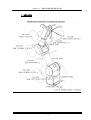

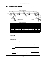


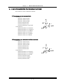


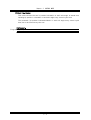
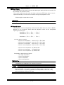
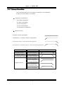
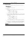

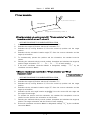
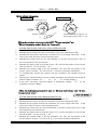


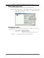
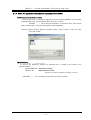
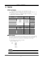
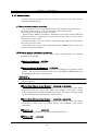
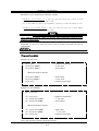


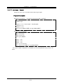
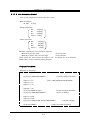
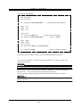
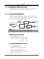

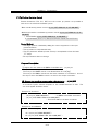
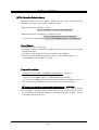

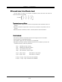

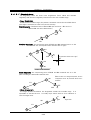
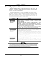
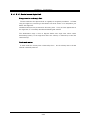
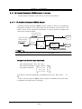


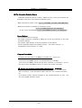


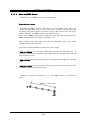

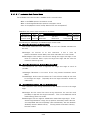
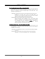
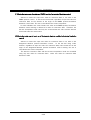

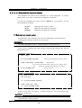
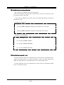

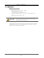


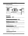
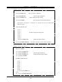
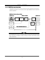


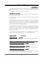
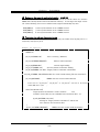
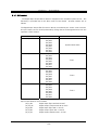

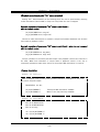
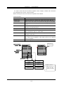
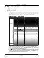
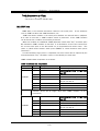

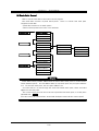
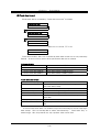

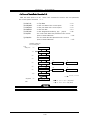
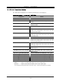
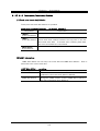
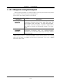
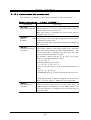

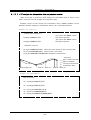
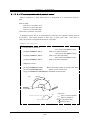

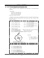
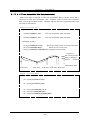
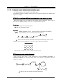


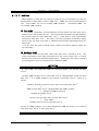

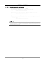
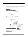


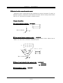

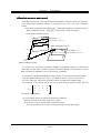

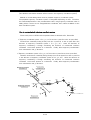
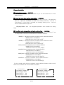

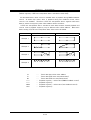

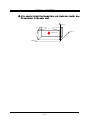
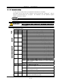
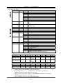


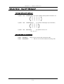


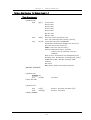


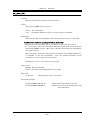
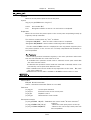

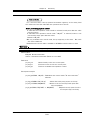

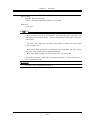


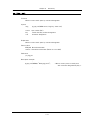
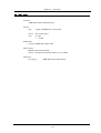
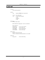
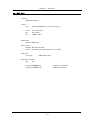


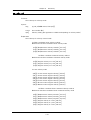

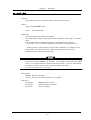


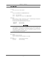
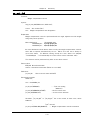
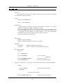
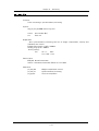


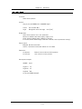
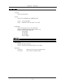
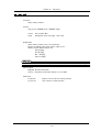
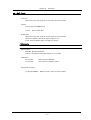
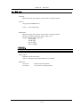


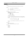
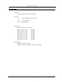
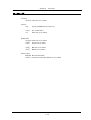


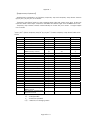

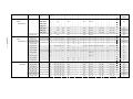
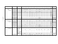
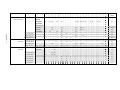

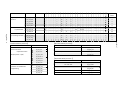
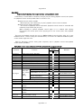


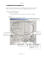

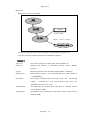

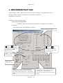


![[Script Editor basics - v1.5] 700 KB](http://vs1.manualzilla.com/store/data/005726068_1-0a14f792b169a78eb7f0605403a4865d-150x150.png)