1
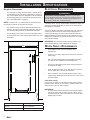
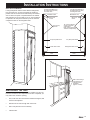
I n stall at i o n I n str u ct i o n s B u i lt - I n R e f r i g e r ato rs Part No. 100500 Rev. A Table of Refrigerator Safety........................................................................1 Design Specifications................................................................2-6 Product Dimensions.....................................................................2 Door Swing Dimensions..............................................................2 Custom Overlay Panels............................................................3-6 Installation Specifications.........................................................7-8 Tools and Parts............................................................................7 Location Requirements.............................................................7-8 Electrical Requirements...............................................................8 Water Supply Requirements........................................................8 Installation Instructions...........................................................9-14 Contents Unpack Refrigerator.....................................................................9 Anti-tip Blocking...........................................................................9 Water Line Connection..............................................................10 Plug in Refrigerator....................................................................10 Move Unit to Final Position........................................................10 Level Unit...................................................................................10 Install Custom Panels........................................................... 11-13 Anchor the Unit..........................................................................13 Installation Check List................................................................14 Service Information.....................................................................14 Refrigerator Safety What You Need to Know About Safety Instructions Recognize Safety Symbols, Words, Labels DANGER Warning and Important Safety Instructions appearing in this guide are not meant to cover all possible conditions and situations that may occur. Common sense, caution and care must be exercised when installing, maintaining or operating appliance. DANGER – Immediate hazards which WILL result in severe personal injury or death. Always contact Dacor® about problems or conditions you do not understand. WARNING – Hazards or unsafe practices which COULD result in severe personal injury or death. WARNING CAUTION WARNING – Hazards or unsafe practices which COULD result in minor personal injury or property damage. Installation Recommendations The importance of the installation of the Dacor® Built-In Refrigerator cannot be overemphasized. Installation should be done by a qualified installer. Before you begin the installation process, it is recommended that you read this entire Installation Instruction Manual. There are key details that you should take special care to observe during the installation. By reading these instructions carefully, you will make the installation process easier, problem-free and, most importantly, safe. Any questions or problems with the installation should be directed to your Dacor® dealer or the Dacor® Customer Service Department at 800.793.0093 or email customerservice@ dacorworld.com. You can also visit our website at www.dacor.com. Design Specifications Product Dimensions ◊ The depth from the front of the top grill (w/o decorator panel) to the back of the refrigerator chassis is 25 1/4” (641mm). ◊ The depth from the rear of the top grill to the back of the refrigerator chassis is 23 13/16” (605mm). ◊ The power cord is 40” (1016mm) long. ◊ The height from the top of the top grill to floor with the leveling legs in the down position is 83 3/8” (2118mm) ◊ The height from the top of the top grill to floor with the leveling legs in the fully extended position is 84 5/8” (2149mm) ◊ The chassis width from the chassis edge to the chassis edge for 42-inch is model 41 1/4” (1048mm), 48-inch is model 47 1/4” (1200mm). ◊ The overall width from the trim edge to the trim edge for 42inch model is 42 1/16” (1068mm), 48-inch model is 48 1/16” (1221mm). Door Swing Dimensions The area to the left and the right of the appliance must permit both doors to open to a minimum of 90°. Allow a minimum of 2 1/2” (64mm) space between the side of the refrigerator doors and a corner wall. NOTE: More clearance may be required if using an overlay panel or custom handles. Design Specifications Custom Overlay Panels (A) Grille Panel The decorator panels for overlay models cover the door trim for an attractive, seamless look that flows into the overall design of the room. This application is often accomplished by using three panels: the decorative front panel, a spacer panel of .10-inch thickness, and a 1/4-inch backer panel. (see page 4) H W W W (C) Non-Dispenser Freezer Panel (D) Refrigerator Panel (B) Dispenser Freezer Panel H H H2 H1 W1 W2 W Design Specifications Overlay Panel Specifications NOTES: (See Illustrations on page 3.) ◊ 42-Inch Model 48-Inch Model W Width 40 1/4” (1022mm) 46 1/4” (1175mm) H Height 8 3/4” (222mm) 8 3/4” (222mm) 16 1/4” (413mm) 18 1/2” (470mm) BACKER PANEL (A) Grille Panel (B) Freezer Dispenser Panel W Width W1 Width 2” (51mm) 2” (51mm) W2 Width 14 1/2” (368mm) 14 1/2” (368mm) H Height 69 1/8” (1756mm) 69 1/8” (1756mm) H1 Height 34 1/16” (865mm) 34 1/16” (865mm) H2 Height 48 1/8” (1222mm) 48 1/8” (1222mm) (C) Freezer Non-Dispenser Panel W Width 16 1/4” (413mm) 18 1/2” (470mm) H Height 69 1/8” (1756mm) 69 1/8” (1756mm) ◊ ◊ ◊ Use counter sink screws for attaching the backer panel to the front panel. On 42” custom panels watch location of handle mounting due to under cut of front panel. For freezer dispenser front panels, remove fountain trim and tape to the backside of the backer panel. Note recycle symbol should be visible and located at the bottom. You may want to remove any additional material on the backer panel when used in conjunction with a front panel. Remove 1/32” on thickness and 1/2” wide of material on the inside surface of the backer panel. This will help ease assembly of the panel assembly onto the door. Backer Panel Thickness 1/4” (6mm) Spacer Panel Thickness 0.100” (2.5mm) If Raised Panel is Used Overall Front Panel Thickness Not to Exceed 1 1/4” (318mm) Spacer Panel Front Decorator Panel 3/4" Max. .10 " (D) Refrigerator Panel W Width 23 1/2” (597mm) 27 1/4” (692mm) H Height 69 1/8” (1756mm) 69 1/8” (1756mm) W Width 39 1/4” (997mm) 45 1/4” (1149mm) H Height 7 3/4” (197mm) 7 3/4” (197mm) 15 1/4” (387mm) 17 1/2” (445mm) 2” (51mm) 2” (51mm) Backer Panel 1/4" SPACER PANEL (A) Grille Panel 3/4" Max. (B) Freezer Dispenser Panel W Width W1 Width W2 Width Spacer Panel .10 " 14 1/2” (368mm) 14 1/2” (368mm) 68 1/8” (1730mm) 68 1/8” (1730mm) H1 Height 34 1/16” (865mm) 34 1/16” (865mm) H2 Height 48 1/8” (1222mm) 48 1/8” (1222mm) W Width 15 1/4” (387mm) 17 1/2” (445mm) H Height 68 1/8” (1730mm) 68 1/8” (1730mm) H Height Front Decorator Panel (C) Freezer Non-Dispenser Panel Backer Panel 1/4" Side Panel Specifications If using side panels with the Dacor® Built-In Refrigerator, they will need to be 1/4” (6mm) thick. Front Rear (D) Refrigerator Panel W Width 22 1/2” (572mm) 26 1/4” (667mm) H Height 68 1/8” (1730mm) 68 1/8” (1730mm) W Width 40 1/4” (1022mm) 46 1/4” (1175mm) H Height 8 3/4” (222mm) 8 3/4” (222mm) 16 7/16” (418mm) 18 3/4” (476mm) 2 1/4” (572mm) 2 1/4” (572mm) 82 13/16" (2103mm) Side Panel (Dimensions Typ.) FRONT DECORATOR PANEL (A) Grille Panel (B) Freezer Dispenser Panel W Width W1 Width W2 Width 14 1/4” (362mm) 14 1/4” (362mm) 69 1/4” (1759mm) 69 1/4” (1759mm) H1 Height 34 5/16” (872mm) 34 5/16” (872mm) H2 Height 47 13/16” (1214mm) 47 13/16” (1214mm) H Height 3/8" (10mm) (C) Freezer Non-Dispenser Panel W Width 16 7/16” (418mm) 18 3/4” (476mm) H Height 69 1/4” (1759mm) 69 1/4” (1759mm) (D) Refrigerator Panel 24" (610mm) 1 3/8" (35mm) W Width 23 3/4” (603mm) 27 1/2” (699mm) H Height 69 1/4” (1759mm) 69 1/4” (1759mm) 2 7/16" (62mm) 2 1/2" (64mm) Toe Kick and Hinge Area Design Specifications Custom Toe Kickplate Specifications If using custom toe kickplate with your Dacor® Built-In Refrigerator, refer to the following specifications. Angled cut for thicker plates Panel thicker than 3/16" 6 1/4" 5 5/8" 15/16" Typ 4 13/16" 7/8" (A) 5/16" (A) (B) (B) 2 3/16" Typ 1 13/16" 3/4" Typ 1 1/8" Typ Cut out for Dispenser (B) (A) (B) R. 1/2" 3" 3 3/4" Allow relief here for dispenser models with panels thicker than 3/16" “C” Model 42-Inch 48-Inch Hole “A”Dia. Hole “B”Dia. Overall Length “C” 3/16” (5mm) 1/2” (13mm) 40 7/8” (1038mm) 46 7/8” (1191mm) Non-Dispenser Custom Handle Specifications Before installing the custom panel assembly, the custom handle hardware must be installed. It is recommended that handles with larger D-style pulls be used. If the screws that are used have thick heads, the screws will need to be countersunk into the panel before it is put into place. Custom Panel Door Swing Specifications The following illustrations let you see what considerations you need to make for any custom panel applications, and how they may interact with adjacent cabinets and/or countertops. Cabinet Trim 135˚ Door Opening (Top View) IMPORTANT: Dacor® advises not using single pull knobs on Built-In Refrigerator. 1/8" Door Closed 20" (508mm) 3/4" Overlay Panel 11 /4" 3/4 1" 1/2 " 1/4 " " 0" Door Open @ 135˚ Design Specifications 90˚ Door Opening (Top View) Cabinet Trim 90° Door Stop Both doors are designed to open 135°. To restrict one or both doors to a 90° opening, use the door stops supplied in this kit. 23 7/8" to Rear of Cabinet 0" 1/4" 1/2" 3/4" 1" 1 1/4" 1 1/2" 1 3/4" 2" 2 1/4" 2 1/2" 2 3/4" 3" 3 1/4" 3 1/2" Door Closed Door Panel Door Open @ 90˚ Lower Hinge Plate 1 1/4" 1" 3/4" 1/2" 1/4" 0" 3/4" Overlay Panel 90° Door Stop Door Stop Mounting Hole With the doors closed, screw a door stop into the underside of the lower hinge plate as illustrated above. Tools and IMPORTANT: Installation Specifications Parts ◊ Installer: Leave these Installation Instructions with the homeowner. ◊ Homeowner: Keep these Installation Instructions for future reference. Save these Installation Instructions for the local electrical inspector’s use. Tools needed: Make sure that you have the necessary tools and materials available for a proper installation. ◊ Phillips screwdriver set ◊ Slotted screwdriver set ◊ Torx drive screwdriver set ◊ Provide sufficient length 8’ (2.4m) to allow for a minimum of a 24” (610mm) diameter service loop of 1/4” (6mm) copper tubing and saddle valve for the water line (Do not use selfpiercing valves) Location Requirements Your Dacor® refrigerator can be recessed in an opening between cabinets or installed at the end of a cabinet run using a side panel to enclose the refrigerator. WARNING Explosion Hazard – Keep flammable material and vapors, such as gasoline, away from refrigerator. Failure to do so can result in death, explosion, or fire. IMPORTANT: ◊ Observe all governing codes and ordinances. ◊ Do not install the refrigerator near an oven, radiator, or other heat source, nor in a location where the temperature will fall below 55°F (13°C). ◊ Floor must support the refrigerator weight, more than 600lbs (272kg), door panels and contents of the refrigerator. ◊ Ceiling height must allow for side tipping radius. ◊ Location should permit doors to open fully. ◊ Location must permit the top grill to be opened. ◊ Copper tubing cutter ◊ Level - 2’ (.6m) and 4’ (1.2m) recommended ◊ Appliance Dolly able to support 700lbs (317kg) and adequate manpower to handle the weight of the appliance ◊ Various sized pliers The solid sofit or ceiling should be within 1” (25mm) above the refrigerator. It the solid sofit is higher than 1” (25mm) or one is not available, then the refrigerator must be braced to prevent tipping during use. ◊ Allen wrench set If the anti-tip blocking is need.(see “Anti-Tip Blocking”on page 9) ◊ 3/8” hex bolt nut driver or socket set IMPORTANT: To operate properly, the door must open a ◊ Crescent wrenches ◊ Cordless drill and assorted drill bits ◊ Masonite, plywood, 1/8” pressed fiberboard, cardboard or other suitable material to protect finished flooring ◊ Appropriate materials to cover and protect the home and its furnishings during installation Site Preparation minimum of 90°. For installation in a corner, a 2 1/2” (64mm) filler strip is required to ensure the 90° opening. The floor under the refrigerator is to be level with the surrounding floor. To protect the floor when moving the refrigerator, place cardboard, or preferably a carpet remnant (backing up) on the floor. Installation Specifications Electrical Requirements Rough-In Dimensions ◊ The solid sofit or ceiling should be within 1” (25mm) above the refrigerator. If the solid sofit is higher than 1” (25mm) or one is not available, then the refrigerator must be braced to prevent tipping during use. If the anti-tip blocking is need. (see “Anti-Tip Blocking” on page 9) NOTE: A clearance of 1/2” (13mm) must be maintained above the top grill in order for the top grill to be opened. ◊ ◊ A grounded 3 prong non-GFCI electrical outlet should be placed 2” (51mm) from the right side cabinets or end panel. See “Electrical Requirements” for additional information. The plumbing for the water line can come through the floor or the back wall. See “Water Supply Requirements” for more information. WARNING Electrical shock Hazard – Plug into a grounded 3prong non-GFCI outlet. Do not remove ground prong. Do not use an adapter. Do not us an extension cord. Failure to do so can result in death, fire, or electrical shock. A 115VAC, 60 Hz, 15 Amp circuit breaker and electrical supply are required. A separate dedicated non-GFCI circuit, servicing only this appliance, is required. Your Dacor® Built-In refrigerator is equipped with a 40” (1016mm) 3-prong grounded power cord, which must be plugged into a 3-prong grounding-type non-GFCI wall receptacle. Follow the National Electrical Code and local codes and ordinances when installing the receptacle. See “Rough-In Dimensions” for location of the electrical supply. IMPORTANT: A ground fault circuit interrupter (GFCI) is not recommended and may cause interruption of operation. “A” Water Supply Requirements 2” ◊ All installations must meet local plumbing code requirements. ◊ Connect to 1/4” (6mm) copper line to the house cold fresh water supply. ◊ Use a shut off valve between the refrigerator and supply. The shut off valve should be a drilled saddle valve. ◊ Do not use a self-tapping valve which reduces water flow and clogs more easily. ◊ Route the water line within 3-1/2” (89mm) of the rear wall and no higher than 3” (76mm) from the floor. ◊ Allow a minimum of 24” (610mm) dimeter service loop of copper tubing outside the wall or floor for easy connection to the water supply. Electrical 7” 4” 83 3/4” 75 1/2” Cold water supply Connect the ice maker to a cold water line with water pressure between 30 and 120 PSI. If you have any questions about your water pressure, call your utility company. IMPORTANT: 6” Water Supply Model 3” 24” Rough-In Width “A” 42-Inch 41 1/2”” (1054mm) 48-Inch 47 1/2”” (1207mm) ◊ In homes with a Reverse Osmosis water treatment system, remove the water inlet connector from the “yellow” valve and attached to the “blue” valve. Make sure the water filter bypass plug is in place. Installation Instructions Unpack Refrigerator WARNING Tip over Hazard – Refrigerator is top heavy and tips easily when not completely installed, Keep doors taped closed until refrigerator is completely installed. Use two or more people to move and install refrigerator. Failure to do so can result in death or serious injury. Anti-Tip Blocking Blocking the Refrigerator If there is a solid sofit or ceiling above the unit and the clearance is 1” (25mm) or less you will not need to block the unit. For installations with clearances of more than 1” (25mm), you must use the anti-tipping 2x4 and brackets provided. IMPORTANT: ◊ Do not remove the protective film until the refrigerator is in its operating position. 1. Uncrate the refrigerator. 2. Remove the lower shipping bolts and brackets. 3. Slide the unit off of the crate base. 4. Remove and save the lower kick plate, anti-tip brackets and mounting hardware. Soffit More than an 1” More than 1” clearance: Use the anti-tip kit provided with the shipping crate. 1. Locate and mark the 2 wall studs behind the refrigerator. 2. Mark where the “L” brackets and the 2x4 will be located and drill two 1/8” pilot holes 3. Locate proper height to clear the unit. The space between the top of the unit and the bottom of the wood block must not exceed 1/4”. 4. Secure the “L” brackets, using the provided screws, into the wall stud. 5. Align the pilot hole with the “L” brackets and secure the 2x4 with screws provided. Wall Studs 5. Place an appliance dolly under the freezer side of the refrigerator. Be sure to protect the side trims and handles. Place the corner post from the packing materials over the trims and handles as appropriate. Carefully tighten the strap. NOTE: Avoid damaging water valves and water lines in front and back of cabinet. 6. Place protective material on the floor when rolling the dolly and refrigerator into the house. Move the unit close to the built-in opening Installation Instructions Water Line Connection ◊ Before attaching the copper tubing to the unit, flush at least 2qt (1.9L) of water through the copper tubing into a bucket to get rid of any particles in the water line. Level Unit ◊ Slide the unit in place and raise the front and rear levelers until the unit touches the brackets. (Use a 3/8” socket to raise and lower the unit.) ◊ Check for leaks around the saddle valve. Do not overtighten the clamp or sleeve. This will crush the copper tubing. ◊ Check to see whether the refrigerator is level left to right, by opening the doors and place a level on top of the refrigerator frame as shown. ◊ Make connection to the refrigerator. ◊ Turn shutoff valve ON. ◊ Check for leaks, Tighten any nuts or connections (including connections at the valve) that leak. ◊ Use the leveling bolts to adjust the leveling legs until the refrigerator is level from left to right. ◊ Check to see whether the refrigerator is level from front to back, by placing the level(s) on the shelf or shelves. ◊ Use the leveling bolts to adjust the leveling legs until the refrigerator is level from front to rear. ◊ Verify that all 4 leveling legs contact the floor and support the full weight of the refrigerator. ◊ Make final check to ensure that the refrigerator is level. ◊ Install the kickplate. Plug in Refrigerator WARNING Electrical shock Hazard – Plug into a grounded 3prong non-GFCI outlet. Do not remove ground prong. Do not use an adapter. Do not us an extension cord. Failure to do so can result in death, fire, or electrical shock. 1. Verify that the switch in the top cabinet is in the OFF position. 2. Plug into a grounded 3-prong outlet. Main Power and Fahrenheit/Celsius Switches Move Unit to Final Position IMPORTANT: To prevent floor damage, make sure levelers are raised (not touching the floor) and the unit is on rollers before moving. ◊ Place top of cardboard carton or plywood under refrigerator. Remove unit from dolly. ◊ Do not remove protective film. ◊ Move the refrigerator straight back and evenly into the rough opening. Verify that the water tubing is not kinked and the power cord is not kinked. 10 Installation Instructions Install Custom Panels Panel Installation Before you begin installing panels, refer to the “Custom Panel Specifications” for overlay models and verify that you are working with the panel design called for in your installation. If you have chosen the stainless steel design, your refrigerator has been shipped complete with a finished stainless steel front. It will not be necessary to install panels or handle hardware. Be aware that panels used on refrigerators with the overlay design have the potential for coming into contact with adjacent cabinets and/or countertops when the refrigerator doors are opened. You will want to be mindful of the surrounding cabinetry and space limitations when planning for decorator panels. Refer to the 90° door stop information on page 6. Panel Installation for Dispenser Models 1. Power switch needs to be off. Switch located in machine compartment area (see User Guide). 2. Remove magnetic strip on door trim. Use of tape may be required removing the magnetic strip. 3. Remove four Phillips screws to remove door trim. (Refer to numbered illustrations for steps 4-10) 4. Remove the spill tray grille from the fountain. IMPORTANT: The weight of each panel cannot exceed 50lbs (23kg).The grille panel weight cannot exceed 10lbs (5kg). To install overlay panels, the door trim must be removed. The trim screws are hidden by a magnet backed trim molding. Remove the molding by using the adhesive side of packing tape on the magnetic backed molding to pull it away from the trim and expose the trim screws. The molding will bend at the center so that you can remove it. See illustration below. 4 5. Phillips Screwdriver Remove the two #15 Torx machine screws, which retain the stainless steel splashguard. Remove the splashguard. Pull Tape Away from Door 5 6. With a phillips screwdriver, remove the trim from the freezer and refrigerator doors. Slide the panel into the frame on the door. With the panel in position, replace the trim. Be sure that the panel is inserted completely into the channel for proper fit and alignment. Replace the trim molding by inserting the top, then the bottom into the trim channel. Release the middle and set the magnets. Remove the two #15 Torx long plastic screws that retain the fountain control panel. (Longer screws). Slide control panel down to remove. Disconnect the electrical terminals going to the fountain control panel. Tuck dispenser terminal inside to avoid interference. 6 11 insTallaTion insTRuCTions 7. Remove the four #15 Torx plastic collar screws from the fountain/escutcheon collar. Terminals Control Panel 7 8. Place the fountain/ escutcheon collar onto the backer panel. Use tape to hold in place. Stainless Steel Splashguard Spill Tray Grille CAUTION 8 9. Open the freezer door and slide panel onto the door. WARNING – Do not exceed the panel dimensions shown in the chart on page 4 for the grille panel. If the decorator panel is larger than specified, it may restrict the airflow to the compressor and condenser area, which may cause the unit to function improperly. IMPORTANT: When attaching a raised wood panel of 1/2” or thicker secure the raised panel to the back of the grille cover frame. Use 4 #8 or similar screws. Adjust Door Hinges 9 10. The holes in the fountain/escutcheon collar should line up with the mounting holes in the door panel. Reverse instructions 7 to 1 (ex. Replace the four #15 Torx plastic collar screws from the fountain escutcheon collar) 10 Check to make sure the doors are properly aligned. If not, the door hinges will have to be adjusted. Remove the two small shipping screws from the top and bottom hinge as shown below. Next, using a #25 torx screwdriver, loosen the torx head screws in the top and bottom hinge. Loosen the torx head screws only slightly, so that the door will remain in position as you adjust it. You will now be able to move the door to the left or right. Once the adjustments are made, tighten the torx head screws - do not put the shipping screws back. Installation Instructions Side Panel Installation If using side panels with the Dacor® Built-In Refrigerator, they will need to be 1/4-inch thick. Slide the panel into position and secure with screws indicated by the shaded area. A 3/16-inch spacer is required between the cabinet and side panel. A 1/2-inch thick by 10 1/4- inch tall spacer is required if the side panel extends up into the machine compartment area on the refrigerator side. 1/4" side panel fitted up to the cabinet trim (top view) on Freezer side. Backside of Unit #8-32 1/2" Screw 3/16" (5mm) Spacers 1/4" (6mm) Side Panel Freezer Side of Unit Door 1/4" side panel fitted up to the cabinet trim (top view) on Refrigerator side. Backside of Unit #8-32 1/2" Screw 1/2" (13mm) Spacers on side of machine compartment [3/16" (5mm) below the machine compartment] 1/4" (6mm) Side Panel Refrigerator Side of Unit Door Drill 3 holes through vertical frame into cabinetry where applicable. (approx. location) Anchoring the Unit After the door and side panels have been installed, and the unit has been leveled and door adjustment has been completed, you may anchor the unit to the opening. ◊ First, make sure the unit has been leveled and aligned, and the doors are adjusted. ◊ Drill three 3/16” holes through both outer trims. ◊ Drill a 1/8” pilot hole into the cabinetry. ◊ Install screws. 13 Installation Instructions Installation Checklist The importance of the proper installation of your Dacor Built-In Refrigerator cannot be overemphasized. Proper installation is the responsibility of the homeowner. IMPORTANT: To ensure a safe and proper installation, the following checklist should be competed by the installer to ensure that no part of the installation has been overlooked. Any questions or problems with this installations should be directed to your Dacor® dealer or the Dacor® Customer Service Department at 800.793.0093 or email customerservice@ dacorworld.com. You can also visit our website at dacor.com. Has the refrigerator been secured in place with the provided anti-tip blocking or is there a clearance of 1” (25mm) or less between the unit and a solid soffit? Are all leveling legs extended down to make contact with the floor? Is the unit level? Is the power cord plugged into a properly grounded dedicated 3-prong non-GFCI outlet, which had been installed in accordance with all applicable electrical codes? Is the water supply connected? Have you checked for leaks? Has the kickplate been installed properly? Are all panels attached securely and properly aligned? Have any installation/service problems been noted on the product registration card? Has the registration card been mailed? Service Information If you need service, be sure to have the model and serial numbers when you call. You’ll find these numbers on the serial number plate located on the light shield in the fresh food compartment. Contact a Dacor® authorized Servicer, a Dacor® dealer, or the Dacor® Customer Service Department at 800.793.0093 or email [email protected] 14 DANGER To reduce risk of injury or death, follow basic precautions, including the following: IMPORTANT: Child entrapment and suffocation are not problems of the past. Junked or abandoned refrigerators are still dangerous – even if they sit out for “just a few days.” If you are getting rid of your old refrigerator, please follow the instructions below to help prevent accidents. Before you throw away your old refrigerator or freezer: • Take off the doors. • Leave the shelves in place so children may not easily climb inside. Notes 15 Notes 16 Web Site: Phone: www.dacor.com (800) 793-0093 The information and images in this book are the copyright property of Distinctive Appliances, Inc. Neither this book nor any information or images contained herein may be copied or used in whole or in part without the express written permission of Distinctive Appliances, Inc. ©Distinctive Appliances, Inc. all rights reserved.