1
User's Manual
V34bis Fax-modem - AJ 2885 P
User's Manual
V34 Fax-modem - AJ 2885P
P/N 8000 601 953
Revision 01
Sales, Ma
CXR SA
Rue de
28410 A
Tel : 33
Fax : 3
Sales, manufacturing and R&D Center :
CXR SA
Rue de l'Ornette - 28410 Abondant - France
Tél 33 (0) 237.62.88.00 - Fax 33 (0) 237.62.88.01
TECHNIC
Technical support: 33 (0) 237.62.88.04
WEB Site: http://www.cxr.fr
Web site
AJ 2885 P - Page 1
User's Manual
V34bis Fax-modem - AJ 2885 P
Notice
No part of this document may be reproduced, transmitted, copied out or translated without prior
written consent of CXR SA.
All rights reserved.
Copyright 2005, CXR SA, printed in France, June 2005.
The only purpose of this manual is to provide information and installation instructions
CXR reserves the rights to improve its products and specifications without notice.
CXR has made every effort to provide the best possible quality in writing this manual but cannot
be held responsible for any damage, which could result from errors or improper description of
the equipment, its characteristics and operation.
Please read and enforce the safety instructions of the safety and installation chapters.
Head quarter:
CXR
Rue de l’Ornette - 28410 Abondant - France
Tel : +33 (0) 237 628 800 Fax : +33 (0) 237 628 801
Foreword
This document describes how to set up the CXR AJ 2885 P modem.
• Chapter 1 is to familiarize the user with the operation of a modem.
• Chapter 2 describes the installation.
• Chapter 3 describes the most common uses of a modem.
• Chapter 4 explains the operation of the modem security features and memories.
• Chapter 5 provides technical characteristics.
• Chapter 6 indicates how to solve operation problems.
Note to the reader
Users who are not familiar with the AJ 2885 P modem operation, should read the first three
chapters. Advanced users can refer directly to chapter 4 to use the advanced functions of the
modem. Whenever a problem arises, please refer to chapter 6.
The CXR Anderson Jacobson team
thanks you for purchasing an AJ 2885 modem. We hope this equipment will be to your
satisfaction, and in order to provide you with a better service, we thank you for completing and
mailing us the reply coupon enclosed with your modem. You can also find in our range of
products some ISDN adapters. Please call you distributor or CXR for information.
AJ 2885 P - Page 2
User's Manual
V34bis Fax-modem - AJ 2885 P
Important Information
Conformity Statement EC
Manufacturer name:
CXR
Manufacturer address:
rue de l'Ornette - 28410 ABONDANT – France
Product name:
AJ 2885 P
This equipment was design to comply with the ETSI – CTR.21 standard. It is intended to
connect to the Public Switched Telephone Network. However, since differences exist between
networks from a country to another or from an operator to another, this conformity does not
constitute an absolute guaranty for an optimum operation of the equipment in any situation of
use. In any case of problem, you should first contact your provider of this equipment.
The CE mark attests the conformity of this equipment to the main requirements of the R&TTE
1999/05/CEE European community :
For the user’s safety, in compliance with the 73/23/EEC European Directive, as per
EN.60950 standard
For electromagnetic compatibility, in compliance with the 89/336/EEC European
Directive, as per EN.61000-6-1 and EN.61000-6-3 standards.
CXR states that this equipment is manufactured in compliance with the Annex II of the
1999/05/EEC European Directive.
Safety Instructions
The following accesses are referenced as SELV (Safety Low Voltage] in conformity with
EN.60950 standards:
•
5 VDC Input of the AJ 2885P-xxV desktop unit
•
48 VDC Input of the AJ 2885 P - xxC desktop unit
•
Terminal: V24 - RS232 data port
The following access are referenced as TNV (Telecommunication Network Voltage] in
conformity with EN.60950 standards:
•
Tel-Line : PSTN access as a TNV-3 interface,
•
Lease : Leased line access as a TNV-2 interface.
Desktop AJ 2885 P - xxV:
The wall mount power supply adapter is the main switching element. Thus this plug must be
installed close to the equipment and provided easy access.
To totally disconnect the equipment from the supply source we recommend you disconnect the
power cord from the mains wall outlet. In order to comply with the safety regulations, it is
imperative to use the accessories (power supply and cables) provided with the equipment.
When access to the inside of the modem is necessary, it is imperative to disconnect the power
adapter from the mains outlet.
Desktop AJ 2885 P – xx i :
The power cord is the main switching element. Thus the mains outlet must be installed close to
the equipment and provided easy access. In order to comply with the safety regulations, it is
imperative to use the accessories (power supply and cables) provided with the equipment.
When access to the inside of the modem is necessary, it is imperative to disconnect the power
cord from the mains outlet. This is a Class 2 product as shows the
symbol close to the mains
socket; its earth connection is for functional purpose only.
AJ 2885 P - Page 3
User's Manual
V34bis Fax-modem - AJ 2885 P
Desktop AJ 2885 P – xxM :
The power cord is the main switching element. Thus the mains outlet must be installed close to
the equipment and provided easy access. In order to comply with the safety regulations, it is
imperative to use the accessories (power supply and cables) provided with the equipment.
When access to the inside of the modem is necessary, it is imperative to disconnect the power
cord from the mains outlet. This is a Class 1 product; its earth connection must be carefully
provided through its original mains cord.
Rack mountable card AJ 2885 P - xxR
The power switch located on the rear of the chassis is the only switching element, thus it must
be fully accessible. The connection to the mains is achieved through the cable equipped with a
male-grounded plug. Extract the card from the chassis when maintenance or servicing is
required
For safety reasons, any operation on the equipment and particularly opening the desktop
enclosure must be carried out by maintenance person qualified by CXR.
The equipment must imperatively be returned to CXR in any case of anomaly, fall, loss of
performance, water exposure, power supply damage, power or line cord damage, …
Environment
The AJ 2885 P is designed for residential or light industrial use within the following
environmental conditions:
•
Storage Temperature
0 to 70 °C
•
Operating Temperature:
0 to 45 °C
•
Hygrometry:
0 to 90% without condensation
•
Class:
IP40
•
Flammability:
UL94-V0
Place the equipment in a area well suited for its good operation and its
•
Equipment must not be exposed to excessive solar radiation
•
Equipment must not be in contact with water. It must not be used near a water reserve or
in a wet location.
•
Equipment must be installed on a plane and horizontal surface, without vibration.
•
Make sure the area is clean, dry and exempt of dust
•
Make sure that nothing could obstruct the air vent of the product, and that no small size
part (screw, staple, clip, …) could get into it.
•
Always disconnect the mains connection before any operation (move, connecting other
equipment, …) on the equipment. The mains cord must be taken from the socket; any
effort on the cord could induce damages and risk of electrical shock.
Use
The AJ 2885 modem is intended to connect to the Public Switch Telephone Network and to a
leased line in voice frequency mode (300 to 3400 Hz) It was designed to comply with the ETSI
CTR.21 standard.
The AJ 2885 P modem provides the modes of connection as per the following ITU-T standards:
•
Data modes : V34, V32Bis, V32, V22Bis, V22, V23, V21
•
Error correction and data compression : V42, V42Bis, MNP4, MNP5
•
Fax mode : Group 3, Class-2, V17, V29, V27Ter, V21
The AJ2885P connects to a data terminal equipment through its terminal interface :
AJ 2885 P - Page 4
User's Manual
•
V34bis Fax-modem - AJ 2885 P
V24-V28 or RS232
•
V11 compatible with X21 and V35 though configuration jumpers (except FT model)
•
Data rates : 300 to 115,200 BPS in asynchronous mode, and 1200 to 33,600 BPS in
synchronous mode.
Correct Disposal of the Product - Recycling
In compliance with the European rules for separate collection systems and
Waste of Electric and Electronic Equipment, this marking shown on this
product indicates that it should not be disposed with other household
wastes at the end of working life. To prevent possible harm to the
environment or human health from uncontrolled waste disposal, please
separate this from other types of wastes an d recycle it responsibly to
promote the sustainable reuse of material resources.
Household users should contact either the retailer were they purchased this product, or their
local government office for details of where and how they can take this item for environmental
safe recycling.
Business users should contact their supplier and check the term and conditions of the purchase
contract. This product should not be mixed with other commercial wastes for disposal.
AJ 2885 P - Page 5
User's Manual
V34bis Fax-modem - AJ 2885 P
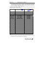
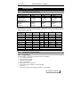
Product range
The AJ 2885 modem has various options:
• Dial-up
• Leased line
• Group III fax
• Stand alone or rack
• LCD front panel
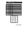
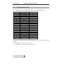
These different versions are summed up in the following table. The names in the first column
will be used throughout the manual to indicate when these options apply.
Metallic enclosure.
LCD version
Versions :
Options :
2 / 4 wire leased line
Dial backup and real time clock
14.4 KBPS – Cl.2 G.3 Fax
V11 – X21 / V35 interface
V23 / Bell 202 T 1200/1200 4 wire
mode
LCD and 3 keys front panel
remote action and alarm relays
Firmware in Flash memory
Metallic enclosure & internal
110/230 V Mains
Plastic enclosure & internal
110/230 V Mains
Metallic enclosure & internal 48
Vdc converter (*)
Plastic enclosure and wall
mount 110/230 mains supply
Plastic enclosure and internal
48Vdc converter (*)
Card for the AMS4/16 chassis
Stand alone version
Rackmount version
FT
FPx
SD/SM
BPx
BDx
-
-
SDM
BPM
BDM
-
-
SDI
-
-
-
-
SDN
BPN
BDN
FTV
FPV
-
-
-
-
FPC
-
-
-
-
FPR
-
BPR
-
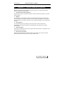
Options :
Tropicalization : Special treatment that allows the modem to be used in strong climatic
environment.
Internal DC converter (*) : the AJ2885P modem can also be provided with a CD converter
for supply voltages of 12, 24 and 36 Vdc.
AJ 2885 P - Page 6
User's Manual
V34bis Fax-modem - AJ 2885 P
AJ 2885 features
The AJ 2885 is a modem for the professional user. It encompasses a number of features that
place it above the rest. It includes features such as:
• Configuration through front panel LCD and key pad: for synchronous application, the 2885
SDV can be fully set up from its user friendly front panel.
• Busy-Out: Whenever modems are pooled, a faulty modem will lock-up the rest. The busyout, standard in the CXR modems lets the PBX pass onto the next modem without
upsetting the system.
• Line Quality Testing: The modem can test a line at every call. If it finds it below standard, it
will hang-up and retry up to 5 times transparently to the user. This guarantees that you have
the most reliable connection every time on any type of infrastructure.
• BERT: The modem can perform simple Bit Error Rate Tests between two CXR modems to
qualify the digital transmission of data.
• ITU V.13: Half duplex operation.
• 10 Configurations
• Unattended Automatic Dial Backup: If ever your Leased Line fails, the AJ 2885 will back-up
onto the dial-up network. Not only that, it will continue to monitor the Leased Line until it is
operational and switch back automatically. This is called Intelligent Look-Back. Back-up
may be allowed and disabled over week-day and week-end periods.
• Password Security: To change configuration of the modem, 2 levels of password security
are provided - User & Supervisor.
• Connection Security: 4 levels of security are provided:
Answerback, i.e. where the far modem asks the calling modem for a password,
transparently to the user.
Pass Through Access, i.e. where the far modem asks the user for a password.
Automatic Modem Password Access, i.e. same as before but for synchronous
operation.
Call back, i.e. the far modem asks for a password from the calling modem and
hangs up. The far modem associates a telephone number with the password and
calls back the original calling modem.
• 5 different Statuses:
Modem Configuration.
Line, e.g. Xmit/Rcve levels, signal quality etc.
Line Error Statistics, e.g. for MNP or V42, the number of bad characters, bytes
frames etc.
Leased Line Statistics, e.g. connection & idle time etc.
Dial-Up Statistics, e.g. same as leased line with directory information etc.
This is but a short list. For full details, consult the Command Set Manual.
AJ 2885 P - Page 7
User's Manual
V34bis Fax-modem - AJ 2885 P
Contents
1.
INTRODUCTION ......................................................................................................10
1.1.
1.2.
1.3.
THE MODEM .......................................................................................................10
THE MODEM-FAX ................................................................................................10
CALLING MODES DIALING.....................................................................................10
1.3.1.
1.3.2.
1.4.
1.5.
1.6.
2.
Calling Mode ............................................................................. 10
Answering Mode ........................................................................ 10
LEASED LINE ......................................................................................................11
PROTOCOLS .......................................................................................................11
MEMORY ............................................................................................................11
INSTALLATION........................................................................................................13
2.1.
2.2.
2.3.
STAND ALONE VERSION ......................................................................................13
RACKMOUNT VERSION ........................................................................................14
SWITCH AND JUMPER SETTINGS ..........................................................................16
2.3.1.
2.3.2.
2.3.3.
2.4.
3.
Dumb mode : J6 jumper ............................................................ 16
SW5 switch................................................................................. 16
V11 – V28 terminal interface : J9 – J21 jumpers ...................... 16
POWER-UP SELF-TEST ........................................................................................17
OPERATION.............................................................................................................18
3.1.
3.2.
4.
SYNTAX OF AT COMMANDS .................................................................................18
FIRST DIALOGUE .................................................................................................18
FRONT PANEL OPERATION ..................................................................................19
4.1.
OPERATING MODES ............................................................................................19
4.1.1.
4.1.2.
4.1.3.
4.1.4.
4.1.5.
4.2.
CONFIGURATION THROUGH FRONT PANEL LCD AND KEYPAD ................................22
4.2.1.
4.2.2.
4.2.3.
4.2.4.
5.
Operating modes........................................................................ 19
The Front Panel......................................................................... 19
The Push Button......................................................................... 20
Configuration Select .................................................................. 21
Factory configuration detail...................................................... 21
The four LEDs indicate the state of the modem......................... 22
LCD displays ............................................................................. 22
Three keys operation.................................................................. 23
Example ..................................................................................... 24
CONFIGURATIONS .................................................................................................26
5.1.
5.2.
5.3.
5.4.
5.5.
5.5.1.
5.5.2.
FACTORY CONFIGURATION ..................................................................................26
SELECTING THE MODEM SPEED ...........................................................................26
RATE AND CONNECTION MODE SELECTION ...........................................................28
ASYNCHRONOUS OR SYNCHRONOUS MODE :........................................................30
CONFIGURATION OF THE ASYNCHRONOUS MODE :................................................30
Error correction and data compression: ................................... 30
Flow control: ............................................................................. 31
AJ 2885 P - Page 8
User's Manual
5.6.
5.7.
5.8.
5.9.
5.10.
5.11.
CONFIGURATION OF THE SYNCHRONOUS MODE ................................................... 31
AUTOMATIC DIALING DIRECTORY ......................................................................... 32
LEASED LINE ...................................................................................................... 32
V23 AND BELL 202 T MODES ON LEASED LINE ................................................... 33
SAVING USER CONFIGURATIONS ......................................................................... 34
V54 - MAINTENANCE .......................................................................................... 34
5.11.1.
6.
V34bis Fax-modem - AJ 2885 P
AT command operation.............................................................. 34
SECURITY AND MEMORY...................................................................................... 36
6.1.
6.2.
6.3.
6.4.
PRINCIPLES ....................................................................................................... 36
THE PHONE DIRECTORY ...................................................................................... 36
ANSWERBACK SECURITY .................................................................................... 37
CALLBACK SECURITY .......................................................................................... 37
6.4.1.
6.4.2.
6.5.
7.
Automatic callback..................................................................... 37
Dial number request callback. ................................................... 38
INACTIVITY PASSWORD ....................................................................................... 38
SPECIFICATIONS.................................................................................................... 39
7.1.
7.2.
LINE SIDE CHARACTERISTICS .............................................................................. 39
AUTOMATIC CALL & ANSWER .............................................................................. 39
7.2.1.
7.2.2.
7.2.3.
7.3.
7.4.
SERIAL INTERFACE ............................................................................................. 40
FAX-MODE ......................................................................................................... 40
7.4.1.
7.4.2.
7.4.3.
7.4.4.
7.4.5.
7.5.
Originating................................................................................. 39
Answering a Call........................................................................ 40
Connection - Disconnection....................................................... 40
Automatic Call and Answer ....................................................... 40
Transmission Modes .................................................................. 40
Operating Mode ......................................................................... 40
Service Class 1 Command Set.................................................... 40
Service Class 2 Command Set.................................................... 41
GENERAL CHARACTERISTICS .............................................................................. 41
8.
TROUBLESHOOTING ............................................................................................. 42
9.
APPENDIX A - V24 SIGNALS ................................................................................. 43
9.1.
9.2.
9.3.
9.4.
9.5.
V24 – V28 INTERFACE ....................................................................................... 43
V11-V35 INTERFACE:......................................................................................... 44
DIAL LINE CONNECTOR: RJ11 CONNECTOR ......................................................... 47
LEASED LINE CONNECTOR : RJ11 CONNECTOR .................................................... 47
ALARM RELAY CONNECTOR ................................................................................. 47
10.
APPENDIX B - COUNTRY SPECIFIC INFORMATION ........................................... 48
11.
APPENDIX C – GENERAL CONDITIONS OF GUARANTY.................................... 49
AJ 2885 P - Page 9
User's Manual
1.
V34bis Fax-modem - AJ 2885 P
Introduction
This chapter is to familiarize the user with the operation of a modem. Note: <CR> indicates that
the user must press the return key after a command sequence.
1.1.
The modem
A modem is a device that allows two terminals (DTE, PC...) to communicate via a
telecommunication line (phone line).
The data is converted by the modem into electrical signals adapted to the telecommunication
network. This conversion is called modulation and demodulation.
Various conversion techniques have been developed to speed-up the data flow. The different
speeds are particular to each type of modulation: 300 bps in V21, 2400 bps in V22bis, 14400
bps in V32bis, and 33600 bps in V34.
1.2.
The modem-fax
A fax device transmits scanned images via the telephone network.
In addition to traditional fax machines, the fax modem also allows transfer of computer data
such as:
• ASCII files from a text processor,
• PCX or TIF files from a graphic editor, etc.
The Fax mode operation is controlled by a fax software which:
• Converts files to T4 format (fax graphic format),
• Transmits and receives faxes,
• Supervises fax modem operation.
Supervision of the fax modem is carried out by a standard protocol: "Asynchronous Facsimile
DCE Control Standard", Class 1 Service - TR 29.2188 or Class 2 Service - TR 29.2388.
The computer equipped with a fax modem will be able to transmit and receive fax in Group III
mode:
• At about one A4 page per minute,
• In fine or standard resolution.
See chapter 5 for the list of modem class 1 and 2 commands.
1.3.
Calling modes - dialing
The modem can be in 2 modes:
Send or calling,
Receive or answer.
1.3.1.
Calling Mode
The modem switches to originate mode when the dial command: ATD 37487126 is sent
(example number).
The calling modem then waits for the remote modem to respond.
1.3.2.
Answering Mode
The modem switches to answer mode when it detects ringing on the phone line.
AJ 2885 P - Page 10
User's Manual
V34bis Fax-modem - AJ 2885 P
The answer is carried out automatically if the command ATS0 = 2 was sent to the modem by
the local PC. A training sequence is then initiated. A training sequence is the hand-shake
sequence between modems to establish a communication link. It establishes speed, modes...
1.4.
Leased line
A leased line is a permanent communication link dedicated between two modems. This kind of
link is used for:
• High usage,
• Secure communications,
• Privately managed networks.
The leased line, can be a:
• 4-Wire type where there is:
1 transmit pair,
1 receive pair.
• 2-Wire type where:
the same pair of wires is used for transmit & receive.
For a leased line, a modem is designated:
• Originating modem (ORIGINATE or MASTER),
• The other as the answering modem (ANSWER or SLAVE).
Modems in leased line mode always try to connect when power is on, in order to provide
permanent a link.
The AJ 2885 modem can establish leased line connections in the following speeds:
V22
1200 bps
V22bis
2400 bps
V32
9600 bps/4800 bps
V32bis
14400 bps/12000 bps
V34
33600 bps down to 2400 per steps of 2400 bps
In case of failure on the leased line, the AJ 2885 modem performs automatic switch-over to the
dial-up PSTN. It then monitors continuously the leased line until it can connect again on leased
line. The AJ2885P modem is provided with an internal real time clock and calendar, to disable
dial backup when the link is not of use and then optimise the PSTN cost .
1.5.
Protocols
Two types of protocols can be used to improve communication performance between two
modems:
• Error correction:
MNP4 or V42 detect errors which occurred during data transmission, and either correct
them or re-transmit the data.
•
Data compression:
MNP5 or V42bis compress the data and thus transmit at a higher effective speed.
These two types of protocols improve efficiency and reliability of a connection.
1.6.
Memory
Beyond these basic principles, the modem offers other functions, aimed at improving
performance and ease of use.
These functions are controlled via the memory (S-Registers) of the modem, and are available
via the extended AT command set.
AJ 2885 P - Page 11
User's Manual
V34bis Fax-modem - AJ 2885 P
These functions are described in chapter 4 of this manual.
Some of the extra functions are:
• Storage of phone numbers,
• Forced V24 signals,
• Exchange of a password between two modems ("Answer Back"),
• Pre-qualification of the telephone line,
• Storage of user modem configuration.
AJ 2885 P - Page 12
User's Manual
V34bis Fax-modem - AJ 2885 P
2.
Installation
2.1.
Stand alone version
Package Contents:
Before installing your modem, check all these items are present:
• One AJ 2885 modem
• One RJ11 phone cable
• Power supply or 48V cable for SPC version
• Leased line RJ-11 cable, except for STV and FTV versions
• A CD-ROM that includes
• The AT and V25bis command reference manual
• This User manual
• Software (as an option)
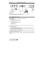
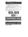
Connections:
Connect your modem as shown on the following diagram:
Classic stand alone enclosure:
V24
230 Vac
access
RJ 11 - PSTN
(*)
LL
RJ 11 - LL
(*) Wall mount power supply.
Only the power module provided with the unit must be used.
Metallic enclosure: provides 3 RJ11 sockets:
Standard SDM version:
230V
LL
AJ 2885 P - Page 13
User's Manual
V34bis Fax-modem - AJ 2885 P
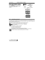
SDM version + alarm relay option:
230V
ALARM
or
Industrial
Equipment
LL
Power On:
When the modem is connected, switch the power switch to the "On" position.
(*) Power supply DC adapter or Power supply cable.
2.2.
Rackmount version
Package Contents:
Before installing your modem, check all these items are present:
• One AJ 2885 card
• One RJ11 phone cable (as an option)
• A leased line RJ-11 cable (as an option)
• A CD-ROM that includes
• AT command set reference manual
• User manual
• Software (as an option)
If you ordered the busy out function, check that the K3 option is available. This function forces
the line to be active when there is:
• A faulty power supply,
• No answer to a call after N rings (N is set by the S20 register). This maybe due to a nonconnected data terminal (DTR/108 absent).
• N successive ineffective connection sequences (N is set by the S20 register). This maybe
due to a bad connection to the telephone line.
This option is particularly useful for line pooling applications, and in case of fault, incoming calls
are switched to another modem in the pool.
Your AJ2885 board provides an interface to the AMS controller board that is an option to your
AMS16 rack. Refer to the controller card manual for managing the AJ2885 modem through the
controller card.
AJ 2885 P - Page 14
User's Manual
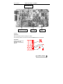
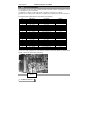
V34bis Fax-modem - AJ 2885 P
K3-J8 : Busy-out
J9-J21 : V11 / V28
J6 : DUMB
SW5
Sandwich
Installation:
See rack operation manual to install your modem.
Find an empty location in the rack and insert the AJ 2885 card into its card guide.
Connection :
Connect your modem from
the rear of the rack,
according to the following
diagram:
LL
AJ 2885 P - Page 15
User's Manual
V34bis Fax-modem - AJ 2885 P
Power On:
Inserting the modem card connects it to the power supply of the rack. Power-on is carried out by
the power switch located at the rear of the rack.
Make sure the front panel screws are well fixed onto the chassis so that the modem card is well
connected to the AMS back plane.
2.3.
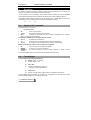
Switch and Jumper settings
2.3.1.
Dumb mode : J6 jumper
When set in the ON position, this jumper disables the AT and V25Bis commands. This may be
interesting for synchronous connection, or to protect the configuration of the modem set for
answer mode.
2.3.2.
SW5 switch
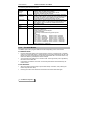
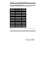
This switch does not apply on the FT model.
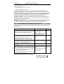
The following data terminal signals can be forced ON through these four switches :
Switch
Signal
SW5-1
DTR
On position effect
The 108 – DTR signal from the terminal is ignored
AT Command
AT &D0
SW5-2
CD
The modem provides a permanent 109 – CD signal
AT &C0
SW5-3
DSR
The modem provides a permanent 107 - DSR signal
AT %D0
SW5-4
CTS
The modem provides a permanent 106 – CTS signal
AT %C0
2.3.3.
V11 – V28 terminal interface : J9 – J21 jumpers
This switch does not apply on the FT model.
The J9-J21 jumpers set the data terminal interface for :
•
•
V24-V28 or RS232 : jumpers in the 1–2 position
V11 (X21 / V35) : jumpers in the 2–3 position
In this case, jumpers J19, J20 and J21 connect a 560 Ohm impedance on the V11
receivers the the TD, XCLK and DTR signal respectively.
These jumpers are described in a dedicated appendix at the end of this manual.
AJ 2885 P - Page 16
User's Manual
2.4.
V34bis Fax-modem - AJ 2885 P
Power-up self-test
When the modem is turned on, an automatic self-test is performed, which tests:
• Its stored memory
• Its program memory
• Its data processing unit
• Its data memory
The test lasts a few seconds and ends with a series of:
• Different tones if the test is ok,
• The same tone if a failure is detected. This failure is stored in the S19 register or detailed by
the ATi7 command. See chapter 6 "Troubleshooting".
The self test result is displayed on the front panel LCD of the 2885 SDV version.
AJ 2885 P - Page 17
User's Manual
3.
V34bis Fax-modem - AJ 2885 P
Operation
The modem operation is usually controlled through its terminal interface that connects to a
computer or a terminal, and through a set of AT commands.
On the computer (a PC for example), start a communication software such as the Windows
HyperTerminal (HyperTerminal and Windows are trade marks of their respective owners).
The AJ2885 modem adapts automatically to the speed (300 to 115,200 BPS) and format of
characters sent by the computer when it receives the following characters :
AT
3.1.
or
at
Syntax of AT commands
Commands are built as follows :
AT xxxxxxx <RC>
•
AT
•
•
xxxxxx
is the actual command and parameter
<RC>
complete the command line. This character corresponds to the ‘Carriage
return’ or ‘Enter’ key f the keyboard.
is the command prefix
The following commands do not comply with this syntax :
•
•
•
A/ or a/
+++
^Z^Z^Z
to repeat the last command
to escape from connect data mode to local command mode
to escape from connect data mode to remote command mode
Modem sends back an answer when a command is competed :
•
OK
if the command is successfully completed
•
•
ERROR
CONNECT
example
in case of error in the command line
(or another message) in case of action command
to place a call for
The AT and V25Bis reference manual provides the detail of the commands.
3.2.
First dialogue
You can then try the following commands :
AT<RC> (<RC> or ENTER )
Modem answer : OK
ATI3 <RC>
Answer: AJ 2885P-FPVF Rev-5.10*
* example of product identification
AT&S <RC>
Answer : modem sends multiple pages of configuration and status.
This first dialog being completed, the chapter 5 for configuration and the reference manual
provide detailed description of the modem commands.
AJ 2885 P - Page 18
User's Manual
V34bis Fax-modem - AJ 2885 P
4.
Front panel operation
4.1.
Operating modes
This chapter describes the operation of the six
LEDs front panel version of 2885 modem.
4.1.1.
Operating modes
The modem can operate in one of the four following modes:
1. IDLE MODE:
• The modem enters the idle mode after powering up if it passes its power-up self test. Beeps
announcing the end of the test can be heard unless the speaker is turned off (see
corresponding command).
• From this mode, the modem will enter in command mode by receiving a command from the
DTE, or in ONLINE mode if an automatic call is initiated from the front panel, or if a call is
received when the modem is configured to answer calls.
2. COMMAND MODE:
• The modem enters the command mode when it receives a recognized command. In this
mode, commands are interpreted and executed. (Configuration set up - automatic call
request...). The modem also enters in command mode when it recognizes an escape
sequence in the data when in an on-line rude.
3. ONLINE MODE:
• The on-line mode starts, when detecting a carrier signal from a remote modem or when
dialing is successfully completed.
4. TEST:
• The test mode is selected when in a command mode using appropriate test commands.
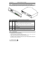
4.1.2.
The Front Panel
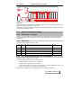
The front panel of the modem has six red LEDs and one push button.
The different LEDs indicate the state of the modem and the status of the self test sequence.
DTR
DSR/RI
CD
TXD
RXD
108
125/107
109
103
104
LINE
MODE
AJ 2885 P - Page 19
User's Manual
V34bis Fax-modem - AJ 2885 P
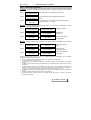
The following table list these functions:
LED
DTR (Data
Circuit
108
Function
Indicates that the data terminal equipment connected to the
Terminal
modem is ready for data communication.
Ready)
On if DTR is set or fllashing if DTR-108 is not set.
Bad Eprom checksum during self test.
DSR/RI (Data 107/125 Flashes when an incoming ring is received (125/RI). Remains
Set Ready/Ring
lighted permanently when connecting. On leased line, the
Indicator)
Originate modem flashes 10 times per second and the Answer
one 4 times per second, when waiting for carrier. Also bad
RAM causes flashing of light during power up test.
109
Indicates that the remote modem's carrier signal has been
CD (Carrier
Detect)
received by the modem. In test mode, this light will flash if the
test is negative. Also on if bad non volatile ram checksum
during power up test.
Flashes as data is transmitted by the modem.
TXD (Transmit 103
Data)
RXD (Receive
104
Flashes as data is received by the modem.
LINE
-
Indicates the mode of connection:
Permanent: Leased Line
Flashing: PSTN or V23 half duplex
Off: Command Mode
Equally a sign of bad DSP during power up test.
PSTN
Off: 300 bps
Flash 1 Time = 1200 bps
Flash 2 Times = 2400 bps
Flash 3 Times = 4800 bps
Flash 4 Times = 9600 bps
Flash 5 Times = 12000 bps Flash 6 Times = 14400 bps
Flash 7 Times = 16800 bps Flash 8 Times = 19200 bps
Flash 9 Times = 7200 bps
Flash 12 Times = 21600 bps
Flash 13 Times = 24000 bps Flash 14 Times = 26400 bps
Flash 15 Times = 28800 bps Flash 16 Times = 31600 bps
Lighted permanent = 33600 bps
Data)
4.1.3.
The Push Button
The MODE push button programs different functions depending on the current mode.
IN COMMAND MODE:
• Performs automatic dialing of the number stored in memory or holds the line in originate
mode if no number was stored, or starts answering if rings were detected on the line. The
length of the press is signaled by a single flash of the DSR LED. The PSTN number may
have been dialled by the telephone set for example.
• A two-second push holds the line in answer mode. The length of this push is signaled by
two flashes of the DSR LED.
• If the button is pressed for more than 10 seconds (three flashes of the DSR LED), the
modem resets.
IN ON-LINE MODE:
• When the modem issues a beep to report a dial backup connection, then pressing the
button stops the alarm beep.
• Pressing the button once disconnects the modem and selects idle mode again.
AJ 2885 P - Page 20
User's Manual
4.1.4.
V34bis Fax-modem - AJ 2885 P
Configuration Select
Holding MODE for more than 10 seconds will initiate a hardware reset.
If the switch is still pressed after some beeps are heard at power-up, the modem will enter
configuration mode.
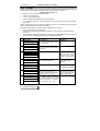
The front panel LEDs DTR, DSR, CD and LINE indicate which configuration the user can select.
There are listed in the following table:
DTR
0
DSR
0
CD
1
LINE
1
0
1
0
1
0
1
1
1
1
1
0
0
0
1
1
0
0
0
1
1
0
0
0
1
1
0
1
0
1
1
1
0
0
0
0
0
Configuration
Factory configuration "0" async dial configuration
(AT&F0)
Factory configuration "1" sync 2WLL configuration
originate (AT&F1)
Factory configuration "2" sync 2WLL configuration
answer (AT&F2)
Factory configuration "3" V25bis HDLC dialer (AT&F3)
Factory configuration "4" V25bis BSC dialer (AT&F4)
User configuration "0" (AT%M0)
User configuration "1" (AT%M1)
User configuration "2" (AT%M2)
User configuration "3" (AT%M3)
User configuration "4" (AT%M4)
Each of the configuration will stay on for 2 seconds while the MODE button is pressed.
Releasing the button will select the new configuration, and this configuration will be loaded after
power up. Immediately after the power up test (after the beeps), the LEDs will indicate which
configuration is loaded for 2 seconds.
4.1.5.
Factory configuration detail
The following parameters differ from the factory 0 configuration.
• Factory 1 : E0 Q1 &D0 %D2 &C1 %C1 &R0 @A0 &M1 &L2 *LG0 *M1
• Factory 2 : E0 Q1 &D0 %D2 &C1 %C1 &R0 @A0 &M1 &L2 %O0 *LG0 *M1
• Factory 3 : E0 %D2 &C3 %C3 &R0 @V3 %B1 @A0 &M1 *LG0 *M1
• Factory 4 : E0 %D2 &C3 %C3 &R0 @V4 %B1 @A0 &M1 *LG0 *M1
These configurations may change without notice. Please check on your modem.
AJ 2885 P - Page 21
User's Manual
4.2.
V34bis Fax-modem - AJ 2885 P
Configuration through front panel LCD and keypad
This chapter describes states of the front panel lights and operation of the LCD and keypad.
4.2.1.
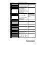
The four LEDs indicate the state of the modem
LED
DSR/Ri
Circuit Function
107/125 Flashes when an incoming ring is receiving (125-Ri).
On leased line, the Originate modem flashes 10 times per second and
the Answer one 4 times per second, when waiting for carrier.
When
ON when DSR is activated, when the modem is off hook and when
connected.
109
Indicates that the modem is connected to the remote one, i.e. remote
carrier is detected.
103/104 Flashes as data are received and transmitted by the modem.
108
Indicates that the data terminal equipment connected to the modem is
ready for data communication flashes if DTR-108 is not active.
CD
DATA
DTR
4.2.2.
LCD displays
The LCD displays two lines of 16 characters:
It displays results of the self test after power on.
The main menu displays successively states of the modem (connection, speed, DTE interface
status) and branches to configuration and dialing sub-menus.
Theses menus are described on the menu map as a separate document.
Three keys are used to pass between menus: down ↓ key accesses next item in a list, enter ↵
key validates a choice or branches to a sub-menu, and left ← key comes back one step to the
main menu with no effect on last choice.
AJ 2885 P - Page 22
User's Manual
4.2.3.
V34bis Fax-modem - AJ 2885 P
Three keys operation
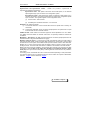
↵ ENTER : This key validates the displayed choice or option, according to the following
examples:
Case 1
PRESS ENTER FOR
CONFIG CHANGE
Enter branches to the configuration sub-menus.
Case 2
CHANGE ?
VISUAL DISPLAY
Enter branches to the AT display parameter submenus.
Case 3
COMMAND ECHO
ON > OFF
Enter selects the new value of the parameter located
on the right of the « > » symbol.
↓ DOWN : This key displays next item of the menu, i.e. next menu, or parameter or value,
according to the following examples:
Case 1
SELECT
CONFIGURATION?
↓
STORE
CONFIGURATION ?
Case 2
COMMAND ECHO
ON CHANGE?
↓
QUIET
OFF CHANGE ?
Case 3
COMMAND ECHO
ON > OFF
↓
COMMAND ECHO
ON > OFF
Displays next menu.
Displays next
parameter.
Displays next value of
the parameter.
← LEFT : This key comes back one step to the previous menu, according to the following
examples:
Case 1
CHANGE ?
MODEM OPTION
←
AJ 2885 SDVF
REV 5.01
Comes back to main
menu.
Case 2
COMMAND ECHO
ON CHANGE ?
←
CHANGE ?
VISUAL DISPLAY
Comes back to
configuration menu.
Case 3
COMMAND ECHO
ON > OFF
←
COMMAND ECHO
ON CHANGE ?
Leaves the parameter
unchanged.
From the main menu, LEFT ← key is a multiple action key depending on the modem
configuration and connection status:
•
•
•
•
•
•
•
•
During training, left key aborts the connection and restores command mode,
In on line mode, left key disconnects,
In idle mode, if the modem is configured in leased line mode, left key initiates a leased line
training,
In idle mode when incoming rings are detected, left key initiates answer mode (acts as an ‘ATA’
command),
In idle mode when the modem is configured in dial up mode (i.e. not in leased line mode), left key
initiates a calling mode connection. The modem dials the first automatic number found in the
phone book, or just hangs up in calling mode if any (acts as an ‘ATDS’ or ‘ATD’),
In leased line mode with dial backup option set, during training on lease line, left key initiates dial
backup,
During dial backup with alarm beep, left key stops beeping,
During dial backup without alarm beep, left keep aborts the dial line connection and starts
training on leased line.
AJ 2885 P - Page 23
User's Manual
4.2.4.
V34bis Fax-modem - AJ 2885 P
Example
How to store a phone number in the phone book as would this AT command:
•
•
•
•
•
AT&Z3:CXR:FOX:33237:::A
Number 3 in the phone book (range 0 to 99),
« CXR » is the name field,
« FOX » is the password field,
LINK and CONFIGURATION fields are both left blank,
« A », attributes means this number is dialed from the front panel or from the DTE interface
(DTR, 108-1).
NOTA : Please refer to the AT command reference manual for more details on the phone book
fields and usage (see AT commands: &N, &Z, DS).
While editing the number, the modem keeps modification in its memory:
• You may stop editing, and restart later,
• This memory is not saved: modification will be lost in case of reset by ATZ command or
power lost,
• To save memory and make modification permanent, you must validate the last menu of the
number editing: « PRESS ENTER TO SAVE NUMBER MEMORY ».
#
1
On display
Press the key
PRESS ENTER FOR
↵ to access configuration menus,
then ↓ to display :
Comments
CONFIG CHANGE
2
CHANGE?
↵ to access phone number editing
sub-menus
PHONE NUMBERS
3
CHANGE? P00:O
↓ to access number 3
00 already exists in this
example. Look at the
name on line 1 an the
number on the second
line,
123456
4
CHANGE? PO3 :
↵ to start editing number 3
03 is empty in this
example
5
P03:--NAME--?
↵ to edit the NAME field
↓ would access to the
PASSWORD next field
6
PO3:--NAME--
↓ three times to displays « C »
character. Then leave ↓ pressed
until you get a « C » again
Note that the ? symbol
is gone. Note the cursor
position while editing
_
7
PO3:--NAME-C
AJ 2885 P - Page 24
↵ to validate this first character,
the cursor moves on the right.
Press ↓ to get the « X », then ↵,
then ↓ to get the « R », then ↵
User's Manual
V34bis Fax-modem - AJ 2885 P
#
On display
Press the key
8
PO3:--NAME--
↵ no character is displayed on the ↵ validate a field on a
cursor: ENTER key validates this blank cursor
field and initiate next field editing
CXR_
Comments
9
PO3:--PASSWORD--?
Just like steps 5 to 8, press :
↵ once to start editing,
↓ to get « F », then ↵ (« F- »)
↓ to get « O », then ↵ (« FO- »)
↓ to get « X », then ↵ (« FOX- »)
↵ to validate « FOX », as the
password and access to the next
field of this number
10
PO3:--NUMBER--?
Again like previous steps, press:
↵ once to start editing,
↓ to get « 3 », then ↵ (« 3- »)
↓ to get « 3 », then ↵ (« 33- »)
↓ to get « 2 », then ↵ (« 332- »)
↓ to get « 3 », then ↵ (« 3323- »)
↓ to get « 7 », then ↵ (« 33237- »)
↵ to validate « 33237 »,
11
PO3:--LINK--?
↓ to get next field
Note that dialable digits
are available as well as
control character. Refer
to the dial command
ATD in the reference
manual
NONE
12
PO3:--CONFIG--?
↓ to get next field
NONE
13
PO3:--ATTRIBUTE--
↵ to edit attribute field
NONE
14
PO3:
NONE
↵ to validate this choice
Note the attribute on the
first line
AUTO CALL > ON ?
15
PO3:
A
↓ to display next attribute
DIAL OUT > ON ?
16
PO3
A
↓ 4 times to pass other attributes
and display next menu
PASSWD ACCS>ON ?
17
SAVE MEMORY
↵ to save these changes in
permanent memory, or
← to ignore and return to
configuration menu (step 2)
without saving memory
AJ 2885 P - Page 25
User's Manual
5.
V34bis Fax-modem - AJ 2885 P
Configurations
This chapter describes commonly used configurations through the AT command set: These
commands may be used as part of software drivers for example. The same configuration can
be achieved through the LCD and keypad front panel. Refer to the LCD menu description in
chapter 2.5.
5.1.
Factory configuration
This configuration applies when the modem is first powered on, or after complete reset by the
following commands:
AT&W255 <CR>
Answer : OK
ATZ <CR>
Answer : OK
This configuration is designed for most common applications and has the following
characteristics:
DTE - V24:
Normal CD, DTR,
DSR and CTS forced on.
Automatic answer S0 = 2
Automatic hunt: V34, V32bis, V32, V22bis, V21 and V23 modes
Error correction and data compression: V42bis and MNP automatic mode (*M2)
Flow control: RTS/CTS (*LG2)
This configuration can be modified for a specific application. The following examples describe
the most common applications.
5.2.
Selecting the modem speed
Introduction :
Modem provides two interfaces : the DTE interface connected to the terminal, and the
DCE one to the remote modem. This is described by the following picture of a point to
point connection :
Terminal
Modem
DTE
Terminal
Modem
DCE
DCE
DTE
Modem adapts these two interfaces that may work at different rates : these are DTE and DCE
speeds. The DTE speed applies on the terminal interface rate (between the modem and the
terminal) while the DCE speed applies on the line rate (between both modems).
Controlling modem speed : in default factory configuration, modem is set for automatic mode
also said Autobaud, which satisfies most cases of use. In this case, modem defines the DCE
speed upon the DTE speed which was automatically detected whe the last AT command was
received.
AJ 2885 P - Page 26
User's Manual
V34bis Fax-modem - AJ 2885 P
Modem speed can be controlled thanks to the following commands.
Asynchronous and Synchronous modes : modem can provide a synchronous or
asynchronous interface to the terminal
Synchronous mode : DTE speed is the same as the DCE speed, i.e. the terminal
speed might change upon connection from configuration speed.
Asynchronous mode : DTE speed does usually not depend on DCE speed, it is a
constant rate interface. The terminal speed does not change from configuration speed
upon connection. The opposite applies on two configuration cases :
(1)
in direct mode : *M0 command
(2)
in disabling the constant DTE modem : *C0 command
Autobaud : this features provides :
(1)
an automatic detection of the terminal data format and speed when receiving AT
commands,
(2)
an automatic adaptation of the connection (DCE) speed to the speed lower or equal
to the terminal one as to avoid its overflow.
V32Bis and V34 : these modes of connection support the same speedfrom 4.8 to 14.4 KBPS.
The @OM command selects the desired mode which is especially suitable for leased line
connection.
Modulation – DCE speed : the @M command selects the connection (DCE) speed when the
Autobaud feature is off (parameter different from @A1)
Buffering and flow control : in asynchronous mode and especially when the DCE speed is
lower than the DTE speed, modem can buffer data received from the terminal in order to adapt
the data rate to a lower speed. The AJ2885 modem provides a buffer of about 1000 characters.
Modem can run a flow control process when this buffer is about to get full in order to stop the
sending terminal.. The same buffer and feature is available in the modem to terminal direction.
Buffers and flow control are available in normal mode (*M1) and with error correction and data
compression (*M2 and M3). On the other hand, modem is a transparent channel in direct
mode (M0) and in synchronous mode (&M1) : buffering and flow control are then not possible in
both modes.
The flowing picture summarizes the action of these commands depending on their parameters.
This assumes that the last AT commands were sent to the modem at a speed of 38400 BPS,
and were : AT@An and then eventually AT@Mn :
AJ 2885 P - Page 27
User's Manual
V34bis Fax-modem - AJ 2885 P
CONFIGURATION PARAMETER (38,400 BPS)
CONNECTION RESULT
Autobaud
Async / Sync Mode
DCE sped
DCE speed
DTE speed
@A1 : ON
&M1 : Sync
Do not care
Do not care
33600
33600 (1)
@A2 : DTE
&M1 : Sync
Do not care
@M15: 28800
28800
28800 (1)
@A0 : OFF
@A1 : ON
&M0 : Async
*M1 : normal
Do not care
33600
38400 (2)
*M2 : auto
*M3 :
exclusive
@A1 : ON
&M0 : Async
*M0 : direct
Do not care
33600
33600
(3)
@A2 : DTE
&M0 : Async
*M1 : normal
@M4 : 9600
9600
38400
(4)
@A0 : OFF
*M2 : auto
*M3 :
exclusive
@A2 : DTE
&M0 : Async
*M0 : direct
@M4 : 9600
9600
9600
(5)
@A0 : OFF
Remark :
(1)
The synchronous mode parameter &M1 is dominating : DTE speed depends on the
connection speed. It may also vary during connection in case of retrain or fall back
negotiated with the remote modem for example.
(2)
Except for direct mode (*M0), Autobauding (@A1) is dominating : DCE speed
depends on the terminal DTE speed. The default factory configuration is based on
this configuration.
(3)
Direct mode parameter (*M0) is dominating : DTE speed change to the DCE speed
upon connection. Any speed change should be avoided in asynchronous mode since
the DTE terminal could not adapt to any further speed change.
(4)
Autobauding is either limited to the DTE speed detection (@A2) or disabled (@A0) :
DCE connection speed can be set up independently thanks to the @M parameter.
DTE terminal speed remains unchanged in asynchronous mode (constant DTE
speed).
(5)
Again Autobauding is either limited to the DTE speed detection (@A2) or disabled
(@A0) : the @M parameter sets the DCE connection speed independently from the
DTE speed. But, DTE terminal speed becomes the DCE speed upon connection
because of direct mode (*M0). Again, any speed change should be avoided in
asynchronous mode since the DTE terminal could not adapt to any further speed
change.
5.3.
Rate and connection mode selection
The AJ 2885 provides several solutions to determine the mode of connection.
Selecting connection mode for speeds of 2400 to 19200 BPS : the modem can connect
these speeds in V34 mode or in older V22, V22Bis, V32Bis or V32 is modes. The AT
@OM command selects the wanted mode of connection This command should be left as
@OM3 for automatic mode adaptation since the V34 mode is designed to recognise V32 /
V32Bis remote modems during the handshake.
Autobaud : the modem recognises automatically the speed and the data format of the
terminal when it sends an AT command. If the 'full' autobaud is active - AT @A1 - then the
modem will adapt the connection rate to the nearest lower connection speed. This is the
AJ 2885 P - Page 28
User's Manual
V34bis Fax-modem - AJ 2885 P
default factory configuration. The autobaud must be changed to select a special speed. It
can be limited to the DTE autobaud - AT @A2 - which means that the modem still
recognises the terminal data format and speed but does not change the connection rate.
Or it can be disabled - AT @A0 - which means that both the DTE data format and speed,
and connection mode are selected by Commands.
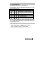
The following picture lists all connection modes on the first row, and the configuration in full
autobaud and limited or disabled autobaud.
Rate - modulation
Modem autobaud : AT@A1
DTE speed / AT command
DTE autobaud : AT@A0 or
AT@A2
AT command
300 - V21
300 / -
@M0
1200T,75T - V23
Modem can not be autobaud
@M10
75R,1200T - V23
Modem can not be autobaud
@M11
1200 - V22
1200 / AT @OM2
@OM2 @M1
2400 - V22 Bis
2400 / AT @OM2
@OM2 @M2
4800 - V32
4800 / AT @OM2
@OM2 @M3
9600 V32
9600 / AT @OM2
@OM2 @M4
7200 - V32 Bis
V32Bis fall down speed
@OM2 @M9
12000 - V32 Bis
V32Bis fall down speed
@OM2 @M5
14400 - V32 Bis
V32Bis fall down speed
@OM2 @M6
2400 - V34
2400 / @OM3
@OM3 @M2
4800 - V34
4800 / @OM3
@OM3 @M3
7200 - V34
V34 fall down speed
@OM3 @M9
9600 - V34
9600 / @OM3
@OM3 @M4
12000 - V34
V34 fall down speed
@OM3 @M5
14400 - V34
V34 fall down speed
@OM3 @M6
16800 - V34
V34 fall down speed
@OM3 @M7
19200 - V34
19200 / @OM3
@OM3 @M8
21600 - V34
V34 fall down speed
@OM3 @M12
24000 - V34
V34 fall down speed
@OM3 @M13
26400 - V34
V34 fall down speed
@OM3 @M14
28800 - V34
V34 fall down speed
@OM3 @M15
31200 - V34
V34 fall down speed
@OM3 @M16
33600 - V34
>= 38400 / @OM3
@OM3 @M17
Notes :
V34 mode on lease line should be better used without the V8 preamble. This can be
achieved by the command AT @OM1 instead of AT @OM3.
AJ 2885 P - Page 29
User's Manual
V34bis Fax-modem - AJ 2885 P
The status page 3 details all information on DTE and modem speeds, data format, parity,
synchronous or asynchronous mode (answer to the AT&S3 command).
5.4.
Asynchronous or synchronous mode :
The AJ 2885 distinguishes the command and the connection modes :
The command mode is defined by the AT @V command : asynchronous AT (@V1),
asynchronous V25 Bis (@V2), V25Bis HDLC (@V3), V25 Bis BSC (@V4) or disabled
(@V0).
The connection mode is defined
synchronous (&M1).
5.5.
by the AT &M command : asynchronous (&M0) or
Configuration of the asynchronous mode :
The following features apply on asynchronous connection mode.
5.5.1.
Error correction and data compression:
The modem is set in default factory configuration in automatic mode so that it can negotiate the
best protocol with the remote modem.
A flow control should be configured in asynchronous mode to avoid loss of received data.
The following commands apply :
Command
Function
*M0
direct mode, no protocol. The modem is
transparent to the transferred data. No
flow control is possible. The XON.XOFF
flow control is passed over the line.
*M1
Normal, no protocol. The modem buffers
transferred data. Flow control can be
RTS-CTS or XON XOFF.
*M2
Automatic. The modem tries to negotiate V42
or MNP modes
*M3
Exclusive. The modem only accepts
connection in the configured protocol.
*T
Protocol type : MNP (*T1), V42 (*T2),
automatic (*T3).
*G
Error alarm : the internal high speaker may
beep when it detects an errored packet in the
received data flow (*G0 : disable, *G1 :
enable).
&M0
Selects the asynchronous connection mode.
AJ 2885 P - Page 30
User's Manual
5.5.2.
V34bis Fax-modem - AJ 2885 P
Flow control:
Through Xon-Xoff : :
AT *LG1
generates a local Xon-Xoff,
AT *LR1
answers to the local Xon-Xoff
These commands are the original AJ commands. For compatibility with standard
general purpose modems the following command may be used : AT &K4
Through RTS-CTS :
AT *LG2
generates a CTS flow control
AT * LR2
answers to the RTS flow control
AT %C1
sets the CTS signal for flow control
AT&R1
sets the RTS signal for flow control
The *LG and %LR commands are the original AJ commands. For compatibility with
standard general purpose modems the following command may be used : AT &K3
5.6.
Configuration of the synchronous mode
AJ2885 modem provides synchronous connection in transparent mode, i.e. the same speed
applies on both DCE and DTE interfaces.
The following parameters should be adjusted for synchronous connections:
Command
&M1
*M
&X
Function
Selects the asynchronous connection mode.
0.
Direct mode. The modem is transparent to the transferred data.
Transfer delay is the lowest possible.
1.
Normal mode. The modem buffers bytes and re-synchronises bit to
the receive and transmit clock whenever possible.
0.
Internal clocks. The modem generates the clocks on V28 interface
pin 15 (pin 13 and 15 in V11 interface)
1.
External clock. The modem uses the terminal clock provided on V28
interface pin 24 (pin 11 and 24 in V11 interface). This clock must be
well adjusted to the connection mode rate.
2.
Slave clock. The modem synchronises from the received carrier and
provides these clocks on V28 interface pin 17 (pin 12 and 17 in V11
interface).
Note : some synchronous terminals sends permanent data even when the modem are not
connected. To prevent the modem to interpret these data as configuration command, it can be
set in dumb mode by the AT @V0 command, or by the X1 jumper.
(1) The &Xn parameter defines the transmit clock behaviour. A typical modem connection
sets one modem for internal clock and the other one in slave mode.
AJ 2885 P - Page 31
User's Manual
(2)
V34bis Fax-modem - AJ 2885 P
Whenever the DTE terminal issues the clock should the modem be set for external clock
(&X1). Frequency accuracy of the DTE clock must be compatible with the modulation.
In case the terminal may issue a permanent data flow even out of connection could the
DUMB mode be set to avoid any spurious commands or escape to command mode
sequences. Either set the DUMB jumper on the modem board or use the @V0 command.
When DUMB mode is set by the @V0 command then coming back to command mode
must be achieved by restoring the factory default configuration in pressing the front panel
button during power-up : the use of the DUMB mode jumper (J6) may be an easy
alternatve. The escape to command mode sequences may be disabled by resetting the
S12, S26 and S43 registers.
(3)
5.7.
Automatic dialing directory
The AJ 2885 has a non volatile memory that allows the user to store frequently used numbers.
Each phone number can have a name and control sequence associated. So instead of
remembering every number, the user can type in the recipient name, thus greatly easing the
task of making a connection.
The following example shows how to store a number, name and control sequence at location 3
of the directory memory.
Dialing a direct line, send the command:
ATDT36062424 <CR>
Dialing via a PABX, send the command:
ATDP0W36062424 <CR>
Storing a number in the directory (number 3), send the command:
AT&Z3:NAME:CONTROL:P0W36062424:::A <CR>
Show directory contents, send the command:
AT&N <CR>
Dialing from the directory:
• The ATDSn command dials the stored telephone number specified by n where n is 0 to 99.
• By CCITT 108/1 operation. The modem autodials a stored number when an off-to-on
transition of the DTR occurs. The modem disconnects when an on to off transition of the
DTR occurs. AT&D1 command select the dialing mode of the DTR signal.
• By the phone number name by the ATD$name command.
5.8.
Leased line
A leased line is a permanent analogue telephone connection between 2 sites. Therefore
connection is started with a direct training, i.e. without dialling.
Depending on the selected configuration, the following commands are sent to the modem.
(See reference manual for a description of these commands).
Configuration
2-wire line
4-wire line
Dial back up
1234 back up dial number
Recovery lookback
AJ 2885 P - Page 32
Originating modem
AT&L1%O1&W <CR>
AT&L2%O1&W <CR>
AT%U1
AT&Z:::1234:::A <CR>
AT%L1&W <CR>
Answering modem
AT&L1%O0&W <CR>
AT&L2%O0&W <CR>
AT%U1
S0=1
AT%L1&W <CR>
User's Manual
V34bis Fax-modem - AJ 2885 P
After this leased line configuration is saved by the AT&W command, the modem will start
training on leased line if :
•
it is reset by ATZ or by a power restart,
•
the front panel button is pressed.
For V34 mode of connection, better disable the V8 preamble by the command : @OM1
Automatic Dial Backup : the master or Originate modem is in charge of initiating the dialup
connection if case of leased line failure. Modems issue alarm beeps, set the backup 117 signal
and flash the DSR front panel led once the dialup connection is on. AJ2885P modems has an
embedded real time clock and calendar to disable dial backup connection outside working
week-day and week-end periods as to optimise the cost if the dialup connections.
Leased line look back : modems check for leased line recovery when in dial backup from the
S56 timer (in minutes). Look back is continuous and safe through a specific handshake as to
avoid ineffective retrains on leased line.
Permanent link on dialup line : a leased line like connection can be performed over dialup line
by setting S61 register to 1 (ATS61 = 1). This special mode does not comply with dialup
requirements : it is the user’s responsibility to use this mode on a private line only.
5.9.
V23 and Bell 202 T Modes on Leased Line
AJ2885P modem provides several V23 – BELL202 modes on leased line as summarized by the
following picture :
Type of connection
AT Command
Model
Classical 1200 / 75 V23 mode : on a 2 or 4 wire line, 1200 BPS sender modem:
full duplex link at 1200 BPS one way (@M11 modem @A2@M11&R1
to @M10 modem) and 75 BPS the other way.
1200
BPS
receiver
modem: @A2@M10&R1
All
Reversing 1200/75 V23 mode : the same mode can @A2 @M10 (or @M11)
be reversed through RTS signal control.
&R2
All
@M10 or @M11 command may be used since the
transmission mode depends on the RTS signal.
1200 / 1200 half duplex : this mode does not provide @A2 @M10 &R3 S26=10
the 75 BPS return channel, and applies on 2 or 4 wire
lines. Reversal is under RTS signal control.
All
1200 / 1200 full duplex : a full duplex FSK link on a 4 @A2 @M10 &R1 @OT1
wire line only.
BP ant BD
1200 / 1200 half duplex or carrier controlled mode or
Master – Slave mode : the same mode may be used
for multi-point or master- slave link. Master modem is
set for permanent transmission while slave modem
transmission is under RTS control.
Maître : @A2 @M10 &R1
@OT1
Esclave : @A2 @M10 &R3
@OT1 S26=30
The reversal delay is as fast as 30 ms which is
adjusted by the S26 register (in ms)
DTE interface signal in half duplex configuration :
AJ 2885 P - Page 33
BP and
BD
User's Manual
•
•
•
V34bis Fax-modem - AJ 2885 P
transmission is controlled by RTS : &R2 or &R3 parameter
Transmission acknowledgement is provided by CTS : %C1 parameter
Carrier detection (remote modem signal) is provided by CD : &C1 parameter
Half duplex reversal delay : this delay is set by the S26 register
•
•
expressed in Nx10 ms for connection without 75 BPS return channel (case 2 and 3 of the
previous picture) with a minimal value of 8 i.e. 80 ms
expressed in Nx1 ms for 1200/1200 full duplex connection (case 5 of the previous picture)
with a minimal value of 30, i.e. 30 ms. This mode applies on AJ2885P-Bxx models only.
The sending modem starts the S26 timer when the RTS signal rises, and sets the CTS signal
when the S26 timer is complete. This delay corresponds to the remote modem synchronization
time.
Bell 202 T : Bell 202 specific frequencies are used thanks to the B1 command.
5.10.
Saving user configurations
The AJ 2885 modem can store up to 5 user configurations.
The AT&Wn command saves the current configuration in non-volatile memory (n = 0 to 4). This
configuration is saved even when the modem is turned off. The modem will load the last saved
user configuration at power-up.
5.11.
V54 - Maintenance
The AJ 2885 modem provides V54 loop test functions.
The A terminal can monitor the following tests :
• Analogue local loop or B3: the A modem connects on its own carrier. The A terminal can
check characters it sends are well returned. The good operation of the A modem is tested.
• Remote digital loop or B2 : the B modem sends back all characters received from the line.
The A terminal can test the entire link to the remote modem.
A
A
B
B
5.11.1. AT command operation
The status page 10 lists all V54 test features ( command AT&S10 )
♦
B 3 : local analogue loop : the A modem is in local command mode. The local loop may
be started by the following commands :
♦
AT&T1 : simple loop. The modem connects and sends a CONNECT xxxx message. All
characters sent by the A terminal are sent back after modulation.
♦
AT&T8 : in the same kind of local loop the A modem sends and checks automatically test
characters. The error counter is displayed at the end of test.
♦
End of test : the test ends at the test timeout defined by S18, or by entering an escape
sequence ( '+++' )and an AT&T0 command
♦
Front panel LED: the CD led is on when the modem is connected, DSR led stays off.
♦
Example :
A
AJ 2885 P - Page 34
A
User's Manual
V34bis Fax-modem - AJ 2885 P
Boucle 3
AT&T1 <RC>........................................ start the test
CONNECT 19200 ................................ Connect message
ABCDE................................................. characters sent by the terminal
+++....................................................... escape to command mode
OK
AT&T0.................................................. End of test command
♦
♦
Note: the connection status ( AT&s8 ) page can be displayed during the test after an
escape to command mode.
B 2 : remote digital loop : modems are connected before starting the test.. the remote
loop on the B modem is initiated from the A modem by the following commands :
♦
AT&T6 : simple loop. The A terminal checks returned characters. The connection must be
done without any error correction protocol ( AT*M1 )
♦
AT&T7 : same loop with automatic character sending and checking by the A modem. It
displays the error counter at the end of test. The connection must be done without any
error correction protocol ( AT*M1 )
♦
End of test : the test ends at the test timeout defined by the S18 register, or by entering an
escape sequence ( '+++' ) and an AT&T0 command.
♦
Front panel LED: on the B modem, the DSR led flashes and the CTS signal is dropped
during the test.
♦
Example :
A
A
B
B
Connection at 19200bps
B2
+++
OK ......................................................... escape to local command mode on
modem A
AT&T6
OK ......................................................... requests a remote digital loop to B
modem
ABCDE .................................................. characters issued by the A terminal are
sent back by the B modem
+++
OK
AT&T0 ................................................... End of test
OK
ATO ....................................................... Return to connected mode and
reactivate the data link between the A
and B terminals.
AJ 2885 P - Page 35
User's Manual
V34bis Fax-modem - AJ 2885 P
6.
Security and memory
6.1.
Principles
The modem contains three types of memory:
The FLASH-EPROM, where factory configuration is stored permanently,
The RAM, where the modem configurations are stored temporary,
The NVRAM where semi-permanent data is stored even when the modem is turned off.
The first time your modem is turned on, or after a complete reset, these three memories are
identical and set to the default factory configuration.
The AT&Wn command saves the current configuration in the non-volatile memory, (n = 0 to 4)
or activates a factory configuration for the next reset (n=5 to 9).
For example :
AT &W0
save and activate the current user’s parameters in bank 0
AT &W5
activates factory configuration bank 0 for next reset, with no change on the
other user’s configuration banks.
The last stored user configuration will be loaded automatically on next power-up.
These memory operations are shown on the following diagram:
PROM
NV-RAM
Factory
configuration
Stored
configuration
AT&W255
AT&W
AT&F
Active
configuration
AT%m or
Power-up
RAM
Memory reset
AT&W255
Memory store
AT&W0 to AT&W4
Loading of a factory configuration without loosing the stored AT&F0 to AT&F4
memory
Loading the user configuration
AT%M0 to AT%M4
6.2.
The phone directory
Up to 100 phone numbers can be stored in the modem's non-volatile memory, to be used by the
automatic dialler.
Save a number
AT&Z0:Directory::11:::A
This command saves automatically the directory in non-volatile memory
Dial a number
ATDS0 <CR>
Display the directory
AJ 2885 P - Page 36
AT&N <CR>
User's Manual
6.3.
V34bis Fax-modem - AJ 2885 P
Answerback security
This security mode is controlled by the answering modem, and depends on a password
exchange which authorizes a modem connection, i.e.:
Calling
modem
ATDxxx
Answering
modem
Training
"AC24Y"
(for example)
ring
ENQ ()
"AC24Y"
control process
If the answerback matches the one stored in memory within two seconds after an ENQ code
was sent by the answering modem, access is granted.
Otherwise the modem disconnects automatically.
To store the answerback code, see the following example. The password can be up to 12
characters long.
Store answerback (for example: AC24Y)
AT&A:AC24Y:AC24Y <CR>
To disable answerback security
AT&A:: <CR>
6.4.
Callback security
6.4.1.
Automatic callback
This security mode is controlled by the
answering modem.
It sends a password and then calls back
the telephone number associated with that
password.
See %SA and %SB commands in the
reference manual.
Example:
HERE
N 3132
THERE
N 4142
ATS0=2
AT%SB1
ATS0=2
AT%SA1
AT&Z3:HERE:CALLB1:3132:::CD
ATD4142
Calling
Training
Password?
« call B1 »
Disconnecting
Calling (3132)
Training
Password ?
« Call B1 »
Modems are connected
This double security guarantees password and localization of the calling modem.
AJ 2885 P - Page 37
User's Manual
6.4.2.
Dial number
callback.
V34bis Fax-modem - AJ 2885 P
request
The remote user may provide the callback
number after password control.
Example:
HERE
N 3132
THERE
N 4142
ATS0=2
AT%SB1
ATD4142
ATS0=2
AT%SA1
AT&Z3:ICI:MOBILE:::
Dialing
Training
Password?
« MOBILE »
Callback number ?
3132
Disconnect
Dial (3132)
Training
Modems are connected
6.5.
Inactivity password
The modem asks for a password when no data passes through it for a presented delay. If this
password matches the operator or supervisor password stored in memory then the modem will
reconnect otherwise it will drop the line.
S32: number of minutes of inactivity that will start the password request.
S96: number of seconds that the modem will wait for the password.
AT%ST 0/1: number of password trials (0: one trial / 1: three trials).
AT%In: inactivity is detected if:
n=0: no detection, i.e. feature is disabled.
n=1: detects transmitted data inactivity.
n=2: detects received data inactivity.
n=3: detects both received and transmitted data inactivities.
AT%PS: SUPER:SUPER: stores the supervisor password, (SUPER as an example).
AT%PO: OPE:OPE: stores the operator password (OPE as an example).
AJ 2885 P - Page 38
User's Manual
V34bis Fax-modem - AJ 2885 P
7.
Specifications
7.1.
Line side characteristics
Mode
Receiver sensitivity
Carrier detection:
Open threshold
Close threshold
Transmission level:
Nominal
Maximum
Minimum
Switched network
- 43 dBm
2-wire leased line
- 33 dBm
4-wire leased line
- 26 dBm
< - 48 dBm
> - 43 dBm
< - 38 dBm
> - 33 dBm
< - 31 dBm
> -26 dBm
- 10 dBm
- 8 dBm
- 16 dBm
- 14 dBm
0 dBm
- 16 dBm
- 14 dBm
0 dBm
- 16 dBm
AJ2885P (except FTV model) provides transmit levels higher than –10 dBm : it is under user’s
responsibility to avoid these levels on the public network, and use them on private lines only for
special applications. Maximum received level is –10 dBm only : some higher received level may
induce a loss of performance.
Recommendations
V22 bis
V22
V21
V23
Call/Answer
Speed Bps
Xmit 0
Xmit 1
Received 0 Received 1
Call
Answer
Call
Answer
Call
Answer
Call
Answer
2400
2400
1200
1200
300
300
75
1200
9600
14400
33600
1200
2400
1200
2400
1180
1850
450
2100
1800 Hz
1800 Hz
Adaptive
1200
2400
1200
2400
980
1650
390
1300
2400
1200
2400
1200
1850
1180
2100
450
V32
V32 bis
V34
7.2.
Automatic call & answer
7.2.1.
Originating
2400
1200
2400
1200
1650
980
1300
390
Automatic dialling or calling by the originating modem is initiated by:
• "AT" or V25bis commands
• Push button on front panel
• DTR 108/1 being enabled
• Pulse or tone dialing.
Tone recognition occurs when there is:
• A dial request (public network or private exchange).
• A busy line.
• The call monitoring by the internal high speaker can be disabled.
AJ 2885 P - Page 39
User's Manual
7.2.2.
V34bis Fax-modem - AJ 2885 P
Answering a Call
When the modem is set in answer mode, it will go off hook after 2 rings (if the command
ATS0=2 is sent). This is in conformity with CCITT V25bis recommendation.
7.2.3.
Connection - Disconnection
In calling mode, the modem will automatically recognize the remote modem modulation type
and adapt correspondingly.
It will disconnect only if:
• The carrier is lost,
• No carrier tone is detected within 35 to 90 seconds,
• No data activity has occurred for the selected period of time dictated by the Inactivity Timer.
7.3.
Serial interface
The V24 serial interface of the modem conforms to the DCE specifications. A straight ribbon
cable is all that is needed to connect to the DTE port of your computer or terminal. The serial
port will automatically recognize DTE speeds up to 115200 bps. This is called auto-bauding.
Both asynchronous and synchronous (except FSK : V21, V23) modes with internal or external
clock are supported.
7.4.
Fax-mode
7.4.1.
Automatic Call and Answer
See 5-2
7.4.2.
Transmission Modes
The modem provides the ability to send and receive faxes at speeds up to 9600 bps.
The following modulations are supported:
ITU-T
V21
V27 ter
V29
V17
7.4.3.
Speed Bps
300
2400 / 4800
7200 / 9600
12000 / 14400
Carrier (Hz)
1650 – 1850
1800
1700
1700
Operating Mode
In fax mode, the modem support the following standards:
• Group III Fax, EIA 578 class 1 and class 2 compatible,
• CCITT T4 - T30 recommendations.
7.4.4.
Service Class 1 Command Set
The following AT commands control the operation of a class 1 modem/fax:
+FCLASS
Service class identification and control
+FTS
Stop transmission and wait
+FRS
Receive silence
+FTM
Transmit mode
+FRM
Receive mode
+FTH
Transmit T30 command mode
AJ 2885 P - Page 40
User's Manual
V34bis Fax-modem - AJ 2885 P
+FRH
Receive T30 command mode
+FCERROR Error code
7.4.5.
Service Class 2 Command Set
The following AT commands control the operation of a class 2 modem/fax:
+FCLASS
Service class identification and control
+FMDL
Fax-modem model
+FMFR
Fax-modem manufacturer
+FREV
Fax-modem checkup
+FBUG
Frame report
+FAA
Automatic answer
+FBOR
Data bit order
+FDCC
Fax-modem capability selection
+FDIS
Capability initialization for transmission
+FLID
Identification selection of the fax-modem
+FCON
Remote fax detection
+FCIG
Identification of called subscriber by CIG
+FCSI
Identification of called subscriber by CSI
+FTSI
Identification of calling subscriber by TSI
+FDTC
Called fax return capability - DCS frame
+FDCS
Discussed capability for process - DCS frame
+FHR
Content of received frame
+FHT
Content of transmitted frame
+FBUF?
Buffer state
+FDT
Fax message transmission
+FPTS
Page transmission result
+FDR
Fax message reception
+FCFR
Reception mode confirmation
+FPTS
Remote reception status
+FET
End of page status
+FHNG
End of procedure status
+FAXERR Error code
7.5.
General characteristics
Dimensions :
Length: 260 mm,
Width: 170 mm,
Height: 35 mm.
Weight: 0,7kg.
External power supply module: 230V/50Hz.
Power consumption: 25mA.
Operating temperature: 0 to 50°C.
Relative humidity: 0 -> 90% non-condensing.
AJ 2885 P - Page 41
User's Manual
8.
V34bis Fax-modem - AJ 2885 P
Troubleshooting
Problem:
This chapter lists most modem operating problems.
Problem
No tone when
modem is turned
on
Single and
continuous tone
when modem is
turned on
Check
Connection to the mains On/Off switch in On position Power supply
of the rack and fuse of the card (rack version), DTR indicator on or
flashing
Send commands:
AT&W255 <CR>
ATZ <CR>
Then restart the modem to see if the same continuous tone is heard.
See Ati7 section below.
Modem does not
Flashing of the TXD indicator when sending characters. No flash:
answer commands check V24 cable. Flashes: <CR> command:
AT&S4 <CR>
and check for a long flash of TXD indicator. Long flash: check V24
cable.
Modem answers
Try to dial an outside line using the ADT command. Make sure that
"NO DIAL TONE"
you select a valid telephone number and dialling mode (P-Pulse, TTone). Listen to the internal speaker to hear the normal dial tone is
heard. If not check the line connection.
Modem refuses to Check for any blacklisting:
dial
AT&NB <CR>
(see reference manual) Turning the modem off and on resets the
blacklist.
ATI7 command:
Check the answer to the ATI7 command. It provides a clear message in case of self detected
problem.
ATI7 Response
BAD ROM
Code EPROM checksum bad
BAD RAM
Write and read failure in RAM
BAD NON VOLATILE MEMORY Non volatile memory checksum bad
DSP bad
BAD DSP
Analog loopback test bad
ALB FAILED
If a problem persists after these verifications, contact your near distributor or the CXR "Hot
Line" service:
HOTLINE: +33 (0) 237.628.804.
AJ 2885 P - Page 42
User's Manual
V34bis Fax-modem - AJ 2885 P
9.
Appendix A - V24 signals
9.1.
V24 – V28 interface
Pin number
1
2
3
4
5
6
7
8
10 (*)
12
15
Name
TXD
RXD
RTS
CTS
DSR
GND
CD
Si
SPD
SCT
17
18
20
21
22
24
SCR
TB3
DTR
DB2
RI
SX
25
TEST
CCITT number
101
Earth protection
103
Data transmission
104
Data reception
105
Request to send
106
Clear to send
107
Data set ready
102
Signaling earth
109
Carrier detect
117
Dial backup indicator
High speed indicator
114
Time basis for signal elements at transmission.
Source: ETCD
115
Time basis for signal elements at reception
141
Test command. Local loop 3.
108/2
Data terminal ready
140
Test command: remote control of loop 2
125
Ring indicator
113
Time basis for signal elements transmission. Source:
ETTD.
142
Test indicator.
(*) except FT model
TXD
CABLE DB9 - DB25
PC - MODEM
3
2
TXD
RXD
2
3
RXD
RTS
7
4
RTS
CTS
8
5
CTS
DSR
6
6
DSR
GND
5
7
GND
DCD
1
8
DCD
DTR
4
20 DTR
RI
9
22 RI
AJ 2885 P - Page 43
User's Manual
9.2.
V34bis Fax-modem - AJ 2885 P
V11-V35 interface:
The AJ 2885P (except FT model) modem provides a terminal interface configurable in V28 or
V11 through the J12 to J21 jumpers.
The jumpers in position 1-2 set a V28 signal. In position 2-3 they set a V11 signal.
To allow any V11 signal (mixed V28 and V11 signals), the J9 jumper must be set in position 23.
The following picture describes the confirmation of the interface.
Pin
1
2
3
4
5
6
7
8
9
10
11
12
13
14
15
16
17
18
19
20
21
22
23
24
25
V28 signal
101 – P.GND
103 – TXD
104 – RXD
105 – RTS
106 – CTS
107 – DSR
102 – S.GND
109 – CD
116 - SS
117 – SI
111 – S.V24
112 – I.V24
-----------114 – SCT
-----115 – SCR
141 – TB3
-----108 – DTR
140 – TB2
125 – RI
-----113 – SCTE
142 – TEST
V11 signal
101 – P.GND
103 A – TXD A (*)
104 A – RXD A
105 – RTS
106 – CTS
107 – DSR
102 – S.GND
109 A – CD A (I A)
116 – SS
117 – SI
113 B – SCTE B (*)
115 B – SCR B
114 B – SCT B
103 B – TXD B (*)
114 A – SCT A
104 B – RXD B
115 A – SCR A
141 – TB3
109 B – CD B (I B)
108 A – DTR A (C A) (*)
140 – TB2
125 – RI
108 B – DTR B (C B) (*)
113 A – SCTE A (*)
142 – TEST
Jumper
J 11
J 14
J 15
J 13
J 18
J 16
J 17
J 10
J 12
(*) For V11 mode, jumpers J19, J20 and J21 connect a 560 Ohm resistor on the received
signals : TXD, SCTE and DTR-C respectively.
J9-J21
AJ 2885 P - Page 44
User's Manual
9.3.
V34bis Fax-modem - AJ 2885 P
X21 – V11 Adaptation Cable
An X21 adaptation cable can be designed according to the following cabling matrix :
DB25M Pin
1
2
3
4
5
6
7
8
9
10
11
12
13
14
15
16
17
18
19
20
21
22
23
24
25
V11-X21 Signal
Mechanical GND
TA (Transmit)
RA (Receive)
DB15F Pin
1
2
4
GND
IA (Indication)
8
5
XB (DTE Clock)
SB (Clock)
14
13
TB (Transmit)
9
RB (Receive)
SA (Clock)
11
6
IB (Indication)
CA (Control)
12
3
CB (Control)
XA (DTE Clock)
10
7
A DB25M – DB15F adaptation cable may be provided as an option with the CXR reference : CA
100 766
AJ 2885 P - Page 45
User's Manual
9.4.
V34bis Fax-modem - AJ 2885 P
V35 Adaptation Cable
An X21 adaptation cable can be designed according to the following cabling matrix :
Broche DB25M
1
2
3
4
5
6
7
8
9
10
11
12
13
14
15
16
17
18
19
20
21
22
23
24
25
A D25M –M34
reference :
Signal V35
101 – P.GND
103 A – TXD A
104 A – RXD A
105 – RTS
106 – CTS
107 – DSR
102 – S.GND
109 – CD
Broche V35/M34F
A
P
R
C
D
E
B
F
113 B - XCK-B
115 B - RCK B
114 B – TCK B
103 B – TXD B
114 A – TCK A
104 B – RXD B
115 A – RCK A
141 – TB3
W
X
AA
S
Y
T
V
K
108 – DTR
140 – TB2
125 – RI
H
N
J
113 A – XCK A
142 - TEST
U
NN
adaptation cable may be provided as an option with the following CXR
•
V35 socket with 1.6 mm pins : CA 602 300
•
V35 socket with 1.1 mm pins (France) : CA 602 299
AJ 2885 P - Page 46
User's Manual
9.5.
9.6.
9.7.
V34bis Fax-modem - AJ 2885 P
Dial line connector: RJ11 connector
Pin
Signal
1
Not used
2
Telset Tip
3
Tip PSTN
4
Ring PSTN
5
Telset Ring
6
Not used
Leased line connector : RJ11 connector
Pin
Signal 2W
Signal 4W
1
Not used
Not used
2
Not used
Receive Tip
3
Tip
XMIT Tip
4
Ring
XMIT Tip
5
Not used
Receive ring
6
Not used
Not used
1 2 3 4 5 6
Alarm relay connector
Pin
Signal
1
Idle contact – Relay 1
2
Common contact - Relay 1
3
Active contact – Relay 1
4
Idle contact – Relay 2
5
Common contact – Relay 2
6
Active contact – Relay 2
1
2
3
4
AJ 2885 P - Page 47
5
User's Manual
10.
V34bis Fax-modem - AJ 2885 P
Appendix B - Country specific information
UK
Although this equipment can use either loop disconnect or DTMF signalling, only
the performance of the DTMF signalling is subject to regulatory requirements for
correct operation. It is therefore strongly recommended that the equipment is set
to use DTMF signalling for access to public or private emergency services. DTMF
signalling also provides faster call set up.
AJ 2885 P - Page 48
User's Manual
11.
V34bis Fax-modem - AJ 2885 P
Appendix C – General conditions of guaranty
Material and software are guaranteed by CXR manufactures, for one year after the date of
delivery, under the following conditions:
1.
The material and software guaranty :
Guaranty will only apply if the guaranty coupon is returned to CXR within a delay of one month
after the delivery
2.
Material :
Any intervention on the material by a person or a maintenance centre which would not have
been accepted by CXR during the period of guaranty will abort the application of the guaranty.
Any damage due to an accident, a bad use or a non compliant installation, is not covered by the
guaranty.
3.
Documentation :
The documentation does not guaranty the use of the product. CXR is not held of any
responsibility concerning the maintenance, the debugging or the replacement of product
documentation.
4.
Technical support :
CXR grants to the customer a free hot line support aid at working hours for a limited time of one
month after the date of delivery.
5.
New versions of products :
CXR may develop improved or modified versions of the software. The cost of the possible
update acquirement will be governed by a tariff provided by CXR.
AJ 2885 P - Page 49