1
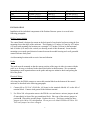
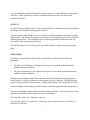
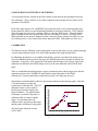
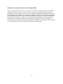
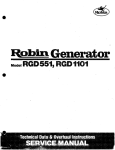
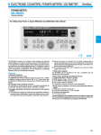
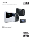
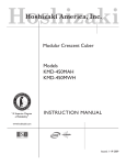
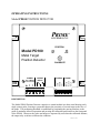
OPERATING INSTRUCTIONS Model PD100 POSITION DETECTOR PRIME CONTROLS, INC. POSITION Model PD100 OK OUT Metal Target Position Detector CALIBRATE SHLD BLACK WHITE PROBE RED CAL RESET CONTROL COM AC AC OUTPUT RELAY METAL POWER SET JUMPERS (120V OR 240V) DESCRIPTION The Model PD100 Position Detector comprises a control module in a sheet metal housing and a single remote probe, forming a system that detects the proximity of a metal target to the face of the probe. The positioning threshold is established by positioning the moving members to the point of maximum allowed separation and pressing the calibration push button on the front panel of the PD100. Whenever the probe and target are separated by more than the calibrated distance, the output relay switches to indicate the condition. January 27, 1999 Control Module The control module allows fast and easy setup and for diagnosis of system errors or problems. Calibration is achieved through the simple press of a push-button switch. Faults are reported through different flash patterns on the green and yellow “OK” and “OUT” indicators. When the unit first powers up, the two indicators flash alternately as the unit determines which model of probe is attached. If the probe is not recognized, the flash pattern changes with the yellow indicator on solid and the green indicator flashing. When probe assessment has completed successfully, the indicators stop flashing NOTE: When power is first applied to the PD100, there must be no metal near the probe face to allow for proper probe identification. Other features of the control module include: • 95 to 130 or 200 to 250 volt operation selected through internal jumpers. • Removable terminal blocks for quick change out of the control module. • Form C relay output providing normally open or normally closed contacts. • LED indicators report the target position states of OK or OUT. • Automatic setup of system gain and operating parameters. • Simple push-button calibration. • Non-volatile memory that retains all calibration parameters even when power is removed. • Latching relay output that is cleared by asserting the RESET input. • Probe fault detection and reporting via the two front panel indicators. • External Calibrate terminals for convenient placement of the calibrate switch • Metal present output to indicates metal sensed even if outside the calibration range. Probes The PD100 operates with a several different Prime magnetic probes including Models PM4, PM10, and PM15. All probes are potted and completely sealed. The probes do not respond to small amounts of fine metal filings, oil or dirt. 2 Probe Model PM4 PM10 PM15 Probe Diameter 18 mm (0.070”) 30 mm (1.18”) 36 mm (1.42”) Min Cal Distance 0 mm (0”) 0 mm (0”) 0 mm (0”) Max Cal Distance 0.6 mm (0.024”) 1.5 mm (0.060”) 2.0 mm (0.080”) INSTALLATION Installation of the individual components of the Position Detector system is covered in the following paragraphs: PD100 Control Module The control board is designed to mount on the back panel of an electrical enclosure using the four mounting slots at the edges of the enclosure. The footprint is 6.5 inches (165 mm) by 6.25 inches (159 mm) with mounting slot locations on a rectangle 5.875 inches (149 mm) in the horizontal and 4.0 inches (102 mm) in the vertical (see drawing at end of this document). Insure that the mounting screws make good electrical contact between the module housing and a well grounded control enclosure back panel. Avoid mounting locations with excessive heat and vibration. Probes The probe must be mounted so that the nearest position of the target is either in contact with the probe or as far away as indicated in the chart found earlier in this document. We recommend maintaining a small separation between the probe and target to minimize shock and prolong the life of the probe. Electrical Wiring All wiring for the PD100 connects to removable terminal blocks at the bottom of the control enclosure as described in the following paragraphs. 1. Connect l00 to l30 VAC (50-6O Hz. @15watts) to the terminals labeled AC on the left of terminal block. Connect earth ground to the leftmost terminal. 2. For 200 to 260 volt operation remove the PD100 cover and remove suitcase jumpers A and C immediately in front of the gray transformer block. Place one of the suitcase jumpers in position B. Discard the second jumper. Replace the cover. The factory setting for these jumpers is for 100 to 130 volt operation. Do not power the Model PD100 with 200 to 260 VAC until jumpers have been changed. 3 3. Connections to the control circuit of the machine are made through the form C output relay. This relay is powered in the OK condition. The relay picture on the front panel of the PD100 indicates the “OK” state. If power is lost to the control the relay is not energized and the relay defaults to the “OUT” state. 4. Shielded cable from the probe to the board should be run in conduit. The probe is connected to terminals on the rightmost terminal block labeled Red, White, Black & Shield. Connect the shield leads (drain wires) from the probe cables to the terminals labeled SHLD. If a splice is made between the control and probe leave the probe unshielded no more than 20 to 30 mm. 5. The output relay may be operated in a "follower" mode or "memory" mode depending upon the wiring of the RESET input. The mode connections and definitions are described below. a) To operate the output in the "follower" mode, jumper RESET and COM. together on the terminal block. When an OUT condition occurs, the relay drops out and the OUT indicator comes on. When the target comes within the OK range again, the relay returns to the normally energized condition, the amber OUT indicator goes out and the green OK indicator turns on. Automatic reset is normally selected to control the operation when the fault condition is automatically removed or the PD100 is wired into the stop circuit of a machine with a manual restart circuit. b) To operate the output in a "latch" mode, wire the RESET and its associated COM terminal to the normally open contact of a switch, relay, or controller output. In this mode, when a fault condition occurs, the relay drops out and the OUT indicator comes on. When the target comes within range again, the RESET contact must be momentarily activated to bring the relay back to the OK state. INPUTS AND CONTROLS The primary control input to the PD100 is the calibration push-button switch on the front panel. Use of this switch is described below under CALIBRATION. The PD100 has two logic inputs labeled CAL and RESET. The CAL input parallels the function of the calibrate push-button on the front panel allowing the calibration function to be performed through a remotely located switch wired to this input. The RESET input controls the latching of the relays as described in item 5 of the Electrical Wiring section above. The two logic inputs have associated with them two jumper plugs located under the front cover and immediately behind its associated terminal. The function of these jumpers is described below under CONFIGURATION SWITCHES AND JUMPERS. Both the CAL and RESET inputs are ON when low (zero volts) independent of the jumper settings. 4 A two position DIP switch between the two main connectors, is visible from the connector edge of the unit. These switches are for future expansion and currently have not effect on the operation of the unit. OUTPUTS The PD100 outputs include a form C relay for reporting OUT conditions and a dc logic output for reporting no metal within sensing range of the probe. The logic output is labeled METAL since it provides an indication that the metal target is within sensing range. The intent of this output is to proximity of the target though it may be outside the calibrated accept zone. This output provides a dc sourcing signal that switches between zero volts and 22 volts, delivering up to 100 mA. The METAL output is ON (sourcing at 22 volts) when material is within sensing range of the probe. INDICATORS The function of the indicators and controls on the PD100 are described in the following paragraphs: 1. The amber OUT indicator is ON whenever the target is beyond the position threshold established during calibration. 2. The green OK indicator is ON whenever the target is at or inside the position threshold as established during calibration. Through various flashing patterns, these indicators also provide information regarding system mode (calibrate vs operate), firmware version number, and error conditions. Reading firmware version is described later in this document. All other flash patterns can be interpreted as follows: Alternate flashing of amber and green indicates busy such as during initialization after power-up. Simultaneous flashing of amber and green indicates failed calibration. This error can occur if the gap between the probe and the target is excessive at calibration. Green flashing, amber off - calibration in process. Green flashing, amber on - probe error. Probe may not be connected, probe wire broken, or probe may be defective. 5 CONFIGURATION SWITCHES AND JUMPERS A two position switch is located on the main control circuit board in the opening between the two connectors. These switches are for future expansion and currently have not effect on the operation of the PD100. Each of the logic inputs (CAL and RESET) has associated with it a two position jumper plug located under the front cover and immediately behind its associated connector. These jumpers allow the inputs to be driven by a sinking (NPN) or sourcing (PNP) device. When the jumper plug is installed on the pins closest to the connector, the input is set up for a sourcing driver. When installed on the two pins farthest from the connector (factory setting), the input is set up for a sinking driver, or dry contact between the input and COM. Both inputs are active low. CALIBRATION The detector may be calibrated via the push-button switch on the front cover or remotely through a switch connected between the CAL and COM terminals of the right terminal block. In calibrating, the objective is to establish a threshold, a position, such that if the probe moves across the threshold and away from the target, the PD100 output relay switches to indicate the separation. Conversely, if the separation of the probe and the target is less than or equal to the separation at calibration, the PD100 output relay is in the state indicated on the PD100 front panel. Thus, to establish the threshold position, simply position the probe and the target at the desired separation and press the CALIBRATE push button on the front panel of the PD100. Alternatively, a remote push button connected across the CAL input may be used. Note that the actual threshold is offset by the amount indicated in the adjacent graph. After the CAL push button is pressed, the system always indicates OK. The OUT Probe Backoff Distances vs Gap at Calibration indication comes on if the probe is backed away from the target by the back-off distance. The smallest backoff distance is realized if the probe is calibrated while in contact with the target. For maximum back-off, calibrate with a gap between the target and the probe as indicated in the graph. 0.021 0.019 Probe Backoff Distance (in.) 0.017 0.015 0.013 0.011 0.009 0.007 PM4 Backoff Distance PM10 Backoff Distance PM15 Backoff Distance 0.005 0.003 The steel target should be at least 0.060” thick. 0.001 0.00 0.01 0.02 0.03 0.04 0.05 0.06 Gap at Calibration (in.) 6 0.07 0.08 0.09 FIRMWARE VERSION From time to time, as improvements are made to Prime products, the firmware controlling the units is revised. When setting a unit up or troubleshooting it may be necessary to determine the version number for the firmware installed in your unit. The version numbers begin with 1.0 and are incremented either by tenths (1.1, 1.2, etc.) for small revisions or by the integer digit (1.0, 2.0, etc.) for more significant revisions. To determine the version of the firmware running in your unit, simply hold the calibration push button in as power is applied to the unit. The revision number is displayed as one second flashes of the green LED for the integer digit followed by one second flashes of the amber LED for the fractional digit. Count the number of flashes on each LED to determine the revision number. Thus one flash of the green followed by two flashes of the amber LED indicates version 1.2 of the firmware. POWER REQUIREMENTS 95 to 130 volts, 50/60 Hz at 50 mA. OUTPUT RELAY SPECIFICATIONS Maximum switched voltage: Maximum switched current: Maximum switched power: Minimum required contact load: 380VAC 14 amps N.O., 5 amps N.C, AC resistive, 8 amps DC 20OW DC, 2,OOOVA AC. 12V, 100 mA Expected mechanical life: 20 million operations Expected electrical life: 100,000 operations at 8 amps, 240VAC 50,000 operations at 14 amps N.O., 5 amps N.C., 120VAC resistive 30,000 operations at 7.2FLA, 45LRA, 120VAC 10,000 operations at 5FLA, 30 LRA, 240VAC 7 TROUBLESHOOTING Should trouble develop, proceed as follows: 1. Check AC input power to the control module 2. Check the fuse, accessible at the lower left side of the PD100 housing. 3. When powers is applied, if the green and amber indicators show a response to the metal condition in front of the probe and the output relay does not switch, check that the reset jumper is installed (if you want the relay to follow the metal condition). The jumper is installed between RESET and COM. on the terminal strip. If the unit is reset by an external machine START button, check wiring across the Reset and COM terminals or the START button contacts. 4. When power is applied, if the OUT indicator is on solidly while the OK indicator is flashing, check for a missing, disconnected, open, or shorted probe. 5. If both indicators flash in unison, the system is indicating an invalid calibration. The causes can be many. Among them, an attempt to calibrate with the target too far from the probe, a shorted receiver probe, incorrect probes for the material being gauged. If the problem cannot be resolved, call the factory for assistance. For further information or service assistance, contact Prime Controls, Inc., 4551 Gateway Circle, Dayton, Ohio 45440-1711. Phone: (937) 435-8659, Fax: (937) 435-2091. Mention model number and serial number. 8 165.1 (6.50) 149.2 (5.875) 7.9 (0.31) PRIME CONTROLS, INC. POSITION Model PD100 OK OUT 101.6 (4.0) 158.8 (6.25) Metal Target Position Detector CALIBRATE 28.6 (1.125) SHLD BLACK WHITE CAL PROBE RED COM RESET CONTROL AC AC OUTPUT RELAY METAL POWER SET JUMPERS (120V OR 240V) 15.2 (0.600) 9 33.5 (1.32) LIMITATION AND EXCLUSION OF WARRANTIES All goods purchased from Prime Controls, Inc. shall be free from defects in materials, design and workmanship under normal conditions of use for one year from the date of shipment. THIS WARRANTY IS THE SOLE WARRANTY AND IS EXPRESSLY IN LIEU OF ALL OTHER WARRANTIES, EXPRESSED OR IMPLIED, INCLUDING BUT NOT LIMITED TO ANY IMPLIED WARRANTY OF MERCHANTABILITY OF FITNESS FOR A PARTICULAR PURPOSE. THE LIABILITY OF PRIME CONTROLS TO ANY PURCHASER SHALL BE LIMITED EXCLUSIVELY TO THE COST OF REPLACEMENT OR REPAIR OF DEFECTIVE PARTS, AND SHALL NOT INCLUDE LIABILITY FOR ANY DIRECT, CONSEQUENTIAL OR INCIDENTAL DAMAGES WHATSOEVER, WHETHER FORESEEN OR UNFORESEEN, INCLUDING BUT NOT LIMITED TO LOST PROFITS, LOST SALES, OR INJURY TO PERSONS OR PROPERTY. 10