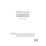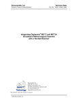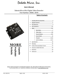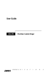
1
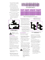
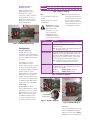
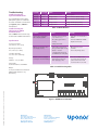
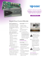
radiant h eating S ystems
u p onor C l im a t e C o˘ ntro l ™
n e twor k s y st e m digit a l
zon e contro l modu l e
INSTRUCTION Sheet
Digital Zone Control Module
The Uponor Climate C˘ontrol™
Network System Digital Zone Control
Module (DZCM) (A9011500) provides
a connection hub for the thermostats
and thermal actuators in the Network
System. Any installation can support up
to 12 DZCMs.
Each DZCM provides connections
for 10 thermostats and 10 thermal
actuators. The Climate C˘ontrol
Network System is designed to
operate specifically with the following
thermostats:
• Climate C˘ontrol Surface Mount
Thermostat, vertical display
(A9010510)
You will need the following tools to
install the DZCM:
• Small-blade screwdriver
• Standard-size screwdriver
• Three mounting screws no larger
than #8
• RJ45 crimper and connectors
• Wire stripper and cutter
Note: Use the Climate C˘ontrol
Thermal Valve Actuator with
Molex Plug (A9010501) when
connecting manifold actuators
or Uponor thermal zone valves.
These actuators come with a
modular plug for simple plug-in
connections to the DZCM.
• Climate C˘ontrol Flush Mount
Thermostat, horizontal display
(A9010530)
Installation
• Climate C˘ontrol Flush Mount
Thermostat, vertical display
(A9010520)
Follow the instructions below to
mount the DZCM.
• Climate C˘ontrol Wall Sensor, no
display (A9010540)
Note: Other thermostats will not
function properly in the Climate
C˘ontrol Network System.
Getting Started
Check the contents of this package. If
any contents listed below are missing
or damaged, contact your Uponor
sales representative or distributor for
assistance. Contents include:
• Digital Zone Control Module
Mounting the DZCM
1. Mount the DZCM within 3 feet
(1 meter) of the actuators. If this
is not possible, you will need to
extend the actuator wires.
2. Gently pull the left cover legs from
the white base, and slide the cover
to the right.
3. Place three #8 (or smaller) screws
in the mounting holes and attach
to a solid surface.
4. After properly installing the unit,
replace the cover by pushing it
straight onto the base.
Figure 1: Mounting the Unit
Caution: Before wiring,
disconnect electrical power
to the system to prevent
electrical shock and
damage to the device.
Note: All wiring must comply with
local electrical codes. For all
terminal block connections to
the thermostats and power
source, use 18 AWG LVT or
similar wire. To ensure proper
connection to the terminal
blocks, strip all wires to 1/4"
(6.3 mm)
Caution: Connect 24VAC
to the power input terminals
only. Do not connect 24VAC
to any other terminals on
this control.
Thermostat Wiring
Refer to the following guidelines
before wiring a thermostat.
1. Use only thermostats specifically
designed for the Uponor Climate
C˘ontrol Network System.
2. U
se 18-2 LVT thermostat wire.
3. Since the thermostats operate
on DC voltage requiring correct
polarity, ensure the plus (+) on the
thermostat is connected to the plus
(+) on the DZCM and the minus (–)
is connected to the minus (–).
Note: Reversed polarity will not damage
the thermostat or DZCM.
4. Due to the low power requirements
of the thermostat, you may make
connections to the thermostat
while power is applied to the
DZCM.
Figure 2: Typical
Thermostat Connection
Caution: Do not apply
24VAC to any thermostat
ports.
Actuator Wiring
Use only Uponor Climate C˘ontrol
Network System Actuators with
the DZCM. These actuators feature
connectors for fast installation —
simply plug in the actuators to the
appropriate ports. You can also extend
the DZCM-to-actuator cable up to
100 feet (35 meters). Simply splice
the wires by color.
The thermostats are mapped to control
specific manifold valve actuators based
on how they connect to the DZCM.
Mapping is governed by the following
three rules.
1. A thermostat will control an
actuator connected to the port
directly below it.
2. When no thermostat is located
directly above an actuator, the
actuator is mapped to the next
thermostat to the left of the actuator.
Port Number
1
Thermostats
X
Valve Actuators X
2
3
X
X
8
9
10
X
4
5
X
X
X
X
X
X
X
6
7
X
Table 1: Mapping equipment
(The circled equipment is mapped together.)
Number of
Actuators
1
2
3
4
VA Required
Number of Actuators
VA Required
6.0*
9.6
14.4
19.2
6
7
8
9
28.8
33.6
38.4
43.2
5
24.0
10
48.0
*Minimum requirement to power the board and 10 thermostats
Table 2: Power Requirements for Actuators
3. A thermostat does not have to
control an actuator to start a heat
demand. The plug opposite the
thermostat can be left open. When
a thermostat does not control an
actuator, connect that thermostat
to the highest-number thermostat
port (i.e., 10, then 9, then 8, etc.).
Note:All screw terminals used for
connecting power and devices
are blocks and can be removed
from the board. This feature
allows you to disconnect wiring
temporarily without the need
for remaking the connections.
Connecting Power
Follow the instructions below to
connect power to the DZCM.
1. Run a single pair of 18 AWG LVT
wire from a 24VAC source to the
DZCM power terminal block.
2. If using a single power transformer
for multiple DZCMs, ensure the
polarity to the power inputs is
identical.
3. Since there is a limit of 10 outputs for
actuator connections, the maximum
transformer requirement is 50VA.
The transformer requirements for the
number of actuators you are using
(one though ten) are listed in Table 2.
Important: In installations
where more than one DZCM
board is powered by the
same transformer, make sure
polarity is followed (R to
R, C to C). If polarity is not
followed, communication
will be interrupted and
equipment will not operate
properly.
Figure 3 shows wires being
crossed in the “wrong way”.
Network and Main Panel Wiring
Correct
Incorrect
Figure 3: Correct vs. Incorrect
Polarity Wiring
A Cat5e cable connects the Router
Main Control’s ports, named Digital
Zone Control Modules, to the network
connector (RJ45) on the right side of
the DZCM board.
Begin plugging DZCM's into the
roughter, using the top available port.
Failure to do so will cause DZCM's to
not communicate on the network.
This cable may also connect to a
Y-Connector when other DZCMs are
installed in the network system.
Note: Total length of Cat5 cable in
any daisy-chain configuration
should not exceed 500 feet.
Refer to Appendix A in the
Uponor Climate C˘ontrol
Network System Manual for
more information about wiring
field-device networks.
Wiring Retrofits for
Existing Systems
A Network Wire Converter
(A9011002) adapts existing
thermostat wire to CAT5e
connections, making it a network.
See Appendix A in the Uponor
Climate Co˘ntrol Network System
Manual for more information on
wiring a DZCM network.
Address
Setting
1
1
2
2
3
3
4
4
5
5
Note:
• Do not use address settings 0, D,
E and F.
• Address settings do not have to
be sequential.
9
9
10
A
11
B
12
C
Note: All screw terminals used for
connecting power and devices
are blocks and can be removed
from the board. This feature
allows you to disconnect wiring
temporarily without the need
for remaking the connections.
Definition
Lights when 24VAC is applied to the control
TX and RX
Flash rapidly when the control transmits or
receives information.
Note: The green TX light is often dimmer than the red
RX light. This is normal.
Thermostat LED
Thermostat indicators are located at the top row of the
DZCM. These yellow lights indicate when a thermostat
communicates with the DZCM. Communication to the
thermostats does not happen regularly so these lights
are often unpredictable during normal operation.
Note: A solid yellow indicator will not show a heat
demand corresponding to the thermostat.
Actuator
Actuator indicators are located on the bottom row of
the DZCM. These red lights display the current action
of their respective actuator.
On = Open
Flashing quickly = Opening
Off = Closed
Flashing slowly = Closing
Actuator Mapping
The mapping process takes
approximately 60 seconds to
complete. When mapping is complete,
the thermostat and actuator lights
will display the mapped configuration
and will continue to cycle for
approximately two to three minutes.
If the map is not correct, swap the
actuators and thermostat plugs that
are connected incorrectly and re-map
the DZCM, using the Map button or
resetting the power to the DZCM.
8
8
Indicator
On
Configuration
Actuator mapping occurs
automatically each time the DZCM
powers up or when a user presses and
holds the red Map button for at least
15 seconds.
7
7
Table 3: Address Settings
Important: After making
any changes to the DZCM
(address, thermostat
connections, etc.), cycle
power to the unit by
unplugging the power
terminal strip for at least 10
seconds before reconnecting.
Figure 4: DZCM Network Wiring
6
6
Table 4: Indicator Definitions
Addressing
Each DZCM in a system will
require a different address to avoid
communication issues. Use a smallblade screwdriver to set the rotary
address switch on the left side of
the DZCM. The address dial has
16 possible settings, but only 12
are available, as shown in Table 3.
Map Button
Address Switch
Figure 5: Actuator Mapping
Figure 6: DZCM Indicators
Indicators
There are several indicators on the left
side of the DZCM which display the
status of the control. Refer to Table 4
for definitions of the various indicators.
Troubleshooting
Troubleshooting the
System Communications
The TX and RX light-emitting diodes
(LEDs) work together to communicate
the status of the CAT5e communications
(see Figure 6). Refer to Table 4 for
LED definitions.
Troubleshooting the
Thermostat to DZCM
Communications
Refer to Table 5 when troubleshooting
the thermostat-to-DZCM communications.
Red LED
Green LED
Status
Flashing
Flashing
Normal Communication
None required
Flashing
Not Lit
Wiring problem
Test or rewire the CAT5e cabling
Not Lit
Flashing
Wiring problem
Test or rewire the CAT5e cabling
Solid
Not Lit
Wiring problem
Change 24VAC input polarity
Not Lit
Solid
Wiring problem
Change 24VAC input polarity
Table 4: LED Definitions
Problem
Cause
Remedy
Thermostat is plugged in,
but no display appears
•P
olarity issue (not wired
+ to + and – to –)
• No power (green LED is
not lit)
• Faulty thermostat
• Swap wires on thermostat or
DZCM.
•C
onnect DZCM with 24VAC.
• Replace thermostat.
Outdoor temperature does
not display properly
• Thermostat is wired on the
wrong terminals (slab sensor).
•C
heck or test the
communication wire from
the DZCM to the main panel.
• Move wires to proper
terminals.
• Correct any wiring issues.
Actuators are not mapped
correctly to the thermostat(s)
• A change was made to the
thermostat connections
after applying power.
• Press the red Map button
to re-map, then remove the
power terminal block and
reconnect after 10 seconds.
Specifications
Storage Temperature:
14 to 160°F (-10 to 70°C)
Operating Temperature:
32 to 105°F (0 to 40°C)
% Relative Humidity:
10 to 90% non-condensing
Voltage:
24VAC +/- 10%, 50-60Hz
Power Draw:
50 VA maximum for each DZCM
Output:
For Uponor Climate C˘ontrol Network
Manifold Valve Actuators only
(A9010501)
CCN-DZCM_H064_IS_5-08, Copyright © 2008 Uponor, Inc., Printed in the United States
Remedy
Table 5: Troubleshooting Table
Figure 7: DZCM Board Schematic
Uponor, Inc.
5925 148th Street West
Apple Valley, MN 55124 USA
Phone: (800) 321-4739
Fax: (952) 891-2008
www.uponor-usa.com
Uponor Ltd.
655 Park Street
Regina, SK S4N 5N1 CANADA Phone: (888) 994-7726
Fax: (800) 638-9517
www.uponor.ca