1
USER INSTRUCTIONS
IDMxxx corded
Hand-held Scanners
General Remarks
User Instructions
IDM corded
General Remarks
Further information on the IDM corded Hand-held scanners can be found on the internet on the IDM product
page at www.mysick.com
• Detailed technical data in the online data sheet
• Overview of accessories
• Configuration software IDM Set Up Tool
• EC Declaration of Conformity
• Identification solutions product catalog
• Product information Hand-held scanners
Deutsche Version/ German version
Diese Betriebsanleitung ist auch in Deutscher Sprache verfügbar und kann auf www.mysick.com
heruntergeladen werden.
Print out this manual
If you want to print out this manual please ensure that the original size is remained and the print out is of
good quality. Otherwise the configuration codes contained in this manual may be distorted and cannot be
scanned anymore.
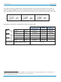
Regulatory
KN22, KN24 (KN61000-2,-3,-4,-5,-6,-8,-11)
Part 15 Subpart B
EN61000-3-2/ EN61000-3-3 1,
V-3/2011.04, TECHNICAL REQUIREMENTS,
EN60950-1, EN61000-6-3,
Class B ITE
EN61000-6-2 2
CNS13438
LED Eye Safety
IEC62471 Exempt group
AS/NZS CISPR 22:2009 Class B
Laser Eye Safety
IEC60825-1 Class 1
Copyright
Copyright © 2013
SICK AG Waldkirch
Identification & Measuring, Reute Plant
Nimburger Strasse 11
79276 Reute
Germany
Trademark
Adobe™ Reader™ is a trademark of Adobe Systems Incorporated.
1
2
2
Relevant for delivery with power supply.
At the presence of high frequency interference in the frequency range of 15 MHz to 50 MHz there may be performance restrictions.
© SICK AG · Germany · All rights reserved · Subject to change without notice
8015906/2013-07-02
User Instructions
Table of contents
IDM corded
Table of contents
1 2 Getting Started..................................................................................................................................................... 5 1.1 Getting familiar with your IDM Hand-held scanner......................................................................... 5 1.2 Connectivity ....................................................................................................................................... 5 1.3 Technical Specifications................................................................................................................... 7 Configuration........................................................................................................................................................ 8 2.1 Programming Commands................................................................................................................. 8 2.1.1 System Command................................................................................................................ 8 2.1.2 Family Code .......................................................................................................................... 8 2.1.3 Option Code.......................................................................................................................... 8 2.2 Programming Procedures................................................................................................................. 8 2.2.1 Program & End ..................................................................................................................... 9 2.2.2 System List & Master Default ........................................................................................... 10 2.2.3 Single Scan Selection ........................................................................................................ 10 2.2.4 Multiple Scan Selection..................................................................................................... 11 2.2.5 Cycling Scan Selection....................................................................................................... 12 2.2.6 Dual Level Scan Selection................................................................................................. 13 2.3 Host Interface Selection ................................................................................................................. 14 2.4 Symbology Reading Control............................................................................................................ 15 2.4.1 User Defined Symbol ID..................................................................................................... 15 2.4.2 Symbology ID Transmission .............................................................................................. 16 2.4.3 Readable Bar Code Setting ............................................................................................... 17 2.4.4 Code 39/ Code 32 Settings .............................................................................................. 19 2.4.5 Code 39 Settings ............................................................................................................... 20 2.4.6 Codabar/ NW-7 Settings.................................................................................................... 21 2.4.7 UPC-A/ UPC-E Settings....................................................................................................... 22 2.4.8 EAN Settings....................................................................................................................... 25 2.4.9 UCC Coupon Extended Code Settings .............................................................................. 27 2.4.10 IATA & Interleaved 2 of 5 Settings.................................................................................. 28 2.4.11 Code 25 Family Settings ................................................................................................. 29 2.4.12 Code 11 & Code 93 Settings .......................................................................................... 30 2.4.13 MSI/ Plessey Settings ..................................................................................................... 31 2.4.14 Code 128 Settings........................................................................................................... 32 2.4.15 GS1-128 Settings ............................................................................................................ 33 2.4.16 UK/ Plessey Settings ....................................................................................................... 34 2.4.17 Telepen Settings .............................................................................................................. 35 2.4.18 GS1 DataBar Settings ..................................................................................................... 36 2.4.19 Composite Codes, Codablock F, PDF417, Micro PDF417 Settings ............................. 37 2.4.20 Code 16K & Code 49 Settings........................................................................................ 38 2.4.21 QR Code Settings............................................................................................................. 39 2.4.22 Data Matrix Settings........................................................................................................ 40 2.4.23 Aztec Code Settings......................................................................................................... 41 2.4.24 Autralian Post, US Planet, US Postnet, British Post, Japan Post Settings ................... 42 2.4.25 Netherland KIX Code, Intelligent Mail & Korea Post Code Settings ............................. 43 2.5 Keyboard Interface Control ............................................................................................................ 44 2.5.1 Keyboard Layout (Language) Settings.............................................................................. 44 2.5.2 Record Suffix, Preamble, Postamble, FNC1 Transmit, Caps Lock.................................. 45 8015906/2013-07-02
© SICK AG · Germany · All rights reserved · Subject to change without notice
3
Table of contents
User Instructions
IDM corded
3 4
2.5.3 Delay Settings .................................................................................................................... 46 2.5.4 Emulation Settings, Key Pad Emulation, Upper/Lower Case Settings ........................... 47 2.6 Serial Interface Control................................................................................................................... 48 2.6.1 Record Suffix, Preamble, Postamble Settings ................................................................. 48 2.6.2 Delay Settings .................................................................................................................... 49 2.6.3 Protocol, ACK/ NAK Settings............................................................................................. 50 2.6.4 Response Time-out, Baud Rate Settings.......................................................................... 51 2.6.5 Data Frame Settings .......................................................................................................... 52 2.7 Wand/ Laser Emulation Control (IDM1xx series).......................................................................... 53 2.7.1 Output Polarity, Signal State, Margin/ Module Time ....................................................... 53 2.8 Operation Control (IDM1xx series)................................................................................................. 54 2.8.1 Operation Mode Setting..................................................................................................... 54 2.8.2 Presentation Control, Scan Rate, Flash Duty ................................................................... 56 2.8.3 1D Barcode Reading Direction.......................................................................................... 57 2.9 Operation Control (IDM2xx series)................................................................................................. 58 2.9.1 Operation, Presentation and Illumination Control ........................................................... 58 2.9.2 Aiming Control, Delay Aiming, Decode Aiming Control .................................................... 59 2.9.3 Center Alignment, Unique Barcode Reporting ................................................................. 60 2.9.4 Batch Reading.................................................................................................................... 61 2.10 Operation Control (all IDM series).................................................................................................. 64 2.10.1 Buzzer, Indicator, Vibrator Control.................................................................................. 64 2.10.2 Dollar Sign, Redundancy, 1D Code Inverse Reading .................................................... 65 2.10.3 Reread Delay, Good Read Delay Control........................................................................ 66 2.10.4 Light Source On Time, Hands Free Time-out ................................................................. 67 2.10.5 Presentation Auto-Sense , Sensitivity............................................................................. 68 2.11 Condensed Data Wizard ................................................................................................................. 69 2.11.1 Preamble, Postamble, Data Length, Symbol ID Transmission ..................................... 69 2.11.2 Data Formatter Settings.................................................................................................. 70 2.11.3 Data Verifier Settings ...................................................................................................... 71 2.11.4 Data Replacer Settings ................................................................................................... 72 2.11.5 Data Organizer Settings .................................................................................................. 73 2.11.6 Select a Barcode Symbology........................................................................................... 74 2.11.7 Position Calculation......................................................................................................... 75 2.11.8 Application Example ........................................................................................................ 75 Appendix ............................................................................................................................................................. 77 3.1 Symbology ID Table (1D Codes) ..................................................................................................... 77 3.2 Symbology ID table (2D and Post codes) ...................................................................................... 78 3.3 Keyboard Function Code Table ...................................................................................................... 78 3.4 ASCII Input Shortcut (Reference Table) ......................................................................................... 79 3.5 Host Interface Quick Set................................................................................................................. 80 3.6 Operation Mode Quick Set (IDM1xx series) .................................................................................. 81 3.7 Operation Mode Quick Set (IDM2xx series) .................................................................................. 82 3.8 Option Codes................................................................................................................................... 83 3.9 System Commands ......................................................................................................................... 84 © SICK AG · Germany · All rights reserved · Subject to change without notice
8015906/2013-07-02
Getting familiar with your IDM Hand-held scanner
User Instructions
IDM corded
1
Getting Started
1.1
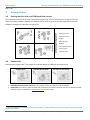
Getting familiar with your IDM Hand-held scanner
The IDM family includes 1D scanners with linear imagers and 2D scanners with area imagers. There are
different models available. IDMx20 and IDMx40 can be used for general purpose applications whereas
IDMx60 is designed for industrial environments.
IDM120 Series
IDM140 Series
IDM160/260 Series
IDM240 Series
Power Indicator
Status Indicator
Trigger
Scan Window
Beeper
Cable Release Hole
Tether Plate
Lanyard Catch
1.2
Connectivity
1
IDM scanners support USB , PS/2(DOS/V) Keyboard Wedge and RS-232 Serial interfaces.
USB HID & USB COM
RS-232 Serial
PS/2 Keyboard Wedge
USB HID (Human Interface Device): The scanner works as a generic USB Keyboard.
USB COM: The scanner works as a RS-232 serial device. Please note that you have to install the USB
COM Port driver (available on www.mysick.com) before using.
1
USB is not suitable for use in industrial environments. Therefore, at cable installation it is important to ensure that there are no close
sources of interference.
8015906/2013-07-02
© SICK AG · Germany · All rights reserved · Subject to change without notice
5
Connectivity
User Instructions
IDM corded
To connect the scanner, plug the cable into the interface port of the scanner and connect it to the host. To
remove the cable, straighten one end of a paper clip and insert it into the cable release hole to pull out the
cable. For IDM160/260 series you need to push down the bracket of the enclosure clip and pull out the cable.
IDM120 Series
IDM140/240 Series
IDM160/260 Series
Depending on the Scanner model different cables have to be used.
USB
RS-232
PS/2
Power Supply
IDMx20, IDMx40,
IDMxxx Bluetooth
IDMx60
IDMx40 Wifi
IDMx60 Wifi
straight
1.8 m
6036728
6045195
6036728
spiral
3.8 m 1
6039158
6045232
6039158
straight
1.8 m
6041540
6045196
-
spiral
3.8 m
6039156
6045233
-
straight
2.0 m
6036726
6045194
-
spiral
3.8 m
6039155
6045231
-
needed for operation with RS-232
cables 2, Bluetooth and Wifi
6036722
1
If you want to use this cable for USB Com Port Mode, it is recommended to use an additional USB hub between cable and PC. The
USB hub will boost the communication signal and secure the communication.
2
If there is no power on Pin 6 or 9.
6
© SICK AG · Germany · All rights reserved · Subject to change without notice
8015906/2013-07-02
Technical Specifications
User Instructions
IDM corded
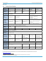
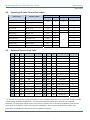
1.3
Technical Specifications
Type
IDM120
IDM140
IDM160
IDM240
IDM260
Field of
application
General Purpose
General Purpose
Industrial
General
Purpose
Industrial
Enclosure
rating
IP 41
IP 41
IP 65
IP 41
IP 65
Supported
code types
1D, Stacked 1
1D, Stacked, 2D
≥0.102 mm1)
≥0.076 mm1)
SR model:
≥0.08 mm1), ≥0.18 mm2)
HD model:
≥0.08 mm1), ≥0.13 mm2)
50 mm ... 600 mm
(0.5 mm)1)
SR model:
30 mm ... 155 mm (0.25 mm)2)
HD model:
35 mm ... 90 mm (0.13 mm)2)
Code
resolution
1)
Reading
distance
(at code
resolution)
0 mm ... 250 mm
(0.33 mm)1)
Interfaces
USB (Keyboard Wedge & Com Port Emulation), RS-232 TTL, PS/2
(Ethernet TCP/IP, PROFINET, PRODIBUS, DeviceNet) 2
Optical
indicators
1 LED
(good read)
2 LEDs (operational status, good read)
Vibration
No
No
Acoustic
indicators
Beeper, disengageable
Operating
Voltage
5 V DC (+/- 5%)
50 mm ... 800 mm
(0.5 mm)1)
Yes
Current
consumption
(Operating)
Typical
170 mA
Typical 180 mA
180 mA
(Vibrator disabled)
230 mA
(Vibrator enable)
Current
consumption
(Standby)
Typical 75 mA
Typical 80 mA
Typical 90 mA
Light source
LED: visible red light (630 nm)
Laser aimer
No
Ambient
operating
temperature
0 °C ... 50 °C
Storage
temperature
-20 °C ... 60 °C
No
Yes
Typical 285 mA
Max. 285 mA
(Vibrator disabled)
Max. 335 mA
(Vibrator enable)
Typical 160 mA
Max. 150 mA
Yes
-40 °C ... 70 °C
-20 °C ... 50 °C
-10 °C ... 50 °C
-20 °C ... 50 °C
-30 °C ... 70 °C
-40 °C ... 70 °C
-40 °C ... 70 °C
Valid for Code 39, 2) Valid for Data Matrix
For detailed technical specifications, see the Online Data Sheet on the product site on the web
(www.mysick.com/en).
1
2
Depending on scanner version (To be able to read stacked codes, PDF version is necessary).
Optional via external SICK connection modules.
8015906/2013-07-02
© SICK AG · Germany · All rights reserved · Subject to change without notice
7
Programming Commands
User Instructions
IDM corded
2
Configuration
2.1
Programming Commands
The IDM scanner bar code commands are specially designed proprietary bar code labels which allow you to
set the IDM Scanner’s internal programming parameters. There are System Command, Family Code and
Option Code for programming purpose.
Each programmable family and bar code command label is listed on the same page with major system
commands. The detailed explanations and special programming flowchart are printed on facing or following
pages. The Option Codes and System Commands can be found in the appendix on page 83 and 84.
2.1.1 System Command
The System Command is the highest level bar code command which directs the IDM Scanner to perform
immediate operations, such as entering programming mode (PROGRAM), exiting programming mode (EXIT),
listing system information (SYSLIST), recovering to factory preset configurations (M_DEFAULT) and so on.
Please note that all system commands will take a few seconds to complete the operations. User must wait for
the completion beeps before scanning another bar code.
2.1.2 Family Code
The Family Code is scanned to select the user desired programming family. IDM Scanner has already provided
more than one hundred programming families to meet any specific requirements.
2.1.3 Option Code
The Option Codes is a set of bar code commands represented by “0–9”, “A–F” and finishing selection (FIN).
For most setting, you must select at least one option code following the family code selection to set the
desired parameter for the selected programming family. The Option Codes can be found on page 83.
2.2
Programming Procedures
As you scan the bar code command to select the desired parameters, information about the final selected
parameters represented by the bar code commands are stored in the Hand-held scanner’s internal Flash
Memory ASIC or non-volatile memory. If you turn off the unit, the Flash Memory ASIC or non-volatile memory
retains all programming options. You don’t need to re-program the IDM Scanner if you want to keep the
existing configurations in the next power on.
The programming procedures of the IDM Scanner are designed as simple as possible for ease of setting. Most
programming families take the “Single Scan Selection” programming procedure. But several programming
families have more complex and flexible programmable options, and you must take “Multiple Scan Selection”,
“Cycling Scan Selection” or “Dual Level Selection” to complete their programming procedures. Each kind of
programming procedure is listed in the following pages for your reference. Please give careful attention to
become familiar with each programming procedure.
8
© SICK AG · Germany · All rights reserved · Subject to change without notice
8015906/2013-07-02
Programming Procedures
User Instructions
IDM corded
If the programming family must take “Multiple Scan Selection”, “Cycling Scan Selection”, or “Dual Level
Selection” procedures, the family of the programming menu will be marked with the matched representing
symbol of Programming Category (P.C.) listed in the following table.
Conventions
Descriptions
Factory default value
Programming category
SS: Single scan selection
P.C.
MS: Multiple scan selection
CS: Cycling scan selection
DS: Dual level scan selection
( )
Necessary option code
[ ]
Selectable option code
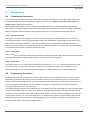
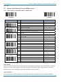
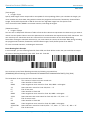
2.2.1 Program & End
Scan
„PROGRAM“
Scan
„END“
The scanner will enter programming
mode and inhibit all nonprogramming functions.
The scanner will exit programming
mode, and store all parameters in
Flash Memory ASIC or non-volatile
memory, then issue the completion
beeping.
Please note that the IDM Scanner will take 3-4 seconds to store parameters in internal Flash Memory
ASIC or non-volatile memory after you scan the “END”. Please don’t turn off the power before the
completion beeping. It may destroy all configured parameters.
8015906/2013-07-02
© SICK AG · Germany · All rights reserved · Subject to change without notice
9
Programming Procedures
User Instructions
IDM corded
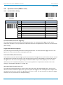
2.2.2 System List & Master Default
Scan
„M_DEFAULT”
Scan
„SYSLIST“
The scanner will list the product
information and revision number to
host via selected host interface,
then issue the completion beeping.
The scanner will list the product
information and revision number to
host via selected host interface,
then issue the completion beeping.
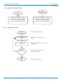
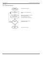
2.2.3 Single Scan Selection
Scan
„PROGRAM“
Yes
Enter Programming mode.
Scan one of family
codes
Select the desired programming
family.
Scan one of option
codes
Select one option code for the desired
parameter.
Repeat
selection
Do you want to select another
programming family?
No
Scan
„END“
10
Exit programming mode.
© SICK AG · Germany · All rights reserved · Subject to change without notice
8015906/2013-07-02
Programming Procedures
User Instructions
IDM corded
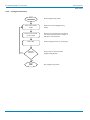
2.2.4 Multiple Scan Selection
Scan
„PROGRAM“
Yes
Enter Programming mode.
Scan one of family
codes
Select the desired programming
family.
Scan one or several
option codes
Select one or several option codes for
the desired parameters.
If it‘s necessary scan „FIN“ to
terminate the option code selection.
Repeat
selection
Do you want to select another
programming family?
No
Scan
„END“
8015906/2013-07-02
Exit programming mode.
© SICK AG · Germany · All rights reserved · Subject to change without notice
11
Programming Procedures
User Instructions
IDM corded
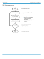
2.2.5 Cycling Scan Selection
Scan
„PROGRAM“
Yes
Enter Programming mode.
Scan one of family
codes
Select the desired programming
family.
Scan one or several
option codes
Select one or several option codes for
the desired parameters as “Single” or
“Multiple” scan selection.
Scan “FIN”
Finish cycling selection. (If necessary)
Repeat
selection
Do you want to select another
programming family?
No
Scan
„END“
12
Exit programming mode.
© SICK AG · Germany · All rights reserved · Subject to change without notice
8015906/2013-07-02
Programming Procedures
User Instructions
IDM corded
2.2.6 Dual Level Scan Selection
Scan
„PROGRAM“
Scan one of family
codes
st
(1 ) Scan several
option codes
nd
(2 ) Scan one or
several option codes
Yes
Repeat
selection
Enter Programming mode.
Select the desired programming
family.
Select several option codes for the
desired parameters.
1. Select one or several option
codes for the desired
parameters.
2. If it’s necessary scan “FIN” to
terminate the option code
selection.
Do you want to select another
programming family?
No
Scan
„END“
8015906/2013-07-02
Exit programming mode.
© SICK AG · Germany · All rights reserved · Subject to change without notice
13
Host Interface Selection
User Instructions
IDM corded
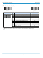
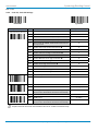
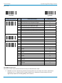
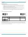
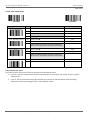
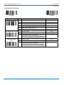
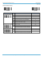
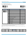
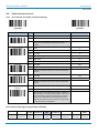
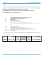
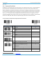
2.3
Host Interface Selection
PROGRAM
F_DEFAULT
Family Code Selection
P.C.
Parameter Selection
Option Code
Host Interface Selection
MS
IBM PS/2 25-30 series keyboard wedge interface
02
MS
Standard/TTL RS-232 peer-to-peer serial
06
MS
Wand Emulation
08
MS
USB Com Port Emulation
09
MS
PS/2 (DOS/V) direct link (keyboard replacement)
10
MS
PS/2 (DOS/V) keyboard wedge turbo mode
13
MS
PS/2 (DOS/V) keyboard wedge standard mode
14
MS
Laser emulation
17
MS
USB HID standard mode
18
MS
USB HID turbo mode
19
MS
USB HID Legacy
20
IDM2xx series doesn’t support Wand emulation, Laser emulation and USB HID Legacy
14
© SICK AG · Germany · All rights reserved · Subject to change without notice
8015906/2013-07-02
Symbology Reading Control
User Instructions
IDM corded
2.4
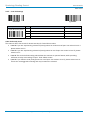
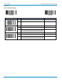
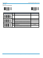
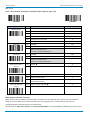
Symbology Reading Control
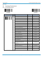
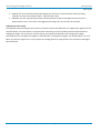
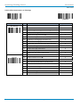
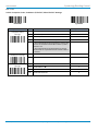
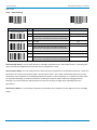
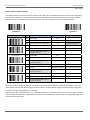
2.4.1 User Defined Symbol ID
PROGRAM
F_DEFAULT
Family Code Selection
P.C.
Symbol ID 1 character
DS
8015906/2013-07-02
Parameter Selection
Option Code
2nd Option Code
Code 128 (default=B)
00
(1 character)
GS1-128 (default=C)
01
(1 character)
UPC-A (default=A)
02
(1 character)
EAN-13 (default=F)
03
(1 character)
Codabar/NW-7 (default=D)
04
(1 character)
Code 39/Code 32 (default=G)
05
(1 character)
Code 93 (default=H)
06
(1 character)
Standard/Industrial 2 of 5 (default=I)
07
(1 character)
Interleaved 2 of 5 (default=J)
08
(1 character)
Matrix 2 of 5 (default=K)
09
(1 character)
China Postal Code (default=L)
10
(1 character)
German Postal Code (default=M)
11
(1 character)
IATA (default=O)
12
(1 character)
Code 11 (default=P)
13
(1 character)
MSI/Plessey (default=R)
14
(1 character)
UK/Plessey (default=S)
15
(1 character)
Telepen (default=T)
16
(1 character)
GS1 DataBar (default=X)
17
(1 character)
UPC-E (default=E)
18
(1 character)
EAN-8 (default=N)
19
(1 character)
Trioptic Code 39 (default=W)
20
(1 character)
UCC Coupon Extended Code
(default=Z)
21
(1 character)
PDF417/Micro PDF417 (default=V)
22
(1 character)
Codablock F (default=Y)
23
(1 character)
Code 16K (default=Q)
24
(1 character)
Code 49 (default=U)
25
(1 character)
Korea Post Code (default=a)
26
(1 character)
© SICK AG · Germany · All rights reserved · Subject to change without notice
15
Symbology Reading Control
User Instructions
IDM corded
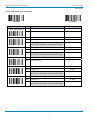
PROGRAM
F_DEFAULT
Family Code Selection
P.C.
Symbol ID 1 character
DS
Parameter Selection
Option Code
2nd Option Code
QR & Micro QR Code (default=b)
28
(1 character)
Data Matrix (default=c)
29
(1 character)
Australian Post (default=g)
33
(1 character)
British Post (default=h)
34
(1 character)
Intelligent Mail (USPS 4CB/One Code)
(default=j)
36
(1 character)
Japan Post (default=k)
37
(1 character)
Netherlands KIX Post (default=l)
38
(1 character)
US Planet (default=m)
39
(1 character)
US Postnet (default=o)
41
(1 character)
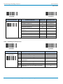
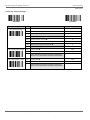
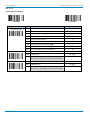
2.4.2 Symbology ID Transmission
PROGRAM
16
F_DEFAULT
Family Code Selection
P.C.
Parameter Selection
Symbology ID
SS
Disable symbology ID transmission
0
Transmission
SS
Enable prefix SICK symbology ID transmission
1
SS
Enable suffix SICK symbology ID transmission
2
SS
Enable both prefix and suffix SICK symbology ID
transmission
3
SS
Enable prefix AIM symbology ID transmission
4
SS
Enable suffix AIM symbology ID transmission
5
SS
Enable both prefix and suffix AIM symbology ID
transmission
6
© SICK AG · Germany · All rights reserved · Subject to change without notice
Option Code
8015906/2013-07-02
Symbology Reading Control
User Instructions
IDM corded
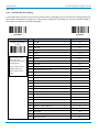
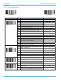
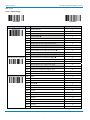
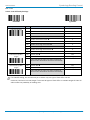
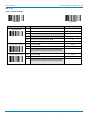
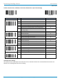
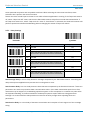
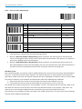
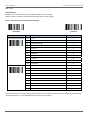
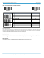
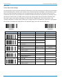
2.4.3 Readable Bar Code Setting
If your application is known, you may select those known symbologies only to increase the reading speed and
decrease the possibility of reading error. Furthermore, adding the “Symbology ID” into the transmitted data is
also helpful to identify the specific symbology.
PROGRAM
F_DEFAULT
Family Code Selection
P.C.
Readable Symbology
SS
Auto
00
Setting
CS
Code 128 *
01
CS
GS1-128
31
CS
UPC-A
02
CS
UPC-E *
03
CS
EAN-13 *
04
CS
EAN-8 *
05
CS
Codabar/NW-7 *
06
CS
Code 39 *
07
CS
Trioptic Code 39
47
CS
Standard/Industrial 2 of 5
08
CS
Matrix 2 of 5
38
CS
Interleaved 2 of 5 *
48
CS
China Postal Code
58
CS
Germany Postal Code
68
CS
Code 93 *
09
CS
Code 11
10
CS
MSI/Plessey
11
CS
UK/Plessey
12
CS
Telepen
13
CS
GS1 DataBar (RSS-14) *
14
CS
IATA
15
CS
Coupon Code
16
CS
PDF417 * /Micro PDF417
17
CS
Codablock F
18
CS
Code 16K
19
CS
Code 49
20
CS
Korea Post Code
21
Remember to scan
“FIN“ after you
terminate this section
(Cycling Scan).
If you choose “Auto”
(Single Scan) you
don’t need to scan
“FIN”.
8015906/2013-07-02
Parameter Selection
Option Code
© SICK AG · Germany · All rights reserved · Subject to change without notice
17
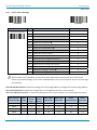
Symbology Reading Control
User Instructions
IDM corded
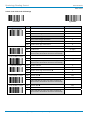
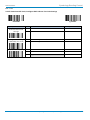
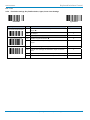
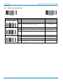
PROGRAM
Family Code Selection
F_DEFAULT
P.C.
Parameter Selection
Option Code
Readable Symbology
CS
QR Code */ Micro QR Code *
A0
Setting
CS
Data Matrix *
A1
CS
Aztec Code *
A3
CS
Australian Post
B0
CS
British Post
B1
CS
Intelligent Mail barcode
B3
CS
Japanese Post
B4
CS
KIX Post
B5
CS
Planet Code
B6
CS
Postnet
B8
Above symbologies marked with * are enabled as default. When you select “Auto”, the scanner only reads
those symbologies marked with *. When you set the minimum and maximum length of each symbology,
please note the data length of the scanned bar code doesn’t include start/stop characters.
18
© SICK AG · Germany · All rights reserved · Subject to change without notice
8015906/2013-07-02
Symbology Reading Control
User Instructions
IDM corded
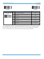
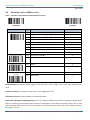
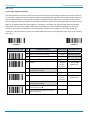
2.4.4 Code 39/ Code 32 Settings
PROGRAM
F_DEFAULT
Family Code Selection
P.C.
Code 39 Family Setting
SS
Disable Code 39
0
SS
Enable Code 39
1
SS
Select Standard Code 39 as primary format
2
SS
Select Full ASCII Code 39 as primary format
3
SS
Select Code 32 (PARAF, Italian Pharmaceutical) as
primary format
4
SS
Disable start/stop symbol transmission
5
SS
Enable start/stop symbol transmission
6
SS
Disable Code 32 leading A transmission
7
SS
Enable Code 32 leading A transmission
8
SS
Disable MOD 43 check digit verification
9
SS
Enable MOD 43 check digit verification
A
SS
Disable check digit transmission
B
SS
Enable check digit transmission
C
SS
Disable Code 39 buffering
D
SS
Enable Code 39 buffering
E
SS
Disable Trioptic Code 39
0
SS
Enable Trioptic Code 39
1
SS
Default (01)
MS
01-Maximum
Trioptic Code 39 Setting
Code 39 Min. Length
Parameter Selection
Option Code
FIN
(2 digits)
Scan 2 digits from the option code chart in the Appendix;
then the scanner will terminate this selection automatically.
Code 39 Max. Length
SS
Default (98)
MS
98-Minimum
FIN
(2 digits)
Scan 2 digits from the option code chart in the Appendix;
then the scanner will terminate this selection automatically.
Trioptic Code 39 and Code 39 Full ASCII cannot be enabled simultaneously.
8015906/2013-07-02
© SICK AG · Germany · All rights reserved · Subject to change without notice
19
Symbology Reading Control
User Instructions
IDM corded
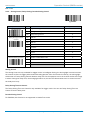
2.4.5 Code 39 Settings
PROGRAM
F_DEFAULT
Family Code Selection
P.C.
Parameter Selection
Option Code
Code 39 Security Level
SS
Level 0
0
SS
Level 1
1
SS
Level 2
2
SS
Level 3
3
Code 39 Security Level
The scanner offers four levels of decode security for Code 39 bar codes:
Level 0: If you are experiencing misread of poorly-printed or serious out-of-spec. bar codes in level 1
please select level 0.
Level 1: If you are experiencing misread of poorly-printed or out-of-spec. bar codes in level 2, please
select level 1.
Level 2: This is the default setting which allows the scanner to operate fastest, while providing
sufficient security in decoding “in-spec” Code 39 bar codes.
Level 3: If you failed to read poorly-printed or out-of-spec. bar codes in level 2, please select level 3.
This is the most aggressive setting and may increase the misread.
20
© SICK AG · Germany · All rights reserved · Subject to change without notice
8015906/2013-07-02
Symbology Reading Control
User Instructions
IDM corded
2.4.6 Codabar/ NW-7 Settings
PROGRAM
F_DEFAULT
Family Code Selection
P.C.
Codabar Settings
SS
Disable Codabar
0
SS
Enable Codabar
1
SS
Select Codabar standard format
2
SS
Select Codabar ABC format
3
SS
Select Codabar CLSI format
4
SS
Select Codabar CX format
5
SS
Disable start/stop symbol transmission
6
SS
Enable ABCD/ABCD start/stop symbol transmission
7
SS
Enable abcd/abcd start/stop symbol transmission
8
SS
Enable ABCD/TN*E start/stop symbol transmission
9
SS
Enable abcd/tn*e start/stop symbol transmission
A
SS
Disable check digit verification
B
SS
Enable check digit verification
C
SS
Disable check digit transmission
D
SS
Enable check digit transmission
E
Codabar Check Digit
SS
Modulus 16
0
Settings
SS
Modulus 10/weight 3
1
SS
Modulus 11
2
SS
Modulus 10/weight 2
3
SS
7 check DR
4
SS
Weight Modulus 11
5
SS
Runes (Modulus 10/weight 2)
6
SS
Default (04)
MS
01-Maximum
Codabar Min. Length
Parameter Selection
Option Code
FIN
(2 digits)
Scan 2 digits from the option code chart in the Appendix;
then the scanner will terminate this selection automatically.
Codabar Max. Length
SS
Default (98)
MS
98-Minimum
FIN
(2 digits)
Scan 2 digits from the option code chart in the Appendix;
then the scanner will terminate this selection automatically.
8015906/2013-07-02
© SICK AG · Germany · All rights reserved · Subject to change without notice
21
Symbology Reading Control
User Instructions
IDM corded
2.4.7 UPC-A/ UPC-E Settings
PROGRAM
F_DEFAULT
Family Code Selection
P.C.
Parameter Selection
Option Code
UPC-A Family Settings
SS
Disable UPC-A
0
SS
Enable UPC-A
1
SS
Disable UPC-E
2
SS
Enable UPC-E
3
SS
Disable UPC-E expansion
4
SS
Enable UPC-E expansion
5
SS
Disable UPC standardization
6
SS
Enable UPC standardization
7
SS
Disable UPC numeric system
8
SS
Enable UPC numeric system
9
SS
Disable UPC-A check digit transmission
A
SS
Enable UPC-A check digit transmission
B
SS
Disable UPC-E check digit transmission
C
SS
Enable UPC-E check digit transmission
D
SS
Disable UPC “leading 1” portion
E
SS
Enable UPC “leading 1” portion
F
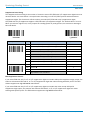
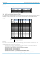
When enable UPC-E expansion, the UPC-E decoded data will be converted to UPC-A format and
affected by related settings, such as UPC standardization, UPC numeric system and UPC-A check digit
transmission.
UPC-E & EAN-8 Expansion: Expand the 8-digit UPC-E and 8-digit ENA-8 to 12-digit UPC-A and 13-digit EAN-13.
UPC-A Standardization: Expand the 12-digit UPC-A to 13-digit EAN-13 with 1 zero insertion.
UPC Lead 1 Numeric System: To read UPC leading with the 1 numeric system, you must enable this option.
22
WPC Selection
(UPC/EAN/CAN)
Basic
Length
Disable
Check
Digit
Disable
Numeric
System
With 2-digit
Addendum
With 5-digit
Addendum
Enable
Standardization
Enable
Expansion
UPC-A
12
-1
-1
+2
+5
+1
0
UPC-E
8
-1
-1
+2
+5
+1
+4
EAN-13
13
-1
NC
+2
+5
NC
0
EAN-8
8
-1
NC
+2
+5
NC
+5
© SICK AG · Germany · All rights reserved · Subject to change without notice
8015906/2013-07-02
Symbology Reading Control
User Instructions
IDM corded
PROGRAM
F_DEFAULT
Family Code Selection
P.C.
UPC Supplement Settings
SS
Select UPC without supplement digits
0
SS
Select UPC with only 2 supplement digits
1
SS
Select UPC with only 5 supplement digits
2
SS
Select UPC with 2/5 supplement digits
3
SS
Disable force supplement digits output
4
SS
Enable force supplement digits output
5
SS
UPC Family Addenda Separator Off
6
SS
UPC Family Addenda Separator On
7
SS
Level 0
0
SS
Level 1
1
SS
Level 2
2
UPC/ EAN Security Level
Parameter Selection
Option Code
Only available for UPC-A & EAN-13
Supplement Scan Vorting
SS
None
0
SS
Level 1
1
SS
Level 2
2
SS
Level 3
3
SS
Level 4
4
SS
Level 5
5
SS
Level 6
6
SS
Level 7
7
SS
Level 8
8
SS
Level 9
9
SS
Level 10
A
SS
Level 11
B
SS
Level 12
C
SS
Level 13
D
UPC/EAN Security Level
The scanner offers three levels of decode security for UPC/EAN bar codes:
Level 0: If you are experiencing misread of poorly-printed or out-of-spec. bar codes, especially in
characters 1, 2, 7, and 8 in level 1, please select level 0. Selection of this security level may
significantly impair the decoding ability of the scanner.
8015906/2013-07-02
© SICK AG · Germany · All rights reserved · Subject to change without notice
23
Symbology Reading Control
User Instructions
IDM corded
Level 1: This is the default setting which allows the scanner to operate fastest, while providing
sufficient security in decoding “in-spec” UPC/EAN bar codes.
Level 2: If you are experiencing misread of poorly-printed, soiled or damage bar codes in level 1,
please select level 2. This is the most aggressive setting and may increase the misread.
Supplement Scan Voting
The Supplement Scan Voting is the number of times the same UPC/EAN with 2/5 supplement digits has to be
decoded before it is transmitted. It is helpful when decoding a mix of UPC/EAN symbols with and without
supplement digits. This function is effective when you select UPC/EAN with only 2 supplement digits,
UPC/EAN with only 5 supplement digits or UPC/EAN with 2/5 supplement digits. The default value is Level 3.
When you select a higher level, it may impact the reading speed on poorly-printed, low contrast or damaged
barcode labels.
24
© SICK AG · Germany · All rights reserved · Subject to change without notice
8015906/2013-07-02
Symbology Reading Control
User Instructions
IDM corded
2.4.8 EAN Settings
PROGRAM
F_DEFAULT
Family Code Selection
P.C.
EAN Settings
SS
Disable EAN-13
0
SS
Enable EAN-13
1
SS
Disable EAN-8
2
SS
Enable EAN-8
3
SS
Disable EAN-8 expansion
4
SS
Enable EAN-8 expansion
5
SS
Disable EAN-13 check digit transmission
6
SS
Enable EAN-13 check digit transmission
7
SS
Disable EAN-8 check digit transmission
8
SS
Enable EAN-8 check digit transmission
9
SS
Disable ISBN/ISSN Conversion reading check
A
SS
Enable ISBN/ISSN Conversion reading check
B
SS
Select EAN without supplement digits
0
SS
Select EAN with only 2 supplement digits
1
SS
Select EAN with only 5 supplement digits
2
SS
Select EAN with 2/5 supplement digits
3
SS
Disable force supplement digits output
4
SS
Enable force supplement digits output
5
SS
EAN Addenda Separator Off
6
SS
EAN Addenda Separator On
7
SS
None
0
SS
Level 1
1
SS
Level 2
2
SS
Level 3
3
SS
Level 4
4
SS
Level 5
5
SS
Level 6
6
SS
Level 7
7
SS
Level 8
8
SS
Level 9
9
SS
Level 10
A
SS
Level 11
B
SS
Level 12
C
SS
Level 13
D
EAN Supplement Settings
Supplement Scan Vorting
8015906/2013-07-02
Parameter Selection
Option Code
© SICK AG · Germany · All rights reserved · Subject to change without notice
25
Symbology Reading Control
User Instructions
IDM corded
Supplement Scan Voting
The Supplement Scan Voting is the number of times the same UPC/EAN with 2/5 supplement digits has to be
decoded before it is transmitted. It is helpful when decoding a mix of UPC/EAN symbols with and without
supplement digits. This function is effective when you select UPC/EAN with only 2 supplement digits,
UPC/EAN with only 5 supplement digits or UPC/EAN with 2/5 supplement digits. The default value is Level 3.
When you select a higher level, it may impact the reading speed on poorly-printed, low contrast or damaged
barcode labels.
PROGRAM
F_DEFAULT
Family Code Selection
P.C.
Parameter Selection
Option Code
EAN Supplement Control
SS
Disable all specific prefix supplement digital output
0
SS
Enable all specific prefix supplement digital output
1
SS
Enable 491 Supplement Digit Output
2
SS
Enable 978/979 Supplement Digit Output
3
SS
Enable 977 Supplement Digit Output
4
SS
Enable 378/379 Supplement Digit Output
5
SS
Enable 414/419 Supplement Digit Output
6
SS
Enable 434/439 Supplement Digit Output
7
SS
Level 0
0
SS
Level 1
1
SS
Level 2
2
UPC/ EAN Security Level
Only available for UPC-A & EAN-13
EAN Supplement Control
If you select EAN with only 2 or 5 or 2/5 supplement digits and enable 491 prefix supplement digit output, the
scanner will transmit EAN with 2, or 5 or 2/5 supplement digits bar codes starting with 491 prefix. The EAN
without supplement digit will not be transmitted.
If you select EAN with only 2 or 5 or 2/5 supplement digits and enable the other except 491 prefix
supplement digit output, the scanner will transmit EAN with 2, or 5, or 2/5 supplement digits bar codes
starting with specific prefix. The EAN without supplement digit will be transmitted.
26
© SICK AG · Germany · All rights reserved · Subject to change without notice
8015906/2013-07-02
Symbology Reading Control
User Instructions
IDM corded
UPC/EAN Security Level
The scanner offers three levels of decode security for UPC/EAN bar codes:
Level 0: If you are experiencing misread of poorly-printed or out-of-spec. bar codes, especially in
characters 1, 2, 7, and 8 in level 1, please select level 0. Selection of this security level may
significantly impair the decoding ability of the scanner.
Level 1: This is the default setting which allows the scanner to operate fastest, while providing
sufficient security in decoding “in-spec” UPC/EAN bar codes.
Level 2: If you are experiencing misread of poorly-printed, soiled or damage bar codes in level 1,
please select level 2. This is the most aggressive setting and may increase the misread.
2.4.9 UCC Coupon Extended Code Settings
PROGRAM
F_DEFAULT
Family Code Selection
P.C.
Parameter Selection
Option Code
UCC Coupon Extended
SS
Disable UCC Coupon Extended Code
0
Code Setting
SS
Enable UCC Coupon Extended Code
1
UCC Coupon Extended Code
When UCC coupon extended code function is enabled, scanner decodes UPC-A barcodes starting with digit
“5”, EAN-13 barcodes starting with digit “99” and GS1-128 Coupon Codes. UPC-A, EAN-13 and EAN-128 must
be enabled to scan all types of Coupon Codes.
8015906/2013-07-02
© SICK AG · Germany · All rights reserved · Subject to change without notice
27
Symbology Reading Control
User Instructions
IDM corded
2.4.10 IATA & Interleaved 2 of 5 Settings
PROGRAM
28
F_DEFAULT
Family Code Selection
P.C.
Parameter Selection
IATA Settings
SS
Disable IATA
0
SS
Enable IATA
1
SS
Select 15-digit fixed length IATA checking
2
SS
Select variable length IATA
3
SS
Disable check digit verification
4
SS
Enable check digit automatic verification
5
SS
Enable S/N checking digit verification only
6
SS
Enable CPN checking digit verification only
7
SS
Enable CPN, Airline and S/N check digit verification
8
SS
Disable check digit transmission
9
SS
Enable check digit transmission
A
SS
Disable start/stop symbol transmission
B
SS
Enable start/stop symbol transmission
C
Interleaved 2 of 5
SS
Disable Interleaved 2 of 5
0
Settings
SS
Enable Interleaved 2 of 5
1
SS
Select Interleaved 2 of 5 as primary format
2
SS
Select German Postal Code as primary format
3
SS
No check character
4
SS
Validate USS check digit
5
SS
Validate OPCC check digit
6
SS
Disable check digit transmission
7
SS
Enable check digit transmission
8
© SICK AG · Germany · All rights reserved · Subject to change without notice
Option Code
8015906/2013-07-02
Symbology Reading Control
User Instructions
IDM corded
2.4.11 Code 25 Family Settings
PROGRAM
F_DEFAULT
Family Code Selection
P.C.
Parameter Selection
Option Code
Code 25 Settings
SS
Disable Standard/Industrial 2 of 5
0
SS
Enable Standard/Industrial 2 of 5
1
SS
Disable Matrix 2 of 5
2
SS
Enable Matrix 2 of 5
3
SS
Disable China Postal Code
4
SS
Enable China Postal Code
5
SS
Disable check digit verification
6
SS
Enable check digit verification
7
SS
Disable check digit transmission
8
SS
Enable check digit transmission
9
Code 25 Family Min.
SS
Default (04)
Length
MS
01-Maximum
FIN
(2 digits)
Scan 2 digits from the option code chart in the Appendix;
then the scanner will terminate this selection automatically.
Code 25 Family Max.
SS
Default (98)
Length
MS
98-Minimum
FIN
(2 digits)
Scan 2 digits from the option code chart in the Appendix;
then the scanner will terminate this selection automatically.
For Code25 setting, we recommend you to select only one type of Code 25 or set the
maximum/minimum bar code length. To decode all types of Code 25 or to variable length of Code 25
will increase the possibility of reading error.
8015906/2013-07-02
© SICK AG · Germany · All rights reserved · Subject to change without notice
29
Symbology Reading Control
User Instructions
IDM corded
2.4.12 Code 11 & Code 93 Settings
PROGRAM
F_DEFAULT
Family Code Selection
P.C.
Code 11 Settings
SS
Disable Code 11
0
SS
Enable Code 11
1
SS
Disable check digit verification
2
SS
Select 1-check digit verification
3
SS
Select 2-check digit verification
4
SS
Disable check digit transmission
5
SS
Enable check digit transmission
6
SS
Default (04)
MS
01-Maximum
Code 11 Min. Length
Parameter Selection
Option Code
FIN
(2 digits)
Scan 2 digits from the option code chart in the Appendix;
then the scanner will terminate this selection automatically.
Code 11 Max. Length
SS
Default (98)
MS
98-Minimum
FIN
(2 digits)
Scan 2 digits from the option code chart in the Appendix;
then the scanner will terminate this selection automatically.
Code 39 Settings
Code 39 Min. Length
SS
Disable Code 93
0
SS
Enable Code 93
1
SS
Disable check digit transmission
2
SS
Enable check digit transmission
3
SS
Default (01)
MS
01-Maximum
FIN
(2 digits)
Scan 2 digits from the option code chart in the Appendix;
then the scanner will terminate this selection automatically.
Code 39 Max. Length
SS
Default (98)
MS
98-Minimum
FIN
(2 digits)
Scan 2 digits from the option code chart in the Appendix;
then the scanner will terminate this selection automatically.
30
© SICK AG · Germany · All rights reserved · Subject to change without notice
8015906/2013-07-02
Symbology Reading Control
User Instructions
IDM corded
2.4.13 MSI/ Plessey Settings
PROGRAM
F_DEFAULT
Family Code Selection
P.C.
MSI/ Plessey Settings
SS
Disable MSI/Plessey
0
SS
Enable MSI/Plessey
1
SS
Select MOD 10 check digit
2
SS
Select MOD 10-10 check digit
3
SS
Select MOD 11-10 check digit
4
SS
Disable check digit transmission
5
SS
Enable check digit transmission
6
SS
Default (04)
MS
01-Maximum
MSI/ Plessey Min. Length
Parameter Selection
Option Code
FIN
(2 digits)
Scan 2 digits from the option code chart in the Appendix;
then the scanner will terminate this selection automatically.
MSI/ Plessey Max.
SS
Default (98)
Length
MS
98-Minimum
FIN
(2 digits)
Scan 2 digits from the option code chart in the Appendix;
then the scanner will terminate this selection automatically.
8015906/2013-07-02
© SICK AG · Germany · All rights reserved · Subject to change without notice
31
Symbology Reading Control
User Instructions
IDM corded
2.4.14 Code 128 Settings
PROGRAM
F_DEFAULT
Family Code Selection
P.C.
Code 128 Settings
SS
Disable Code 128
0
SS
Enable Code 128
1
SS
ISBT Concatenation Off
2
SS
ISBT Concatenation On
3
SS
Default (01)
MS
01-Maximum
Code 128 Min. Length
Parameter Selection
Option Code
FIN
(2 digits)
Scan 2 digits from the option code chart in the Appendix;
then the scanner will terminate this selection automatically.
Code 128 Max. Length
SS
Default (98)
MS
98-Minimum
FIN
(2 digits)
Scan 2 digits from the option code chart in the Appendix;
then the scanner will terminate this selection automatically.
Code 128 Security Level
SS
Level 0
0
SS
Level 1
1
Code 128 Security Level
The scanner offers two levels of decode security for Code128 bar codes:
Level 0: If you are experiencing misread of poor-printed or out-of-spec. bar codes in level 1, please
select level 0.
Level 1: This is the default setting which allows the scanner to operate fastest, while providing
sufficient security in decoding "in-spec." Code 128 bar codes.
32
© SICK AG · Germany · All rights reserved · Subject to change without notice
8015906/2013-07-02
Symbology Reading Control
User Instructions
IDM corded
2.4.15 GS1-128 Settings
PROGRAM
F_DEFAULT
Family Code Selection
P.C.
GS1-128 Settings
SS
Disable GS1-128
0
SS
Enable GS1-128
1
SS
Default (01)
MS
01-Maximum
GS1-128 Min. Length
Parameter Selection
Option Code
FIN
(2 digits)
Scan 2 digits from the option code chart in the Appendix;
then the scanner will terminate this selection automatically.
GS1-128 Max. Length
SS
Default (98)
MS
98-Minimum
FIN
(2 digits)
Scan 2 digits from the option code chart in the Appendix;
then the scanner will terminate this selection automatically.
8015906/2013-07-02
© SICK AG · Germany · All rights reserved · Subject to change without notice
33
Symbology Reading Control
User Instructions
IDM corded
2.4.16 UK/ Plessey Settings
PROGRAM
F_DEFAULT
Family Code Selection
P.C.
UK/ Plessey Settings
SS
Disable UK/Plessey
0
SS
Enable UK/Plessey
1
SS
Select UK/Plessey Standard Format
2
SS
Select UK/Plessey CLSI Format
3
SS
Disable Convert X to A-F
4
SS
Enable Convert X to A-F
5
SS
Disable check digit transmission
6
SS
Enable check digit transmission
7
SS
Default (04)
MS
01-Maximum
UK/ Plessey Min. Length
Parameter Selection
Option Code
FIN
(2 digits)
Scan 2 digits from the option code chart in the Appendix;
then the scanner will terminate this selection automatically.
UK/ Plessey Max. Length
SS
Default (98)
MS
98-Minimum
FIN
(2 digits)
Scan 2 digits from the option code chart in the Appendix;
then the scanner will terminate this selection automatically.
34
© SICK AG · Germany · All rights reserved · Subject to change without notice
8015906/2013-07-02
Symbology Reading Control
User Instructions
IDM corded
2.4.17 Telepen Settings
PROGRAM
F_DEFAULT
Family Code Selection
P.C.
Telepen Settings
SS
Disable Telepen
0
SS
Enable Telepen
1
SS
Select Telepen Numeric mode
2
SS
Select Telepen Full ASCII mode
3
SS
Disable check digit transmission
4
SS
Enable check digit transmission
5
SS
Default (04)
MS
01-Maximum
Telepen Min. Length
Parameter Selection
Option Code
FIN
(2 digits)
Scan 2 digits from the option code chart in the Appendix;
then the scanner will terminate this selection automatically.
Telepen Max. Length
SS
Default (98)
MS
98-Minimum
FIN
(2 digits)
Scan 2 digits from the option code chart in the Appendix;
then the scanner will terminate this selection automatically.
8015906/2013-07-02
© SICK AG · Germany · All rights reserved · Subject to change without notice
35
Symbology Reading Control
User Instructions
IDM corded
2.4.18 GS1 DataBar Settings
PROGRAM
F_DEFAULT
Family Code Selection
P.C.
GS1 DataBar Settings
SS
Disable GS1 DataBar (RSS-14)
0
SS
Enable GS1 DataBar (RSS-14)
1
SS
Disable GS1 DataBar Limited
2
SS
Enable GS1 DataBar Limited
3
SS
Disable GS1 DataBar Expanded
4
SS
Enable GS1 DataBar Expanded
5
SS
Default (04)
MS
01-Maximum
GS1 DataBar Min. Length
Parameter Selection
Option Code
FIN
(2 digits)
Only available for Expanded GS1 DataBar.
Scan 2 digits from the option code chart in the Appendix;
then the scanner will terminate this selection automatically.
GS1 DataBar Max.
SS
Default (74)
Length
MS
74-Minimum
FIN
(2 digits)
Only available for Expanded GS1 DataBar.
Scan 2 digits from the option code chart in the Appendix;
then the scanner will terminate this selection automatically.
36
© SICK AG · Germany · All rights reserved · Subject to change without notice
8015906/2013-07-02
Symbology Reading Control
User Instructions
IDM corded
2.4.19 Composite Codes, Codablock F, PDF417, Micro PDF417 Settings
PROGRAM
F_DEFAULT
Family Code Selection
P.C.
Parameter Selection
Option Code
Composite Codes
SS
Disable composite codes
0
Settings
SS
Enable composite codes
1
SS
UPC Composite Mode: UPC never linked
2
SS
UPC Composite Mode: UPC always linked
3
If “UPC Composite Mode: UPC never linked” is selected, UPC
barcodes are transmitted whether Micro PDF417 symbol is
detected or not.
If “UPC Composite Mode: UPC always linked” is selected,
UPC barcodes are only transmitted when the Micro PDF417
is detected.
SS
Disable
0
SS
Enable
1
PDF417/ Micro PDF417
SS
Disable PDF417
0
Settings
SS
Enable PDF417
1
SS
Disable MicroPDF417
2
SS
Enable MicroPDF417
3
Codablock F Settings
8015906/2013-07-02
© SICK AG · Germany · All rights reserved · Subject to change without notice
37
Symbology Reading Control
User Instructions
IDM corded
2.4.20 Code 16K & Code 49 Settings
PROGRAM
F_DEFAULT
Family Code Selection
P.C.
Code 16K Settings
SS
Disable Code 16K
0
SS
Enable Code 16K
1
SS
Default (01)
FIN
MS
01-Maximum
Code 16K Min. Length
Parameter Selection
Option Code
(3 digits)
Scan 3 digits from the option code chart in the Appendix;
then the scanner will terminate this selection automatically.
Code 16K Max. Length
SS
Default (160)
MS
160-Minimum
FIN
(3 digits)
Scan 3 digits from the option code chart in the Appendix;
then the scanner will terminate this selection automatically.
Code 49 Settings
Code 49 Min. Length
SS
Disable Code 49
0
SS
Enable Code 49
1
SS
Default (01)
FIN
MS
01-Maximum
(2 digits)
Scan 2 digits from the option code chart in the Appendix;
then the scanner will terminate this selection automatically.
Code 49 Max. Length
SS
Default (81)
MS
81-Minimum
FIN
(2 digits)
Scan 2 digits from the option code chart in the Appendix;
then the scanner will terminate this selection automatically.
38
© SICK AG · Germany · All rights reserved · Subject to change without notice
8015906/2013-07-02
Symbology Reading Control
User Instructions
IDM corded
2.4.21 QR Code Settings
PROGRAM
F_DEFAULT
Family Code Selection
P.C.
QR Code Settings
SS
Disable QR Code
0
SS
Enable QR Code
1
SS
Disable MicroQR Code
2
SS
Enable MicroQR Code
3
SS
Disable QR Code Append
4
SS
Enable QR Code Append
5
SS
Disable QR Code Inverse Reading
6
SS
Enable QR Code Inverse Reading
7
SS
Auto detect QR Code Inverse Reading
8
SS
Default (01)
MS
01-Maximum
QR Code Min. Length
Parameter Selection
Option Code
FIN
(4 digits)
Scan 4 digits from the option code chart in the Appendix;
then the scanner will terminate this selection automatically.
QR Code Max. Length
SS
Default (7089)
MS
7089-Minimum
FIN
(4 digits)
Scan 4 digits from the option code chart in the Appendix;
then the scanner will terminate this selection automatically.
8015906/2013-07-02
© SICK AG · Germany · All rights reserved · Subject to change without notice
39
Symbology Reading Control
User Instructions
IDM corded
2.4.22 Data Matrix Settings
PROGRAM
F_DEFAULT
Family Code Selection
P.C.
Data Matrix Settings
SS
Disable Data Matrix
0
SS
Enable Data Matrix
1
SS
Disable Data Matrix Inverse Reading
4
SS
Enable Data Matrix Inverse Reading
5
SS
Auto Detect Data Matrix Inverse Reading
6
SS
Disable Data Matrix Mirror Images
7
SS
Enable Data Matrix Mirror Images
8
SS
Auto Detect Data Matrix Mirror Images
9
SS
Default (01)
MS
01-Maximum
Data Matrix Min. Length
Parameter Selection
Option Code
FIN
(4 digits)
Scan 4 digits from the option code chart in the Appendix;
then the scanner will terminate this selection automatically.
Data Matrix Max. Length
SS
Default (3116)
MS
3116-Minimum
FIN
(4 digits)
Scan 4 digits from the option code chart in the Appendix;
then the scanner will terminate this selection automatically.
40
© SICK AG · Germany · All rights reserved · Subject to change without notice
8015906/2013-07-02
Symbology Reading Control
User Instructions
IDM corded
2.4.23 Aztec Code Settings
PROGRAM
F_DEFAULT
Family Code Selection
P.C.
Aztec Code Settings
SS
Disable Aztec Code
0
SS
Enable Aztec Code
1
SS
Default (01)
MS
01-Maximum
Aztec Code Min. Length
Parameter Selection
Option Code
FIN
(4 digits)
Scan 4 digits from the option code chart in the Appendix;
then the scanner will terminate this selection automatically.
Aztec Code Max. Length
SS
Default (3832)
MS
3832-Minimum
FIN
(4 digits)
Scan 4 digits from the option code chart in the Appendix;
then the scanner will terminate this selection automatically.
8015906/2013-07-02
© SICK AG · Germany · All rights reserved · Subject to change without notice
41
Symbology Reading Control
User Instructions
IDM corded
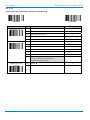
2.4.24 Autralian Post, US Planet, US Postnet, British Post, Japan Post Settings
PROGRAM
F_DEFAULT
Family Code Selection
P.C.
Australian Post Settings
SS
Disable Australian Post
0
SS
Enable Australian Post
1
SS
Raw format Output
2
SS
Numeric Encoding Output (N Encoding Table)
3
SS
Alphanumeric Encoding Output (C Encoding Table)
4
SS
Auto-discriminate Output (Combination C & N
Encoding Table)
5
SS
Disable US Planet
0
SS
Enable US Planet
1
SS
Disable Check Digit Transmission
2
SS
Enable Check Digit Transmission
3
SS
Disable US Postnet
0
SS
Enable US Postnet
1
SS
Disable Check Digit Transmission
2
SS
Enable Check Digit Transmission
3
SS
Disable British Post
0
SS
Enable British Post
1
SS
Disable Check Digit Transmission
2
SS
Enable Check Digit Transmission
3
SS
Disable Japan Post
0
SS
Enable Japan Post
1
US Planet Settings
US Postnet Settings
British Post Settings
Japan Post Settings
Parameter Selection
Option Code
Australian Post Setting
Auto-discriminate output option increases the risk of misread because the encoded data format does not
specify the encoding table used for encoding.
42
© SICK AG · Germany · All rights reserved · Subject to change without notice
8015906/2013-07-02
Symbology Reading Control
User Instructions
IDM corded
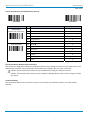
2.4.25 Netherland KIX Code, Intelligent Mail & Korea Post Code Settings
PROGRAM
F_DEFAULT
Family Code Selection
P.C.
Parameter Selection
Option Code
Netherlands KIX Code
SS
Disable Netherlands KIX Code
0
Settings
SS
Enable Netherlands KIX Code
1
Intelligent Mail Settings
SS
Disable Intelligent Mail
0
(USPS 4CB/ One Code)
SS
Enable Intelligent Mail
1
Korea Post Code Settings
SS
Disable Korea Post Code
0
SS
Enable Korea Post Code
1
Length fixed in 6 characters.
8015906/2013-07-02
© SICK AG · Germany · All rights reserved · Subject to change without notice
43
Keyboard Interface Control
User Instructions
IDM corded
2.5
Keyboard Interface Control
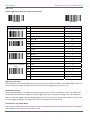
2.5.1 Keyboard Layout (Language) Settings
PROGRAM
F_DEFAULT
Family Code Selection
P.C.
Parameter Selection
Option Code
Keyboard Layout
SS
USA (QWERTY)
00
SS
France (AZERTY)
01
SS
Germany (QWERTZ)
02
SS
United Kingdom (QWERTY)
03
SS
Canadian French (QWERTY)
04
SS
Spain (Spanish, QWERTY)
05
SS
Sweden/Finland (QWERTY)
06
SS
Portugal (QWERTY)
07
SS
Norway (QWERTY)
08
SS
Spain (Latin America, QWERTY)
09
SS
Italy (QWERTY)
10
SS
Netherlands (QWERTY)
11
SS
Denmark (QWERTY)
12
SS
Belgium (AZERTY)
13
SS
Switzerland-Germany (QWERTZ)
14
SS
Iceland (QWERTY)
15
SS
Japan (DOS/V)
16
SS
Czech (QWERTY)
17
Please refer to the ASCII/HEX Table listed in the Appendix to determine the HEX codes for characters,
symbols, and functions to be used as preamble or postamble.
To set preamble or postamble as function key output, you must enable the “Function Key Emulation” feature
first.
Keyboard Interface Message String:
44
Preamble
Data Length
Prefix Symbol ID
Scanned Data
Suffix Symbol ID
Postamble
Record Suffix
1-15
characters
2-4 digits
1 or 3 characters
Variable
length
1 or 3 characters
1-15
characters
1 character
© SICK AG · Germany · All rights reserved · Subject to change without notice
8015906/2013-07-02
Keyboard Interface Control
User Instructions
IDM corded
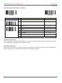
2.5.2 Record Suffix, Preamble, Postamble, FNC1 Transmit, Caps Lock
PROGRAM
F_DEFAULT
Family Code Selection
P.C.
Record Suffix
SS
None
0
SS
RETURN
1
SS
TAB
2
SS
SPACE
3
SS
ENTER (Numeric Key Pad)
4
SS
User defined character (1 character)
SS
None
MS
1-15 characters
Preamble
Parameter Selection
Option Code
5, (00-7F)
FIN
[00-7F], [FIN]
Maximum 15-character input.
Scan “FIN” to terminate this selection.
Postamble
SS
None
MS
1-15 characters
FIN
[00-7F], [FIN]
Maximum 15-character input.
Scan “FIN” to terminate this selection.
FNC1 Symbol Char.
SS
Disable
0
Transmit
SS
Enable
1
Caps Lock Control
SS
“Caps Lock Off” State
0
SS
“Caps Lock On” State
1
SS
Auto Detect (PC/AT, PS/2, Kerd Replacement and
DOS/V Machines only)
2
Caps Lock Release
SS
“Caps Lock On, Caps Off”
0
Control
SS
“Caps Lock On, Shift Off”
1
FNC1 Symbol Character. Transmit
When this function is enabled and the FNC1 is contained in the scanned data, the scanner transmits the
FNC1 to the host. When the scanner interface is set to keyboard, the scanned code is converted to
corresponding key function before it is transmitted.
The function of “Caps Lock Control” and “Key Pad Emulation” are only available for IBM PC/AT, PS/VP, PS/2
8015906/2013-07-02
© SICK AG · Germany · All rights reserved · Subject to change without notice
45
Keyboard Interface Control
User Instructions
IDM corded
series personal computers and compatible machines. While selecting the other host interfaces, these
selections don’t perform the above functions.
Please check the actual Caps Lock state in use while software application is running. If the Caps Lock state is
off, select “Caps Lock Off” state, and then the Hand-held scanner will perform normal data transmission. If
the Caps Lock state is on, select “Caps Lock On” state. If “Auto Detect” is selected, the Hand-held scanner will
perform special transmission handshaking without changing the status of Caps Lock switch.
2.5.3 Delay Settings
PROGRAM
F_DEFAULT
Family Code Selection
P.C.
Parameter Selection
Intermessage Delay
SS
None
MS
1-99 (x5) msec.
Option Code
FIN
(2 digits)
Scan 2 digits from the option code chart in the Appendix;
then the scanner will terminate this selection automatically.
Intercharacter Delay
SS
None
MS
1-99 (x5) msec.
FIN
(2 digits)
Scan 2 digits from the option code chart in the Appendix;
then the scanner will terminate this selection automatically.
Interfunction Delay
SS
None
MS
1-99 (x5) msec.
FIN
(2 digits)
Scan 2 digits from the option code chart in the Appendix;
then the scanner will terminate this selection automatically.
Intermessage Delay: is a time delay between messages outputted by the Hand-held scanner. Increasing this
delay will help host applications to process the incoming data on time.
Intercharacter Delay: is a time delay between data characters outputted by the Hand-held scanner. These two
parameters are used to synchronize data communication when: 1) the data transmission speed is too fast,
characters may be skipped; 2) multitasking operation system or host computers in a network may slow down
the keyboard handling; 3) various notebook or desktop PC systems require different timing parameter
settings. It is recommended to always add one extra unit as safety margin when adjusting these two
parameters.
Interfunction Delay: is a time delay of between transmission and reception of each segment of the message
string.
46
© SICK AG · Germany · All rights reserved · Subject to change without notice
8015906/2013-07-02
Keyboard Interface Control
User Instructions
IDM corded
2.5.4 Emulation Settings, Key Pad Emulation, Upper/Lower Case Settings
PROGRAM
F_DEFAULT
Family Code Selection
P.C.
Parameter Selection
Option Code
Function Key Emulation
SS
Enable ASCII 00-31 code as keyboard function code
output
0
SS
Ctrl-Output
1
Refer to Appendix – Keyboard Function Code Table for details.
Key Pad Emulation
Upper/ Lower Case
8015906/2013-07-02
SS
Disable key pad emulation
0
SS
Enable numeric output as key pad (Num Lock On)
output
1
SS
Normal case (neglect the upper/lower case control)
0
SS
Inverse case (change all characters output to inverse
case)
1
SS
Upper case (force all characters output as upper case)
2
SS
Lower case (force all characters output as lower case)
3
© SICK AG · Germany · All rights reserved · Subject to change without notice
47
Serial Interface Control
User Instructions
IDM corded
2.6
Serial Interface Control
2.6.1 Record Suffix, Preamble, Postamble Settings
PROGRAM
F_DEFAULT
Family Code Selection
P.C.
Parameter Selection
Option Code
STX/ ETX Control
SS
Disable STX/ETX transmission
0
SS
Enable STX/ETX transmission
1
STX/ETX are two characters used to indicate the starting and
ending of the total data frame transmitted via serial
interface.
Record Suffix
Preamble
SS
None
0
SS
CR (0DH)
1
SS
LF (0AH)
2
SS
CRLF (0D0AH)
3
SS
TAB (09H)
4
SS
SPACE (20H)
5
SS
None
MS
1-15 characters
FIN
[00-7F], [FIN]
Maximum 15-character input; scan “FIN” to terminate this
selection.
Postamble
SS
None
FIN
MS
1-15 characters
[00-7F], [FIN]
Maximum 15-character input; scan “FIN” to terminate this
selection.
FNC1 Symbol Char.
Transmit
SS
Disable
0
SS
Enable
1
When this function is enabled and the FNC1 is contained in
scanned data, the scanner transmits the FNC1 to the host. A
chart of the FNC1 is provided in the Appendix – Keyboard
Function Code Table. When the scanner interface is set to
keyboard, the scanned code is converted to corresponding
key function before it is transmitted.
Serial Interface Message String (RS-232, USB COM)
48
STX
Preamble
1
character
1-15
characters
Data
Length
2-4
digits
Prefix
Symbol ID
1 or 3
characters
Scanned
Data
Variable
length
Suffix
Symbol ID
1 or 3
characters
Postamble
ETX
1-15
characters
1
character
© SICK AG · Germany · All rights reserved · Subject to change without notice
Record
Suffix
1
character
8015906/2013-07-02
Serial Interface Control
User Instructions
IDM corded
2.6.2 Delay Settings
PROGRAM
F_DEFAULT
Family Code Selection
P.C.
Parameter Selection
Intermessage Delay
SS
None
MS
1-99 (x5) msec.
Option Code
FIN
(2 digits)
Scan 2 digits from the option code chart in the Appendix;
then the scanner will terminate this selection automatically.
Intercharacter Delay
SS
None
MS
1-99 (x5) msec.
FIN
(2 digits)
Scan 2 digits from the option code chart in the Appendix;
then the scanner will terminate this selection automatically.
Interfunction Delay
SS
None
MS
1-99 (x5) msec.
FIN
(2 digits)
Scan 2 digits from the option code chart in the Appendix;
then the scanner will terminate this selection automatically.
Intermessage Delay: is a time delay between messages outputted by the Hand-held scanner. Increasing this
delay will help host applications to process the incoming data on time.
Intercharacter Delay: is a time delay between data characters outputted by the Hand-held scanner. These two
parameters are used to synchronize data communication when: 1) the data transmission speed is too fast,
characters may be skipped; 2) multitasking operation system or host computers in a network may slow down
the keyboard handling; 3) various notebook or desktop PC systems require different timing parameter
settings. It is recommended to always add one extra unit as safety margin when adjusting these two
parameters.
Interfunction Delay: is a time delay of between transmission and reception of each segment of the message
string.
8015906/2013-07-02
© SICK AG · Germany · All rights reserved · Subject to change without notice
49
Serial Interface Control
User Instructions
IDM corded
2.6.3 Protocol, ACK/ NAK Settings
PROGRAM
F_DEFAULT
Family Code Selection
P.C.
Handshaking Protocol
SS
None (free running mode)
0
SS
RTS/CTS (hardware handshaking)
1
SS
ACK/NAK (software handshaking)
2
SS
Xon/Xoff (software handshaking)
3
SS
3 times
FIN
SS
0-255 times
(3 digits)
SS
Disable ACK Time-out Indication
0
SS
Enable ACK Time-out Indication
1
SS
Disable ACK Indication
2
SS
Enable ACK Indication
3
NAK Retry Count
ACK Indication
Parameter Selection
Option Code
USB COM doesn’t support RTS/CTS handshaking protocol.
When the RTS/CTS Hardware Handshaking option is selected, the RTS (request to send) and CTS
(clear to send) signals will be issued before normal data communication. This option is very helpful to
ensure the reliability of data communication.
When the ACK/NAK Software Handshaking option is selected, the Hand-held scanner waits for an
ACK (acknowledge) or NAK (not acknowledge) from the host computer after each data transmission. If
the NAK is received, the Hand-held scanner will re-send the data until receiving ACK.
NAK Retry Count
After transmitting data, the scanner expects a NAK response from the host up to the preset “Serial Response
Time-out”. If the scanner doesn’t get a response, the scanner will issue an error indication and discard the
data. When a NAK is received, the scanner transmits the same data again and waits for either an ACK or NAK.
The scanner issues an error indication and discards the data under following two conditions:
1. After preset NAK retry counts is received within the preset serial response time-out.
2. If the preset time-out is up but the preset NAK retry counts haven’t come to the end.
The default retry counts are three times. If you program “0 times”, the scanner will not resend the data to the
host when the scanner receives a NAK. The scanner will discard the data. If you program “255 times”, the
scanner can receive unlimited NAKs from the host within the pre-set serial response time-out.
This function is not available for batch mode. When you enable this function in on-line mode, the out-of-range
function will be disabled automatically.
50
© SICK AG · Germany · All rights reserved · Subject to change without notice
8015906/2013-07-02
Serial Interface Control
User Instructions
IDM corded
ACK Indication
Disable: There’s neither LED nor beeping indication for this setting.
Enable: There’s a specific LED and beeping indication for this setting.
2.6.4 Response Time-out, Baud Rate Settings
PROGRAM
F_DEFAULT
Family Code Selection
P.C.
Serial Response Time-out
SS
None
0
SS
200 mseconds
1
SS
500 mseconds
2
SS
800 mseconds
3
SS
1 second
4
SS
2 seconds
5
SS
3 seconds
6
SS
4 seconds
7
SS
5 seconds
8
SS
8 seconds
9
SS
10 seconds
A
SS
38.4K BPS
0
SS
19.2K BPS
1
SS
9600 BPS
2
SS
4800 BPS
3
SS
2400 BPS
4
SS
1200 BPS
5
SS
57.6K BPS
6
SS
115.2K BPS
7
SS
38.4K BPS
8
SS
19.2K BPS
9
Baud Rate (BPS)
Parameter Selection
Option Code
The Serial Response Time-out is a pre-defined delay time for the Hand-held scanner to wait for handshaking,
acknowledgment or non-acknowledgment from the host computer
8015906/2013-07-02
© SICK AG · Germany · All rights reserved · Subject to change without notice
51
Serial Interface Control
User Instructions
IDM corded
2.6.5 Data Frame Settings
PROGRAM
52
F_DEFAULT
Family Code Selection
P.C.
Parameter Selection
Data Frame
SS
8, None, 1
0
SS
8, Odd, 1
1
SS
8, Even, 1
2
SS
8, Space, 1
3
SS
8, Mark, 1
4
SS
8, None, 2
5
SS
7, Odd, 1
6
SS
7, Even, 1
7
SS
7, Space, 1
8
SS
7, Mark, 1
9
SS
7, None, 2
A
SS
7, Odd, 2
B
SS
7, Even, 2
C
© SICK AG · Germany · All rights reserved · Subject to change without notice
Option Code
8015906/2013-07-02
Wand/ Laser Emulation Control (IDM1xx series)
User Instructions
IDM corded
2.7
Wand/ Laser Emulation Control (IDM1xx series)
2.7.1 Output Polarity, Signal State, Margin/ Module Time
PROGRAM
F_DEFAULT
Family Code Selection
P.C.
Parameter Selection
Option Code
Output Polarity
SS
High level (5Vdc) on Bar (low level on Space)
0
SS
Low level (0Vdc) on Bar (high level on Space)
1
Determine the output voltage level for both bar and space.
Initial Signal State
SS
High Level (5Vdc)
0
SS
Low Level (0Vdc)
1
Determine the initial state of output voltage level.
SS
10 msec.
0
SS
15 msec.
1
SS
20 msec.
2
SS
25 msec.
3
SS
30 msec.
4
SS
Extremely short
0
SS
Short
1
SS
Medium
2
SS
Long
3
SS
1:2
0
SS
1:2.5
1
SS
1:3
2
Code 39/ Code 128
SS
Disable standard Code 39 emulation
0
Emulation
SS
Enable standard Code 39 skip emulation
1
SS
Enable standard Code 39 replace emulation
2
SS
Enable Full ASCII Code 39 emulation
3
SS
Enable Code 128 emulation
4
Margin Time
Module Time
Narrow/ Wide ratio
Code 39 Skip
When this option is selected, all scanned data will be translated as Standard Code 39 wand/laser emulation
output. If any lower case characters are read, they will be translated to upper case characters. Any other
characters that are not available in Code 39 symbology set will be skipped.
Code 39 Replace
Any character not normally available in the standard Code 39 symbology set, will be translated as Space.
8015906/2013-07-02
© SICK AG · Germany · All rights reserved · Subject to change without notice
53
Operation Control (IDM1xx series)
User Instructions
IDM corded
2.8
Operation Control (IDM1xx series)
2.8.1 Operation Mode Setting
PROGRAM
F_DEFAULT
Family Code Selection
P.C.
Parameter Selection
Option Code
Operation Mode
SS
Low Power mode
0
SS
Trigger mode
1
SS
Presentation mode
2
SS
Alternative mode
3
SS
Flash mode
4
SS
Force mode
5
SS
Toggle mode
6
SS
Diagnostic mode
7
SS
Level mode
8
Low Power Mode (Low Power Triggering)
The scanner goes into idle state after scanning the barcode. You must press the trigger to wake up the
scanner for operation. It is very helpful for mobile data collection and applications, which are concerned with
power saving.
Trigger Mode (External Triggering)
The scanner goes into standby state after scanning the barcode. You must press the trigger to turn on the
light source of the scanner before scanning the bar code.
Presentation Mode (Auto Detection)
Presentation mode uses ambient light to detect the barcodes. The light source is off until the scanner detects
an image which is similar to a barcode. Then the light source turns on automatically to read the bar code. If
the light level in the room is not high enough, Presentation Mode may not work properly. You can choose
different level of “Presentation Sensitivity” to meet your application’s requirements. (Please refer to the
setting of “Presentation Sensitivity” on page 68.)
Alternative Mode (Periodic Power Off)
The scanner keeps the light source of the scanner turned on till the pre-defined light source on time is up.
After the scanner turns off the light source, you must press the trigger to turn on the light source again. After
each good read, the timer counter of “Light Source on Time” is reset. For you do not have to press the trigger
frequently it is very convenient for multiple scanning.
54
© SICK AG · Germany · All rights reserved · Subject to change without notice
8015906/2013-07-02
User Instructions
Operation Control (IDM1xx series)
IDM corded
Flash Mode (Pulse Driven Reading)
The scanner flashes the light source of the scanner without using the trigger. If the scanner detects an image
which is similar to a barcode, the scanner forces on the light source automatically and scans the barcode.
Flash Duty Cycle adjustment can change the frequency of the blinking.
Force Mode (Continued Power On)
The light source of the scanner is forced on for continued operation without pressing the trigger button. This
mode is convenient for high speed bar code reading.
Toggle Mode (Repeat Reading)
The toggle mode is very similar to the Alternative Mode but without the pre-defined light source on time
concern. You must press the trigger to turn on the light source of the scanner to scan. The scanner keeps the
light source turned on until you press the trigger again.
Diagnostic Mode (Test Reading)
This operation mode is specifically designed for diagnostic purposes. When this operation mode is selected,
the light source of the scanner is force on without regard for other programmable parameters, such as reread
delay, redundancy, and so forth.
Level Mode (Auto Power Off)
When this operation mode is selected, the scanner continues to turn on the light source of the scanner before
a good read or pre-defined “Light Source on Time”. If the scanner decodes a barcode successfully, it turns off
the light source immediately. After the scanner turns off the light source, you must press the trigger to turn on
the light source again. If there is no scanning operation performed during the pre-defined light source on time,
the scanner enters the idle state after the pre-defined light source on time is up.
8015906/2013-07-02
© SICK AG · Germany · All rights reserved · Subject to change without notice
55
Operation Control (IDM1xx series)
User Instructions
IDM corded
2.8.2 Presentation Control, Scan Rate, Flash Duty
PROGRAM
F_DEFAULT
Family Code Selection
P.C.
Presentation Control
SS
Presentation mode
0
SS
Flash mode
1
SS
Force mode
2
SS
Dynamic
0
SS
Fixed
1
SS
1/2 duty cycle
0
SS
2/3 duty cycle
1
SS
3/4 duty cycle
2
SS
4/5 duty cycle
3
Scan Rate Control
Flash Duty Cycle
Parameter Selection
Option Code
Presentation Control
When the scanner is placed on the Hands-free stand, the scanner will be switched from hand-held scanning to
hands-free scanning automatically. Three hands-free scanning modes are available. You are recommended to
use flash mode or force mode while under insufficient ambient light.
Scan Rate Control
The scanner will have better motion tolerance when you select “Fixed” scan rate. It’s suitable for applications
which need higher motion tolerance on the move. But this may impact to the reading distance.
Flash Duty Cycle
The Flash Duty Cycle is designed to control the flashing frequency of the light source.
56
© SICK AG · Germany · All rights reserved · Subject to change without notice
8015906/2013-07-02
Operation Control (IDM1xx series)
User Instructions
IDM corded
2.8.3 1D Barcode Reading Direction
PROGRAM
F_DEFAULT
Family Code Selection
P.C.
1D Barcode Forward-
SS
None
0
reading Indication
SS
“S”
1
MS
User defined character (1 character)
1D Barcode Backward-
SS
None
0
reading Indication
SS
“X”
1
MS
User defined character (1 character)
1D Barcode Direction
SS
Disable
0
Indication Transmission
SS
Enable prefix direction mark transmission
1
SS
Enable suffix direction mark transmission
2
SS
Enable both prefix and suffix direction mark
transmission
3
8015906/2013-07-02
Parameter Selection
Option Code
2 [00-7F]
2 [00-7F]
© SICK AG · Germany · All rights reserved · Subject to change without notice
57
Operation Control (IDM2xx series)
User Instructions
IDM corded
2.9
Operation Control (IDM2xx series)
2.9.1 Operation, Presentation and Illumination Control
PROGRAM
F_DEFAULT
Family Code Selection
P.C.
Operation Mode
SS
Low Power mode (Low power triggering)
0
SS
Trigger mode (External triggering)
1
SS
Presentation mode (Auto detection)
2
SS
Alternative mode (Periodic power off)
3
SS
Force mode (Continued power on)
4
SS
Toggle mode (Repeat reading)
5
SS
Diagnostic mode (Test reading)
6
SS
Level mode (Auto power off)
7
SS
Multiple Read Mode
8
SS
Presentation mode
0
SS
Force mode
1
SS
Disable
0
SS
Enable
1
Presentation Backround
SS
LEDs Off
0
Lighting
SS
LEDs On
1
Presentation Control
Illumination Control
Parameter Selection
Option Code
Hand-Held Mode: Low power mode, Trigger mode, Alternative mode, Toggle mode, Level mode, Multiple read
mode
Hands-Free Mode: Presentation mode, Force mode, Diagnostic mode
Illumination Control: is only available for hand-held modes.
Presentation Background Lighting Control: You can enable or disable presentation background lighting of the
scanner according to the ambient light condition in presentation mode. When the ambient light is dim or dark,
you can enable this function to turn on the scanner’s LED illumination at a dim level. This is helpful to detect
the motion of scene.
58
© SICK AG · Germany · All rights reserved · Subject to change without notice
8015906/2013-07-02
Operation Control (IDM2xx series)
User Instructions
IDM corded
2.9.2 Aiming Control, Delay Aiming, Decode Aiming Control
PROGRAM
F_DEFAULT
Family Code Selection
P.C.
Aiming Control
SS
Regular Aiming
0
SS
Intelligent Aiming
1
SS
Delay Aiming Control
2
Delay Aiming Time-out
SS
200 ms
0
Control
SS
400 ms
1
SS
800 ms
2
SS
1 sec
3
SS
1.5 secs.
4
SS
2 secs.
5
SS
3 secs.
6
SS
4 secs.
7
SS
Disable in Hand-Held mode
0
SS
Enable in Hand-Held mode
1
SS
Disable in Hands-Free mode
2
SS
Enable in Hands-Free mode
3
Decode Aiming Control
Parameter Selection
Option Code
Aiming Control
The Aiming Control is only available for trigger mode. In Intelligent Aiming, the aiming light is turned on when
the scanner is lifted. A trigger pull activates decoding process. After 2 seconds of inactivity, the aiming light
will be shut off. Delay Aiming Control allows a delay time for the operator to aim the scanner before the image
is taken. During the delay time, the aiming light will be on, but the LED illumination won’t be turned on until
the delay time is up.
Delay Aiming Time-out Control
The Delay Aiming Time-out Control is only available for trigger mode. You can use Delay Aiming Time-out
Control to set the delay time.
Decode Aiming Control
For IDM260, this function is not supported in Hands-Free mode.
8015906/2013-07-02
© SICK AG · Germany · All rights reserved · Subject to change without notice
59
Operation Control (IDM2xx series)
User Instructions
IDM corded
2.9.3 Center Alignment, Unique Barcode Reporting
PROGRAM
F_DEFAULT
Family Code Selection
P.C.
Parameter Selection
Option Code
Center Alignment
SS
Disable in Hand-Held mode
0
SS
Enable in Hand-Held mode
1
SS
Disable in Hands-Free mode
2
SS
Enable in Hands-Free mode
3
Unique Barcode
SS
Disable
0
Reporting
SS
Enable
1
Center Alignment
When this function is enabled, the scanner only decodes barcode(s) around the aiming line.
Unique Bar Code Reporting
When this function is enabled, the scanner only outputs unique barcodes when the trigger is pressed. This
function is workable when Multiple Read mode is selected.
60
© SICK AG · Germany · All rights reserved · Subject to change without notice
8015906/2013-07-02
Operation Control (IDM2xx series)
User Instructions
IDM corded
2.9.4 Batch Reading
PROGRAM
F_DEFAULT
Family Code Selection
P.C.
Parameter Selection
Batch reading
SS
None
SS
Batch reading rule input (01-16 rules)
Option Code
[FIN]
[Rules] [FIN]
Batch Reading
When this function is enabled, you can scan multiple barcodes one by one continuously upon one trigger
event. The scanner reports a good read beep and indication only if all bar codes set by the “Batch Reading
Rule” are read. Otherwise, the scanner reports an error beep and indication. The scanned data will be
transmitted according to the preset sequence which is defined in “Batch Reading Rule” regardless the
scanned order of those barcodes.
Batch Reading function is only available in Trigger Mode.
Batch Reading is not available when Multiple Read Mode or Center Alignment is turned on.
Batch Reading Rule
To set the Batch Reading rule:
1. Scan the PROGRAM code.
2. Scan the Batch Reading Family Code.
3. Use the Option Codes to define the preset Batch Reading rule.
4. Scan the FIN symbol.
5. Scan the END symbol to save your Batch Reading rule.
Scan the ABORT and END code to exit without saving any Batch Reading rule setting.
When you scan “None”, the preset Batch Reading Rule will be deleted.
Batch Reading Rule Syntax
The Syntax is: [n] [Element 1] FF [Element 2] FF [Element 3] FF … [Element n] FF
Where n is the number of elements in the overall rule. The number of elements is limited to 16.
FF indicates the end of one element.
The Element structure is: [SICK ID Hex value] [Code length] [Character match(es)]
[SICK ID Hex value]
Length: 2 byte
You can find the SICK ID hex value in the Symbology ID Table in the appendix on page 77.
Locate the Hex value for the symbology and scan the 2 digit hex values from the Option Codes.
99 is the universal number, indicating all symbologies.
8015906/2013-07-02
© SICK AG · Germany · All rights reserved · Subject to change without notice
61
Operation Control (IDM2xx series)
User Instructions
IDM corded
[Code length]
Length: 4 byte
Specify what length of data output will be acceptable for this symbology. When you calculate the length, you
must consider the whole data string which includes the programmed Preamble, Postamble, Scanned Data
Length, Prefix/Suffix Symbol ID or AIM ID. Scan the four digit data length from the Option Code.
40 is entered as 0040; 9999 is a universal number, indicating all lengths.
[Character match]
Length: 2-8 byte
You can refer to HEX/ASCII Reference Table to find the Hex value that represents the character(s) you want to
match. Use the Option Codes to scan the alphanumeric combination that represents the ASCII characters. You
can match up to 4 characters which are counted from the start character of the whole Data String.
Note: When setting the matched character(s), you must match the content of the whole Data String, including
the programmed Preamble, Postamble, Scanned Data Length, Prefix/Suffix Symbol ID or AIM ID.
FF is the universal character, indicating all characters.
Batch Reading Rule Example
In this example, you are scanning Code 39, Code 128, and Code 93 bar codes, but you would like to output
the data in following sequence: Code 128 - Code 39 - Code 93
B-CODE39
A-CODE128
C-CODE93
You would set up the Batch Reading rule with the following command line:
[PROGRAM] [Batch Reading] [0301999941FF0799994243FF09999945464748FF] [FIN] [END]
The breakdown of the command line is shown below:
03
The number of elements in the overall rule
01
Code identifier of Code 128
9999
Code length that must match for Code 128, 9999 = all lengths
41
Start character match for Code 128, 41h = “A”
FF
End of first code
07
Code identifier of Code 39
9999
Code length that must match for Code 39, 9999 = all lengths
4243
Start character that must match for Code 39, 42h = “B”, 43h = “C”
FF
End of second code
09
Code identifier of Code 93
9999
Code length that must match for Code 93, 9999 = all lengths
45464748
Start character match for Code 93, 45h = “E”, 46h = “F”, 47h = “G”, 48h = “H”
FF
End of third code
62
© SICK AG · Germany · All rights reserved · Subject to change without notice
8015906/2013-07-02
Operation Control (IDM2xx series)
User Instructions
IDM corded
To program the previous example using specific lengths, you would have to count the programmed Preamble,
Postamble, Scanned Data Length, Prefix/Suffix Symbol ID Or AIM ID if you had defined as part of the length. If
you enable the Suffix Symbol ID of symbology, you would add one character to the previous example’s length.
You would set up the Batch Reading rule with the following command line:
[PROGRAM] [Batch Reading] [0301001141FF070011FF09001345464748FF] [FIN] [END]
The breakdown of the command line is shown below:
03
The number of elements in the overall rule
01
Code identifier of Code 128
0011
Code length that must match for Code 128
A-Code 128 sample length (10) plus Suffix Symbol ID (1) = 11
41
Start character match for Code 128, 41h = “A”
FF
End of first code
07
Code identifier of Code 39
0011
Code length that must match for Code 39
BC-CODE 39 sample length (10) plus Suffix Symbol ID (1) = 11
FF
Universal matched character indicating all characters. Also indicates end of second
code.
09
Code identifier of Code 93
0013
Code length that must match for Code 93
EFGH-CODE 93 sample length (12) plus Suffix Symbol ID (1) = 13
45464748
Start character match for Code 93, 45h = “E”, 46h = “F”, 47h = “G”, 48h = “H”
FF
End of third code
If the [Character match(es)] is set to “FF”, the following “FF” which indicates the end of the code does
not have to be set.
STX (RS-232/
USB Com
interface)
1 character
Preamble
Scanned
Data
Length
1-15
characters
2-4
digits
8015906/2013-07-02
Prefix Symbol
ID or Prefix
AIM Symbol
ID
1 or 3
characters
Scanned Data
modified by
DataWizard
Variable length
Suffix Symbol
ID or Suffix
AIM Symbol
ID
1 or 3
characters
Postamble
1-15
characters
© SICK AG · Germany · All rights reserved · Subject to change without notice
ETX (RS-232/
USB Com
interface)
1 character
63
Operation Control (all IDM series)
User Instructions
IDM corded
2.10 Operation Control (all IDM series)
2.10.1 Buzzer, Indicator, Vibrator Control
PROGRAM
F_DEFAULT
Family Code Selection
P.C.
Buzzer Tone Adjust
SS
Buzzer tone – mute
0
SS
Buzzer tone – low
1
SS
Buzzer tone – medium
2
SS
Buzzer tone – high
3
SS
Buzzer tone - extremely high
4
SS
Power-on beep
5
SS
No power-on beep
6
SS
Disable (LED off)
0
SS
LED steady on
1
SS
LED flash
2
Power On Indicator
Parameter Selection
Option Code
IDM120 series doesn’t support this function.
Good Read Indicator
Vibrator Control
SS
Disable
0
SS
Enable
1
SS
Disable
0
SS
Enable
1
Only available for IDM160 and IDM260 series.
64
© SICK AG · Germany · All rights reserved · Subject to change without notice
8015906/2013-07-02
Operation Control (all IDM series)
User Instructions
IDM corded
2.10.2 Dollar Sign, Redundancy, 1D Code Inverse Reading
PROGRAM
F_DEFAULT
Family Code Selection
P.C.
Dollar Sign Control
SS
Dollar sign output as “$“
0
SS
Dollar sign output as “¥“
1
SS
Dollar sign output as “€“
2
SS
Dollar sign output as “£“
3
SS
Dollar sign output as “¢“
4
SS
None
0
SS
Level 1
1
SS
Level 2
2
SS
Level 3
3
SS
Level 4
4
SS
Level 5
5
Redundancy
Parameter Selection
Option Code
The Redundancy is the number of times the same barcode
has to be decoded before it is transmitted.
(To prevent potential misreading.)
1D Barcode Inverse
SS
Disable
0
Reading
SS
Enable
1
8015906/2013-07-02
© SICK AG · Germany · All rights reserved · Subject to change without notice
65
Operation Control (all IDM series)
User Instructions
IDM corded
2.10.3 Reread Delay, Good Read Delay Control
PROGRAM
F_DEFAULT
Family Code Selection
P.C.
Reread Delay
SS
Disable
0
(Double Scan Verification)
SS
Immediate time out
1
SS
Short time out
2
SS
Medium time out
3
SS
Long time out
4
SS
Force verification
5
SS
None
0
SS
200 msec.
1
SS
500 msec.
2
SS
1 sec.
3
SS
1.5 sec.
4
SS
2 sec.
5
SS
3 sec.
6
Good Read Delay
Parameter Selection
Option Code
The Reread Delay (Double Scan Verification)
This function is designed to inhibit the Hand-held scanner from reading the same bar code label twice in predefined short duration. Force Verification will not allow the reading of the same bar code twice.
IDM1xx: The Reread Delay function is only available when using the Hands-free stand.
IDM2xx: The Reread Delay function is only available in Multiple Read mode or when using the Handsfree stand.
Good Read Delay
This Good Read Delay is the minimum amount of time before the Hand-held scanner can read another
barcode.
66
© SICK AG · Germany · All rights reserved · Subject to change without notice
8015906/2013-07-02
Operation Control (all IDM series)
User Instructions
IDM corded
2.10.4 Light Source On Time, Hands Free Time-out
PROGRAM
F_DEFAULT
Family Code Selection
P.C.
Light Source On Time
SS
Short
0
SS
Medium
1
SS
Long
2
SS
Extremely long
3
SS
Short
0
SS
Medium
1
SS
Long
2
SS
Extremely long
3
SS
Disable
4
SS
Short
0
SS
Medium
1
SS
Long
2
SS
Extremely long
3
SS
Extremely short
4
Time Delay to Low Power
SS
1 sec.
0
Mode
SS
3 sec.
1
SS
5 sec.
2
SS
7 sec.
3
SS
9 sec.
4
SS
Immediate
5
Hands-free Time Out
Good Read Duration
Parameter Selection
Option Code
Light Source On Time
This function is a pre-defined light source time out counter for Alternative Mode, Presentation Mode and Level
Mode. The scanner keeps the light source on till the pre-defined light source on time is up.
Hands-free Time Out
The Presentation Mode, Force Mode and Flash Mode are referred to as “Hands-free” mode. The Hands-free
mode will be automatically changed to manual trigger mode when you press the trigger. You can remain the
scanner in manual trigger mode by setting the Hands Free Time-Out. Once the time-out duration is up (if there
isn’t any trigger operation), the imager will revert to the original hands free mode.
Time Delay to Low Power Mode
This function sets the time for the scanner to enter low power mode after any scanning activity. This setting is
only available if the scanner is in low power mode.
8015906/2013-07-02
© SICK AG · Germany · All rights reserved · Subject to change without notice
67
Operation Control (all IDM series)
User Instructions
IDM corded
2.10.5 Presentation Auto-Sense , Sensitivity
PROGRAM
F_DEFAULT
Family Code Selection
P.C.
Presentation Auto-sense
SS
Disable
0
SS
Enable
1
SS
Level 1
0
SS
Level 2
1
SS
Level 3
2
SS
Level 4
3
SS
Level 5
4
SS
Level 6
5
SS
Level 7
6
Presentation Sensitivity
Parameter Selection
Option Code
Presentation Auto sense
When enabling the Presentation Auto-sense, the scanner can switch automatically from hand-held to handsfree scanning when working with the Hands-free stand.
Presentation Sensitivity
The presentation sensitivity is used to configure the sensitivity level when the scanner is set as presentation
mode. The higher lever means higher sensitivity for detecting the barcode.
68
© SICK AG · Germany · All rights reserved · Subject to change without notice
8015906/2013-07-02
Condensed Data Wizard
User Instructions
IDM corded
2.11 Condensed Data Wizard
DataWizard is a data editing system provided specially for the IDM hand-held scanners. Through DataWizard,
you can process the scanned data prior the transmission in many ways as: Insert, Delete, Match, Verify,
Replace, Reorganize, and Repeat Transmission. It will help you to arrange the transmission of scanned data
to any specific format without software modification. For further configuration options please use the IDM Set
1
Up Tool . Through the IDM Set Up Tool, all settings and configurations can be done on-screen on Windows
2000 / XP / 7. A Condensed Version DataWizard is provided by each IDM series. Through this menu, the
condensed DataWizard can be utilized via bar code menu readings with ease. All “Character” input should be
referred to the ASCII/HEX Table listed in the Appendix (page 79) to find the matched HEX value.
2.11.1 Preamble, Postamble, Data Length, Symbol ID Transmission
PROGRAM
F_DEFAULT
Family Code Selection
P.C.
Parameter Selection
Preamble
SS
None
MS
1-15 characters
Option Code
FIN
[00-7F], [FIN]
Maximum 15-character input; scan “FIN” to terminate this
selection.
Postamble
SS
None
MS
1-15 characters
FIN
[00-7F], [FIN]
Maximum 15-character input; scan “FIN” to terminate this
selection.
Data Length
SS
Disable
0
Transmission
SS
Enable 2-4 digits data length transmission
1
Symbology ID
SS
Disable symbology ID transmission
0
Transmission
SS
Enable prefix symbology ID transmission
1
SS
Enable suffix symbology ID transmission
2
SS
Enable both prefix and suffix symbology ID
transmission
3
SS
Enable prefix AIM symbology ID transmission
4
SS
Enable suffix AIM symbology ID transmission
5
SS
Enable both prefix and suffix AIM symbology ID
transmission
6
1
The IDM Set Up Tool can be downloaded on www.mysick.com.
8015906/2013-07-02
© SICK AG · Germany · All rights reserved · Subject to change without notice
69
Condensed Data Wizard
User Instructions
IDM corded
2.11.2 Data Formatter Settings
The Data Formatter is used to edit the scanned raw data prior to transmitting the data to the host computers
or terminals. It allows you to select desired barcode symbologies for formatter control and provides Multiple
Position Insertion and Multiple Character Insertion (max three characters) in the identified position.
PROGRAM
F_DEFAULT
Family Code Selection
P.C.
Formatter Control
SS
Disable
MS Select one barcode symbology
(2 digits)
Automatic termination
MS Select all barcode symbologies
00
Automatic termination
SS
Disable
FIN
DS Enable
1st insertion
2nd insertion
Disable
DS Enable
4th insertion
Disable
DS Enable
FIN
Position: (2 digits)
[1-3 characters]; [FIN]
FIN
Position: (2 digits)
[1-3 characters]; [FIN]
FIN
Position: (2 digits)
[1-3 characters]; [FIN]
2-digits identified position; max. 3
insertion characters
SS
Disable
DS Enable
2nd Option Code
2-digits identified position; max. 3
insertion characters
SS
Option Code
2-digits identified position; max. 3
insertion characters
SS
3rd insertion
Parameter Selection
FIN
Position: (2 digits)
[1-3 characters]; [FIN]
2-digits identified position; max. 3
insertion characters
While the Data Formatter is enabled, it arranges only scanned data without Preamble, Postamble, STX, ETX,
Data Length, Prefix/Suffix Symbology ID or Record Suffix. All of the above programmable parameters perform
the same function depending on your setting.
Regarding the “Bar Code Selection” and “Position Calculation” of data formatter, please refer to page 74 and
75 for details. All “Character” input should be referred to the ASCII/HEX Table listed in the Appendix (page 79)
to find matched HEX value.
70
© SICK AG · Germany · All rights reserved · Subject to change without notice
8015906/2013-07-02
Condensed Data Wizard
User Instructions
IDM corded
2.11.3 Data Verifier Settings
The Data Verifier is used to provide advanced verification for error-free scanning and to work as an Embedded
Data Transmitting Filter. All data must conform to the Identified Barcode Symbologies, Identified Data Length,
and one to three Identified Characters in the checking position. Otherwise, the Hand-held scanner will not
transmit the data to the host computers or terminals, but will instead issue 3 long beeps for verification error
and skip the scanned data. The Data Verifier checks only scanned data without Preamble, Postamble, STX,
ETX, Data Length, Prefix/Suffix Symbology ID or Record Suffix. Regarding the “Bar Code Selection” and
“Position Calculation” of Data Verifier, please refer to page 74 and 75 for details. All “Character” input should
be referred to the ASCII/HEX Table listed in the Appendix (page 79) to find matched HEX value.
PROGRAM
F_DEFAULT
Family Code Selection
P.C.
Verifier Control
SS
Disable
MS Select one barcode symbology
(2 digits)
Automatic termination
MS Select all barcode symbologies
00
Automatic termination
SS
Disable
FIN
DS Enable
Identified Data Length
SS
Disable
DS Enable
SS
Disable
DS Enable
SS
Disable
DS Enable
8015906/2013-07-02
FIN
(2 digits)
FIN
Position: (2 digits)
[00-7F]
FIN
Position: (2 digits)
[00-7F]
2-digits checking position; 1
identified character
3rd identified character
2nd Option Code
2-digits checking position; 1
identified character
2nd identified character
Option Code
Determine the identified data length
for verification.
1st identified character
Parameter Selection
FIN
Position: (2 digits)
[00-7F]
2-digits checking position; 1
identified character
© SICK AG · Germany · All rights reserved · Subject to change without notice
71
Condensed Data Wizard
User Instructions
IDM corded
2.11.4 Data Replacer Settings
The Data Replacer is used to edit the scanned raw data prior to transmitting the data to the host computers
or terminals. It allows you to select desired barcode symbologies for replacer control, and provides Multiple
Position Replacement in the identified position.
All data must conform to the Identified Bar Code Symbologies, and one to three Identified Characters in the
identified position. While the Data Replacer is enabled, it arranges only scanned data without Preamble,
Postamble, STX, ETX, Data Length, Prefix/Suffix Symbology ID or Record Suffix.
Regarding the “Bar Code Selection” and “Position Calculation” of Data Replacer, please refer to page 74 and
75 for details. All “Character” input should be referred to the ASCII/HEX Table listed in the Appendix (page 79)
to find matched HEX value.
PROGRAM
F_DEFAULT
Family Code Selection
P.C.
Replacer Control
SS
Disable
MS Select one barcode symbology
(2 digits)
Automatic termination
MS Select all barcode symbologies
00
Automatic termination
SS
Disable
FIN
DS Enable
1st Replacement
2nd Replacement
Disable
DS Enable
72
2nd Option Code
FIN
Position: (2 digits)
[00-7F]
FIN
Position: (2 digits)
[00-7F]
2-digits identified position; 1
replacement character
SS
Disable
DS Enable
Option Code
2-digits identified position; 1
replacement character
SS
3rd Replacement
Parameter Selection
FIN
Position: (2 digits)
[00-7F]
2-digits identified position; 1
replacement character
© SICK AG · Germany · All rights reserved · Subject to change without notice
8015906/2013-07-02
Condensed Data Wizard
User Instructions
IDM corded
2.11.5 Data Organizer Settings
The Data Organizer is used to edit the scanned raw data prior to transmitting the data to the host computers
or terminals. It allows you to select desired barcode symbologies for organizer control and provides maximum
two identified positions to send the data forward or backward. It also allows you to control the transmitted
data including or excluding the data of identification position. Please refer to the application example listed in
page 75 for details. While the Data Organizer is enabled, it arranges only scanned data without Preamble,
Postamble, STX, ETX, Data Length, Prefix/Suffix Symbology ID or Record Suffix. Regarding the “Bar Code
Selection” and “Position Calculation” of Data Organizer, please refer to page 74 and 75 for details. All
“Character” input should be referred to the ASCII/HEX Table listed in the Appendix (page 79) to find matched
HEX value.
PROGRAM
F_DEFAULT
Family Code Selection
P.C.
Organizer Control
SS
Disable
MS Select one barcode symbology
(2 digits)
Automatic termination
MS Select all barcode symbologies
00
Automatic termination
SS
Disable
FIN
DS Enable
1st Organization
SS
Disable
DS Enable
8015906/2013-07-02
2nd Option Code
FIN
(2 digits)
position
direction
0 (Forward)
1 (Backward)
FIN
(2 digits)
position
direction
0 (Forward)
1 (Backward)
2-digits identified position; Forward/ backward
data transmission setting
Include/ Exclude Control
Option Code
2-digits identified position; Forward/ backward
data transmission setting
2nd Organization
Parameter Selection
SS
Transmitted data excluded the data of
identified position
0
DS Transmitted data included the data of
identified position
1
© SICK AG · Germany · All rights reserved · Subject to change without notice
73
Condensed Data Wizard
User Instructions
IDM corded
2.11.6 Select a Barcode Symbology
You can select one or all types of barcode symbologies to use Condensed DataWizard for advanced
transmission arrangement. If you scan “00” to select all types, the Hand-held scanner will arrange all
incoming data to meet your pre-defined format. If you want to select only one type of barcode, please select
one of the option codes listed below.
1D Barcode Symbology
Code 128
01
Matrix 2 of 5
38
GS1-128
31
Interleaved 2 of 5
48
UPC-A
02
China Postal Code
58
UPC-A with 2 supplement
32
German Postal Code
68
UPC-A with 5 supplement
42
Standard/ Industrial 2 of 5
08
UPC-E
03
Code 93
09
UPC-E with 2 supplement
33
Code 11
10
UPC-E with 5 supplement
43
MSI/ Plessey
11
EAN-13
04
UK/ Plessey
12
EAN-13 with 2 supplement
34
Telepen
13
EAN-13 with 5 supplement
44
GS1 Data Bar
14
EAN-8
05
Composite Codes
14
EAN-8 with 2 supplement
35
IATA
15
EAN-8 with 5 supplement
45
Coupon Code
16
Codabar/ NW-7
06
PDF417/ Micro PDF417
17
Code 39
07
Codablock F
18
Code 32
37
Code 16K
19
Trioptic Code 39
47
Code 49
20
2D Barcode Symbology
QR Code
A0
Data Matrix
A2
Micro QR Code
A0
Aztec Code
A3
Postal Codes
74
Korea Post Code
21
Japanese Post
B4
Australian Post
B0
KIX Post
B5
British Post
B1
Planet Post
B6
Intelligent Mail barcode
B3
Postnet
B8
© SICK AG · Germany · All rights reserved · Subject to change without notice
8015906/2013-07-02
Condensed Data Wizard
User Instructions
IDM corded
2.11.7 Position Calculation
Data Formatter
If there is a 5-character input data string, refer to the following table to calculate the actual position for
insertion:
X
X
00
01
X
02
X
03
X
04
05
Data Verifier, Data Replacer, Data Organizer
If there is an 11-character data string, please refer to the following table to calculate the actual position for
identification.
X
X
X
X
X
X
X
X
X
X
X
00
01
02
03
04
05
06
07
08
09
10
2.11.8 Application Example
If your bar code label is a 16-digit Interleaved 2 of 5 which includes the information of 6-digit date code, 6digit serial number and 4-digit unit price, you want the Hand-held scanner to do the following for you without
software modification:
Apply only Interleaved 2 of 5 to the condensed DataWizard.
Check bar code is actually with 16-digit length.
Allow bar code output whose date code is leading with “9”.
Three outputs with “TAB” suffix.
The date code output should skip “9” and replaced it by “A”.
The serial number output should be led with “SN”.
The unit price output should be skipped the first 2 digits.
Test Bar Code : 9 8 1 0 2 5 1 2 3 4 5 6 9 8 7 6
Actual Output : A81025[TAB]SN123456[TAB]76[TAB]
Programming Procedure
Data Verifier
Scan “Program” to enter the programming mode.
Scan “Verifier Control” and set the barcode symbology to “48” (Interleaved 2 of 5).
Scan “Identified Data Length” and set the length to “16”.
Scan “1st Identified Character” and set the identified position to “00”, then set the identified
character to “39” (Hex Code of 9).
8015906/2013-07-02
© SICK AG · Germany · All rights reserved · Subject to change without notice
75
Condensed Data Wizard
User Instructions
IDM corded
Data Formatter
Scan “Formatter Control” and set the barcode symbology to “48”.
Scan “1st Insertion” and set the identified position to “06”, then inserted characters to “09” (Hex
Code of TAB), “53” (Hex Code of S), “4E” (Hex Code of N).
Scan “2nd Insertion” and set the identified position to “12”, then inserted character to “09”. At the
end, you must scan “FIN” (Finish) code to terminate this selection.
Scan “3rd Insertion” and set the identified position to “16”, then inserted character to “09”. At the
end, you must scan “FIN” (Finish) code to terminate this selection.
Data Replacer
Scan “Replacer Control” and set the barcode symbology to “48”.
Scan “1st Replacement” and set the identified position to “00”, then replaced character to “41” (Hex
Code of A).
Data Organizer
Scan “Organizer Control” and set the barcode symbology to “48”.
Scan “1st Organization” and set the identified position to “16”, then set the data transmission to “0”
(forward).
Scan “2nd Organization” and set the identified position to “17”, then set the data transmission to “1”
(backward).
Scan “END” (Exit) to terminate the programming.
Important notice
The Condensed DataWizard will follow the preset working flow as below:
Verifier Formatter Replacer Organizer
Therefore when you set the identified position in the Data organizer, you must consider the inserted
data which you already set via Data Formatter.
76
© SICK AG · Germany · All rights reserved · Subject to change without notice
8015906/2013-07-02
Symbology ID Table (1D Codes)
User Instructions
IDM corded
3
Appendix
3.1
Symbology ID Table (1D Codes)
Each AIM Code Identifier contains the three-character string ]cm where:
] = Flag Character; c = Code Character; m = Modifier Character
Code Family
UPC
Code 128
Codabar
Code 25
IATA
Code 16K
UCC Coupon
Primary Format
SICK ID
AIM ID
Hex Value
Char.
Code Char. Modified Char.
UPC-A
2
0
A
UPC-A with 2 supple.
32
1
UPC-A with 5 supple.
42
2
E
UPC-E
3
0
E
UPC-E with 2 supple.
33
1
UPC-E with 5 supple.
43
2
Example: A UPC-A bar code 012345678950 with 2 supplement 12 is transmitted as
]E0012345678950]E112
Code 128
01
B
m
C
GS1-128
31
C
1
Codabar/NW-7
06
D
F
m
Standard/Industrial 2 of 5
08
I
S
0
Matrix 2 of 5
38
K
X
0
Interleaved 2 of 5
48
J
I
m
China Postal Code
58
L
X
0
German Postal Code
68
M
I
M
IATA
15
O
R
M
Code 16K
19
Q
K
m
UCC Coupon Code
Z
Example: An UPC-A 512345678900 + GS1-128 81010123451297 barcode is
transmitted as ]E0512345678900]C181010123451297
Example: An EAN-13 9923456789019 + GS1-128 81010123451297 barcode is
transmitted as ]E09923456789019]C181010123451297
EAN/JAN-8
05
4
N
E
EAN/JAN-8 with 2 supple.
35
1
EAN/JAN-8 with 5 supple.
45
2
EAN/JAN-13
04
0
EAN/ JAN
F
E
EAN/JAN-13 with 2 supple.
34
1
EAN/JAN-13 with 5 supple.
44
2
Example: An EAN/JAN-8 barcode 49123562 with 5 supplements 12345 is transmitted as
]E449123562]E212345
Code 39
Code 39
09
H
G
m
Code 11
Code 11
10
P
H
m
MSI/ Plessey
MSI/ Plessey
11
R
M
m
UK/ Plessey
UK/ Plessey
12
S
P
0
Telepen
Telepen
13
T
B
m
GS1 Databar
GS1 Databar
14
X
e
m
Composite Code Composite Code
Code 39
07
G
A
m
Code 39
Code 39 Trioptic
47
W
X
0
Code 32
37
G
A
0
Code 49
Code 49
20
U
T
m
PDF417
PDF417/ Micro PDF417
17
V
L
m
Codablock
Codablock F
18
Y
O
m
Korea Post
Korea Post Code
21
a
X
0
Remark: Above examples are given for the transmission of AIM ID.
8015906/2013-07-02
© SICK AG · Germany · All rights reserved · Subject to change without notice
77
Symbology ID table (2D and Post codes)
User Instructions
IDM corded
3.2
Symbology ID table (2D and Post codes)
Code Family
3.3
Primary Format
SICK ID
AIM ID
Hex Value
Char.
Code Char.
Modified Char.
A0
b
Q
m
QR Code
QR Code
Micro QR Code
Micro QR Code
Data Matrix
Data Matrix
A1
c
d
m
Aztec Code
Aztec Code
A3
e
z
m
Australian Post
Australian Post
B0
g
X
0
British Post
British Post
B1
h
0
Intelligent Mail Barcode
Intelligent Mail Barcode
B3
j
0
Japanese Post
Japanese Post
B4
k
KIX Post
KIX Post
B5
l
Planet Code
Planet Code
B6
m
0
Postnet
Postnet
B8
o
0
X
0
0
Keyboard Function Code Table
No.
ANSI
ASCII
Key Function
Ctrl Output
No.
ANSI
ASCII
Key Function
Ctrl Output
00
NUL
00H
RESERVED
Ctrl + @
16
DLE
10H
F7
Ctrl + P
01
SOH
01H
CTRL (Left)
Ctrl + A
17
DC1
11H
F8
Ctrl + Q
02
STX
02H
ALT (Left)
Ctrl + B
18
DC2
12H
F9
Ctrl + R
03
ETX
03H
SHIFT
Ctrl + C
19
DC3
13H
F10
Ctrl + S
04
EOT
04H
CAPS LOCK
Ctrl + D
20
DC4
14H
F11
Ctrl + T
05
ENQ
05H
NUM LOCK
Ctrl + E
21
NAK
15H
F12
Ctrl + U
06
ACK
06H
ESC
Ctrl + F
22
SYN
16H
INS (Insert) (Edit)
Ctrl + V
07
BEL
07H
F1
Ctrl + G
23
ETB
17H
DEL (Delete) (Edit)
Ctrl + W
08
BS
08H
BACK SPACE
Ctrl + H
24
CAN
18H
HOME (Edit)
Ctrl + X
09
HT
09H
TAB
Ctrl + I
25
EM
19H
END (Edit)
Ctrl + Y
10
LF
0AH
F2
Ctrl + J
26
SUB
1AH
PAGE UP (Edit)
Ctrl + Z
11
VT
0BH
F3
Ctrl + K
27
ESC
1BH
PAGE DOWN (Edit)
Ctrl + [
12
FF
0CH
F4
Ctrl + L
28
FS
1CH
UP (Edit)
Ctrl + \
13
CR
0DH
ENTER (CR)
Ctrl + M
29
GS
1DH
DOWN (Edit)
Ctrl + ]
14
SO
0EH
F5
Ctrl + N
30
RS
1EH
LEFT (Edit)
Ctrl + 6
15
SI
0FH
F6
Ctrl + O
31
US
1FH
RIGHT (Edit)
see note1)
1)
To emulate the keyboard function key input for user definable parameters, the user must configure actual
content using the Reserved ASCII 00 – 31 characters and also enable the “Function Key Emulation”.
Otherwise, the Ctrl output will be done by the scanner. Please refer to the above Keyboard Function Code
Table which is for IBM PC/XT/AT, PS/2, PS/VP, COMPAQ PC, HP Vectra PC, Notebook PC, APPLE and
PowerMac, and WYSE PC Enhanced or fully compatible machines.
78
© SICK AG · Germany · All rights reserved · Subject to change without notice
8015906/2013-07-02
ASCII Input Shortcut (Reference Table)
User Instructions
IDM corded
The last character in the Ctrl output column varies for different countries.
Country (refer to Keyboard Layout) & Character
3.4
United States
-
Spain
-
Denmark
-
Germany
-
Belgium
-
Switzerland
-
Italy
-
Norway
-
Sweden
-
UK
-
France
=
ASCII Input Shortcut (Reference Table)
To configure the user definable parameters of the Hand-held scanner via the programming menu, the scanner
will ask you to scan your desired ASCII value in HEX form. You have to refer to the “HEX/ASCII Table” for
details.
H
L
0
1
2
3
4
5
6
7
0
NUL
DLE SPACE
0
@
P
`
p
1
SOH
DC1
!
1
A
Q
a
q
2
STX
DC2
"
2
B
R
b
r
3
ETX
DC3
#
3
C
S
c
s
4
EOT
DC4
$
4
D
T
d
t
5
ENQ
NAK
%
5
E
U
e
u
6
ACK
SYN
&
6
F
V
f
v
7
BEL
ETB
'
7
G
W
g
w
8
BS
CAN
(
8
H
X
h
x
9
HT
EM
)
9
I
Y
i
y
A
LF
SUB
*
:
J
Z
j
z
B
VT
ESC
+
;
K
[
k
{
C
FF
FS
,
<
L
\
l
|
D
CR
GS
-
=
M
]
m
}
E
SO
RS
.
>
N
^
n
~
F
SI
US
/
?
O
_
o
DEL
Example: ASCII “A” HEX “41”; ASCII “a” HEX “61”
: High Byte of HEX Value
: Low Byte of HEX Value
Example:
If you want the scanned data output leading with a Dollar Sign, you have to set the “Preamble” to “$”. The
configuration procedure is listed below for reference.
Scan the system command – PROGRAM listed on page 45 and 48 to enter programming mode.
Scan family code – PREAMBLE to select this family.
Refer to the Hex/ASCII Table, you will find the HEX value of “$” is 24.
Scan the option code – 2 listed on page 83.
Scan the option code – 4 listed on page 83.
Scan the system command – FIN (Finish) to terminate Preamble setting.
Scan the system command – End to exit the programming mode for normal operation.
8015906/2013-07-02
© SICK AG · Germany · All rights reserved · Subject to change without notice
79
Host Interface Quick Set
User Instructions
IDM corded
3.5
Host Interface Quick Set
RS-232 Serial
PS/2 (DOS/V) KBW Standard Mode
USB HID Standard Mode
PS/2 (DOS/V) KB W Turbo Mode
Keyboard Replacement
USB HID Turbo Mode
USB Com Port Emulation
80
© SICK AG · Germany · All rights reserved · Subject to change without notice
8015906/2013-07-02
Operation Mode Quick Set (IDM1xx series)
User Instructions
IDM corded
3.6
Operation Mode Quick Set (IDM1xx series)
Low Power (Low Power Trigger)
Force (Continued power on)
Alternative (Periodic Power off)
Toggle (Repeat reading)
Trigger (External Triggering)
Flash (Pulse driven reading)
Diagnostic (Test reading)
Presentation (Auto Sensing)
Level (Auto power off)
8015906/2013-07-02
© SICK AG · Germany · All rights reserved · Subject to change without notice
81
Operation Mode Quick Set (IDM2xx series)
User Instructions
IDM corded
3.7
Operation Mode Quick Set (IDM2xx series)
Low Power (Low Power Trigger)
Force (Continued power on)
Alternative (Periodic Power off)
Toggle (Repeat reading)
Trigger (External Triggering)
Level (Auto power off)
Diagnostic (Test reading)
Presentation (Auto Sensing)
Multiple Read
82
© SICK AG · Germany · All rights reserved · Subject to change without notice
8015906/2013-07-02
Option Codes
User Instructions
IDM corded
3.8
Option Codes
0
A
5
1
B
6
2
C
7
3
D
8
4
E
9
F
Abort
FIN (Finish)
8015906/2013-07-02
END (Exit)
© SICK AG · Germany · All rights reserved · Subject to change without notice
83
System Commands
User Instructions
IDM corded
3.9
System Commands
PROGRAM
(Enter Programming Mode)
System Information List
(SYSLIST)
Safe User Default
FIN (Finish)
IDM Set Up Link
User Default
END
(Exit Programming Mode)
Master Default
Factory Default
Factory Default: After scanning “Factory Default” command, all parameters will be returned to factory default
value.
Master Default: After scanning “Master Default” command, the scanner will remain the pre-set parameters of
Host Interface Selection, Keyboard Interface Control (except Record Suffix; Preamble; Postamble), Serial
Interface Control (except Record Suffix; Preamble; Postamble), and Wand/Laser Emulation Control, the rest of
the parameters will be returned to default value.
User Default: After scanning “Save User Default” command, all current parameters will be stored to the flash
memory. Once you change the parameter and would like to return to previous setting, please scan “User
Default”.
84
© SICK AG · Germany · All rights reserved · Subject to change without notice
8015906/2013-07-02
User Instructions
System Commands
IDM corded
8015906/2013-07-02
© SICK AG · Germany · All rights reserved · Subject to change without notice
85
8015906/2013-07-02 ∙ MT_8M/BU81 <PM6.5/Word/PDF> ∙ A4 4c int40
Australia
Phone +61 3 9457 0600
1800 334 802 – tollfree
E-Mail [email protected]
Belgium/Luxembourg
Phone +32 (0)2 466 55 66
E-Mail [email protected]
Brasil
Phone +55 11 3215-4900
E-Mail [email protected]
Canada
Phone +1 905 771 14 44
E-Mail [email protected]
Ceská Republika
Phone +420 2 57 91 18 50
E-Mail [email protected]
China
Phone +86 4000 121 000
E-Mail [email protected]
Phone +852-2153 6300
E-Mail [email protected]
Danmark
Phone +45 45 82 64 00
E-Mail [email protected]
Deutschland
Phone +49 211 5301-301
E-Mail [email protected]
España
Phone +34 93 480 31 00
E-Mail [email protected]
France
Phone +33 1 64 62 35 00
E-Mail [email protected]
Great Britain
Phone +44 (0)1727 831121
E-Mail [email protected]
India
Phone +91–22–4033 8333
E-Mail [email protected]
Israel
Phone +972-4-6881000
E-Mail [email protected]
Italia
Phone +39 02 27 43 41
E-Mail [email protected]
Japan
Phone +81 (0)3 3358 1341
E-Mail [email protected]
Magyarország
Phone +36 1 371 2680
E-Mail [email protected]
Nederlands
Phone +31 (0)30 229 25 44
E-Mail [email protected]
SICK AG | Waldkirch | Germany | www.sick.com
Norge
Phone +47 67 81 50 00
E-Mail [email protected]
Österreich
Phone +43 (0)22 36 62 28 8-0
E-Mail [email protected]
Polska
Phone +48 22 837 40 50
E-Mail [email protected]
România
Phone +40 356 171 120
E-Mail [email protected]
Russia
Phone +7-495-775-05-30
E-Mail [email protected]
Schweiz
Phone +41 41 619 29 39
E-Mail [email protected]
Singapore
Phone +65 6744 3732
E-Mail [email protected]
Slovenija
Phone +386 (0)1-47 69 990
E-Mail [email protected]
South Africa
Phone +27 11 472 3733
E-Mail [email protected]
South Korea
Phone +82 2 786 6321/4
E-Mail [email protected]
Suomi
Phone +358-9-25 15 800
E-Mail [email protected]
Sverige
Phone +46 10 110 10 00
E-Mail [email protected]
Taiwan
Phone +886 2 2375-6288
E-Mail [email protected]
Türkiye
Phone +90 (216) 528 50 00
E-Mail [email protected]
United Arab Emirates
Phone +971 (0) 4 88 65 878
E-Mail [email protected]
USA/México
Phone +1(952) 941-6780
1 (800) 325-7425 – tollfree
E-Mail [email protected]
More representatives and agencies
at www.sick.com