1
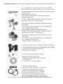
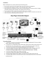
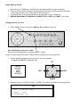
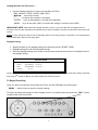
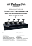
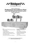
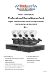
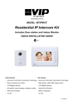
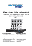
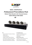
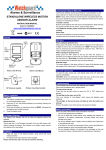
www.watchguardalarms.com.au
MODEL: DVR4ENTPACK
Professional Surveillance Pack
Digital Video Recorder with 4 Security Cameras
‘QUICK INSTALLATION GUIDE’
N517
DVR
2 x Cameras –30m Infrared range for night operation
- Advanced MPEG4 Video Compression Technology
- High Quality CCD Image sensor
- Multiplex Operation
- 24 x IR LED’s
- Long Recording Duration
- 420 TVL Resolution, 520 x 582 Pixels
- Intelligent Video Motion Detection Recording
- Remote Network Surveillance & Backup Functions
- Easy to operate like a VCR
- System Auto recovery after power loss (blackout)
2 x Cameras –15m Infrared range for night operation
- High Quality CCD Image sensor
- 12 x IR LED’s
- 420 TVL Resolution, 520 x 582 Pixels
Package Contents (Before commencing installation, please ensure you have all the parts listed below.)
Monitor
* Note: If you wish to connect directly from the DVR to a PC you require a crossover cable (Not Included)
1
Installation
Before installing this unit, please read through the following points:
• Do not place cords from the AC adapter where they can be pinched or stepped on.
• Do not place heavy objects on cords, or cover cords with rugs or carpet.
• Never immerse any component in water, and do not spray cleaners of solvents on the unit. Unplug
units before cleaning. When cleaning, use a damp, lint-free cloth only.
• Do not expose the DVR or Camera’s to excessive heat, cold, or moisture
• Leave at least a 2” space between the DVR and other objects to allow air circulation around the unit.
• Service should be handled by qualified technicians.
3
7
5
8
1
2
Impedance
matching not
required with
this camera
package
Not used with
this camera
package
WARNING
4
Please ensure you use
the correct power
supply for each
component.
DO NOT plug the 19V
DVR Power supply into
the cameras as this will
damage them.
Optional – Input/Output sensing
Not used with this package
6
Connection Guide
1.
2.
3.
4.
5.
6.
7.
8.
9.
Locate the 4 Cameras as required and connect the supplied combination DC Power and Video
leads. (Yellow to Yellow / Red to Red)
Connect the 4 x corresponding camera Video leads (Yellow) into the camera inputs at the rear of
the DVR (Take note of the Camera input 1 – 4, as this will determine the camera channels)
Connect the 4 x camera DC Power leads (RED) into the Power Split Cable
Connect the Monitor Connection Cable into the BNC Monitor output on the rear of the DVR.
Connect the Monitor Connection Cable into the RCA Video input on your TV/Monitor
(TV/Monitor Not Supplied) Note: (Requires composite video input monitor - not VGA)
Connect the 2Amp 19VDC Power adaptor to the DVR
Connect the 12VDC Power adaptor to the Power Split Cable.
Plug both Power adaptors into a 240Volt / AC Power Point and switch power point ON
The Power LED at the front of the DVR should now be illuminated Red and the unit will make a
loud beep sound.
2
Quick Start up Guide
•
•
•
•
Make sure your TV/Monitor is ON and set to the appropriate AV channel if required
Press the Power button located on the front panel of the DVR, the LED will illuminate Green
it takes approximately 10 to 15 seconds to boot the system.
The images from all 4 cameras should now be displayed on your TV/Monitor
BEFORE BEGINNING TO RECORD YOU MUST SET the DATE and TIME on your DVR.
Setting the Date and Time
•
Press “MENU” button to enter the (OSD) On Screen Display menu list.
The default admin password is 0000.
Enter the default password by pressing “ENTER” 4 times.
(Users can alter the password later. Please refer to the Advanced set up guide CD)
•
Use the following buttons to move the cursor for menu settings:
“UP=▲,DOWN=▼,LEFT=◄,RIGHT=► “
UP
(MENU)
RECORD
TIMER
DATE
ADVANCE
RIGHT
LEFT
DOWN
•
Move the cursor to “DATE” and press, ”ENTER”. The screen will show the following options
DATE
DATE
FORMAT
12 - MAY - 2006
16:30:00
D-M-Y
DAYLIGHT SAVING
ON
3
Setting the Date and Time Cont…..
•
Use the following buttons to set the correct Date and Time
(DAY / MONTH / YEAR / HOUR / MIN / SEC)
“▲▼◄► “ to move the cursor.
“+”, “-” to choose the numbers / selections.
“ ENTER “ to go to the submenu / to confirm the selection
“ MENU “ to go to the menu OSD / to confirm the change / to exit the menu OSD
IMPORTANT NOTE: Please DO NOT change the date or time on your DVR after the recording function is
activated. The recorded data will be disordered and you will not be able to find the recorded file to backup by time
search.
NOTE: If users change the date or time accidentally when the recording function is activated, it’s recommended to
clear all HDD data, and start recording again.
Daylight Saving
•
•
•
Specify whether to use daylight saving time and time period. (START / END)
Daylight saving time can be adjusted manually.
Enter the daylight saving menu mode to set the start time and the end time, and adjust hours of
the daylight saving.
DAYLIGHT SAVING
START
4TH-SUN-OCT
01: 00: 00
END
4TH-SUN-MAR
01: 00: 00
ADJUST
01 : 00
NOTE: The illustrated setting means: During the daylight saving time period (start from the 4th Sunday of October,
end on the 4th Sunday of March), the DVR system time will add one hour.
To Begin Recording
Once you have successfully set the Date and Time, exit the OSD Menu by pressing the
“ MENU “ button until you return to normal viewing.
To begin recording check that you have images from all 4 x cameras and then press the “ REC “ button
located at the front of the DVR.
4
To Stop Recording
In the event you wish to stop recording press the “ MENU “ button located at the front of the DVR.
•
Move the cursor to “RECORD” and press, ”ENTER”.
(MENU)
RECORD
TIMER
DATE
ADVANCE
•
The screen will show the following
RECORD
•
•
MANUAL RECORD ENABLE
YES
EVENT RECORD ENABLE
NO
TIMER RECORD ENABLE
NO
OVERWRITE
YES
RECORD IMG SIZE
CIF
RECORD QUALITY
BEST
MANUAL RECORD IPS
012
EVENT RECORD IPS
012
TIMER RECORD IPS
012
TOTAL IPS SHARE
FIX
Select “MANUAL RECORD ENABLE” and press “ENTER”
The screen will now show the following
WARNING
STOP RECORD
ARE YOU SURE ?
YES
•
•
NO
Move the cursor to “YES” and press “ENTER”
The DVR will now stop recording until the REC button is pressed again
5
Recording Options:
Recording Times
•
This DVR is factory set to record “CIF Best Quality” at 3 frames per second, per camera, at a
resolution of 352 x 288 pixels. This will provide approximately 4 weeks of recording time on this
setting. Using Video Motion Detection or reducing image quality can achieve much longer record
times if required.
This unit can be set up to record up to a maximum of 6.25 frames per second per camera in
“Frame Mode, 720 x 576 pixels, High Resolution” (MJPEG Compressoin) or 25 frames per
second per camera in “CIF Mode (Real Time),(MPEG4 Compression) 352 x 288 pixels”
(To alter the recording method please refer to the Advanced set up guide CD)
•
Recording Modes
The DVR offers three recording modes, MANUAL RECORD, EVENT RECORD and TIMER RECORD.
**
This unit is set to “Manual Record” by the factory.
( Please refer to the Advanced set up guide CD for details on how to change the recording mode)
MANUAL RECORDING (continuous recording) :
Recording is initiated by manually pressing the “REC” button, indicated by the sign “
” on the screen.
EVENT RECORDING (triggered by motion and external alarm) :
When this function is activated, the recording is triggered by motion or external alarms, indicated by the
sign "
" (motion) or "
" (external alarm) on the screen.
TIMER RECORDING (scheduled time) :
Recording is scheduled by Timer, indicated by the sign “TIMER RECORD”.
IMPORTANT NOTE : If power is switched off accidentally or in the case of a black out, recorded video files will
still be still stored in the HDD. The DVR will return to the original recording status after power is turned on again.
Typical Viewing Screen
The image below shows a typical screen shot from an installation
System Time
Remaining Available
Capacity of Internal HDD
2006-MAY-12 [FRI] 16:18:43
** Overwriting View
78.5 GB
** Under HDD
-OW-
Overwriting Mode
●
●
Under Recording
When the HDD is full under “-OW-”
recording mode, the previous
recorded data may be overwritten
without further warning notice. Your
DVR will clear 8GB from the oldest
data for overwriting.
Channel Title
Unit is pre-set by factory with
Overwriting View Switched to on.
6
●
●
To Play Back Captured Video Footage
Press “
” / “PLAY” button and the DVR will display the last recorded video.
FAST FORWARD (F.F. ) & FAST REWIND (REW):
You can increase the speed for fast forward and rewind on the DVR in the playback mode,
•
Press “►►“ once to get 4X speed forward and press twice to get 8X speed, etc., and the
maximum speed is 32X.
• Press “◄◄“ once to get 4X speed rewind and press twice to get 8X speed, etc., and the
maximum speed is 32X.
SLOW PLAYBACK:
• Press “SLOW” button to get 1/2X speed playback.
PAUSE / IMAGE JOG:
• Press “ II “ button to pause the current image displayed on the screen.
In the Pause mode
• Press “►► “ once to get one frame forward
• Press “◄◄ “ once to get one frame rewind
CHANNEL SHIFT:
Display mode:
• Press MODE “
” button to 4 channels display.
Full Screen Switch:
• Press “1 ” “2 ” “3 ” “4 ” buttons to show the full screen channels.
STOP:
• Pressing “ ■ “ button under all circumstances will return DVR to live monitoring mode
The image below shows a typical Play-Back screen shot from an installation
2006-MAY-12 [FRI] 16:18:43
78.5 GB
-OW-
The type of
Play-Back
Time
(Time Of
recording
●
●
image size
(Frame or
Actual
CIF)
Event)
2006-MAY-12 [FRI] 15:12:32
FRAME PLAY
●
●
7
Searching for data using Date and Time
You can also use the search function of the DVR to look back though stored data via date and time
•
Press “SEARCH” button on the front panel of the DVR to enter the search mode.
•
Then the screen will show the following options.
SEARCH
HDD-MASTER-1
FULL LIST
RECORD LIST
SYSTEM LIST
ALARM LIST
MOTION LIST
EVENT SEARCH
TIME SEARCH
•
•
Select “TIME SEARCH” from the menu,
Enter the Date and Time (DAY / MONTH / YEAR / HOUR / MIN / SEC) of the event you wish to
view using the following buttons:
“▲▼◄► “ to move the cursor.
“+”, “-” to choose the numbers / selections.
“ ENTER “ to go to the submenu / to confirm the selection
“ MENU “ to go to the menu OSD / to confirm the change / to exit the menu OSD
•
•
•
Once you have entered the Date and Time move the cursor to the SELECT button and press
“ENTER”
The DVR will then start playing back recorded data from the selected period, use the FAST
FORWARD / REWIND / PAUSE / SLOW PLAYBACK and CHANNEL SHIFT buttons on the unit
to navigate through the footage as required
To finish viewing the playback, press the stop “ ■ ” button to return to the live display
8
2
Operation
12
“LED LIGHTS”
1
“MENU”
2
“ENTER” / “SET”
3
3
4
11
5
6
7
8
9
1
10
HDD: HDD is reading or recording
HDD Full: HDD is full.
ALARM: Once the alarm is triggered
TIMER: When timer recording is turned on
PLAY: Under playing status
REC: Under recording status
Press “MENU” button to enter the main menu.
Press “ENTER” button to confirm the setting.
Press “SET” to change the position of the channel display.
Press “▲▼◄►“ to select the channel which you would like to change.
Press “+” or “-” to select the channel which You would like to show.
Press “REC” button to activate the manual recording.
4
“REC”
5
“SEARCH”
6
“SLOW”
Under the playback mode, press “SLOW“ button to show slow playback.
7
“ZOOM”
Press “ZOOM” button to enlarge the picture of selected channel (under the live
mode).
Press “SEARCH” button to enter the search menu.
Press “
“
8
“SEQ” / “ + ”
9
10
11
”/“ - ”
“
“ or “Power”
“CH1 ” “CH2 ” “CH3 ” “CH4 ”
“
” or “PLAY”
12
UP / PAUSE
DOWN / STOP
LEFT / REWIND
RIGHT / FAST FORWARD
OPT
SLOW & ZOOM
OPT
& SEQ
“ button to show the 4 channel display mode.
Press “ - ” button to change the setting in the menu.
Press “SEQ” button to activate the call monitor function and press “SEQ” button
again to escape the call monitor mode.
Press “+ ” button to change the setting in the menu.
Press this button to turn (On / Off) the DVR.
(Under the recording mode, please stop recording before turning off the DVR).
Press “1 ” “2 ” “3 ” “4 ” buttons to select the channel to display
Press “
“ to playback the recorded data.
Press “▲▼◄►“ to move the cursor up / down / left / right.
Under the playback mode, press “ II “ button to pause playback.
Under the playback mode, press “ ■ “ button to stop playback.
Under the playback mode, press “►►“ button to fast forward.
Under the playback mode, press “◄◄“ button to fast rewind.
Press these two buttons to select live or playback sounds of the audio channels.
Press these two buttons at the same time to enter / exit the PTZ control mode.
9
TROUBLE SHOOTING
Please refer to the FAQ table below for easy troubleshooting. The table below describes some
typical problems and also their solutions. Please check here and further FAQ on the included
user manual CD before calling your DVR dealer.
PROBLEM
SOLUTION
No power
Check power cord connection.
Confirm that there is power from the outlet.
Press any key and then enter the password to
exit “Key Lock” mode.
Check if the “TIMER RECORD ENABLE” is set
to “YES”.
Check the camera’s video cable and
connections.
Check the monitor’s video cable and
connections.
Confirm the camera is power supplied.
Check the setting of the camera lens.
Check if the HDD is installed and connected
properly.
Make sure the power connector and HDD are
connected closely, or change another suitable
HDD.
Change another HDD for testing.
Change another HDD cable for testing.
Make sure HDD “Master”, “Slave” mode is
correctly set.
Change another USB flash drive to test.
Update the JAVA program
Update the firmware of the software AP
There must be at least 8192 images of recorded
data for playback to work properly. If not, your
DVR will stop the playback.
For example, if the IPS is set to 30, the recording
time should be at least 273 seconds (8192
images / 30 IPS) for the playback to work
properly.
Not working when pressing any button
Timer record is not working
No live video
No recorded video
DVR keeps rebooting
HDD detection failed
Can’t detect your USB flash drive
Can’t view the DVR images over the network with
IE web browser
Can’t play the recorded data on my DVR
This guide is intended as a Quick Set Up and Basic use manual only, please refer to the
user manual on the included CD for all other details.
10
Limited Warranty
Cornick Pty Ltd (Seller) warrants its products to be in conformance with its own plans and specifications and to be free from
defects in materials and workmanship under normal use and service for twelve months from the date of original purchase.
Sellers obligation shall be limited to repairing or replacing, at its option, free of charge for materials or labor, any part which is
proved not in compliance with Sellers specifications or proves defective in materials or workmanship under normal use and
service. Seller shall have no obligation under this Limited Warranty or otherwise if the product is altered or improperly repaired
or serviced by anyone other than Seller.
For Warranty Service: Return transportation prepaid with a copy of your purchase receipt and contact details to:
RhinoCo Technology, 9 Hannabus Place, McGraths Hill, NSW 2756 Australia.
Seller has no obligation to attend the buyer’s location to retrieve the goods or make repairs onsite.
•
There are no warranties, expressed or implied, of merchant ability, or fitness for a particular purpose or otherwise, which
extend beyond the description on the face hereof. In no case shall seller be liable to anyone for any consequential or
incidental damages for breach of this or any other warranty, express or implied, or upon any other basis of liability
whatsoever, even the loss or damage is caused by its own negligence or fault.
•
Seller does not represent that the products it sells may not be compromised or circumvented; that the products will prevent
any personal injury or property loss by burglary, robbery, fire or otherwise; or that the products will in all cases provide
adequate warning or protection. Customer understands that a properly installed and maintained alarm system or video
surveillance system may only reduce the risk of a burglary, robbery, or fire without warning, but it is not insurance or a
guarantee that such will not occur or that there will be no personal injury or property loss as a result.
•
Consequently, seller shall have no liability for any personal injury; property damage or other loss based on a claim the
product failed to give any warning. However, if seller is held liable, whether directly or indirectly, for any loss or damage
arising under this limited warranty or otherwise, regard less of cause or origin, seller's maximum liability shall not in any
case exceed the purchase price of the product, which shall be the complete and exclusive remedy against seller.
•
This warranty replaces any previous warranties and is the only warranty made by the Seller on this product. No increase or
alteration, written or verbal, of the obligations of this Limited Warranty is authorised.
Please refer to the website (www.watchguardalarms.com.au) for a full list of trading terms.
HELPDESK: Phone 02 4577 4708
9am – 5pm Mon- Fri
11
PLEASE CUT OUT & RETURN THIS INFORMATION
WITHIN 14 DAYS OF PURCHASE TO:
RhinoCo Technology
9 Hannabus Place
McGraths Hill NSW 2756 Australia
M o d e l : D V R 4 E N T PA C K
P r o f e s s i o n a l S u r v e i l l a n c e P a c k Wa r r a n t y C a r d
Name
Address
Suburb
State
Postcode
Email
Date of Purchase
Invoice Number
Daytime Phone
Where did you purchase your DVR4ENTPACK?
Store Location
This information will only be used by the manufacturer and will not be sold to any third parties.
Dear Customer,
We appreciate your confidence in our product, and you can be certain that we will do everything possible to ensure
that you are happy with your decision and that you have years of satisfaction from your DVR4ENTPACK.
We take extreme care in the research, design and development of our products to ensure they meet your needs.
Additionally, we keep in close contact with our dealers Australia wide, and should any problem occur, we will work
closely with your local dealer to see that it is resolved quickly.
As a leading designer and manufacturer, we are continually endeavouring to exceed the expectations of our
customers. Furthermore, we appreciate your input regarding potential design improvements, issues regarding our
service and support, and any other ideas you may have which could help us to serve you better.
Please make any comments you have here:
12