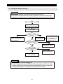
1
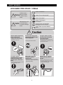
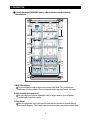
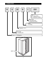
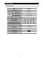
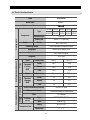
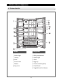
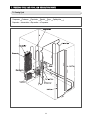
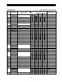
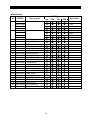
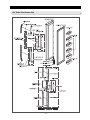
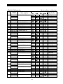
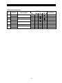
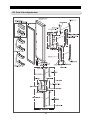
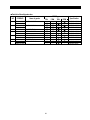
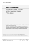
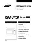
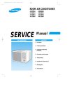
SAMSUNG Home Appliance Service
For the latest parts information,
please access to our service web site
(http://www.e4buyer.com/refrigerator)
SIDE-BY-SIDE REFRIGERATOR
Model:
RS20NCSL
RS20NCSW
RS20NESL
RS20NESW
WARNING
IMPORTANT SAFETY NOTICE
The service guide is for service men with adequate backgrounds of
electrical, electronic, and mechanical experience. Any attempt to repair
a major appliance may result in personal injury and property damage.
The manufacturer or dealer cannot be responsible for the interpretation
of this information.
SAMSUNG ELECTRONICS
Technical Service Guide
Copyright ⓒ2002
All rights reserved. This service guide may not be reproduced in whole or in
part in any form without written permission from the SAMSUNG ELECTRONICS
Company.
2
Contents
1. SAFETY WARNINGS
4
2. INSTRUCTION
6
3. INSTALLATION
7
4. NOMENCLATURE
8
5. SPECIFICATIONS
9
6. INTERIOR VIEWS AND DIMENSIONS
12
7. FREEZING CYCLE AND COOL AIR CIRCULATION ROUTE
14
8. MECHANICAL DISASSEMBLY
16
9. FUNCTIONS AND OPERATION
22
10. CIRCUIT DESCRIPTION
27
11. DIAGNOSIS AND TROUBLESHOOTING
36
12. ILLUSTRATED PARTS CATALOGUE
42
APPENDIX Ⅰ (CIRCUIT DIAGRAM)
57
3
1. SAFETY WARNINGS
● Pull the power plug out already for the change or repair of electric parts.
→ Be careful the electric shock.
● When exchanging the parts, use the correct parts.
→ Check the model name, rating voltage, rating current, running
temperature symbols.
● When troubleshooting, connect firmly the types of harness.
→ Make not to be separated when some power is imposed.
● Check the traces of water infiltration at the electric parts.
→ If there is a trace of water infiltration, exchange or tape the parts.
● Check the assemble status of parts after troubleshooting.
→ It should be done indiscriminately as before the repair.
● Check the use circumstance of refrigerator.
→ If the refrigerator is installed at the place that is damp or wet, or
status of installation is unstable, change the installation place.
● Do earth in case of need.
→ Particularly, Be sure to earth when there is a risk of an electric
leakage by humidity or wetness.
● Do not use multi plugs in a plug socket at the same time.
Check the power cord and socket is damaged, pressed, squeezed, or
fired.
→ If the plug or plug socket is damaged, repair or exchange that
immediately.
● Do not store the foods unstable or bottles in the freezing room.
● Do not repair the refrigerator by user himself.
● Do not store another materials except the foods.
→ Drugs or scientific materials : difficult to keep a precise temperature.
→ The inflammables(alcohol, benzene, ether, LP gas, butane gas etc.):
have a risk of explosion.
4
1. SAFETY WARNINGS
CAUTION / WARNING SYMBOLS DISPLAYED SYMBOLS
Warning
Caution
means “Prohibition”.
Indicates that a
danger of death
or serious injury
exists.
means “Do not disassemble”.
means “No contact”.
means ”The things to
be followed”.
Indicates that a risk
of personal injury
or material damage
exists.
means “Power cord should be
unplugged from the consent”
means “Earth to prevent Electric
shock”.
Caution
Use the rated components
on the replacement.
●Check the correct model, rated
voltage, rated current, operating
temperature and so on.
On repair, remove
completely dust or other
things of housing parts,
harness parts, and check
parts.
●Cleaning may prevent the possible
fire by tracking or short.
Pull the power plug out to
exchange the interior lamp
of the refrigerator.
On repair, make sure that
the wires such as harness
are bundled tightly.
● It may cause electric shock.
●Bundle tightly wires in order not to
be detached by the external force and
then not to be wetted.
After repair, check the
assembled state of
components.
Check if there is any trace
indicating the permeation
of water.
●It must be in the same assembled
state when compared with the state
before disassembly.
5
●If there is that kind of trace, change
the related components or do the
necessary treatment such as taping
using the insulating tape.
2. INSTRUCTION
A newly developed SAMSUNG side by side refrigerator has the following
characteristics.
1) Multi-Flow System
Cool air circulates through multiple vents on each shelf level. This provides even
distribution of cooling inside of freezer/refrigerator and keeps food fresher for longer.
2) High humidity for fresher food
You can keep food, fruit and vegetables fresh for longer because your refrigerator
supplies highly humidified cold air.
3) Door Alarm
When the refrigerator door is left open for more than two minutes, a musical alarm is
automatically triggered. This feature helps you save electricity and preserve stored foods.
6
3. INSTALLATION
1) To protect refrigerator in movement
Use padded hand truck as shown. If entrance width is
less than 30 , remove doors prior to installation and
reattach doors according to procedure below.
2) Remove all protective tape and pad in refrigerators.
Please adjust the clearance between the doors.
3) Set the temperature control to the temperature and
wait for an hour.
The refrigerator should get slightly chilled and the motor
runs smoothly.
4) Once the refrigerator temperature is sufficiently cool
You can store food in the refrigerator. After starting the
refrigerator, it takes a few hours to reach the appropriate
temperature.
Disassemble the refrigerator
1)
2)
1) With the door closed, disassemble screw( ) by
using (+) screw driver and then disassemble the
upper hinge cover( ).
2) Disassemble bolts ( ) and screws ( ) to the
counter-clockwise by using a tool, and take off the
upper hinge ( ) along the arrow ( ). Take care
when you disassemble the door to ensure that it does
not fall on you.
3)
Assemble the refrigerator
1)
2)
1) Insert the lower hinge ( ) in the bracket lower
hinge ( ).
2) Assemble the door ( ) in the lower hinge ( ).
3)
4)
4)
3) Disassemble the door from the lower hinge ( ) by
lifting the door ( ).
4) Disassemble the lower hinge ( ) from the bracket
lower hinge ( ) by lifting the lower hinge ( ) in the
direction of the arrow.
3) Insert the upper hinge shaft ( ) into the hole ( ). After
leveling between the upper hinge hole ( ) and the
hole of the refrigerator ( ), assemble bolts ( )
and screws ( ) to the clockwise by using a tool.
4) Put the front part of the upper hinge cover ( ) on the
front part of the upper hinge ( ) and assemble,
starting with the front part of the upper hinge
cover. Assemble the screw to the clock wise by
using a tool.
7
4. NOMENCLATURE
R
S
20
N
C
SW
Color
SW : Snow White
SL : Stainless Looking
Handle Type
C ; Sky Bar Handle
E ; Deluxe Bar Handle
Option
N : Nothing
Capacity ; Cu. ft
Door Type
S - Side By Side
Product ; R - Refrigerator
Label Location
8
5. SPECIFICATIONS
5-1. Model Specification
Volume
capacity
Items
Specification
Model Name
RS20N***
Total Volume
496 l(17.5 cu.ft)
Freezer Volume
188 l(6.6 cu.ft)
Refrigerator Volume
308 l(10.9 cu.ft)
Outer dimensions(width x depth x height)
850mm×724mm×1722mm
Rated frequency Hz
60
60
50
50/60
50
Rated voltage V
110 115
127
220
220
230
Rated consumption of Comp. W
140
125
120
140
125
Rated consumption of Electric heater W
394
Refrigerator type
Frost free
Refrigerant
HFC - 134a
Refrigerant quantity
190gr
Freezing Capacity
Products weight
106kg
9
5-2. Electric Parts Specification
Items
Specification
Model Name
RS20N***
Performance of freezer
Type
110V/60Hz 127V/60Hz 220V/50Hz 220V/50,60Hz 230V/50Hz
MK183CL2U/EH1 MK183PL2U/EO1 DK190KT2U/EO1 SK190HL2U/E01 MK183QL2U/EO1
Freezing parts
Compressor
Freezer
Refrigerator
Defrostperiod
Defrost
sensor
Inner Temperature detection parts
R.S.C.R
Sealing oils
FREOL α- 15 (ESTER)
Freezer
SPLIT FIN TYPE
Cooler
Condensing method
Force and natural convection method
Drying agent
MOLECULAR SIEVE XH-9
Capillary tube
0.82×3200, 5.5 kg/cm2
Refrigerant
HFC-134a
Types
Parts related defrost
Operation type
Freezer temp.
ON(℃)
OFF(℃)
Thermistor
(F-sensor)
502AT
Colder
-24.0
-26.0
Normal
-19.0
-21.0
Cold
-15.0
-17.0
Types
Refrigerator temp.
ON(℃)
OFF(℃)
Colder
2.0
0.0
Normal
4.0
2.0
Cold
7.0
5.0
Thermistor
(R-sensor)
502AT
Period of initial defrost (F defrost)
4 hours ± 10 mins
Defrost period of freezer
6~11 hours(Variable according to the use conditions)defrost
Pause
7 ± 2 minutes
F-defrost
sensor
Temperature fuse
Types
THERMISTOR (PX41C)
Spec
5.0㏀ at 25
Rating
AC 250V 10A
77
Operation temp.
10
+0
-5
℃
Specification
Items
F-room defrost heater
Conducting at F defrosting
200W
F room heater sub
Conducting at F defrosting
60W
F room heater glass
Conducting at F defrosting
130W
R-room cover damper
3W
R room electrically driven damper
1W
Running
Condenser for
Comp.(monolithic)
Start
Electricparts
-
-
-
-
-
Type
J531Q32E4R7M1802 J531Q32E4R7M1802 J531Q34E220M3502 J531Q34E220M3502 J531Q35E330M3852
Action
Initial resistance: 68Ω±20% (Ambient temperature : 25℃)
Type
4TM437RHBYY-53 4TM437RHBYY-53 4TM317SHBYY-53 4TM317SHBYY-53 4TM265RHBYY-53
ON temperature
130 ± 5℃
OFF temperature
69 ± 9℃
Start relay
Overload relay
250VAC,12㎌ 250VAC,12㎌ 350VAC,5㎌ 350VAC,5㎌ 350VAC,5㎌
L.V.T(LOW VOLTAGE TRANSFORMER)
110 115V/60Hz 127V/60Hz
220V/50Hz
230 240V/50Hz
F room cooling fan motor
DC 12V DREP3030LA 0.3A
Comp. Cooling fan motor
DC 12V DRCP3030LA 0.24A
Freezer interior light
30W (110 127V)
25W (220 230V)
Refrigerator interior light
30W (110 127V)
25W (220 230V)
Door switch
AC 250V 0.5A 2EA
Supply cord
TO BE FOLLOWED LOCAL STANDARD
Grounding screw
BSBN (Bronze screw)×4EA
11
6. INTERIOR VIEWS AND DIMENSIONS
6-1. The Name of Each Part
Freezer
Refrigerator
① Interior light
⑦ Dairy compartment
② Ice tray
⑧ Interior light
③ Shelf
⑨ Shelf
④ Food Guard
⑩ Egg tray
⑤ Drawer
⑪ Fresh container(option)
⑥ Leg cover
⑫ Food Guard
⑬ Vegetable and fruit drawer
12
6-2. Dimensions of Unit
13
7. FREEZING CYCLE AND COOL AIR CIRCULATION ROUTE
7-1. Freezing Cycle
Compressor Condenser
Evaporator Accumulator
Pipe cluster
Pipe suction
Pipe hot Dryer
Compressor
14
Capillary tube
7-2. Cooling Air Circulation
Refrigerator
Freezer
15
8. MECHANICAL DISASSEMBLY
8-1. Accessories for storage and parts for lightening
Door Gasket
SHELVES
The door gasket is set into groove on door liner.
1) Open the door.
2) Grasp the gasket and pull it out from
the door liner.
1) Pull the shelf out as far as it goes.
2) Lift it up and pull it out from the unit.
ICE TRAYS
The ice tray is located at bottom of freezer shelfmid.
1) Pull the tray out by sliding.
LIGHT SWITCHES
The unit have two light switches on the side wall
of freezer & refrigerator.
1) Use a small flat-blade screw driver to unlock
the hook and pull the switch out until the wire
connector is exposed.
DRAWERS
The drawers are located at bottom side of freezer
and refrigerator.
1) Pull the drawer out as far as it goes.
2) Lift it up slightly and pull it out from the unit.
LIGHTS
The light of freezer & refrigerator are located at
upper side of each compartment.
1) Remove the screws.
2) Remove the lamp cover by unlocking the
hook.
16
TRAY-REF
SHELF LOW REF. IN REFIGERATOR
The tray-ref is located at bottom of shelf-ref
in refrigerator compartment.
1) Pull the tray-ref out as far as it goes.
2) Lift it up slightly and pull it out from the shelf.
The shelf low ref. in refrigerator can be
removed as following sequence.
1) First, remove the drawer upp..
2) Pull the shelf out as far as it goes.
3) Lift it up and pull it out from the unit.
FOOD GUARDS
1) Lift the guard up and pull it out from door liner.
17
8-2. Cooling Unit
COVER EVAP FRONT IN FREEZER
COVER DUCT REAR IN FREEZER
Before disassemble the cover, Should be
removed all accessories in freezer.
1) Pull the screw cap out (4 EA).
2) Remove the screws (6 EA).
3) Grasp the bottom edge of the cover, and pull it
out from the unit.
Before disassemble the cover, Should be
removed cover duct. front.
1) Remove the screws (3 EA).
2) Grasp the bottom edge of the cover, and pull it
out from the unit.
3) Disconnect the wire connector and pull the
cover out from the unt.
COVER DUCT FRONT IN FREEZER
Before disassemble the cover, should be cover
evap. front.
1) Pull the screw cap out (1 EA).
2) Remove the screws (1 EA).
3) Grasp the bottom edge of the cover, and pull it
out from the unit.
4) Disconnect the sensor wire connector
and pull the cover out from the unt.
FAN MOTOR
1) Remove the fan propeller (1 EA).
2) Disconnect the wire connector from body of
the cover.
3) Remove the screws (3 EA) and separate the
fan motor case.
4) Open the case and remove fan motor.
18
2) Cut the cable tie for securing the thermistor.
3) Separate the thermistor from the evaporator.
Do not desolder evaporator to replace the
thermistor only.
EVAPORATOR IN FREEZER
1) Take off cover evap front, cover duct front
and cover duct rear in sequence.
2) Disconnect all wire connectors.
3) Desolder the inlet and outlet tube.
4) Remove the evaporator.
THERMISTOR IN FREEZER
Before disassemble the thermistor, Should be
removed cover duct. front.
1) Remove the sensor cover.
2) Separate thermistor.
Thermistor-defrost
Thermal
Fuse
Sensor
AMBIENT THERMISTOR
The thermistor is located at inside the upper
hinge cover. It sends temperature signal to the
micro-processor.
THERMAL FUSE
Thermal fuse is located at top of the evaporator.
1) Disconnect the wire connector of thermal fuse.
2) Cut the cable tie for securing the fuse.
3) Separate the fuse from the evaporator.
Do not desolder evaporator to replace
the fuse only.
THERMISTOR DEFROST
Thermal fuse is located on accumulator of
evaporator.
1) Disconnect the wire connector of thermistordefrost.
19
ASS'Y DAMPER
The Damper is for controlling cold air circulation.
●After disassemble cap screw(①) disassemble the screw(② ).
●Disassemble the connectors then, pull out the damper cover(③ ) from refrigerator.
●After disassembling the screw(④) from the damper cover(③), disassemble the temperature
control part by pulling forward from the damper cover(③).
●Disassemble the screw(⑤) from the assembly part of temperature control part. And disassemble
the PBA board.
●Assembly is reverse of disassembly.
COVER MULTI IN REFRIGERATOR
THERMISTOR IN REFIGERATOR
Before disassemble the thermistor, Should be
removed cover multi.
1) Peel off the tape on the back side cover
assembly.
2) Separate insulation of cover multi from the
cover.
3) Remove the sensor.
Before disassemble the cover, Should be
removed Ass'y damper.
1) Pull the screw cap out (1 EA).
2) Remove the screws (1 EA).
3) Disconnect the wire connector of thermistor.
4) Grasp the bottom edge of the cover,
pull it down and remove it.
20
8-3. Machine compartment
Condenser Fan
Machine Compartment & Electric Box
The condenser fan is located in the middle of
machine compartment it cools down the subcondenser and compressor.
1) Disconnect the wire connector of Fan.
2) Remove the screws (1 EA) on the drain water
tray.
3)Take out the condenser fan assembly.
1) Disconnect the compressor cover by releasing
the screws(6EA).
2) Remove the screws which are securing the
electric box. and press the tap in electric box
coverto take outbyusing a flat-blade screw
driver.
Sub-condenser
The sub-condenser is located in the machine
compartment.
1) Desolder the compressor discharge & the
outlet of sub-condensor.
2) Take out the sub condenser.
(+)driver
(-)driver
Desoldering Point
PCB-MAIN ASSY
21
9. FUNCTION AND OPERATION
9-1. Panel Display
REF. TEMP. BUTTON
To set the refrigerator temperature,
push the button repeatedly to select a
level between 1 level (cold) to 9 level
(colder).
FRE. TEMP. BUTTON
To set the freezer temperature, push the
button repeatedly to select a level between
1 level (cold) to 9 level (colder).
• The higher level you set, the lower temperature inside the unit.
NOTE
9-2. Temperature Control
1) Freezer
• The freezer temperature can be set to a level
between 1 level (cold) to 9 level (colder).
• Push the FRE. TEMP. button repeatedly until the
desired level is reached.
- At each level, the LED lamps will turn on or off as
shown on the table.
Control table
Temp. Fre -16℃ -18℃
(about) Ref 6℃ 4℃
Reference
LED ⑤
condition ④
(on)
③
(off)
②
◐(blink)
●
○
2) Refrigerator
• The refrigerator temperature can be set to a level
between 1 level (cold) to 9 level (colder).
• Push the REF. TEMP. button repeatedly until the
desired level is reached.
- At each level, the LED lamps will turn on or off as
shown on the table.
NOTE
cold
●
level
⑤
④
③
②
◐
1 2
-20℃
3℃
-22℃
2℃
-25℃
1℃
normal
colder
●
④ ④ ④ ④ ● ◐ ●
③ ③ ● ◐ ● ● ●
● ◐ ●●●●●
●●●●●●●
⑤
⑤
⑤
⑤
⑤
⑤
3
4
5
6
7
8
9
After blinking (◐) for 3second, led turn on (●).
• For your convenience, your freezer/refrigerator controls have been preset at the factory. The
freezer/refrigerator control should both be set to normal (level 5) when you first install your
freezer/refrigdfator.
22
9-3. Alarm
”)
1) Button touch sound (“DING-DONG”
If the panel button is pressed, “DING-DONG” sound of input confirm is occurred.
If the buttons are pressed at the same time or incorrectly, this sound is not occurred.
2) Alarm sound at the door opened ( “beep” )
If the door of refrigerator/freezer is opened and has passed 2 minutes, the
alarm is occurred in 10 seconds.
If the door is remained in open continuously, the alarm continues for 10 seconds 1 minute periodic.
The alarm is sopped at once after closing the door of refrigerator/freezer.
3) Alarm sound at the forced start , defrost (“beep” )
If the forced start or defrost is selected , ( “beep” ) alarm sound occurred.
If the forced start is selected, the alarm is continued to the auto release(after 24 hours operation in
forced start) or the selection of release function.
Also at the forced defrost, the alarm is continued to the completion(including the pause times) or the
selection of release function.
9-4. Defrost
1) The freezer defrost is decided according to the integration time of Compressor ON.
2) At the initial power ON, freezer defrost is performed after 4 hours of integration time of Comp. ON.
3) After this, a defrost period is variable from 6 hours to 11 hours in accordance with the use condition and
ambient environment.
4) The defrost period is decided by the outdoor temperature, number and time of the opening of refrigerator
door.
9-5. Test function
1) Selection of test function
Following two procedures are sequences for changing normal mode into test mode.
Press both ‘R room key’ and ‘F room key’, and keeping pressing keys over 11 seconds.
Note) 0 3 seconds : no phenomenon
3 7 seconds : panel display blinks of 0.5 sec interval
7 11 seconds : panel display blinks of 0.2 sec interval
Press F room key after releasing two keys when 11 seconds passed. Then the mode is changed to the test
mode.
In the test mode, F room key is main key for changing status.
Note) One times : forced running
Two times : forced defrost (1)
Three times : forced defrost (2)
Four times : release function
23
2) The change of lamp displays test mode function(Pressing for 7 seconds)
At the time of test mode selection : Lamp all OFF
At the time of forced running selection : 8 lamps ON
At the time of forced defrost(1) selection : 5 lamps of
freezer control ON
At the time of forced defrost(2) selection : 5 lamps of
refrigerator control ON
At the release of test function : Lamp all OFF
3) Forced running
At the test mode, once more pressing the F room key selects forced running. At this time, buzzer performs alarm by
beep.
If the forced running is selected, compressor is in action immediately without 5 minutes delay action. If defrost is
proceeded at this time, defrost stops immediately.
If the forced running is selected, compressor and F-fan is operated on pull down for 24 hours, and R room is controlled
by set temperature.
The forced running is performed continuously until the completion(24 hours) or change to another mode, or release..
If the forced running is selected, freezer is selected to “ colder(-25 )” , and refrigerator “ middle colder(2 )”
After the forced running is completed(24 hours), defrost is performed regardless of the former mode.
If the forced running is released, Comp. on time during the forced running is reflected in a defrost period by addition.
24
4) Forced defrost
When the test mode is selected, if F room key is pressed in twice, the forced defrost(1) is selected.
If F room key is pressed in three times, the forced defrost(2) is selected. But the forced defrost(2) mode is not
used.
The beep sound continues, during the heating and resting period.
Damper (cooling air interception) closes until the completion of defrost time.
9-6. Self Diagnosis
1) Self diagnosis in the initial power on
When a power is ON, if internal MICOM will decide faulty in temperature within 1 second.
If faulty sensor is found, the “related display LED” switches ON and OFF for 0.5 second intervals.
At the LED situation is the faulty sensor display, self-test function key (F room key + R room key for
11seconds) is the control of normal temperature is delayed.
Fixing default sensor when there is an error, or press F room key and R room key for 11 seconds, it
automatically cancel self-test function and activate normally.
2) Self diagnostics in the normal operation
If “ F-ROOM +R-ROOM” key is pressed for 3 seconds at the normal operation, temperature setting display
proceeds ALL ON/OFF by 0.5 second intervals foe about 4 seconds. If “ F-ROOM +R-ROOM” key is pressed
for 7 seconds including 4 seconds of ON/OFF, all displays proceed ALL ON/OFF by 0.2 second intervals for
about 4 seconds. If “ F-ROOM +R-ROOM” key is pressed for total 11 seconds including 4 seconds of 0.2
second intervals ON/OFF, all displays becomes ALL ON and “ “ buzzer occurred, and then start a self
diagnosis.
Self diagnosis is performed from “ colder-colder” LED with being OFF in sequence at the state that freezer
/refrigerator temperature setting displays are all ON.
In case of detection inferior sensor, the corresponding display lamp keeps up ON.
(Self diagnosis display table)
No
Items
Symptorn
Troubles Remarks
Detaching the sensor Housing, fault of
Connection, open or short of power
cable, sensoritse lfinferiority, the others…
Detaching the sensor Housing, fault of
Outer
Connection, open or short of power
2
Sensor
cable, sensoritse lfinferiority, the others…
Detaching the sensor Housing, fault of
3 F-Sensor Connection, open or short of power
cable, sensoritse lfinferiority, the others…
F-room defroster Detaching the sensor Housing, fault of
Connection, open or short of power cable,
4
Sensor
sensoritse lfinferiority, the others…
Displayed inferiority When temperature
detection of sensor is over 65 ℃or below
-50℃.
Displayed inferiority When temperature
detection of sensor is over 65 ℃or below
-50℃.
Displayed inferiority When temperature
detection of sensor is over 65 ℃or below
-50℃.
Displayed inferiority When temperature
detection of sensor is over 65 ℃or below
-50℃.
Detaching of fan housing, fault of
In case that BLDC fan motor feed back
F Fan error
open or short of power
5 (only stopping) Connection,
cable,fan itself inferiority, constraint by signal is not detected ordetected the
abnormal signal.
fan wings freezing…
Detaching of fan housing, fault of In case that BLDC fan motor feed back
C Fan error
open or short of
6 (only stopping) Connection,
power cable, fan itself inferiority, signal is not detected ordetected the
constraint by fan wings freezing… abnormal signal.
1
R-Sensor
LED(cf. page23)
R “Cold.Mid”
R room LED No
F “Cold”
F room LED No
F “Cold.Mid”
F room LED No
F “Mid”
F room LED No
F “Mid. Colder”
F room LED No
F “Colder”
F room LED No
※ If you try to check the fan error condition, you should check the error at the forced running condition.
25
9-7. Display function of the presently operating parts
1) If you press ‘F room key’ and ‘R room key’ button together for 3 seconds during normal operation, LED
display will show ON/OFF for 4 seconds at interval of 0.5 second.
2) At this moment, if you take off ‘F room key’ and ‘R room key’ button and press ‘R room key’ button, it
change into the display of the presently operating parts.
3) This display condition is unrelated to actual operation and it is an reference of indication that MICOM
commanded operating order.
4) After 30 seconds illumination of error signal, the system will return to the normal operation.
(Display table of the presently operating parts)
NO
CONTENT
1
2
3
4
5
6
7
8
9
10
DAMPER
At the normal times
In the conditions of overload (over 30℃)
C-FAN HIGH
C-FAN LOW
COMP
F-FAN HIGH
F room defrost heater
F-FAN LOW
In the conditions of low temperature
DISPLAY LED
R “ Cold ”
R “ Cold. Middle ”
R “ Middle ”
R “ Middle. Colder ”
R “ Colder ”
F “ Cold ”
F “ Cold. Middle”
F “ Middle”
F “ Middle. Colder ”
F “ Colder ”
R room LED No
R room LED No
R room LED No
R room LED No
R room LED No
F room LED No
F room LED No
F room LED No
F room LED No
F room LED No
9-8. C-FAN(Comp-fan) Control In Accordance With Outdoor Temperature
1) According to the ambient temperature, the condenser fan located in the machine compartment is operated with
different modes.
Ranges of ambient temp.
C-FAN
Delay function
Operation
Above 18 ℃
C-FAN is ON as soon as the
compressor ON.
13 17 ℃
C-FAN is ON with 5 minutes delay from
the compressor ON.
Below 12 ℃
C-FAN is OFF regardless of the
compressor operation.
26
10. CIRCUIT DESCRIPTION
10-1. Power source part
Power source
Used circuit
Vcc(DC 5V) Surrounding power of MICOM and sensor detection part
+2V(DC 12V) Relay driving part, panel display part
BLDC(DC 12V) OP AMP, TR constant voltage circuit use(BLDC fan motor drive)
AC 220V input power is reduced by passing through LVT(DC-TRANS), this power is changed to DC voltage through
rectification diode. After this, DC 12V leveled by 1000uF/35V capacitor and settled by regulator 7812 is output and in use
for relay and panel PCB driving power, input power and refrigerator control.
Another the second of LVT(DC-trans) is leveled by rectification diode and 1000uF/35V capacitor, and controlled to set
voltage by OP amp, constant voltage TR circuit, and then supplies a settled voltage to BLDC motor.
10-2. Oscillation circuit part
Terminal
Oscillation frequency
Xin(#30)
4MHz
Xout(#31)
4MHz
Oscillation circuit is for clock occurrence for synchronism to the information transmission/reception of MICOM
internal elements and for time calculation. If the resonator spec is changed, normal function is not performed
because of the changing of MICOM timing system.
10-3. Reset circuit part
27
Terminal
Voltage
Vcc
DC 5V
RESET
DC 5V
Reset circuit is that initializes many internal parts of the MICOM and makes the all programs to act in the initial
state in case that power is impressed to MICOM by instantaneous interruption or power input. Reset terminal
voltage becomes to scores of us “ LOW” compared to the MICOM Vcc((DC 5V) voltage on power
impression, and keeps “ HIGH” (Vcc voltage) on the normal action.
10-4. Door S/W detection circuit
Terminal
Door state
MICOM input
CLOSE
0V (LOW)
OPEN
5V (HIGH)
CLOSE
0V (LOW)
OPEN
5V (HIGH)
F room
R room
CN30℃ is connected to GND and ② is supplied Vcc(DC 5V) by passing through Resistance R401
(10℃), and it detects F room door open/close by impressing to MICOM “ HIGH(5V)/LOW” . CN30 ℃ is
connected to GND and ① is supplied Vcc(DC 5V) by passing through resistance R403(10℃), and it
detects R room door open/close by impressing to MICOM “ HIGH(5V)/LOW” If there are some faults in
door S/W at this time, the corresponding fan is not act or alarm occurs. Check the door S/W whether it has
an abnormality. If the door is opened, the internal corresponding fan stops. This is occurred because
MICOM stops the fan deciding door open although door is closed when being S/W contact point
abnormality.
10-5. Temperature detection circuit
MICOM terminal
Voltage
Outdoor
temperature
PIN #57 (F-DEF-SENSOR)
MICOM terminal
voltage is
PIN #58 (R-SENSOR)
changed by the
PIN #59 (ATMOSPHERE SENSOR) temperature.
PIN #56 (F-SENSOR)
Sensor makes use of the character that resistance value becomes smaller when temperature is high, and bigger
temperature is low by use of thermistor having a indeterminate resistance temperature coefficient. R302,4,6,8 and
C301,2,3,5 have no concern with temperature detection because they are for noise
protection parts. In case of F-sensor, if the voltage that input to MICOM is supposed to Vf, Vf= (Rth x Vcc)/(R301
+ Rth).At this, Rth is a thermistor resistance value. Refer to attached appendix for MICOM terminal voltage
corresponded to temperature and resistance/voltage conversion table of sensor.
28
10-6. Key scan and display circuit part
1) Description of key scan and display drive action
As a following each part wave, “ HIGH” output is send out, by use of three terminals of MICOM No #5,6,7 by
6 msec intervals. This signal passes through input terminal of IC05 and is displayed to output terminal. At this
time, the peak to peak voltage of rectangle wave is about 12V, the shape of output wave is like following.
2) KEY SCAN
When GRID #3 wave is output, this signal is supplied to SW1 by passing through panel PCB R5 resistance
10℃. At this time, pressing SW1 makes a signal small by R508(6.8㏀) and R505(12㏀), and impress peak to
peak 4.5V to MICOM. MICOM decides that GRID #3 wave is input and changes the function corresponding
to SW1. Like this, each GRID wave is recognized.
29
10-7. BLDC MOTOR drive circuit
● Movement description
When F-fan is driven to LOW RPM, Resetting the MICOM #40 pin with being set #39 always links
the R705 and R707 in a parallel. At this time, the voltage is devided between a parallel resistance
value and R706, impressed to OP-AMP. It makes Q1 turn ON, F-fan drive. If F-fan is in condition
of OFF, MICOM #39 pin is reset and F-fan is stopped. In case of the Comp.-fan, it is controlled by
the same method with F-fan. But its drive voltage is different with that because there is a
difference in E1 voltage /E2 voltage due to the difference of RPM.
※ Fan motor protection
When the fan is not run because of F-fan/C-fan freezing or power cord connection part inferiority,
fan self-signal is not occurred. So MICOM decides fan abnormality. At this time, perform the fan
three seconds ON, seven seconds OFF in five times. If there is no signal during the fan ON/OFF
five times, after 10 minutes pausing repeat the three seconds ON, seven seconds OFF in
five times.
If the signal is occurred during the three seconds ON, seven seconds OFF, MICOM decides that
operation is normal and releases all motor protect functions and performs a normal function.
30
10-8. Load drive part circuit
● Movement description
When “ HIGH” signal is impressed to input terminal of IC04 at MICOM PIN NO #15, IC turns ON. At this time,
V12(DC 12V) connected to one side end of Comp relay passes through output of IC04 to ground, and the
core of relay causes a magnetic field and makes a contact point on. And AC input voltage(AC 220V) is
impressed to the both side end of Comp. load, Comp. acts. In case of the MICOM PIN #15 signal is “ LOW” ,
IC04 turns off and the current is not flow to Comp. relay coil and makes a relay contact off. And Comp. stops.
The load except the compressor equals or likes to the act principal of compressor. Refer to the above circuit
diagram.
31
10-9. Damper motor drive part
● Movement description
Damper is a 2 excitation type stepping motor used in controlling the refrigerator temperature. It is opened
when the temperature is higher than the setting temperature of refrigerator sensor, and closed lower
according to the refrigerator notch.
It performs a open/close without regardless of refrigerator temperature at power ON, and then decides the
state of open/close according to the temperature.
Open/close action is controlled by MICOM #34, #35, #37 through damper motor(stepping-motor) exclusive
control drive IC(IC8:TA7774P).
Damper heater is supplied DC12V whenever voltage impresses to the refrigerator and the signal is occurred
always in MICOM #24, DC 12V flows into
the damper heater by IC3.
※ Note
In case of the above damper heater, because the PCB cannot detect the open/close state, there is no self
diagnosis function for deciding the abnormality. IN the above diagram, if a wire cut off linked 3,4,5 of CN7,
motor is run as a normal, but refrigerator over cooling occurs by slightly open at the
close of damper.
So, check for deciding of abnormality of damper motor connection part like followings.
1) Check method : After separation of CN72 housing, measure the resistance value by use of
multi tester and decide the abnormality.
2) Resistance value spec
①-② (black, brown) : 150Ω±15%
③-④ (white, blue) : 426Ω±15%
⑤-⑥ (yellow, red) : 426Ω±15%
32
10-10. Options
■ As like above circuit diagram, it makes change the items related to temperature and function by use of
switching diode on the main PCB.
※ Note
Because the option is set at shipment, hold free change except a special case. After change be sure to
10-11. Temperature related option
■Freezer temperature shift (unit: )
SHIFT
D601 D602 D603
0
Standard
0
0
1
-0.5
0
0
0
-1.0
1
0
1
-2.0
1
0
0
-3.0
0
1
1
+1.0
0
1
0
+2.0
1
1
1
+3.0
1
1
■Refrigerator temperature shift (unit: )
SHIFT
D604 D605 D606
Standard
0
0
0
-0.5
1
0
0
-1.0
0
1
0
-2.0
1
1
0
-3.0
0
0
1
+1.0
1
0
1
+2.0
0
1
1
+3.0
1
1
1
■Freezer hysteresis (unit: )
SHIFT D608 D609
Standard
0
0
1
0
0
1
1
1
■Refrigerator hysteresis (unit: )
SHIFT
D607 Basic type
±2.0
Standard
0
±1.0
1
Basic type
±3.0
±2.5
±3.5
±4.0
33
Appendix
■Sensor resistance value in accordance with temperature and MICOM ort voltage
Temperature(℃) Resistance(Ω) Voltage(V)
Temperature(℃) Resistance(Ω) Voltage(V)
Temperature(℃) Resistance(Ω) Voltage(V)
-42
98870
4.541
-11
21410
3.408
20
6013
1.878
-41
93700
4.518
-10
20480
3.36
21
5792
1.834
-40
88850
4.494
-9
19580
3.31
22
5581
1.791
-39
84150
4.469
-8
18730
3.26
23
5379
1.749
-38
79800
4.443
-7
17920
3.209
24
5185
1.707
-37
75670
4.416
-6
17160
3.159
25
5000
1.667
-36
71800
4.389
-5
16430
3.108
26
4821
1.626
-35
68150
4.36
-4
15740
3.057
27
4650
1.587
-34
64710
4.331
-3
15080
3.006
28
4487
1.549
-33
61480
4.301
-2
14450
2.955
29
4329
1.511
-32
58430
4.269
-1
13860
2.904
30
4179
1.474
-31
55550
4.237
0
13290
2.853
31
4033
1.437
-30
52840
4.204
1
12740
2.801
32
3894
1.401
-29
50230
4.17
2
12220
2.75
33
3760
1.366
-28
47770
4.134
3
11720
2.698
34
3631
1.332
-27
45450
4.098
4
11250
2.647
35
3508
1.298
-26
43260
4.061
5
10800
2.596
36
3390
1.266
-25
41190
4.023
6
10370
2.545
37
3276
1.234
-24
39240
3.985
7
9959
2.495
38
3167
1.203
-23
37390
3.945
8
9569
2.445
39
3062
1.172
-22
35650
3.905
9
9195
2.395
40
2962
1.143
-21
33990
3.863
10
8839
2.346
41
2864
1.113
-20
32430
3.822
11
8494
2.296
42
2770
1.085
-19
30920
3.778
12
8166
2.248
43
2680
1.057
-18
29500
3.734
13
7852
2.199
44
2593
1.03
-17
28140
3.689
14
7552
2.151
45
2510
1.003
-16
26870
3.644
15
7266
2.104
46
2429
0.977
-15
25650
3.597
16
6992
2.057
47
2352
0.952
-14
24510
3.551
17
6731
2.012
48
2278
0.928
-13
23420
3.504
18
6481
1.966
49
2206
0.904
-12
22390
3.456
19
6242
1.922
34
10-12. Electric Circuit Diagram
BLU-BLUE
BRN-BROWN
E-EARTH
GRY-GRAY
ORG-ORANGE
PNK-PINK
PRP-PURPLE
RED-RED
S/BLU-SKY BLUE
WHT-WHITE
YEL-YELLOW
BLK-BLACK
W/BLK-WHITE/BLACK
W/RED-WHITE/RED
35
11. DIAGNOSIS AND TROUBLESHOOTING
11-1. Power cut off
Start
Y
Is the power cord or fuse break?
N
Fuse exchange
N
Is impressed the first power of DC trans?
Power cord assembly
connection check
Y
Y
Is DC 12V, DC 5V on main PCB run?
Y
REG 7812, 7805 out end measurement
Repair of power part on PCB
N
Is normal the power cord on panel PCB?
Check the connection of housing of
main PCB part and refrigerator panel connection part
Y
Panel PCB exchange
N
Is the reset IC (IC02) output terminal DC 5V?
Y
Exchange of the main PCB ASS’ Y
36
Exchange/repair of reset IC
11-2. Compressor trouble
Pre-inspection
1. If compressor is off by refrigerator temperature, it is not run within five minutes minimum.
2. Compressor is not run during the defrost.
3. If the freezer sensor is not connected, compressor is not run due to low temperature detection.
Start
N
Have passed 5 minutes after cut off?
Y
Check after 5 minutes
Y
Is compressor run at the forced start?
Is occurred the forced start alarm?
N
Is the freezer/refrigerator
temperature detection sensor normal?
Y
Is impressed DC 12V to the both side
end of coil of compressor relay(RY72) on the
main PCB?
Check power cord connection
Exchange the main PCB
Y
Is impressed between the gloomy line
and red line of CN70 AC 220V?
Exchange compressor relay on
the PCB
Y
Check the connection of the lines of main PCB part
and compressor surrounding OLP, relay PTC
37
N
Exchange inferior
sensor
11-3. Defrost failure
Condition for decision
1. In case of the defrost inferior, it runs normally at the initial power on. But the freezing and cooling
inferior occurs after some times and at the time of defrost. This is a abnormality of defrost system. Refer
to the followings.
Start
Is the freezer defrost sensor
normal by self diagnosis?
N
Y
Corresponding sensor change/repair
N
Is the freezer defrost heater normal?
Check the temperature fuse, heater
self break, cord contact
Y
Is the temperature of defrost
sensor below -5℃?
N
Y
Forced start for a some times
Perform the forced defrost
N
Is the defrost heater run?
Y
After heating some period check heater off.
Is the cord connection terminal of
main PCB part normal?
Y
Is the defrost relay normal?
Y
Exchange the main PCB
38
N
Repair the connection terminal
N
Exchange/repair the defrost relay
11-4. Freezer fan abnormality(BLDC-FAN repair)
Condition for decision
1) When the freezer fan is abnormal, freezer and refrigerator weak cooling occurs.
This is a freezer fan system failure. Refer to the followings.
Start
N
Is the compressor off?
Y
Is it DC 7V~DC 12V between
main PCB part GND and CN73 1pin?
Forced start
Y
F-fan normal
Is it DC 0V between main
PCB part CN30 1~2(freezer) and
5~6(refrigerator) pin?
Y
Measure in door closing
-. F-DOOR OPEN : DC5V
-. F-DOOR CLOSE : 0V
Repair the door S/W connection part
Impress the power after five minutes from the power
off(Compressor O/L/protection)
After impression of initial power
compressor and fans run continuously.
(It runs without regard to temperature)
Is it repeated DC 7V~DC 12V
and below 2V between main PCB part
GND and CN73 1 pin?
If the pulse signal of fan self occurring through CN73 3
is not detected to MICOM, fan protection function runs
that performs 3 seconds ON 7 seconds OFF in five
times. It occurs DC7~12V at the time of 3 seconds
ON, it becomes below DC 2V at 7 seconds OFF.
Y
N
Main PCB exchange/repair
Check and repair the fan motor self inferior, contact
inferior of cord connection part
Reference
1) Refrigerator controls the refrigerator temperature by damper motor without fan motor.
2) Because the apparatus room fan motor is applied to the same BLDC fan with F-fan, Check it by
reference to circuit diagram with the above method.
39
11-5. Refrigerator damper inferiority
Condition for decision
1) When D/P motor in refrigerator is failed, weak cooling and over cooling can be occurred.
2) If the inferiority is occurred at the state of D/P motor open, refrigerator is over cooling. And at the state of close,
refrigerator is over cooling. In this ases, it is the abnormality of refrigerator damper system. Refer to the followings.
Start
Disassemble refrigerator damper assembly.
(Housing connection connectors keep up the assembly.)
Power off and ON again.
Y
Is the D/P motor run for a time
when power on?
Decide that the abnormal or not after
measurement of resistance value of
damper connection part.
N
In case of power on, perform a time of open/close
running to confirm that D/P motor run or not.
Is there any abnormality of D/P motor
part connection connector?
N
Y
Is there any abnormality
of main PCB CN72 connection
connector?
Y
▣ Measure after PBA main CN72 disassembly
-. ①-② (black, brown):150Ω±15%
-. ③-④ (white, blue):426Ω±15%
-. ⑤-⑥ (yellow, red):426Ω±15%
Repair the connection connector.
N
Repair the connection connector.
Exchange the main PCB assembly or
D/P motor assembly
Reference
1) Refrigerator D/P motor is composed of stepping motor.
2) It has not self diagnosis function because MICOM cannot detect an abnormal running of D/P motor.3. Among
the damper running, signal by step cannot be measured by the general tester. So, confirm by naked eye the
running state at the time of power on with reference to the above method and circuit diagram.
40
11-6. Internal light not lit.(Freezer, Refrigerator)
Start
Y
Is break off the internal filament?
N
Exchange/repair internal light
N
Is normal the door S/W contactor?
Y
Exchange/repair door S/W
Confirm door S/W connection part and internal
light socket and repair.
11-7. Circuit service materials list
NO
CODE-NO
Name of goods
Specification
Q’ty
1
DA41-00113B
PBA MAIN ASS’Y
RS20N
1
2
DA41-00114A
PBA PANEL ASS’Y
DC12V
1
3
DA26-00009G
DC-TRANS
110V∼115V/60Hz
1
DA26-00009F
DC-TRANS
230V∼240V/50Hz
1
DA26-00009A
DC-TRANS
220V/50Hz
1
DA26-00009H
DC-TRANS
127V/60Hz
1
4
DA32-10105V
R-ROOM SENSOR
PX41C(Blue)
1
5
DA32-10109U
F-ROOM SENSOR
PX41C(Yellow)
1
6
DA32-00006B
F-EVA SENSOR
PX41C(Yellow)
1
7
DA32-10109T
EXIT SENSOR
PX41C(White)
1
41
Remarks
12. ILLSTRATED PARTS CATALOGUE
12-1. Parts of Freezer
42
■ Parts list of Freezer
NO
CODE-NO
1
1-1
1-2
1-3
2
2-1
2-2
2-3
2-4
2-5
2-6
3
3-1
3-2
3-3
4
4-1
4-2
4-3
5
5-1
5-2
5-3
6
6-1
6-2
6-3
7
8
8-1
8-2
8-3
8-4
8-5
9
9-1
9-2
9-3
9-4
9-5
9-6
9-7
DA97-00124A
DA64-00554A
DA67-00644A
DA64-00090A
DA97-00125A
DA64-00554B
DA67-00645A
DA61-00519A
DA64-00090A
DA63-01078A
6002-000224
DA67-00181B
DA67-00177E
DA67-00146A
DA64-00090A
DA67-00181A
DA67-00177C
DA67-00146A
DA64-00090A
DA67-00182A
DA67-00150A
DA63-00174A
DA63-00170A
DA67-00183A
DA67-00151A
DA63-00174A
DA63-00170A
DA67-30266D
DA97-00128B
DA63-01085A
DA62-00169A
DA32-10109U
DA63-00798B
DA63-00799A
DA97-00153A
DA63-01061A
DA62-00164A
DA61-00521A
DA62-00259A
DA61-00737A
DA62-00182A
DA62-00260A
(http://www.e4buyer.com/refrigerator)
Name of goods
CSL
ASSY-SHELF FRE UP
GLASS-SHELF FRE,UP
SHELF-FRE UP
TRIM-SHELF
ASSY-SHELF FRE MID
GLASS-SHELF FRE,MID
SHELF-FRE MID
RAIL-TRAY ICE
TRIM-SHELF
TRAY ICE
SCREW TAPPING
ASSY SHELF FRE, LOW
GLASS SHELF FRE, LOW
SHELF-FRE, LOW
TRIM-SHELF
ASSY SHELF-FRE
SHELF GLASS
SHELF-FRE
TRIM-SHELF
CASE-BASKET ASSY,UP
CASE-BASKET UP
COVER-FRONT,B
COVER-FRONT,A
CASE-BASKET ASSY,LOW
CASE-BASKET LOW
COVER-FRONT,B
COVER-FRONT,A
CAP SCREW
ASSY-COVER DUCT FRONT,FRE
COVER-DUCT FRE
DUCT FRONT,FRE
SENSOR ASSY
COVER-SENSOR,A
COVER-SENSOR,B
ASSY-COVER EVAP FRONT
COVER-EVAP FRONT
COVER EVAP FRONT
PLATE-INS EVAP
SEAL-INS EVAP FRONT, LOW
PLATE COVER EVAP FRONT
SEAL INS EVAP FRONT
SEAL INS EVAP FRONT UP
43
RS20N***
CSW
ESL
ESW
Specification
■ Parts list of Freezer
NO
CODE-NO
10
10-1
10-2
10-3
10-4
10-5
10-6
10-7
10-8
10-9
10-10
11
12
13
DA97-00129A
DA63-01086A
DA63-00713B
DA31-00020M
DA63-01146A
DA39-00227A
DA31-00052A
DA61-20128A
6002-000480
DA62-00189A
DA63-40167A
DA63-01075A
DA61-00518A
4713-001147
4713-001145
DA34-10120A
DA96-00033B
DA96-00033A
DA97-00155A
DA96-00033C
DA47-10148M
DA32-00006B
DA60-00042A
DA62-00184A
6002-000215
14
15
15-1
15-2
15-3
15-4
16
Name of goods
CSL
ASSY-COVER DUCT REAR, FRE
COVER-DUCT REAR FRE
COVER-MOTOR
MOTOR BLDC
GROMMET-MOTOR
W/HARNESS SUB
FAN PROPELLER
SPRING ETC-FAN
SCREW-TAPPING
SEAL-DUCT REAR
GROMMET-COVER CHIL
COVER LAMP
PLATE-REFLELTOR
LAMP-INCANDESCENT
RS20N***
CSW
ESL
ESW
Specification
DC 12V
110 127V, 25W
220 230V, 30W
SWITCH DOOR
ASSY-EVAP FRE
110V
230V
220V
127V
ASSY-THERMO FUSE
SENSOR TEMP
SPACER EVAP FRE
SEAL INS EVAP
SCREW-TAPPING
250V, 10A, 77℃
44
12-2. Parts of Refrigerator
45
■ Parts list of Refrigerator
NO
CODE-NO
1
1-1
1-2
2
2-1
2-2
3
3-1
3-2
4
4-1
4-2
5
6
7
7-1
7-2
8
8-1
8-2
8-3
9
9-1
9-2
9-3
9-4
10
10-1
10-2
10-3
10-4
11
11-1
11-2
11-3
12
DA97-00126B
DA64-00554C
DA67-00646A
DA97-00126B
DA64-00554C
DA67-00646A
DA61-60183B
DA61-60179A
DA63-40256B
DA61-60184B
DA61-60180A
DA63-40256B
6002-000215
DA63-01074B
DA97-00126B
DA64-00554C
DA67-00646A
DA97-00127B
DA64-00554D
DA67-00768A
DA64-00647A
DA97-00118A
DA61-00507A
DA63-01065A
DA63-01064A
DA64-00085A
DA97-00117A
DA61-00508A
DA63-01065A
DA63-01064A
DA64-00085A
DA97-00355C
DA62-00166A
DA31-00043B
DA62-00167A
DA97-00154C
DA97-00154B
DA97-00154A
DA97-00154D
DA63-01073A
DA47-00106D
DA47-00106B
DA47-00106E
DA47-00106C
12-1
12-2
(http://www.e4buyer.com/refrigerator)
Name of goods
CSL
ASSY-SHELF REF, UP
GLASS-SHELF REF,UP
SHELF-REF UP
ASSY-SHELF REFUP
GLASS-SHELF REF,UP
SHELF-REF UP
RAIL-LOW L, ASSY
RAIL-LOW L
GROMMET-RAIL
RAIL-LOW R, ASSY
RAIL-LOW R
GROMMET-RAIL
SCREW-TAPPING
TRAY-REF
ASSY-SHELF REFUP
GLASS-SHELF REF,UP
SHELF-REF UP
ASSY-SHELF REF, LOW
GLASS-SHELF REF,LOW
SHELF-REF LOW
TRIM-SHELF REF,LOW
ASSY-VEG UP
CASE-VEG UP
COVER-FRONT,B
COVER-FRONT,A
KNOB-MOIS CONT
ASSY-CASE VEG LOW
CASE-VEG LOW
COVER-FRONT,B
COVER-FRONT,A
KNOB-MOIS CONT
ASSY INS-DAMPER,REF
INS-DAMPER UP
MOTOR STEP-DAMPER
INS-DAMPER LOW
ASSY-COVER DAMPER
RS20N***
CSW
ESL
ESW
Specification
110V
230V
220V
127V
COVER DAMPER
HEATER-COVER DAMPER
110V/60Hz
230V/50Hz
220V/50Hz
127V/60Hz
46
■ Parts list of Refrigerator
NO
CODE-NO
12-3
12-4
12-5
12-6
12-7
12-8
13
13-1
13-2
13-3
13-4
13-5
13-6
13-7
14
14-1
14-2
15
16
17
18
DA62-00227A
DA41-00114A
DA64-00557B
6002-000319
6002-000213
DA63-01076A
DA97-00120B
DA63-01087A
DA62-00170A
DA97-00589A
DA97-00588A
DA32-10105V
DA63-00798B
DA63-00799A
DA97-00152A
DA02-00057A
DA63-01077A
DA67-40250E
DA63-01075A
DA61-00518A
4713-001147
4713-001145
DA34-10110B
DA67-30266D
6002-000215
DA63-01066A
19
20
21
22
Name of goods
CSL
INS-DAMPER REF.SUB
PBA PANEL
INLAY-PBA CONTROL
SCREW-TAPPING
SCREW-TAPPING
COVER PBA CONTROL
ASSY-COVER MULTI REF
COVER-MULTI REF
MULTI REF
ASS’Y SEAL MULTI
ASS’Y GUIDE MULTI
SENSOR TEMP
COVER-SENSOR,A
COVER-SENSOR,B
ASSY-COVER PURIFIER
CATALYST-LTC
COVER-PURIFIER
TRAY-UTILITY
COVER LAMP
PLATE-REFLECTOR
LAMP-INCANDESCENT
RS20N***
CSW
ESL
ESW
Specification
110 127V, 25W
220 230V, 30W
SWITCH-DOOR
CAP-SCREW
SCREW-TAPPING
COVER VEG LOW
47
12-3. Parts of Unit
48
■ Parts list of unit
NO
CODE-NO
1
DA63-00201B
DA63-00201L
DA61-00058C
DA61-00051D
DA63-50192A
DA60-10004A
DA63-00200B
DA63-00200L
DA61-00058D
DA61-00052F
DA63-50192A
DA61-00112F
DA63-50207C
DA61-00317A
DA61-00111C
DA63-50207C
DA61-30102C
DA61-00056A
DA60-10122C
6009-001255
DA63-01062F
DA61-00261A
2501-001045
2501-001045
2501-001091
2501-001091
DA41-00113A
DA71-00155A
DA26-00009G
DA26-00009H
DA26-00009A
DA26-00009F
DA63-00783A
2
2-1
2-2
3
4
5
5-1
5-2
6
6-1
7
8
8-1
9
10
11
12
13
14
15
16
17
18
19
20
21
22
22-1
22-2
23
24
25
26
DA97-00136A
DA97-00359A
DA62-20001R
DA63-00951C
DA63-40171B
DA60-20008A
MK183CL2U/EH1
DK182PL2U/E01
DK190KT2U/E01
MK183QL2U/E01
DA63-40004A
(http://www.e4buyer.com/refrigerator)
Name of goods
CSL
RS20N***
CSW
ESL
ESW
Specification
COVER HINGE-UP,L
ASSY HINGE UP-L
HINGE-UP, L
SHIM-HINGE,UP
SCREW TAP TITE
COVER HINGE-UP,R
ASSY HINGE UP-R
HINGE-UP, R
SHIM-HINGE,UP
HINGE-LOW L,ASSY
SHIM-HINGE,LOW
BRACKET-HINGE,LOW
HINGE-LOW R,ASSY
SHIM-HINGE,LOW
FOOT FRONT
ASSY CASTER FRONT
SCREW TAP TITE
SCREW HEX
COVER-LEG FRONT
CASE PCB-PANEL
C-OIL
110V/60Hz,250VAC,12uF
127V/60Hz,250VAC,12uF
220V/50Hz,350VAC,5uF
230V/50Hz,350VAC,5uF
PBA MAIN
FIXER-MAIN PCB
TRANS POWER
110,115V/60Hz
127V/60Hz
220V/50Hz
230V/50Hz
COVER PCB-PANEL
CBF-POWER
ASSY-COVER COMP
ASSY TUBE-DRAIN
TUBE PVC
GROMMET-DRAIN HOSE
GROMMET-SUCT PIPE
BOLT-HEX
COMPRESSOR
110V/60Hz
127V/60Hz
220V/50Hz
230V/50Hz
GROMMET-COMP
49
■ Parts list of unit
NO
CODE-NO
27
DA34-10003D
DA34-10003D
DA34-10003U
DA34-10003V
DA35-10013Q
DA35-10013Q
DA35-10013E
DA35-10013B
DA63-10352A
DA39-00084B
DA73-30102B
6002-000213
DA60-10124A
DA60-10107A
DA39-20389E
DA97-00367C
DA97-00259C
DA63-00713A
DA63-01146A
DA31-00020H
DA61-00415A
DA66-00034A
DA72-00176A
6002-000227
6002-000213
DA31-00010D
DA31-00015C
DA61-20128A
DA97-00133B
DA67-00642A
28
29
30
31
32
33
34
35
36
36-1
36-2
36-3
36-4
36-5
36-6
36-7
36-8
36-9
37
37-1
37-2
38
39
Name of goods
CSL
RELAY PROTECTOR O/L
RS20N***
CSW
ESL
ESW
Specification
110V/60Hz
127V/60Hz
220V/50Hz
230V/50Hz
110V/60Hz
127V/60Hz
220V/50Hz
230V/50Hz
RELAY-PTC
COVER-RELAY
WIRE HARNESS,COMP
DRYER-ASSY
SCREW-TAPPING
SCREW-TAP TITE
SCREW-EARTH
WIRE HARNESS-EARTH
ASSY TRAY-DRAIN WATER
ASSY PIPE-SPIRAL COND
COVER-MOTOR
GROMMET-MOTOR
MOTOR DC-BLDC SENSOR
SUPPORT-CIRCUITE MOTOR
TRAY-DRAIN WATER
SEAL-COND
SCREW-TAPPING
SCREW-TAPPING
FAN-ASS’Y
FAN-TURBO
SPRING-ETC,FAN
ASS’Y CHASSIS COMP
DUCT-CABI, LOW
DC12V
50
12-4. Parts of the freezer door
51
■ Parts list of the freezer door
NO
CODE-NO
1
DA91-01516B
DA91-01516G
DA91-01516F
DA91-01516N
DA97-00178A
DA63-00171A
DA63-00171D
DA63-00213A
6002-000468
6001-000716
DA61-00776A
DA66-90112C
6001-000716
DA64-00110B
DA64-00110C
DA64-00096B
DA64-00096C
DA71-00077A
6002-000470
6002-000468
DA64-00097B
DA64-00097C
DA97-00654B
DA97-00654C
DA61-00511A
6002-000470
6002-000213
DA64-00209A
DA64-00098H
DA64-00098B
DA64-00196A
DA64-00196B
DA64-00100L
DA64-00100A
DA64-00543B
DA64-00543C
DA64-00379B
DA64-00379C
DA64-00328B
DA64-00328C
DA71-00280A
6002-000213
DA64-00329B
DA64-00329C
DA64-00371B
DA64-00371C
2
3
4
5
6
7
8
9
10
11
11-1
11-2
11-3
12
13
14
14-1
14-2
15
16
16-1
16-2
17
18
19
19-1
19-2
19-3
19-4
20
Name of goods
(http://www.e4buyer.com/refrigerator)
CSL
RS20N***
CSW
ESL
ESW
ASSY DOOR FOAM FRE
Specification
STS-LOOKING
SNOW-WHITE
STS-LOOKING
SNOW-WHITE
ASSY-GASKET DOOR,FRE
GUARD-BOTTLE FRE,MID
GUARD-BOTTLE FRE,LOW
GUARD-FRE-UPP
SCREW-TAPPING
SCREW-MACHINE
STOPPER DOOR
CAM HINGE-RISER, LOW
SCREW-MACHINE
ASSY HANDLE MID
SKI-BAR HANDLE
SKI-BAR HANDLE
SKI-BAR HANDLE
SKI-BAR HANDLE
HANDLE BASE MID
REINF HANDLE MID
SCREW TAPPING
SCREW TAPPING
HANDLE BASE UPP
SKI-BAR HANDLE
SKI-BAR HANDLE
SKI-BAR HANDLE
SKI-BAR HANDLE
ASSY HANDLE LOW
REINF HANDLE LOW
SCREW TAPPING
SCREW TAPPING
ASSY TRIM HANDLE MID
TRIM HANDLE MID
SKI-BAR HANDLE
SKI-BAR HANDLE
SKI-BAR HANDLE
SKI-BAR HANDLE
SKI-BAR HANDLE
SKI-BAR HANDLE
SKI-BAR HANDLE
SKI-BAR HANDLE
SKI-BAR HANDLE
DELUXE-BAR HANDLE
DELUXE-BAR HANDLE
DELUXE-BAR HANDLE
DELUXE-BAR HANDLE
TRIM HANDLE CONNECT MID
TRIM HANDLE UPP
TRIM HANDLE LOW
ASS'Y HANDLE
HANDLE REAR
REINF HANDLE
SCREW TAPPING
HANDLE FRONT
-
BASE HANDLE UPP
52
DELUXE-BAR HANDLE
DELUXE-BAR HANDLE
DELUXE-BAR HANDLE
DELUXE-BAR HANDLE
■ Parts list of the freezer door
NO
CODE-NO
21
DA64-00547B
DA64-00547C
6002-001122
DA64-00326B
DA64-00326C
DA64-00544B
DA64-00544C
6002-000468
DA64-00324B
DA64-00324C
22
23
24
25
26
Name of goods
CSL
BASE HANDLE LOW
RS20N***
CSW
ESL
ESW
Specification
DELUXE-BAR HANDLE
DELUXE-BAR HANDLE
SCREW TAPPING
TRIM-HANDLE UPP
DELUXE-BAR HANDLE
DELUXE-BAR HANDLE
DELUXE-BAR HANDLE
DELUXE-BAR HANDLE
TRIM-HANDLE LOW
SCREW TAPPING
TRIM-HANDLE MID, A
DELUXE-BAR HANDLE
DELUXE-BAR HANDLE
53
12-5. Parts of the refrigerator door
54
■ Parts list of the refrigerator door
NO
CODE-NO
1
DA91-01517B
DA91-01517G
DA91-01517F
DA91-01517N
DA97-00179A
DA97-00732A
DA63-01067B
DA63-01068A
DA63-01069A
DA63-10170A
6002-000468
6001-000716
DA61-00776A
DA66-90112C
6001-000716
DA64-00110B
DA64-00110C
DA64-00096B
DA64-00096C
DA71-00077A
6002-000470
6002-000468
DA64-00097B
DA64-00097C
DA97-00654B
DA97-00654C
DA61-00511A
6002-000470
6002-000213
DA64-00209A
DA64-00098H
DA64-00098B
DA64-00196A
DA64-00196B
DA64-00100L
DA64-00100A
DA64-00543B
DA64-00543C
DA64-00379B
DA64-00379C
DA64-00328B
DA64-00328C
DA71-00280A
6002-000213
DA64-00329B
DA64-00329C
2
3
4
5
6
7
8
9
10
11
12
13
13-1
13-2
13-3
14
15
16
16-1
16-2
17
18
18-1
18-2
19
20
21
21-1
21-2
21-3
21-4
Name of goods
(http://www.e4buyer.com/refrigerator)
CSL
RS20N***
CSW
ESL
ESW
ASSY DOOR FOAM REF
Specification
STS-LOOKING
SNOW-WHITE
STS-LOOKING
SNOW-WHITE
ASSY-GASKET DOOR, REF
ASSY-GUARD,DAIRY
COVER-GUARD,DAIRY
GUARD-DAIRY
GUARD-REF,UP
GUARD-REF,LOW
SCREW-TAPPING
SCREW-MACHINE
STOPPER DOOR
CAM HINGE-RISER, LOW
SCREW-MACHINE
ASSY HANDLE MID
SKI-BAR HANDLE
SKI-BAR HANDLE
SKI-BAR HANDLE
SKI-BAR HANDLE
HANDLE BASE MID
REINF HANDLE MID
SCREW TAPPING
SCREW TAPPING
HANDLE BASE UPP
SKI-BAR HANDLE
SKI-BAR HANDLE
SKI-BAR HANDLE
ASSY HANDLE LOW
REINF HANDLE LOW
SCREW TAPPING
SCREW TAPPING
ASSY TRIM HANDLE MID
TRIM HANDLE MID
SKI-BAR HANDLE
SKI-BAR HANDLE
SKI-BAR HANDLE
SKI-BAR HANDLE
SKI-BAR HANDLE
SKI-BAR HANDLE
SKI-BAR HANDLE
SKI-BAR HANDLE
TRIM HANDLE CONNECT MID
TRIM HANDLE UPP
TRIM HANDLE LOW
DELUXE-BAR HANDLE
DELUXE-BAR HANDLE
DELUXE-BAR HANDLE
DELUXE-BAR HANDLE
ASS'Y HANDLE
HANDLE REAR
REINF HANDLE
SCREW TAPPING
HANDLE FRONT
55
DELUXE-BAR HANDLE
DELUXE-BAR HANDLE
DELUXE-BAR HANDLE
■ Parts list of the refrigerator door
NO
CODE-NO
22
DA64-00371B
DA64-00371C
DA64-00547B
DA64-00547C
6002-001122
DA64-00326B
DA64-00326C
DA64-00544B
DA64-00544C
6002-000468
DA64-00324B
DA64-00324C
23
24
25
26
27
28
Name of goods
CSL
BASE HANDLE UPP
RS20N***
CSW
ESL
ESW
Specification
DELUXE-BAR HANDLE
DELUXE-BAR HANDLE
DELUXE-BAR HANDLE
DELUXE-BAR HANDLE
BASE HANDLE LOW
SCREW TAPPING
TRIM-HANDLE UPP
DELUXE-BAR HANDLE
DELUXE-BAR HANDLE
DELUXE-BAR HANDLE
DELUXE-BAR HANDLE
TRIM-HANDLE LOW
SCREW TAPPING
TRIM-HANDLE MID, A
DELUXE-BAR HANDLE
DELUXE-BAR HANDLE
56
Appendix Ⅰ (RS20N for Circuit Diagram)
57
ELECTRONICS
272, Oseon-Dong, Kwangsan-Gu,
Kwangju-City, Korea, 506-253
TEL : 82-62-950-6810, 6811
FAX : 82-62-950-6829
© Samsung Electronics Co., Ltd.
Refrigerator Division 2002. 10
Printed in Korea
Code : DA68-01197A