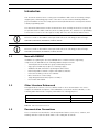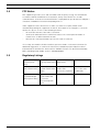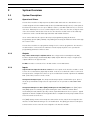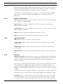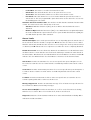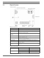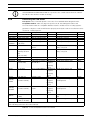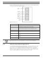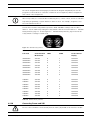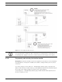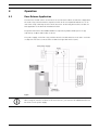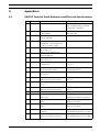
1
Access Control Interface Module
D9210C
en
Installation and Operation Guide
Access Control Interface Module
Table of Contents | en
3
Table of Contents
1
Introduction
5
1.1
New with D9210C
5
1.2
Other Literature Referenced
5
1.3
Documentation Conventions
5
1.4
FCC Notice
6
1.5
Regulatory Listings
6
2
System Overview
7
2.1
System Description
7
2.1.1
Operational Primer
7
2.1.2
Outputs
7
2.1.3
Inputs
7
2.1.4
Reader (Connections)
8
2.1.5
SDI (Connections)
8
2.1.6
Functions
8
2.1.7
Access Levels
9
2.2
Physical Overview
10
2.3
Basic features, displays, and reports
11
2.3.1
Basic features
11
2.3.2
Displays and reports
11
2.4
Materials Included
11
2.5
Ordered Separately
12
2.6
Listings and Approval Information
12
2.6.1
Underwriters Laboratories (UL)
12
3
Installation
13
3.1
System Planning
13
3.2
Procedure
13
3.2.1
Mounting the enclosure and installing the interface module
13
3.2.2
Pulling and Marking the Wires
13
3.2.3
Door Contact (Onboard) Point
15
3.2.4
Door Lock Terminals
17
3.2.5
Request to Enter [RTE]
18
3.2.6
Request to Exit [REX]
18
3.2.7
Connecting the enclosure tamper switch
18
3.2.8
Connecting the card reader
19
3.2.9
Setting the rotary switches and tagging the unit
20
3.2.10
Connecting Power and SDI
21
3.2.11
Programming and activating the interface module
23
3.2.12
Testing the interface module
24
4
Operation
25
4.1
Door Release Application
25
Bosch Security Systems, Inc.
Installation and Operation Guide
F.01U.215.244 | 05 | 2012.06
4
en | Table of Contents
Access Control Interface Module
5
Troubleshooting
26
5.1
LED on Reader
26
A
Appendices
29
A.1
D9210C Terminal Quick Reference and Electrical Specifications
29
F.01U.215.244 | 05 | 2012.06
Installation and Operation Guide
Bosch Security Systems, Inc.
Access Control Interface Module
1
Introduction | en
5
Introduction
This document assumes basic security system installation skills such as measuring voltages,
stripping wire, and making proper wire connections. It also assumes familiarity with the
proper installation of Bosch Security Systems Control/Communicator control panels and the
related programming tasks.
The material and instructions in this document have been carefully checked for accuracy and
are presumed to be reliable. However, Bosch Security Systems, Inc. assumes no responsibility
for inaccuracies and reserves the right to modify and revise this document without notice.
NOTICE!
References made to the D9412 control panel will reflect the following product offerings:
D9412GV4, D9412GV3, D9412GV2, D9412G, D9412.
NOTICE!
References made to the D7412 control panel will reflect the following product offerings:
D7412GV4, D7412GV3, D7412GV2, D7412G, D7412.
1.1
New with D9210C
In addition to replacing the obsolete D9210B micro-controller and it’s supporting
components, the D9210C has the following additional improvements:
1.2
–
Terminal placement modified to group terminals by function.
–
Cage style terminal strip (replaces screw-finger type).
–
Additional 12 VDC terminal for powering 12 VDC readers.
–
Dual rotary address switches replace DIP address switches.
–
Interconnect wiring connector for SDI Bus.
–
More robust door contact relay.
–
Single Wiegand status LED (replaces 2 LEDs).
–
Door Status LED added.
Other Literature Referenced
Throughout this document, references will be made to other documentation. For a more
complete and detailed description of the D9210C Access Control Interface Module, see the
following table that lists the complete part number for ordering purposes.
Name of document
Part Number
D9210C Program Entry Guide
F01U201526
Security System Owner’s Manual
71-06633-000
Table 1.1
1.3
Other Literature Referenced
Documentation Conventions
These conventions are intended to call out important features, items, notes, cautions, and
warnings that the reader should be aware of in reading this document.
Bosch Security Systems, Inc.
Installation and Operation Guide
F.01U.215.244 | 05 | 2012.06
6
1.4
en | Introduction
Access Control Interface Module
FCC Notice
This equipment generates, uses and can radiate radio frequency energy. If not installed in
accordance with the manufacturer’s instructions, it may cause interference to radio
communications. It has been tested and found to comply with the specifications in Subpart J
of Part 15 of FCC Rules for Class B Computing Devices.
If this equipment causes interference to radio or television reception, which can be
determined by turning the equipment on and off, the installer is encouraged to correct the
interference by one or more of the following measures:
–
–
Re-orient the antenna of the radio or television.
Connect the AC transformer to a different outlet so the control panel and radio or
television are on different branch circuits.
–
Relocate the control panel with respect to the radio or television.
If necessary, the installer should consult an experienced radio or television technician for
additional suggestions, or send for the Interference Handbook prepared by the Federal
Communications Commission. This booklet is available from the U.S. Government Printing
Office, Washington DC 20402, stock no. 004-000-00450-7.
1.5
Regulatory Listings
UL 294 (ALVY Access
UL 1076 (APOU:
Control System
Property Alarm Units) Alarm Units)
UL 609 (AOTX: Local
FCC Part 15 Class B
Units)
UL 365 (APAW: Police UL 1610 (AMCX:
UL 864 (UOXX:
CSFM (California
Station Alarm Units)
Central Station Alarm
Control Unit
Office of the State
Units)
Accessories, System)
Fire Marshal)
UL 1023 (NBSX:
UL 985 (UTOU:
Household Burglar
Control Units and
Alarm System Units)
Accessories
Household System
Type)
F.01U.215.244 | 05 | 2012.06
Installation and Operation Guide
Bosch Security Systems, Inc.
Access Control Interface Module
System Overview | en
2
System Overview
2.1
System Description
2.1.1
Operational Primer
7
The interface module is a fully supervised, addressable SDI bus device that allows access
control integration for the D9412 Family (8 doors) and D7412 Family (2 doors) control panels.
Each interface module can store up to 999 user tokens, each with a different access level for
each door. Authority for access is controlled by the level of the user, the time of day, the state
of the door and the armed state of the area to the interface module. Each of the authority
restrictions can be controlled through automatic and manual functions.
Users can be added to the system either by local programming using the Remote
Programming System (RPS), D5200, or by adding tokens using the Add User function through
the control center.
The interface module is not programmed using a local or remote programmer. The interface
module must be connected to the SDI bus to function properly and receive operational
programming parameters and user data.
2.1.2
Outputs
Dry contact SPDT relay for 12/24 V strikes. The relay provides a Normally Closed (NC),
Common (input voltage) and Normally Open (NO) output. When the relay is energized, the
outputs switch to an opposite state.
12 VDC. Provides a connection for a 12 VDC reader or a 12 VDC buzzer.
2.1.3
Inputs
Supervised zone input for the door contact. The zone input on the interface module is used
for the door contact that is physically mounted on the door to which the strike is connected.
The input can be configured for shorts or opens on faults but is normal only when the 1000 kΩ
EOL (end-of-line) resistor is in the circuit.
Unsupervised tamper input. The unsupervised tamper input is normal when open. Upon a
short, the point number assigned to the supervised zone is reported as a MISSING PT###
report.
Unsupervised Request to Enter [RTE] and Request to Exit [REX] inputs. The [RTE] input
and [REX] input are normally open inputs sharing the same common terminal. When
momentarily shorted (500 ms) by a dry contact, input will initiate the door sequence. Typical
applications include a N/O momentary push button or a N/O momentary relay activation from
a Door motion detector device.
The [REX] input generates Door Request to Exit and is used to exit the area assigned to the
interface module without having to use an identification. The [RTE] generates Door Request
to Enter and is used to enter the area assigned to the interface module.
Bosch Security Systems, Inc.
Installation and Operation Guide
F.01U.215.244 | 05 | 2012.06
8
en | System Overview
Access Control Interface Module
Programming REX Shunt Only and RTE Shunt Only allows you to initiate only the shunt and
buzz when the [RTE] or [REX] inputs are shorted. This eliminates the need for a strike and
would be used in applications where a push bar is used to open the door.
It is advisable to assign a point number to the device used to activate the [RTE] and [REX]
inputs, such as an infrared with addressable ZONEX. This ensures that the device is
supervised.
2.1.4
Reader (Connections)
LED. Common upon card read response and strike activation. Sink up to 35 mA from 5-14 VDC
source. Output impedance ia 180Ω.
Buzzer output. Common upon strike activation. Sink up to 35 mA from 5-14 VDC source.
Output impedance is 100Ω.
+5 VDC readers. Power out to 5.2 VDC card reader. V out 5 V +/- .25 V for 20 to 140 mA load,
150 mA maximum continuous.
DATA 0. Data 0 from card reader. High impedance pull up to +/-5.2 V.
DATA 1. Data 1 input from card reader. High impedance pull up to +/-5.2 V.
2.1.5
SDI (Connections)
PWR. Provides power to the interface module and buzzer.
A PANEL DATA. Transports data communications between the interface module and the
security panel.
B PANEL DATA. Transports data communications between the interface module and the
security panel.
COM (Common). Provides electrical common between the interface module and the power
source.
2.1.6
Functions
Normal Door Sequence. The Normal Door Sequence of the interface module is initiated by a
valid access granted (User ID) or door request [RTE/REX]. This initiates the strike, shunt and
buzz time to activate the strike, shunt the point, and create an event reporting the door
sequence has begun.
When the door is held open past the normal door sequence time, an extended door sequence
time is initiated. This extended time extends the shunt and re-activates the buzzer. If
programmed, CLOSE DOOR # will display at the control center assigned to the door. The
normal door sequence will not activate if the interlock point is in an off normal (open or short)
condition.
The Interlock Point can be assigned to multiple door controllers. This is useful for applications
that require doors to not activate when a point is faulted until the interlock point is normal.
Door States. There are four door states for the interface module. These door states can be
controlled through the control center, the Remote Programming System (RPS), scheduled
events (Skeds) and automatic programmable functions in the interface module parameters.
F.01U.215.244 | 05 | 2012.06
Installation and Operation Guide
Bosch Security Systems, Inc.
Access Control Interface Module
System Overview | en
–
Locked Door. This state is considered a normal door state.
–
Unlock Door. This state allows the door to be opened for free access.
–
Secure Door. This state will not allow access unless a Fire Unlock occurs.
–
Fire Unlock. This state allows free access no matter what the previous door state or
9
armed state is. This is a programmable option that can be used to allow free access into
the building upon a fire alarm.
Automatic Functions and Door State. The interface module has two automatic functions that
control door state based on the armed state of the area:
–
Auto Door. With this function as [YES], the door will be unlocked when the area is
disarmed.
–
Disarm on Open. With this function as [YES], a user with valid access rights will activate
the strike and disarm the system after the door is opened. With this function as [NO], the
area will disarm upon the strike activation.
2.1.7
Access Levels
Armed State Rights. Users can be prevented from access depending upon the armed state of
the area that the interface module is assigned to. M indicates the user has access no matter
what the armed state, P indicates the user has access as long as the area is perimeter armed
or disarmed, and D indicates the user only has access when the area is completely disarmed.
Disarm Access Level. Users are allowed to disarm the area with an access identification. Care
should be taken to ensure that the user first has the authority to activate the strike based on
the Armed State. P indicates the user will disarm the area from Master to Perimeter Instant. D
indicates the user will disarm the area from Master or Perimeter to the disarmed state.
Unlock Door. Provides an automatic free access at a specific time period. Requires a Lock
Door Sked to return the door to normal. Can be overridden by manual control at the control
center.
Secure Door. Provides an automatic prevention of access at a specific time period. Requires a
Lock Door Sked to return to normal. Can be overridden by manual control at the control
center.
Lock Door. Provides an automatic lock door state at a specific time to return the door to
normal requiring valid cards or tokens to allow access.
Message Suppression. Provides an automatic message off or on function at a specific time for
Door and Access Granted or No Entry messages.
Access Ctl Level On/Off. Provides an automatic on or off for each of the 14 levels dealing
with the access control. Once a level is turned off, all doors are affected.
Diagnostics. Patterns of LED activation indicate door state and identification validity. Other
indications include SDI failure.
Bosch Security Systems, Inc.
Installation and Operation Guide
F.01U.215.244 | 05 | 2012.06
10
2.2
en | System Overview
Access Control Interface Module
Physical Overview
Figure 2.1 Board Layout
Component
Description
Terminal connector
RGBY wiring connector used to wire PWR, A, B and COM.
Relay LED
Illuminates when the onboard relay is active.
Relay terminals
Provides normally open (N/O) and normally closed (N/C)
connections to the door strike.
Reader and Door
Terminals used for wiring doors and readers to the D9210C.
terminals
Heartbeat LED
System status indicator light signifying whether the D9210C
board is operational or not.
Reader LED
System status indicator light signifying whether the D9210C
board is processing information.
Flash port pins
Used to install firmware to the D9210C using an Update Key.
Rotary Address switches
Two address switches which determine the address for the
module’s address.
Interconnect wiring
Parallel the PWR, A, B, and COM terminals on the terminal
connector
connector.
Table 2.1 Component callouts
LED
Action
State
Heartbeat, blue
LED blinks on and off.
System is operational.
LED is solid on or off.
System is off or not operational.
LED is blinking rapidly.
Card data is executing.
LED is off.
No card data is being received.
Reader, yellow
Table 2.2 Diagnostic and status LEDs
F.01U.215.244 | 05 | 2012.06
Installation and Operation Guide
Bosch Security Systems, Inc.
Access Control Interface Module
System Overview | en
2.3
Basic features, displays, and reports
2.3.1
Basic features
2.3.2
2.4
–
Highly reliable and simple to use.
–
Provides direct interface to 26-bit Wiegand card readers.
–
Onboard buzzer output.
–
Card data LED indicator for card data when valid format is read.
–
Operational LED which indicates the CPU is functioning and unit is powered.
–
Onboard relay for switching 12/24 VDC/VAC power.
–
Option to unlock or lock door upon SDI bus failure.
–
Supervised Onboard point.
–
Request to Exit and Request to Enter inputs that can have a shunt only option.
–
Easily programmable entry and exit door strike and shunt control.
–
Four door states: Locked, Unlocked, Secured, Fire Unlock.
–
Disarm states using a token.
–
Pre-warn for holding door open too long.
–
Disarm system before or after a door opens.
–
Automatic Unlock door on disarm, Locked Door when armed.
–
Optional Deactivate strike when the door opened.
–
Interlock point assignment to prevent access until interlock point is normal.
–
999 Cards or Tokens.
–
Fourteen programmable levels of access authority.
–
Users can be added or deleted remotely, locally and with Command Center.
11
Displays and reports
–
Access Granted with user identification and user name.
–
No Entry with user identification and door user name.
–
Request to Enter with door point text.
–
Request to Exit with door point text.
–
Door Unlocked with door point text.
–
Door Locked with door point text.
–
Alarm Point ### with door point text.
–
Trouble Point ### with door point text.
–
Missing Point ### with door point text.
–
Please Close Door with door point text.
Materials Included
Bosch Security Systems ships the interface module in its own enclosure, or as a unit less
enclosure. You will receive the following parts with your package depending upon what model
is ordered.
–
1 kΩ 1/2 watt end of line resistor.
–
Literature Pack containing: Operation and Installation Guide, Program Entry Guide,
Access Control Interface Module Program Record Sheet.
–
Hardware pack containing: three #6x3/8 self-tapping sheet metal screws to secure the
module on the mounting skirt or the enclosure.
Bosch Security Systems, Inc.
Installation and Operation Guide
F.01U.215.244 | 05 | 2012.06
12
en | System Overview
2.5
Access Control Interface Module
Ordered Separately
The D9210C Door Controller can be used with the Bosch Security Systems D7412 control
panels (supports 2 doors) or D9412 control panels (supports 8 doors). Control panels and
associated keypads are ordered separately.
NOTICE!
Compatible readers are not shipped with the unit. See Section Table 3.3
UL Listed
Compatible Readers for the D9210C, page 19
2.6
Listings and Approval Information
2.6.1
Underwriters Laboratories (UL)
The interface module, when used with D9412 control panels or D7412 control panels, is listed
by UL for use as part of an access control system; local, police-connect, central station, or
proprietary burglar alarm system; household burglar alarm system units; control units and
accessories household system type; and a commercial fire alarm system. The interface module
is a signaling device subassembly also suitable as a burglar alarm unit accessory subassembly, and access control unit sub-assembly.
NOTICE!
In addition to the manual, refer to the D9412/D7412 control panel installation documentation
regarding burglar alarm grades and fire alarm services supported.
F.01U.215.244 | 05 | 2012.06
Installation and Operation Guide
Bosch Security Systems, Inc.
Access Control Interface Module
3
Installation | en
13
Installation
Thank you for choosing our product. We have made an effort to identify the key steps for
installing the interface module. To ensure installation goes smoothly, follow the installation
steps in the order presented.
3.1
System Planning
Before proceeding, Bosch recommends drawing the system layout on a sheet of graph paper.
Also, review the architect and engineering drawings, if available. This will help in setting
addresses, marking the units, and routing and tag wires. The drawing should include the
control panel, the interface module, the trip switches for RTE/REX, doors, readers, control
centers assigned to the same area as the interface modules, and the wiring run.
Have the following documents handy while reading through this manual:
–
Access Control Interface Module Program Entry Guide.
–
Access Control Interface Module Program Record Sheet.
–
Control/Communicator Program Entry Guide and Program Record Sheet.
–
Security System Owner’s Manual.
–
Power Supply Installation Instructions.
Also, become familiar with the operation of the Remote Programming System (RPS) or the
D5200 programmer.
3.2
Procedure
3.2.1
Mounting the enclosure and installing the interface module
Enclosure Placement
–
The maximum distance allowance between the interface module and Wiegand card
readers is 500 feet (152 m).
–
Using 22 AWG (0.8 mm) wire, the interface module may be remoted up to 2500 feet (762
m) away from the control panel; using 18 AWG (1.2 mm) wire, the interface module may
be remoted up to 5000 feet (1524 m).
–
Consider placing the enclosure where a technician can gain easy access for
troubleshooting the unit and where wiring can be routed easily.
3.2.2
Pulling and Marking the Wires
Running wire.
–
Use Table 3.1 Typical Wire Planning Chart for the D9210C to estimate the wire bundle size
for your knockouts and where to mount the interface module.
–
Tag your wire runs to prevent confusion during installation and troubleshooting. Section
Figure 3.1 Wiring Diagram for Typical D9210C installation shows the wiring for a typical
interface module installation.
Bosch Security Systems, Inc.
Installation and Operation Guide
F.01U.215.244 | 05 | 2012.06
14
en | Installation
Purpose
Power/SDI
Access Control Interface Module
Suggested Approximate
Recommended Wire
Recommended Color
Wire Tag
Diameter
Type
Code
Tag A
0.25 in (6.4 mm)
data
4/22 AWG quad(2500 A: (Green)B: (Yellow)
ft/762 m)
PWR: (Red and Black)
4/18 AWG quad(5000
ft/1,524 m)
RTE power/
Tag B
0.25 in (6.4 mm)
4/22 AWG quad
4/22 AWG quad
Tag C
0.25 in (6.4 mm)
4/22 AWG quad
Yellow/Black
Tag D
0.375 in (9.5 mm)
2/16-18 AWG zip
Red
Tag E
0.125 in (3.2 mm)
2/22 AWG(500 ft/152
White
input*
REX power/
input*
Strike
power*
Door
contact*
Reader*
m)
Tag F
0.375 in (9.5 mm)
6/22 AWG
12 VDC: Red5 VDC:
conductor(500 ft/152 OrangeCOM:
m)
BlackD1: WhiteD0:
GreenLED:
BrownBuzzer: Yellow
Buzzer*
Tag G
0.125 in (3.2 mm)
2/22 AWG twist
+(Red), - (Blk)
Emergency
Tag I
0.125 in (3.2 mm)
2/18 AWG twist
Blue
Tag J
0.25 in (6.4 mm)
2/18 AWG zip
Brown
Exit*
Power
Supply
Transformer
* Be sure to multiply the wires by the number of interface modules in the enclosure.
Table 3.1 Typical Wire Planning Chart for the D9210C
F.01U.215.244 | 05 | 2012.06
Installation and Operation Guide
Bosch Security Systems, Inc.
Access Control Interface Module
Installation | en
15
Figure 3.1 Wiring Diagram for Typical D9210C installation
NOTICE!
Do not install or replace an interface module while it is connected to live power circuits. The
interface module should be powered down until it is ready to be tested.
3.2.3
Door Contact (Onboard) Point
ZN+, COM
Description. The interface module monitors the sensor loop for normal, shorted, or open
conditions. This loop is provided for a door contact. The maximum distance the door contact
may be remoted from the interface module is 500 feet. The door contact can be programmed
as a perimeter, interior, or 24 hour burglar alarm point.
Bosch Security Systems, Inc.
Installation and Operation Guide
F.01U.215.244 | 05 | 2012.06
16
en | Installation
Access Control Interface Module
Figure 3.2 Terminal locations
Callout
Description
Callout
Description
Callout
Description
1
PWR
8
T+
15
5.2V
2
A
9
COM
16
DATA0
3
B
10
ZN+
17
DATA1
4
COM
11
RTE
18
BUZZER
5
NC
12
COM
19
LED
6
C
13
REX
7
NO
14
12V
NOTICE!
See the D9210C Access Interface Module Program Entry Guide for assigning a point to the door
controller and the control panel Program Entry Guide for the point types.
Point Sensor Loop. Install a 1 kΩ resistor at the door contact, not at the terminal of the input.
This will provide supervision against grounds on the loop. Connect only one contact, that
being the door, to this input.
Point Tolerance. Section Table 3.2
Point Tolerance Voltages, page 17 shows the voltages
that determine the condition of the on-board point. Use the point common as your (-)
reference when measuring the point (+). Set your meter for 10 to 24 VDC range.
F.01U.215.244 | 05 | 2012.06
Installation and Operation Guide
Bosch Security Systems, Inc.
Access Control Interface Module
Installation | en
Voltage (VDC)
Description
0 - 1.2
Loop shorted
1.8
Coming from a shorted condition, the interface module restores the
17
Door Point at 1.8 VDC
2.65
Normal loop voltage
4.0 - 5.0
Loop open
3.5
Coming from an open condition, the interface module restores the
Door Point at 3.5 VDC
Table 3.2
3.2.4
Point Tolerance Voltages
Door Lock Terminals
NC, C, NO
Description
A relay provides a dry contact single pull double throw output. Some strikes require a closed
circuit to unlock the door while others require an open circuit to unlock the door. The relay
will support 12 VDC @ 2A or 24 VDC @ 2.5 A or 12/24 VAC @ 1A.
Figure 3.3 Terminal locations
Common (C). For 12/24 VDC strikes, provide the input power here from the power supply.
Normally Closed (NC). For door strikes that require an interruption of power to open,
connect the positive side of the door strike to this terminal.
Normally Open (NO). For door strikes that require power to open, connect the positive side
of the door strike to this terminal.
Bosch Security Systems, Inc.
Installation and Operation Guide
F.01U.215.244 | 05 | 2012.06
18
en | Installation
Access Control Interface Module
Figure 3.4 Terminal locations
3.2.5
Request to Enter [RTE]
COM, RTE
Description. When RTE is momentarily shorted to COM, the strike is activated and the door
point is shunted.
Shunt Only. An option is provided that only shunts the point when this input is momentarily
shorted. To activate the shunt, but not the strike, program RTE Shunt Only? as [YES].
3.2.6
Request to Exit [REX]
COM, REX
Description. When REX is momentarily shorted to COM, the strike is activated and the door
point is shunted.
Shunt Only. An option is provided that only shunts the point when this input is momentarily
shorted. To activate the shunt, but not the strike, program [REX] Shunt Only? as [YES].
NOTICE!
A Request to Exit Device (REX) must not be used for emergency exit applications. NFPA 101
requires that a UL listed panic device be used to provide direct power from the standby power
source. Refer to Section Figure 3.1
Wiring Diagram for Typical D9210C installation, page 15
for wiring an emergency exit device. Check with your local Authority Having Jurisdiction (AHJ)
prior to installing your system.
3.2.7
Connecting the enclosure tamper switch
T+, COM
Description. A short to this loop will generate a Missing Trouble Point ### for the point
number assigned to the interface module. With this tamper point faulted, the interface
module will still function.
Connect an N/O tamper switch to T+ and COM. Upon opening the enclosure, the tamper
switch will short the inputs and generate the Missing Trouble Point ### message.
F.01U.215.244 | 05 | 2012.06
Installation and Operation Guide
Bosch Security Systems, Inc.
Access Control Interface Module
Installation | en
19
NOTICE!
SDI FAILURE ### and MISSING PT ### are reported to the central station when the SDI bus
has failed or the interface module is missing.
3.2.8
Connecting the card reader
Description. These terminals provide connection for a standard 26-bit Wiegand reader.
Compatible Readers. Table 3.3, Page 19 specifies the UL listed Wiegand readers and
associated tokens that are compatible with the interface module. Bosch Security Systems
guarantees only these readers will function properly and only the readers noted below can be
used in UL certified systems.
Model
ARD-AYH12
ARD-AYJ12
ARD-AYK12
ARD-AYQ12
ARD-
Power
35 mA (5-16 VDC)
35 mA (5-16 VDC)
35 mA (5-16 VDC)
35 mA (5-16 VDC)
92 mA @ 12 VDC
Description
Tokens
RFID Proximity Reader
RFID Proximity Reader
RFID Proximity Reader
RFID Proximity Reader
RFID with keypad
Cards
Proximity read-only
Proximity read-only
Proximity read-only
Proximity read-only
Proximity read-only
Format
AYCE65B
ARD-R10
(5-16 VDC)
10 to 16 VDC
iCLASS/MIFARE
iCLASS/iCLASS TAG proximity
32-bit
ARD-R40
80 mA/medium
Reader
HID iClass Wall Mount
cards, or key fob
iCLASS/iCLASS TAG proximity
32-bit
cards, or key fob
260 mA peak at 12
VDC
D8223*
D8224
D8224-SP
(10 to 16 VDC)
+12 @ 175 mA
+5 @ 80 mA
30 mA
Proximity, Gray
Proximity, slim, Gray
Low profile Proximity
N/A
D8236 proximity cards
N/A
D8236 proximity cards
D8236KF-10 D8236-10 proximity cards
(5 to 16 VDC)
Card Reader
Wiegand
26-bit
26-bit
26-bit
Proximity
D8225
5 to 16 VDC
Token
HID Prox Mini Mullion D8236KF-10 D8236-10 proximity card
26-bit
Wiegand
Proximity
D8229
1D8201/
+5 @ 120 mA
85 mA maximum
8201W
(12 VDC nominal)
Keypad reader
Low profile reader
Token
N/A
D8238
N/A
D8239/D8239W Wiegand
Wiegand
Proximity Card
26-bit
Proximity
1D8203/
40 mA maximum
Mullion Proximity
Token
D8238
D8239/D8239W Wiegand
D8203W
(12 VDC nominal)
reader
Wiegand
Proximity Card
Proximity
Token
1D8227
35 mA maximum
Insert card reader
D8230-25 Wiegand Magstripe
1D8221
(5 VDC)
40 mA typical
Swipe card reader
Card
D8231-10 Wiegand Swipe Card
(5 VDC to 12 VDC)
* 12 VDC power from interface module source.
1
The following items have been discontinued.
Table 3.3
Bosch Security Systems, Inc.
UL Listed Compatible Readers for the D9210C
Installation and Operation Guide
F.01U.215.244 | 05 | 2012.06
20
en | Installation
Access Control Interface Module
Readers can be mounted up to 500 ft. (152 m) from the interface module. A typical reader
connection is shown in the illustration below.
Figure 3.5 D9210C Terminal
Terminal
Description
COM
The black wire provides the common for the reader. (Use this
terminal when comparing other reader voltages.
12 VDC
The red wire is used to provide 12 VDC readers with power.
Current is limited only by the source providing the power.
5.2 VDC
DATA 0
The orange wire is used to provide 5 VDC readers with power.
The green wire is the carrier of binary one (1) pulses from the
reader.
DATA 1
The white wire is the carrier of binary zero (0) pulses from the
reader.
BUZZER
The yellow wire is the common for the reader buzzer or external
buzzer.
LED
The brown wire is the common for the reader LED.
NOTICE!
LED Terminal can be used for the reader buzzer or common for the external buzzer.
3.2.9
Setting the rotary switches and tagging the unit
The D9412GV4/D9412GV3/D9412GV2/D9412G/D9412 control panels support up to eight
door controllers. The D7412GV4/D7412GV3/D7412GV2/D7412G/D7412 control panel
supports up to two door controllers. Each interface module uses one of eight addresses.
Addresses cannot be duplicated. Because the interface module is always supervised, two
interface modules having the same address will not function correctly.
F.01U.215.244 | 05 | 2012.06
Installation and Operation Guide
Bosch Security Systems, Inc.
Access Control Interface Module
Installation | en
21
Fill out the Program Record Sheet pages (included in the Program Entry Guide). Be sure the
program record for this door controller contains the area assignment, address assignment
and control center assignment.
NOTICE!
Whenever possible, be consistent when numbering doors, control centers, and areas. This will
help when programming a system with more than one door. For example, assign Door 1 to
Area 1 and Control Center 1.
The interface module rotary switches provide a TENS and ONES setting for the module’s
address. Set the address by setting the rotary switches based on Section Table 3.4
Rotary Switches, page 21. Section Figure 3.6
D9210C
D9210C Rotary Switches, page 21 shows the
rotary switches settings for address 81.
Figure 3.6 D9210C Rotary Switches
Serial Device
Fail mode
Central Station
Modem
ONES
Control Center
Display
UNLOCKED
SDI #33
8
1
D9210 #1
UNLOCKED
SDI #34
8
2
D9210 #2
UNLOCKED
SDI #35
8
3
D9210 #3
UNLOCKED
SDI #36
8
4
D9210 #4
UNLOCKED
SDI #37
8
5
D9210 #5
UNLOCKED
SDI #38
8
6
D9210 #6
UNLOCKED
SDI #39
8
7
D9210 #7
UNLOCKED
SDI #40
8
8
D9210 #8
LOCKED
SDI #33
9
1
D9210 #1
LOCKED
SDI #34
9
2
D9210 #2
LOCKED
SDI #35
9
3
D9210 #3
LOCKED
SDI #36
9
4
D9210 #4
LOCKED
SDI #37
9
5
D9210 #5
LOCKED
SDI #38
9
6
D9210 #6
LOCKED
SDI #39
9
7
D9210 #7
LOCKED
SDI #40
9
8
D9210 #8
Table 3.4
3.2.10
TENS
IIIa2
D9210C Rotary Switches
Connecting Power and SDI
CAUTION!
Do not connect 24 VDC or non-isolated [from the strike] 12/24 VAC of the interface module.
Bosch Security Systems, Inc.
Installation and Operation Guide
F.01U.215.244 | 05 | 2012.06
22
en | Installation
Access Control Interface Module
Refer to Section Figure 3.7
Power Supply and SDI Connections, page 23 for the following
connections:
SDI Connection
PWR. Connect the red wire to the SDI terminal. The red wire provides power to the interface
module and buzzers.
A PANEL DATA. Connect the yellow wire to the SDI terminal. The yellow conductor from the
control panel connected to this terminal.
B PANEL DATA IN. Connect the green wire to the SDI terminal. The green conductor from the
control panel is connected to this terminal.
COM (Common). Connect the black wire to the SDI terminal. The black conductor provides
electrical common between the interface module and the power source.
NOTICE!
Always ensure a common terminal connection exists from the interface module to the control
panel so the power supply and control panel have the same ground reference. Use any
common terminal on the interface module silk screen for connections.
F.01U.215.244 | 05 | 2012.06
Installation and Operation Guide
Bosch Security Systems, Inc.
Access Control Interface Module
Installation | en
23
Figure 3.7 Power Supply and SDI Connections
NOTICE!
It is very important to include the strike current. Bosch Security Systems recommends use of
an auxiliary power supply to isolate door controls and ensure the integrity of the system.
3.2.11
Programming and activating the interface module
Description. The interface module needs to be assigned to an area before it can communicate
properly with the control panel. In addition, the address settings and the power need to be
connected.
The rotary settings in Section Table 3.4
D9210C Rotary Switches, page 21 determine the
address of the interface module. At the top of the ACCESS Control Interface Module Program
Record Sheet, the address number noted next to the rotary settings in
Section Figure 3.6
D9210C Rotary Switches, page 21 will determine which parameters for
the door controller are sent.
Bosch Security Systems, Inc.
Installation and Operation Guide
F.01U.215.244 | 05 | 2012.06
24
en | Installation
Access Control Interface Module
To activate the interface module, follow the instructions in the Program Entry Guide. Use the
ACCESS Program Record Sheet to match the door to the proper address and to ensure that
the door is assigned to the proper area.
3.2.12
Testing the interface module
Description. The interface module comes shipped with a default program that allows a quick
test run upon installing the unit. Go through the following items to verify the interface module
is functioning properly. If problems arise, refer to Section 5 Troubleshooting, page 26
Interface Module. Verify that the Heartbeat LED is pulsing approximately once every second.
This indicates the microprocessor is running. Go to the Unlock Door function. A number from
1 to 8 should appear for the door controller. If an F appears, the unit has failed or is not
responding correctly to the control panel’s polls.
Zone. Using the keypad, verify the point is normal when the door is closed, the point goes off
normal when the door is opened and a shunt is not applied, and that the point stays normal
upon opening the door on a valid access granted.
Strike. Read a valid token to activate the strike. If tokens have not been added, use the Door
Control, Door Unlock mode to cycle the strike. In addition, you will cycle the strike when you
test the [RTE/REX] inputs (if shunt only is not programmed [YES].
RTE/REX. Fault these inputs to activate the strike. The default for the strike time is 10
seconds. Test each separately.
Buzzer. The buzzer should have sounded on each strike activation. Also hold the door open
past the normal shunt time and ensure the Extend Buzz functions.
Reader. Depending on the reader, the reader LED will be red upon powering up the interface
module. During the above tests, it will turn green anytime the strike is activated.
To verify the reader, check that the Reader LED blinks rapidly while a card is passed through
the reader or a token is held up to the proximity reader. Review the instructions that come
with the specific reader for more information on operational use.
NOTICE!
For other LED functionality, refer to Section 5 Troubleshooting, page 26.
F.01U.215.244 | 05 | 2012.06
Installation and Operation Guide
Bosch Security Systems, Inc.
Access Control Interface Module
Operation | en
4
Operation
4.1
Door Release Application
25
The interface module can be used for door release functions. When used in this configuration,
the strike relay contacts must be supervised. This can be accomplished with the use of an
end-of-line relay commonly used for smoke detectors. Connecting the interface module for
this application is shown in the illustration below.
Program Point Index in the POINTS handler as Supervisory with Point Response as [A]
Supervisory on Open and Trouble on Short.
The power supply, end-of-line relay, and the interface module must be in the same enclosure
or adjacent enclosures connected via conduit not longer than 20 feet (6 m).
Figure 4.1 D9210C Door Release Application Connections
NOTICE!
When using the interface module for the Door Release, you must use the D8004 Transformer
Enclosure for the power supply.
Bosch Security Systems, Inc.
Installation and Operation Guide
F.01U.215.244 | 05 | 2012.06
26
en | Troubleshooting
Access Control Interface Module
5
Troubleshooting
5.1
LED on Reader
Use the LED Troubleshooting Guide and the LED on the reader patterns to troubleshoot the
interface module. It is important to use the Door Control function to validate actual door
states when troubleshooting.
F.01U.215.244 | 05 | 2012.06
Installation and Operation Guide
Bosch Security Systems, Inc.
Access Control Interface Module
Reader Action
Troubleshooting | en
If Reader LED is
then Door State is
27
so LED will toggle
Idle reader LED
Red
Locked
Red
Secured
Green
Unlocked
Continuous Red/
Locked on Fail
Green
(Rotary address
D9210C is not
switch
programmed with an
optional)Unlocked on
area, D9210C faulty.
SDI disconnected,
Fail (Rotary address
switch optional)
Access Granted
Red: Valid token to
Locked
activate strike.
Red to Green for
duration of strike
time.
Unlocked
Green: Valid token
Green to Red to
Green
will not activate strike
because strike is
latched to allow
access.
Access Denied
Red: Valid token
Locked
format not added.
Red to Green to Red
(pattern repeats
twice)
Red: Valid token but
Locked
level is turned off.
Red to Green to Red
(pattern repeats
twice)
Red: No access
Secured
Red to Green to Red
allowed regardless of
(pattern repeats
level because door is
three times)
secured.
Custom Function
Red: Valid token will
Locked/Secured
run.
Red to 1 second
Green to Red
Green: Valid token
Unlocked
will run.
Green to 1 second
Red to Green
Adding IDs
Red: Adding new
Learn Mode while
Red to 2 second
token
door is secured or
Green back to Red
locked.
Red: Changing token
Learn Mode while
Red to Green to Red
that exists.
door is secured or
to Green to Red
locked.
Bosch Security Systems, Inc.
Installation and Operation Guide
F.01U.215.244 | 05 | 2012.06
28
en | Troubleshooting
Access Control Interface Module
Reader Action
If Reader LED is
then Door State is
so LED will toggle
Green: Changing
Learn Mode while
Green to 1 second
token that exists.
door is unlocked.
Red to Green
Green: Adding new
Learn Mode while
Green to 2 second
token
door is unlocked.
Red to Green
Table 5.1 LED Troubleshooting Guide
F.01U.215.244 | 05 | 2012.06
Installation and Operation Guide
Bosch Security Systems, Inc.
Access Control Interface Module
| en
29
A
Appendices
A.1
D9210C Terminal Quick Reference and Electrical Specifications
#
Terminal
Description
Electrical Specifications
1
PWR
12 VDC power input
8.5 - 13.8V [depending on reader
draw: 110 mA (board) + 150 mA
(reader max) = 260 mA]
2
3
A
B
Data from the control panel
High impedance bi-directional
to the D9210C
differential bus
Data back to the control panel
RS-485 @ 9600 baud
from the D9210C
4
COM
Common for connection to
SDI COM on control panel and
common on power supply
5
NC
Continuity with LCK COM
12/24 V @ 2.0 A max (30 VDC max)
when relay is off
6
C
Input to feed LCK N/C (T2)
and Lock N/O (T3)
7
NO
Continuity with LCK COM
12/24 V @ 2.0 A max (30 VDC max)
when relay is on.
8
9
T+
COM
Positive input for Tamper,
Input 1 kΩ pull upV in < 1.8 V on >
normally open
3.2 V off
Common for on-board
1K Ω termination resistor between
point and tamper inputs
10
ZN+
T9 and T10 required
Positive Input for on-board
point (zone)
11
12
RTE
COM
Input from Request to Enter
Input 1kΩ pull upV in < 1.8 V on >
(RTE) momentary short device
3.2 V off
Common input for REX/RTE
devices
13
REX
Input from Request to Exit
Input 1 kΩ pull upV in < 1.8 V on >
(REX) momentary short device
3.2 V off
14
12 VDC
Power for 12V reader
8.5-13.8V
15
+5.2VDC
Power out to 5.2 VDC
V out 5 V+/_ .25 V for 20 - 140 mA
card reader
load150 mA maximum continuous
16
17
18
19
Bosch Security Systems, Inc.
DATA 0
DATA 1
BUZZER
LED
Data 0 input from card
High impedance inputs with 47kΩ
reader
pull up to +5.2 VDC
Data 1 input from card
High impedance inputs with 47kΩ
reader
pull up to +5.2 VDC
Buzzer common upon strike
Sink up to 35 mA from 5 - 14 VDC
activation
sourceOutput impedance is 100 Ω
LED common upon card read
Sink up to 35 mA from 5 - 14 VDC
response and strike activation
sourceOutput impedance is 180Ω
Installation and Operation Guide
F.01U.215.244 | 05 | 2012.06
30
en |
F.01U.215.244 | 05 | 2012.06
Access Control Interface Module
Installation and Operation Guide
Bosch Security Systems, Inc.
Bosch Security Systems, Inc.
130 Perinton Parkway
Fairport, NY 14450
USA
www.boschsecurity.com
© Bosch Security Systems, Inc., 2012