1
INSTRUCTION MANUAL
Precision Integrating Sound Level Meter
with 1/3 octave band real-time analyzer
NA-27
3-20-41 Higashimotomachi, Kokubunji, Tokyo 185-8533, Japan
http://www.rion.co.jp/english/
Organization of This Manual
This manual describes the features, operation and other aspects of the Precision Integrating
Sound Level Meter with 1/3 octave band real-time analyzer NA-27. If the unit is used together
with other equipment to configure a measurement system, consult the documentation of all
other components as well. The following pages contain important information about safety.
Be sure to read and observe these in full.
This manual contains the following sections.
Outline
Gives basic information about the unit. Also contains information about items that are
not covered in other sections.
Controls and Functions
Briefly identifies and explains the controls and connectors and all other parts of the unit.
Preparations
Explains how to insert the backup battery and main batteries, how to make connections,
set the date and time, calibrate the unit, and use the menu screens.
Setting Measurement Parameters
Explains how set the basic parameters before starting sound pressure level measurement
and analysis.
Sound Pressure Level Measurement
Explains the operation steps for performing sound pressure level measurement.
1/1-Octave and 1/3-Octave Analysis
Explains the operation steps for performing 1/1 and 1/3 octave analysis.
Data Exclusion (Back-Erase) Function
Explains how to exclude (back-erase) data from a short period before the measurement
was paused.
Trigger Function
Explains how to start the sound pressure level measurement using the trigger mode.
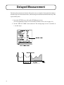
Delayed Measurement
Explains how to perform delayed measurement.
Memory Functions
Explains how to store measurement results in the memory of the unit.
i
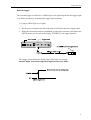
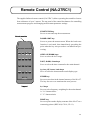
Remote Control (NA-27RC1)
Explains the names and functions of the operation buttons on the panel of the remote
control.
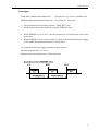
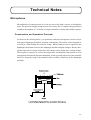
Technical Notes
Provides information about the microphone, preamplifier, basic configuration of the sound
level meter, and measurement functions.
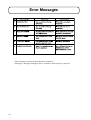
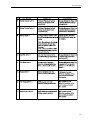
Error Messages
Lists error message that can appear during startup, as well as suitable countermeasures.
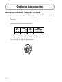
Optional Accessories
Explains how to use the optional accessories available for the unit.
Specifications
Lists the technical specifications of the unit.
EMC DIRECTIVE
The NA-27 described in this manual is in conformity with the
following International Standard;
IEC 61672 - 1:2002 Class1 (Sound level meter)
To conform to the EU requirement of the Directive
2002/96/EC on Waste Electrical and Electronic
Equipment, the symbol mark on the right is shown
on the instrument.
* Company names and product names mentioned in this manual are usually trademarks or
registered trademarks of their respective owners.
ii
FOR SAFETY
In this manual, important safety instructions are specially marked as shown below. To prevent the
risk of death or injury to persons and severe damage to the unit or peripheral equipment, make sure
that all instructions are fully understood and observed.
Caution
Important
Disregarding instructions
printed here incurs the risk of
injury to persons and/or damage to peripheral equipment.
Disregarding instructions
printed here incurs the risk of
damage to the product.
12345678901234567890123456789012123456789012345678901234567890121234567890123
12345678901234567890123456789012123456789012345678901234567890121234567890123
12345678901234567890123456789012123456789012345678901234567890121234567890123
12345678901234567890123456789012123456789012345678901234567890121234567890123
Note
Mentioned about the tips to use
this unit properly. (This messages do not have to do with
safety.)
iii
iv
Precautions
z Operate the unit only as described in this manual.
z The NA-27 is a precision instrument. Protect it from shocks and vibrations. Take special care not to touch the microphone diaphragm. The diaphragm is a very thin metal
film which can easily be damaged.
z Use only the microphone/preamplifier assembly with the number as shown on the
name plate of the unit.
z Ambient conditions for operation of the unit are as follows: temperature range -10 to
+50ºC, relative humidity 30 to 90%.
Protect the unit from water, dust, extreme temperatures, humidity, and direct sunlight
during storage and use. Also keep the unit away from air with high salt or sulphur
content, gases, and stored chemicals.
z Always turn the unit off after use. Remove the batteries from the unit if it is not to be
used for a long time (a week or more). When disconnecting cables, always grasp the
plug and do not pull the cable.
z Before using the microphone and before putting it away, always check that the microphone grid has not become loose. If this has happened, refasten the microphone grid
firmly and then use or store the microphone.
z Clean the unit only by wiping it with a soft, dry cloth or, when necessary, with a cloth
lightly moistened with water. Do not use any solvents, cleaning alcohol or chemical
cleaning agents.
z Do not tap the LCD panel or other surfaces of the unit with a pointed object such as a
pencil, screwdriver, etc.
z Take care that no conductive objects such as wire, metal scraps, conductive plastics
etc. can get into the unit.
z Do not try to disassemble or alter the unit. Otherwise type certification will become
invalid. In case of an apparent malfunction, do not attempt any repairs. Note the condition of the unit clearly and contact the supplier.
z To ensure continued precision, have the unit checked and serviced at regular intervals.
z When disposing of the unit or the accessories, follow national and local regulations
regarding waste disposal.
v
Contents
FOR SAFETY ...................................................................................................iii
Outline ................................................................................................................ 1
Controls and Functions .................................................................................. 4
Carrying Case and Accessories ..................................................................... 4
Top View ...................................................................................................... 6
Side View.................................................................................................... 10
Rear View ................................................................................................... 12
Bottom View ............................................................................................... 13
Measurement Screen ................................................................................... 14
Preparations .................................................................................................... 16
Backup Battery............................................................................................ 16
Power Supply .............................................................................................. 18
Tripod (option) Mounting ........................................................................... 21
Trigger Input ............................................................................................... 23
Using the Backlight .................................................................................... 23
Display Contrast ......................................................................................... 23
Setting the Date and Time .......................................................................... 24
Calibration .................................................................................................. 26
Using the Menu Screens ............................................................................. 30
Menu Screens.............................................................................................. 32
Factory Default Settings ............................................................................. 34
Setting Measurement Parameters.............................................................. 36
Sound Pressure Level Measurement ......................................................... 42
Instantaneous Sound Pressure Level Measurement (LA, LC, Lp) ................ 43
Maximum and Minimum Sound Pressure Level Measurement
(Lmax, Lmin) ............................................................................................ 46
Waveform Peak Hold Measurement (Lpeak) ................................................ 48
Equivalent Continuous Sound Pressure Level Measurement (Leq)............. 51
Sound Exposure Level Measurement (LAE) ................................................ 53
vi
Takt-Max Sound Pressure Level Measurement (Ltm3, Ltm5) ....................... 54
Percentile Sound Pressure Level Measurement (Lx)................................... 57
1/1-Octave and 1/3-Octave Analysis ......................................................... 59
1/1-Octave and 1/3-Octave Analysis for Instantaneous Value
(LA, LC, Lp) ............................................................................................ 59
1/1-Octave and 1/3-Octave Analysis for Maximum and Minimum Level
(Lmax, Lmin) ........................................................................................... 60
1/1-Octave and 1/3-Octave Analysis for Equivalent Continuous
Sound Pressure Level (Leq) ................................................................... 61
1/1-Octave and 1/3-Octave Analysis for Percentile Sound Pressure Level
(Lx) ....................................................................................................... 62
Explanation of Analysis Screens ................................................................ 63
1/1-Octave and 1/3-Octave Analysis Precaution ........................................ 65
Data Exclusion (Back-Erase) Function .................................................... 66
Trigger Function ............................................................................................ 68
Delayed Measurement .................................................................................. 74
Memory Functions ......................................................................................... 76
Manual (Sound Pressure Level Mode) ....................................................... 78
Auto (Sound Pressure Level Mode) Single Store ....................................... 81
Auto (Sound Pressure Level Mode) Group Store ....................................... 84
Manual (Frequency Analysis Mode)........................................................... 87
Auto (Frequency Analysis Mode) Single Store .......................................... 89
Auto (Frequency Analysis Mode) Group Store .......................................... 93
Erasing Data ................................................................................................ 98
Recall Processing ........................................................................................ 99
Remote Control (NA-27RC1) ........................................................................ 101
Technical Notes ............................................................................................ 103
Microphone ............................................................................................... 103
Preamplifier .............................................................................................. 108
Preamplifier Specifications ....................................................................... 108
vii
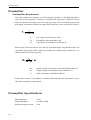
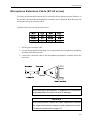
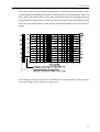
Microphone Extension Cable (EC-04 series) ........................................... 109
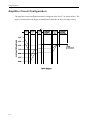
Amplifier Circuit Configuration ............................................................... 112
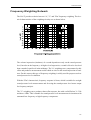
Frequency Weighting Network ................................................................. 113
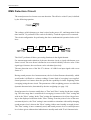
RMS Detection Circuit ............................................................................. 114
Measurement Functions ............................................................................ 117
Noise Floor ............................................................................................... 120
Background Noise..................................................................................... 121
Windscreen (WS-02) ................................................................................ 122
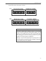
I/O Connector ........................................................................................... 125
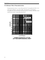
1/1-Octave Filter Characteristics .............................................................. 126
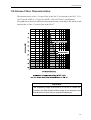
1/3-Octave Filter Characteristics .............................................................. 127
Error Messages............................................................................................. 128
Optional Accessories ................................................................................... 130
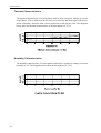
Microphone Extension Cables (EC-04 series) .......................................... 130
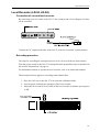
Level Recorder (LR-04, LR-06) ............................................................... 131
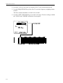
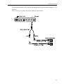
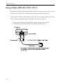
Using a Printer (DPU-414, CP-10, CP-11) ............................................... 134
Specifications ................................................................................................ 140
viii
Outline
The precision integrating sound level meter NA-27 allows digital 1/1-octave and 1/3octave analysis in real time. It conforms to legal requirements for quantity measurements
and to JIS and IEC standards. Using the output signal from a single microphone, the
NA-27 can determine values for different time constants and frequency weighting settings
simultaneously.
In addition to conventional noise level and sound pressure level measurements, the NA-27
can also determine the following quantities:
z
z
z
z
z
z
z
z
z
z
Equivalent continuous sound pressure level Leq
Sound exposure level LE
Maximum sound pressure level Lmax
Minimum sound pressure level Lmin
Percentile sound pressure level Lx
Takt-max sound pressure level (3 or 5 s) Ltm3, Ltm5 *
Waveform peak sound pressure level Lpeak
Power average P_AVE
Power sum P_SUM
Reverberation time REVERB
* Taktmaximalpegel Mittelwert: DIN
Power averaged maximum sound pressure level in a measuring period
Measurement data can be stored in the large-capacity internal memory of the NA-27.
These data can be sent to a computer, using the built-in serial port and a high-speed block
transfer protocol. In addition, an optical port allows data collection and data transfer under
computer control, and an infrared remote control unit is also supplied.
1
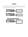
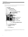
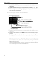
Outline
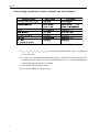
Processing functions in main channel and sub channel
*1 Lmax, Lmin, Leq, LE, Ltm3, Ltm5 are calculated simultaneously from Lp sampled at
10 ms intervals.
*2 Lx values are calculated simultaneously from Lp sampled at 100 ms intervals for
measurement times up to 1 h. For measurement times over 1 h, the sampling interval increases by 100 ms for every hour.
*3 Set with the SETUP menu screen.
*4 Set with the DISPLAY menu screen.
2
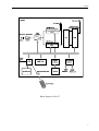
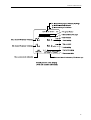
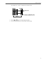
Outline
Block diagram of NA-27
3
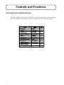
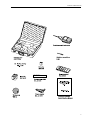
Controls and Functions
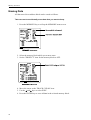
Carrying Case and Accessories
The unit is supplied with the parts listed below. Verify that all parts are complete and that
there is no damage. If any parts are missing or damaged, please contact the supplier.
4
Controls and Functions
5
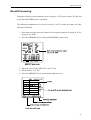
Controls and Functions
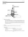
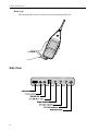
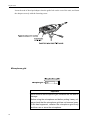
Top View
Microphone/preamplifier
The microphone and preamplifier are configured as an integrated assembly. The microphone and preamplifier are labeled with a serial number which must match the number
shown on the rear of the main unit. The microphone/preamplifier assembly can be
removed from the sound level meter and connected via an optional extension cable, for
measurements a distance.
Display
The backlit liquid crystal display has a resolution of 192 × 192 dots.
LED indicator
This indicator signals the following conditions.
Overload:
Overload occurred in the main channel.
Measurement:
Indicator flashes in 1 second intervals.
Remote control signal reception: Indicator flashes 3 times in 0.2 to 0.3 second intervals.
6
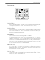
Controls and Functions
Operation keys
START/STOP key
Press to start and to terminate the sound pressure level measurement (including the
various processing functions). The key is also used to store data in memory.
PAUSE/CONT key
Serves to temporarily pause and resume the measurement. When the data exclusion
(back-erasing) function is used, data for a certain number of seconds before the key was
pressed can be excluded from processing.
OPE MODE key
Serves to call up the various processing results on the display.
For the main channel, possible display items are instantaneous value (Lp), equivalent
continuous sound pressure level (Leq), sound exposure level (LE), maximum sound
pressure level (Lmax), minimum sound pressure level (Lmin), and percentile sound pressure level (Lx). For the sub channel, the takt-max sound pressure level (Ltm3, Ltm5), and
the waveform peak hold level (Lpeak) can be displayed.
GRP/NUM/L-T key
In 1/1 octave and 1/3 octave mode, this key switches the display function between
graphical and numeric indication. When showing data stored in memory, the key can
be used to show the level-time indication.
SLM / 1/1 / 1/3 key
This key switches the operation mode between sound level meter (SLM), 1/1 octave
analysis (1/1), and 1/3 octave analysis (1/3).
7
Controls and Functions
CAL key
Pressing this key activates the built-in oscillator for electrical calibration of the NA-27
or for level matching of the NA-27 and connected equipment.
FREQ WEIGHT key
Selects the frequency weighting characteristic for the main channel. Available settings
are "A" weighting (A), "C" weighting (C), and flat frequency response (FLAT).
The frequency weighting characteristics for the sub channel are set with the SETUP
menu screen.
TIME CONST key
Selects the time weighting (time weighting) for the main channel. Available settings
are "FAST", "SLOW", "35 ms" and "10 ms". The time weighting for the sub channel is
set with the SETUP menu screen.
LEVEL UP
LT
key
Serves to select the level range. The level range cannot be set individually for the main
channel and sub channel. When showing the level-time display (from data stored in the
internal memory), the key serves to expand the time axis.
LEVEL DOWN
LT
key
Serves to select the level range. The level range cannot be set individually for the main
channel and sub channel. When showing the level-time display (from data stored in the
internal memory), the key serves to contract the time axis.
STORE key
Serves to start and stop the store process for entering data into the memory.
RECALL key
Switches the unit between the mode for recalling data from the memory (recall mode)
and the measurement data display mode (current mode).
INC, DEC keys
Serve to increase or decrease numerical values of the various menu entry items. When
data are being stored into the memory or displayed from memory, the keys serve to
select address numbers.
keys
Serve to select items from the menu screens.
8
Controls and Functions
keys
Serve to move the marker during frequency analysis. When a menu is displayed, the
keys serve to select parameters.
ENTER key
When a menu is displayed, the key serves to accept a setting.
PRINT key
Serves to start and stop printout of the current measurement screen or of data stored in
memory on a connected printer (DPU-414, CP-10, CP-11; option).
SETUP key
Pressing this key calls up the SETUP menu screen, for setting measurement parameters. Pressing the key once more returns to the measurement screen.
MEMORY key
Pressing this key calls up the MEMORY menu screen, for setting memory parameters.
Pressing the key once more returns to the measurement screen.
DISPLAY key
Pressing this key calls up the DISPLAY menu screen, for setting display parameters.
Pressing the key once more returns to the measurement screen.
I/O key
Pressing this key calls up the I/O menu screen, for setting input/output parameters.
Pressing the key once more returns to the measurement screen.
Optical port
This optical port allows sending measurement data over an infrared link to a computer
equipped with a suitable infrared port.
Remote control sensor
The signals from the remote control unit (NA-27RC1) are received here, allowing operation of the unit from a distance of up to 3 meters.
9
Controls and Functions
Hand strap
The strap should be used to safely carry the unit during field work.
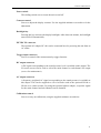
Side View
10
Controls and Functions
Power switch
This sliding switch serves to turn the unit on and off.
Contrast control
Serves to adjust the display contrast. Use the supplied miniature screwdriver for the
adjustment.
Backlight key
Pressing this key activates the display backlight. After about one minute, the backlight
turns itself off automatically.
EXT DC IN connector
The optional AC adapter NC-94A can be connected here for powering the unit from an
AC outlet.
Trigger input connector
Serves to control of the measurement by trigger function.
DC output connector
A DC signal corresponding to the sound pressure level is available at this output. The
I/O menu screen can be used to select the main channel or sub channel for output
(serves for maintenance).
AC output connector
A frequency-weighted AC signal corresponding to the sound pressure is available at
this output. This can be supplied to a level recorder such as the optional LR-04 or
LR-06 or to a data recorder. By using the optional splitter adapter, a separate signal
for the main channel and sub channel can be obtained.
Calibration control
Serves to carry out calibration, using the supplied miniature screwdriver.
11
Controls and Functions
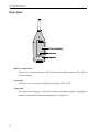
Rear View
Battery compartment
The unit uses four main batteries (IEC R14P) and one lithium battery (CR-1/3N) for
memory backup.
Guide hole
This hole serves to fasten the supplied tripod adapter NA-27-S05.
Name plate
The model name and type, certification number, microphone number, preamplifier
number, serial number, and manufacturing date are shown here.
12
Controls and Functions
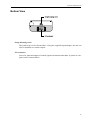
Bottom View
Strap fastening screw
The hand strap is to be fastened here. Using the supplied tripod adapter, the unit can
also be mounted on a camera tripod.
I/O connector
Serves for input and output of control signals and measurement data. A printer or computer can be connected here.
13
Controls and Functions
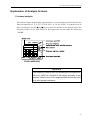
Measurement Screen
The actual appearance of the measurement screen depends on the selected measurement
parameters. A representative example is shown below.
The illustration shown above may differ slightly from the actual screen display of the unit,
regarding fonts, character size etc.
14
Controls and Functions
15
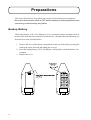
Preparations
This section describes the steps which are necessary before starting a measurement.
Be sure to set the power switch to OFF before inserting or removing batteries and
connecting or disconnecting any cables.
Backup Battery
The backup battery (CR-1/3N, lithium) serves to maintain settings and data stored in
memory also while the unit is turned off. In normal use, a backup battery should always be
inserted. Proceed as described below.
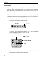
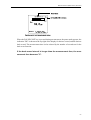
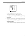
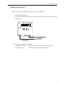
1. Remove the cover of the battery compartment on the rear of the unit by pressing the
latch in the arrow direction and lifting the cover up.
2. Insert the backup battery (CR-1/3N, lithium), with polarity as indicated in the compartment.
3. Replace the cover.
16
Preparations
Important
The life of the backup battery is about two years. To be on the
safe side, you should replace the battery every 1 to 1-1/2
years.
When the battery is removed, all stored data as well as the
time and date settings are lost. If necessary, use the printer
DPU-414, CP-10 or CP-11 to print out settings and data before changing the battery. After replacement, set the clock
and date again, as described on page 24.
The backup battery serves to maintain stored data and to
power the internal clock. Since this is not mandatory for
measurements, sound pressure level measurement and frequency analysis are possible also without the backup battery.
Replacing the backup battery (lithium battery)
1. Turn power to the unit off.
2. Remove the old lithium battery.
3. Wait at least two minutes, and then insert the new lithium battery.
Note
If you insert the new battery within two minutes after removing the old battery, the unit may not operate correctly the
next time it is turned on.
4. Turn power to the unit on. The unit will come on with the factory default settings
(page 34).
17
Preparations
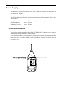
Power Supply
The unit can be powered by four IEC R14P (size C) batteries (alkaline or manganese) or
the optional AC adapter.
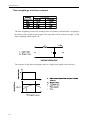
The life of the batteries depends on various usage factors. Representative figures are
shown below.
Battery life (at room temperature, 1/3-octave analysis, continuous operation)
Alkaline batteries:
approx. 8 hours
Manganese batteries:
approx. 4 hours
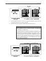
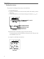
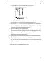
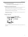
Inserting the batteries
To power the unit from batteries, insert four IEC R14P (size C) batteries into the battery
compartment, paying attention to correct polarity.
When inserting a battery, press it against the spring on the negative pole side and snap the
battery into place. To remove a battery, push it towards the negative pole and lift it up on
the positive side.
18
Preparations
Important
Take care not to reverse the (+) and (-) polarity when inserting a battery.
Always use four identical batteries, and replace batteries
only as a set. Mixing battery types or old and new batteries
can lead to damage.
Remove the batteries from the unit if it is not to be used for a
week or longer.
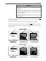
When the battery voltage drops near the operation limit of the unit, the indication LOW
appears on the display.
In this case, replace all four batteries with fresh ones at the earliest opportunity.
When the battery voltage drops even further, the indication EMP flashes on the display.
You must immediately replace all four batteries with fresh ones if you want to continue
using the unit.
19
Preparations
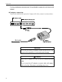
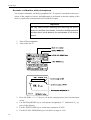
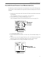
For long continuous measurements, it is preferable to power the unit from the AC
adapter.
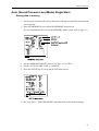
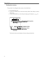
AC adapter connection
To power the unit from the optional AC adapter (NC-94A), connect it as shown below.
Important
Do not use any other AC adapter except the optional NC-94A
to prevent the possibility of overheating and damage.
Caution
While the AC adapter is in use, do not coil or bend the power
cable.
Do not cover the AC adapter or power cable with paper,
cloth or the like. Otherwise overheating may occur.
20
Preparations
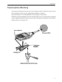
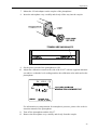
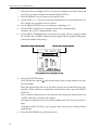
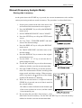
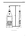
Tripod (option) Mounting
For long-term measurements, the unit can be mounted on the sound level meter tripod
ST-80 (option). In this case, the supplied tripod adapter is required.
Proceed carefully, to avoid dropping the unit or tipping over the tripod.
Wind noise at the microphone can cause measurement errors. To prevent this, you should
use the supplied windscreen WS-02 in cases where wind may be a problem. (For technical
details, please refer to page 122.)
21
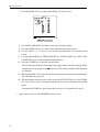
Preparations
Insert the stud of the tripod adapter into the guide hole on the rear of the unit, and fasten
the adapter securely with the fastening screw.
Microphone grid
Important
Never remove the microphone grid, because this can lead to
damage.
Before using the microphone and before putting it away, always check that the microphone grid has not become loose.
If this has happened, refasten the microphone grid firmly
and then use or store the microphone.
22
Preparations
Trigger Input
An external trigger signal can be used to initiate the measurement (see page 68). Use a
logic-level signal or shorten the trigger connector.
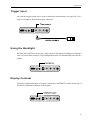
Using the Backlight
Pressing the LIGHT key on the side of the unit turns the display backlight on, making it
easier to read in dark locations. The backlight shuts itself off automatically after about a
minute.
Display Contrast
Using the supplied miniature screwdriver, adjust the CONTRAST control on the side of
the unit for optimum readability of the display.
23
Preparations
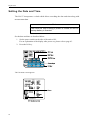
Setting the Date and Time
The NA-27 incorporates a clock which allows recording the date and time along with
measurement data.
Note
The clock will stop running if power is turned off and no
backup battery is inserted.
Set the date and time as described below.
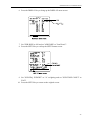
1. Set the power switch on the side of the unit to ON.
For an explanation of the display after power-on, please refer to page 43.
2. Press the I/O key.
The I/O menu screen appears.
24
Preparations
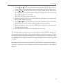
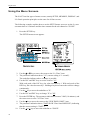
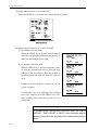
3. Use the and keys to move the flashing cursor to the "DATE" item. The currently set date (such as 96/04/08) is shown in the bottom left corner of the screen.
4. Use the and keys to move the cursor to the year, month, and day field. Use the
INC and DEC keys to set the numbers. Make the setting in the order year, month,
day, using two digits for each field.
Enter only the last two digits for the year.
5. When the setting is correct, press the ENTER key. The date is set and the cursor
moves to the "TIME" indication.
6. Use the and keys to move the cursor to the hour and minute field. Use the INC
and DEC keys to set the numbers. Enter the time in 24-hour notation.
7. When the setting is correct, press the ENTER key. At this point, the clock starts
moving from 00 seconds.
8. Press the I/O key once more to return to the previous screen.
If no backup battery is inserted in the unit, the indication "Backup Battery Empty!!" appears after turning on the power. Insert a backup battery as described on page 16. When
wishing to use the unit without a backup battery, simply press any key to make the indication disappear. In this case, the memory store function and date and time functions are not
available.
If the date and time are not set, the indication "RTC Read Error!!" appears after turning on
the power. In this case, use the I/O menu screen to set the date and time, as described on
page 24.
25
Preparations
Calibration
Before starting a measurement, the NA-27 must be calibrated. There are two types of
calibration, namely electrical calibration and acoustic calibration using a pistonphone.
When compensation for atmospheric pressure is not required, it suffices to perform electrical calibration only.
Electrical calibration
Calibration is carried out by setting the unit to the CAL mode. If the display reads 94.0 dB,
calibration was completed successfully. If the reading is different, or if level calibration of
connected equipment is required, perform the following steps.
1. Set the power switch on the side of the unit to ON.
2. Use the SLM / 1/1 / 1/3 key to call up the measurement screen.
3. Press the CAL key to activate the calibration mode.
At this point, frequency weighting is temporarily set to "C"; it will return to the
original setting when the CAL key is pressed once more.
4. Use the LEVEL UP/DOWN keys to set the measurement range to 100.
If the measurement range is set to a value other than 100, the CAL indication
flashes and correct calibration cannot be carried out.
26
Preparations
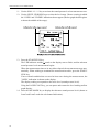
5. Use the supplied miniature screwdriver to adjust the calibration control on the side
of the unit so that the level reading is 94.0 dB.
6. Press the CAL key once more to return to the measurement screen.
Note
The calibration control is a multi-turn type. The value may
not change on a single turn.
If a measurement is currently in progress (indicated by the
"measurement in progress" triangle or the "pause" mark), or
if a menu screen is currently shown, calibration cannot be
carried out. Wait until the measurement is completed (or
press the START/STOP key), or terminate the menu screen
before initiating calibration.
27
Preparations
Acoustic calibration with pistonphone
For acoustic calibration, the Rion pistonphone NC-72 (option) is mounted to the microphone of the sound level meter, and adjustment is performed so that the reading of the
meter is equal to the sound pressure level inside the coupler.
Important
Be very careful when inserting and removing the microphone to and from the coupler, to avoid a sudden pressure
buildup which could destroy the membrane of the microphone.
1. Turn off the pistonphone.
2. Turn on the NA-27.
3. Press the SLM / 1/1 / 1/3 key to call up the sound pressure level measurement
screen.
4. Use the FREQ/WGHT key to set frequency weighting to "C" (indication "Lc" appears on the display).
5. Use the TIME CONST key to set the time constant to "FAST".
6. Use the LEVEL UP/DOWN keys to set the level range to "120".
28
Preparations
7. Mount the 1/2-inch adapter on the coupler of the pistonphone.
8. Insert the microphone very carefully and slowly all the way into the coupler.
9. Set the power switch of the pistonphone to ON.
10. Adjust the calibration control on the side of the NA-27 with the supplied miniature
screwdriver so that the level reading matches the calibration value indicated on the
pistonphone.
For information on compensation for atmospheric pressure, please refer to the instruction manual of the pistonphone.
11. Turn off the pistonphone and the NA-27.
12. Remove the microphone very carefully and slowly from the coupler.
29
Preparations
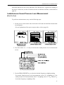
Using the Menu Screens
The NA-27 has four types of menu screens, namely SETUP, MEMORY, DISPLAY, and
I/O. Basic operation principles are the same for all four screens.
The following example explains how to use the SETUP menu screen to set the Leq measurement time to 10 minutes and the time constant for the sub channel to "SLOW".
1. Press the SETUP key.
The SETUP menu screen appears.
2. Use the or key to move the cursor to the "Leq Time" item.
3. The parameter indication shows "1 S" (current setting is "1 second").
The underline indicates where a change is possible.
4. Use the INC and DEC keys to set the value to "10".
With each push of the INC key, the value increases by 1. With each push of the
DEC key, the value decreases by 1. Holding a key down causes the values to change
continuously.
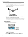
5. Use the key to move the underline to "S".
6. Use the INC and DEC keys to change "S" to "M".
7. Press the ENTER key. The parameter indication becomes "10M" (10 minutes), and
the cursor moves to the "Lx Time" item.
8. Use the key to move the cursor to the "SUB TIME CONST" item.
9. The parameter indication shows "FAST SLOW 35ms 10ms IMPULSE" (indicating
that the current setting is "FAST").
10. Use the or key to move the underline to "SLOW".
30
Preparations
11. Press the ENTER key.
The indication changes to "SLOW" and the cursor moves to the "Operation" item.
The time constant of the sub channel is now set to "SLOW".
12. Press the SETUP key to return to the original screen.
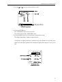
Menu screen conventions
z
z
Pressing the same menu screen key again returns to the measurement screen.
Pressing a different menu screen key allows switching to a different menu. Pressing the
new menu screen key again returns to the measurement screen.
31
Preparations
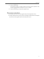
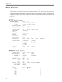
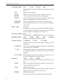
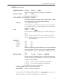
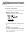
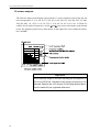
Menu Screens
The contents of all menu screens are reproduced below. The left side always shows the
setting item and the right side the parameter that can be changed. For more information on
changing settings, please refer to the section about setting measurement parameters on
page 36.
SETUP menu screen
MEASURE MODE
Leq Time
Lx Time
BACK ERASE TIME
Lmax / Lmin TYPE
:
:
:
:
:
LEQ
1 to 99S
10 to 99S
0 to 5s
AP
Lx
1 to 99M 1 to 99H
1 to 99M 1 to 99H
TRIGGER MODE
TRG LEVEL
SLOPE
TRG TIME
PERIOD
DELAY TIME
Sub Frq. Weight
Sub Time Const
:
:
:
:
:
:
:
:
OFF
LEVEL
10 to 140 dB
+
00:00 to 23:59
0 to 24 H
0 to 10 s
FLAT
A
FAST
SLOW
Condition Memory
: [0: DEFAULT]
[1: P_ON]
[2: USER]
[3: USER]
[4: USER]
[5: USER]
Operation
: LOAD
SAVE
ERASE
AUTO 2
MANU
EXEC
GROUP
10 to 990 ms
BAND
EXTRN
TIME
C
35ms
10ms
IMPULSE
MEMORY menu screen
MEMORY BLOCK
BLOCK CLEAR
AUTO STORE TYPE
PERIOD
NUM
PROTECT AUTO1
AUTO2
MANU
RECALL CALC
START ADDR
END ADDR
Directory
[ AU 1:
[ AU 2:
[ 001:
[ 002:
[ 003:
[ 004:
32
:
:
:
:
:
:
:
:
:
:
:
AUTO 1
OFF
SINGLE
1 to 10 ms
FREE
OFF
OFF
OFF
OFF
00001 to
00001 to
UP
ON
ON
ON
P_AVE
P_SUM
REVERB
DOWN
]
]
]
]
]
]
Preparations
DISPLAY menu screen
MAIN ADD DISP
: OFF
Lmax / Lmin
SUB DISP
ADD DISP
PEAK DISP
: OFF
: OFF
: OFF
ON
Lmax / Lmin
ON
Lx SELECT
:
:
:
:
:
:
:
:
:
:
OFF
OFF
OFF
OFF
OFF
OFF
OFF
OFF
OFF
OFF
ON
ON
ON
ON
ON
ON
ON
ON
ON
ON
PRINT MODE
SUC. PRINT BLK
START
END
INTERFACE PORT
:
:
:
:
:
SINGLE
AUTO1
00001 to
00001 to
SERIAL
SUCCESSIVE
AUTO2 MANU
BAUD RATE
SERIAL
OPTICAL
PRINTER
: 4800
: 57600
: 4800
9600
115200
9600
BEEP
: OFF
ON
REMOTE CONTROL : OFF
ON
L1
L5
L10
L50
L90
L95
L99
Lmax
Lmin
Leq
Ltm3 / Ltm5
I/O menu screen
DC OUT
DATE
TIME
VERSION
OPTICAL
19200
38400
: MAIN
SUB
: 00 to 99 / 00 to 12 / 00 to 31
: 00:00 to 23:59
: .
33
Preparations
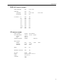
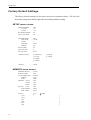
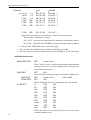
Factory Default Settings
The factory default settings for all menu screens are reproduced below. The left side
shows the setting item and the right side the default parameter setting.
SETUP menu screen
MEASURE MODE
Leq Time
Lx Time
BACK ERASE TIME
Lmax / Lmin TYPE
:
:
:
:
:
LEQ
1S
10 S
0S
AP
TRIGGER MODE
TRG LEVEL
SLOPE
TRG TIME
PERIOD
DELAY TIME
Sub Frq. Weight
Sub Time Const
:
:
:
:
:
:
:
:
OFF
60 dB
+
00:00
0H
0S
A
FAST
Condition Memory
: [0: DEFAULT]
[1: P_ON]
[2: USER]
[3: USER]
Operation
: LOAD
[4: USER]
[5: USER]
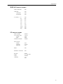
MEMORY menu screen
MEMORY BLOCK
BLOCK CLEAR
AUTO STORE TYPE
PERIOD
NUM
PROTECT AUTO1
AUTO2
MANU
RECALL CALC
START ADDR
END ADDR
Directory
[ AU 1:
[ AU 2:
[ 001:
[ 002:
[ 003:
[ 004:
34
:
:
:
:
:
:
:
:
:
:
:
AUTO 1
OFF
SINGLE
1 mS
FREE
OFF
OFF
OFF
OFF
00001
00070
UP
DOWN
]
]
]
]
]
]
Preparations
DISPLAY menu screen
MAIN ADD DISP
: OFF
SUB DISP
ADD DISP
PEAK DISP
: OFF
: OFF
: OFF
Lx SELECT
:
:
:
:
:
:
:
:
:
:
OFF
ON
ON
ON
ON
ON
OFF
OFF
OFF
OFF
PRINT MODE
SUC. PRINT BLK
START
END
INTERFACE PORT
:
:
:
:
:
SINGLE
AUTO 1
00001
00001
SERIAL
BAUD RATE
SERIAL
OPTICAL
PRINTER
: 9600
: 115200
: 9600
BEEP
: OFF
L1
L5
L10
L50
L90
L95
L99
Lmax
Lmin
Leq
I/O menu screen
REMOTE CONTROL : OFF
DC OUT
DATE
TIME
VERSION
: MAIN
: YY / MM / DD
: HH:MM
: .
35
Setting Measurement Parameters
Before carrying out a measurement or frequency analysis with this unit, the measurement parameters
must be set up as described below.
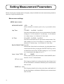
Menu screen settings
SETUP menu screen
MEASURE MODE:
LEQ
Lx
Selects whether to measure power (Leq) or percentile values
(Lx).
Leq Time:
1 to 99 S 1 to 99 M 1 to 99 H
Sets the measurement time for power measurements. Possible
settings are 1 to 99 seconds in 1 second steps, 1 to 99 minutes
in 1 minute steps, 1 to 99 hours in 1 hour steps.
Lx Time:
10 to 99 S 1 to 99 M 1 to 99 H
Sets the measurement time for percentile measurements. Possible settings are 10 to 99 seconds in 1 second steps, 1 to 99
minutes in 1 minute steps, 1 to 99 hours in 1 hour steps.
BACK ERASE TIME:0 to 5 S
Sets the time for the back-erase function, by which data from a
certain interval before pressing the PAUSE/CONT key can be
excluded from processing. Possible settings are 1 to 5 seconds
in 1 second steps. (See pages 66 to 67.)
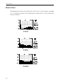
Lmax / Lmin TYPE: AP
BAND
Selects either all-pass (AP) maximum or band (BAND) maximum for Lmax/Lmin measurement.
AP max. mode
The frequency band levels at the point when the all-pass level
became maximum or minimum within the preset measurement
time are held.
BAND max. mode
The frequency band levels at the point when each band level
became maximum or minimum within the preset measurement
time are held.
36
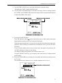
Setting Measurement Parameters
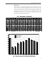
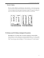
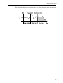
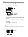
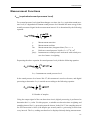
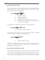
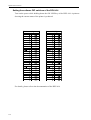
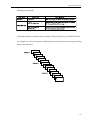
Explanation
This example uses 10 frequency analysis results for instantaneous levels.
Table 1 shows the values. The shaded data are the maximum levels for each
frequency band. The framed column shows the frequency band data at the
point when the all-pass level was maximum. In BAND max. mode, the
shaded data will be held. In AP max. mode, the framed data will be held.
Fig. 1 shows a comparison of the results.
37
Setting Measurement Parameters
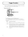
TRIGGER MODE:
OFF
LEVEL
EXTRN
TIME
Sets the trigger mode for starting the measurement. (See pages
68 to 73.)
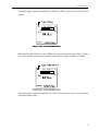
OFF:
Trigger mode is disabled.
LEVEL:
Trigger level can be set from 10 to 140 dB in 1 dB steps.
SLOPE:
- or + are used to set the slope for level triggering.
EXTRN:
Selects a CMOS logic-level signal to be used as trigger, supplied to the trigger input on the side of the unit.
TRG TIME:
Can be set from 00 h 00 m to 23 h 59 m in 1 minute steps.
PERIOD:
Sets the trigger repeat interval. Can be set from 0 to 24 hours in
1 hour steps.
DELAY TIME:
0 to 10 S
Sets the delay between the point when the START/STOP key
is pressed and the actual start of measurement. Can be set from
0 to 10 seconds in 1 second steps. (See page 74.)
SUB FRQ. WEIGHT:FLAT
A
C
Sets the frequency weighting characteristic for the sub channel.
SUB TIME CONST:
FAST
SLOW
35mS
10mS
IMPULSE
Sets the time weighting for the sub channel.
Condition Memory: 0: DEFAULT 1: P_ON
2-5: USER
Determines the way measurement parameter settings are stored
in memory.
0: DEFAULT Unit is reset to default measurement parameters when turned
off (except for SAVE, ERASE).
1: P_ON
Measurement parameters are stored when unit is turned off and
reestablished when next turned on (except for SAVE,
ERASE).
2 to 5: USER User-selectable measurement parameter settings. Use the
LEVEL UP/DOWN keys to select settings.
Operation:
LOAD
SAVE
ERASE
Controls the measurement parameter setting memory operation.
LOAD:
Load the specified measurement parameter settings. Previously established settings are lost.
SAVE:
(USER memory only)
Save the specified measurement parameter settings. The date
and time of the save operation are also stored.
ERASE:
(USER memory only)
Serves to erase specified measurement parameter settings.
38
Setting Measurement Parameters
MEMORY menu screen
MEMORY BLOCK:
AUTO1
AUTO2
MANU
Selects the memory block for storing or recalling data.
BLOCK CLEAR:
OFF
EXEC
Serves to erase stored data.
AUTO STORE TYPE: SINGLE GROUP
Determines whether auto store data are composed of a single
processing function or of all processing functions.
PERIOD:
1 to 10 ms, 10 to 990 ms
Determines the store interval for auto store. Can be set from 1
to 10 milliseconds in 1 ms steps and from 10 to 990 milliseconds in 10 ms steps.
NUM:
FREE
100 to
Sets the memory address number up to which storing is possible.
FREE: Memory upper limit is set as described on page 76.
100 to : Memory number is changed in steps of 100 with the
INC or DEC key.
PROTECT
AUTO1:
OFF
ON
AUTO2:
OFF
ON
MANU:
OFF
ON
When set to ON, the respective memory area is protected from
being overwritten. This serves to preserve measurement data.
When PROTECT is active, BLOCK CLEAR also has no effect.
RECALL CALC:
OFF
P_AVE
P_SUM
REVERB
Selects the type of calculation to be used for the recall mode.
The start address and end address are specified using START
ADDR and END ADDR.
P_AVE: Power average is calculated and displayed.
P_SUM: Power sum is calculated and displayed.
REVERB: Reverb time is displayed.
START ADDR: 00001 to Analysis start address
END ADDR:
00001 to Analysis end address
To set the START ADDR and END ADDR, use the and keys to move the
underline and then use the INC and DEC keys to set the value.
39
Setting Measurement Parameters
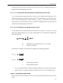
Directory
UP
96 / 05 / 02
96 / 05 / 04
96 / 05 / 10
96 / 05 / 10
96 / 05 / 12
96 / 05 / 3
DOWN
z [ AU 1: 1 / 1
12:34:56 ]
[ AU 2: 1 / 3
11:22:33 ]
[ 001: 1 / 3
10:10:10 ]
[ 002: SPL
15:15:15 ]
[ 003: SPL
17:17:15 ]
[ 004: SPL
19:19:15 ]
:
:
[ 200: SPL
96 / 05 / 25
15:15:15 ]
Indicates the type and store date and time of data in the mass memory.
The date/time is indicated as follows.
AU1, AU2: Auto store start date/time/The date/time is indicated as follows.
001 to 200: Date/time when STORE key was pressed for the respective address.
1. Use the LEVEL UP/DOWN keys to scroll the display.
2. The currently selected data block is marked with a black circle (z).
3. Move the cursor to the desired block and press the ENTER key to select the block.
DISPLAY menu screen
MAIN ADD DISP:
SUB DISP:
ADD DISP:
PEAK DISP:
Lx SELECT
40
OFF
Lmax / Lmin
When "Lmax / Lmin" is selected, the maximum and minimum
sound pressure level is always displayed in sound pressure
level measurement mode.
OFF
ON
Set to ON when wishing to display sub channel readings also.
OFF
Lmax / Lmin
Ltm3 / Ltm5
OFF
ON
Selects additional items to be displayed for the sub channel.
L1:
OFF
ON
L5:
OFF
ON
L10:
OFF
ON
L50:
OFF
ON
L90:
OFF
ON
L95:
OFF
ON
L99:
OFF
ON
Lmax:
OFF
ON
Lmin:
OFF
ON
Leq:
OFF
ON
Selects the items for Lx processing. Up to five items can be
selected simultaneously.
Setting Measurement Parameters
I/O menu screen
PRINT MODE:
SINGLE
SUCCESSIVE
Determines whether the printer (DPU-414, CP-10, CP-11)
prints only one sheet or operates continuously. The "SUCCESSIVE" setting is valid only in recall mode.
SUC. PRINT BLK: AUTO1
AUTO2
MANU
Specifies the memory block for successive printing.
START:
00001 to
END:
00001 to
Specifies the start address and end address of the memory
block specified for printing.
INTERFACE PORT: SERIAL
OPTICAL
Selects either the serial port or the infrared optical port for I/O
communication.
BAUD RATE
SERIAL:
4800
9600
19200
38400
OPTICAL:
57600
115200
PRINTER:
4800
9600
Sets the baud rate for the respective interface.
BEEP:
OFF
ON
Determines whether a beep tone is produced at the end of measurement and at other times.
REMOTE CONTROL: OFF
ON
When wishing to use the supplied remote control (NA-27RC1),
this item must be set to "ON".
DC OUT:
MAIN
SUB
Specifies which channel signal is supplied at the DC OUT output on the side of the unit.
DATE:
/
/
TIME:
:
These items allow the user to specify the date and time. While
the menu is displayed, the time indication does not advance.
VERSION:
.
41
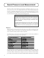
Sound Pressure Level Measurement
The NA-27 offers various kinds of measurements: instantaneous value (Lp, Lmax, Lmin,
Lpeak), power (Leq, LE, Ltm3, Ltm5), and percentile value (Lx). The maximum sound pressure
level (Lmax), minimum sound pressure level (Lmin), and waveform peak hold (Lpeak) refer
to the instantaneous level within the measurement time. Except for the instantaneous level
(Lp), the measurement applies to the preset measurement time.
Note
If measurement settings such as level range or frequency
weighting were changed during pause in instantaneous
value mode, the new settings will apply immediately when
pause is released.
If measurement settings such as level range or frequency
weighting were changed after processing, the new settings
will be effective only when processing the next measurement.
Power-on
When the power switch on the side of the unit is set to ON, the indication "Now
selftesting!!" appears on the display. After initialization and self-test are completed (between 10 and 20 seconds), the unit is ready for operation.
If a backup battery is inserted, the unit will in principle be set to the same condition as
before, except for the items shown in the table below.
If no backup battery is inserted, the indication "Backup Battery Empty!!" appears after
turning on the power. Insert a backup battery as described on page 16. When wishing to
use the unit without a backup battery, simply press any key to make the indication disappear. In this case, the memory store function and date and time functions are not available.
42
Sound Pressure Level Measurement
If the date and time are not set, the indication "RTC Read Error!!" appears after turning on
the power. In this case, use the I/O menu screen to set the date and time, as described on
page 24.
Instantaneous Sound Pressure Level Measurement
(LA, LC, Lp)
To perform a measurement, carry out the following steps.
1. Set the power switch on the side of the unit to ON and wait until the measurement
screen appears.
(For an explanation of the power-on procedure, refer to page 42.)
2. Press the SLM / 1/1 / 1/3 key to activate the sound pressure level measurement
screen.
3. Use the FREQ WEIGHT key to select the desired frequency weighting setting.
For normal sound pressure level measurements, select "A" weighting (LA). For
sound pressure level measurements with "C" weighting, select "C" (LC). When "Lp"
is selected, frequency weighting is flat.
43
Sound Pressure Level Measurement
4. Use the TIME CONST key to select the desired time constant setting.
Normally, the "FAST" setting should be used.
5. Use the LEVEL UP/DOWN keys to select the level range. Choose a setting in which
the "OVER" and "UNDER" indications do not appear (the bar graph should register
to about the middle of the range).
6. The level reading shown on the display corresponds to the current noise level (sound
pressure level). The reading is updated once every second.
The PAUSE/CONT key can be used to pause the measurement, i.e. to prevent the
level reading and bar graph indication from being updated. Pressing the key again
resumes the measurement.
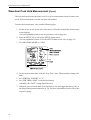
Using the sub channel
To use the sub channel, carry out the following steps.
1. Press the DISPLAY key.
The DISPLAY menu screen appears.
2. Use the and keys to move the flashing cursor to the "SUB DISP" item.
44
Sound Pressure Level Measurement
3. Use the
and
keys to set the parameter to ON.
4. Press the ENTER key.
The "SUB DISP" item is now set to ON.
The cursor moves to the "ADD DISP" item.
5. Press the DISPLAY key to return to the measurement screen.
The display appearance changes as shown below.
If frequency weighting and time constant for the sub channel are set to the same
values as for the main channel, the sub channel display does appear, even if set to
ON.
45
Sound Pressure Level Measurement
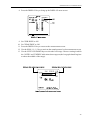
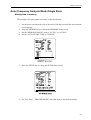
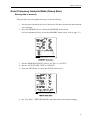
Maximum and Minimum Sound Pressure Level Measurement
(Lmax, Lmin)
The maximum and minimum sound pressure level for a given measurement interval can
be measured.
To make the measurement, carry out the following steps.
1. Set the power switch on the side of the unit to ON and wait until the measurement
screen appears.
(For an explanation of the power-on procedure, refer to page 42.)
2. Press the SETUP key to call up the SETUP menu screen.
(For an explanation of how to use the SETUP menu screen, refer to page 30.)
3. Set "MEASURE MODE" to "LEQ".
4. Set the measurement time with the "Leq Time" item. The maximum setting is 99
hours.
5. If desired, you can use the back-erase function (p. 66), the trigger function (p. 68), or
the delayed measurement function (p. 74). For more information, please refer to the
respective pages.
6. Press the SET UP key to return the measurement screen.
7. Use the SLM / 1/1 / 1/3 key to activate the sound pressure level measurement screen.
8. Use the FREQ WEIGHT key to select the desired frequency weighting setting.
For normal sound pressure level measurements, select "A" weighting (LA). For
sound pressure level measurements with "C" weighting, select "C" (LC). When "Lp"
is selected, frequency weighting is flat.
46
Sound Pressure Level Measurement
9. Use the TIME CONST key to select the desired time constant setting.
Normally, the "FAST" setting should be used.
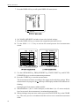
10. Use the LEVEL UP/DOWN keys to select the level range. Choose a setting in which
the "OVER" and "UNDER" indications do not appear (the bar graph should register
to about the middle of the range).
11. Press the START/STOP key.
The LED indicator and the mark on the display start to flash, and the maximum
and minimum sound pressure level measurement begins.
When the measurement time set in step 4 has elapsed, the measurement stops automatically. When wishing to terminate the measurement earlier, press the START/
STOP key.
If an overload condition has occurred at least once during the measurement, the
"OVER" indication is shown on the display.
The display reading corresponds to the sound pressure level.
Using the PAUSE/CONT key, you can pause and resume the level reading and bar
graph display.
12. Press the OPE MODE key to display the maximum and minimum sound pressure
level in turn.
The maximum level is shown as LAmax and the minimum level as LAmin.
47
Sound Pressure Level Measurement
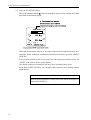
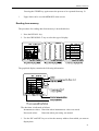
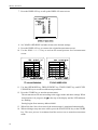
Waveform Peak Hold Measurement (Lpeak)
The waveform peak sound pressure level for a given measurement interval can be measured. This measurement is carried out in the sub channel.
To make the measurement, carry out the following steps.
1. Set the power switch on the side of the unit to ON and wait until the measurement
screen appears.
(For an explanation of the power-on procedure, refer to page 42.)
2. Press the SETUP key to call up the SETUP menu screen.
(For an explanation of how to use the SETUP menu screen, refer to page 30.)
3. Set "MEASURE MODE" to "LEQ".
4. Set the measurement time with the "Leq Time" item. The maximum setting is 99
hours.
5. Set "SUB FRQ. WEIGHT" to "C".
6. Set "SUB TIME CONST" to the desired setting.
Normally, the "FAST" setting should be used.
7. If desired, you can use the back-erase function (p. 66), the trigger function (p. 68), or
the delayed measurement function (p. 74). For more information, please refer to the
respective pages.
48
Sound Pressure Level Measurement
8. Press the DISPLAY key to bring up the DISPLAY menu screen.
9.
10.
11.
12.
13.
Set "SUB DISP" to ON.
Set "PEAK DISP" to ON.
Press the DISPLAY key to return to the measurement screen.
Use the SLM / 1/1 / 1/3 key to activate the sound pressure level measurement screen.
Use the LEVEL UP/DOWN keys to select the level range. Choose a setting in which
the "OVER" and "UNDER" indications do not appear (the bar graph should register
to about the middle of the range).
49
Sound Pressure Level Measurement
14. Press the START/STOP key.
The LED indicator and the mark on the display start to flash, and the waveform
peak hold measurement begins.
When the measurement time set in step 4 has elapsed, the measurement stops automatically. When wishing to terminate the measurement earlier, press the START/
STOP key.
If an overload condition has occurred at least once during the measurement, the
"OVER" indication is shown on the display.
The display reading corresponds to the noise level (sound pressure level).
Using the PAUSE/CONT key, you can pause and resume the level reading and bar
graph display.
Note
Peak hold measurement is being carried out while the display is
paused by PAUSE key.
50
Sound Pressure Level Measurement
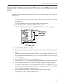
Equivalent Continuous Sound Pressure Level Measurement
(Leq)
To make the equivalent continuous sound pressure level measurement, carry out the following steps.
1. Set the power switch on the side of the unit to ON and wait until the measurement
screen appears.
(For an explanation of the power-on procedure, refer to page 42.)
2. Press the SETUP key to call up the SETUP menu screen.
(For an explanation of how to use the SETUP menu screen, refer to page 30.)
3. Set "MEASURE MODE" to "LEQ".
4. Set the measurement time with the "Leq Time" item. The maximum setting is 99
hours.
5. If desired, you can use the back-erase function (p. 66), the trigger function (p. 68), or
the delayed measurement function (p. 74). For more information, please refer to the
respective pages.
6. Press the SETUP key to return to the original screen.
7. Use the SLM / 1/1 / 1/3 key to activate the sound pressure level measurement screen.
8. Use the FREQ WEIGHT key to select the desired frequency weighting setting.
For normal sound pressure level measurements, select "A" weighting (LAeq). For
sound pressure level measurements with "C" weighting, select "C" (LCeq). When
"Lpeq" is selected, frequency weighting is flat.
9. Use the TIME CONST key to select the desired time constant setting.
Normally, the "FAST" setting should be used.
51
Sound Pressure Level Measurement
10. Use the LEVEL UP/DOWN keys to select the level range. Choose a setting in which
the "OVER" and "UNDER" indications do not appear (the bar graph should register
to about the middle of the range).
11. Press the START/STOP key.
The LED indicator and the mark on the display start to flash, and the equivalent
continuous sound pressure level measurement begins.
When the measurement time set in step 4 has elapsed, the measurement stops automatically. When wishing to terminate the measurement earlier, press the START/
STOP key.
If an overload condition has occurred at least once during the measurement, the
"OVER" indication is shown on the display.
The display reading corresponds to the sound pressure level.
Using the PAUSE/CONT key, you can pause and resume the level reading and bar
graph display.
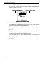
12. Press the OPE MODE key to display the equivalent continuous sound pressure
level (LAeq).
52
Sound Pressure Level Measurement
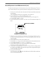
Sound Exposure Level Measurement (LAE)
To make the sound exposure level measurement, carry out the following steps. The procedure is almost identical to the equivalent continuous sound pressure level measurement.
1. Set the power switch on the side of the unit to ON and wait until the measurement
screen appears.
(For an explanation of the power-on procedure, refer to page 42.)
2. Press the SETUP key to call up the SETUP menu screen.
(For an explanation of how to use the SETUP menu screen, refer to page 30.)
3. Set "MEASURE MODE" to "LEQ".
4. Set the measurement time with the "Leq Time" item. The maximum setting is 99
hours.
5. If desired, you can use the back-erase function (p. 66), the trigger function (p. 68), or
the delayed measurement function (p. 74). For more information, please refer to the
respective pages.
6. Press the SETUP key to return to the original screen.
7. Use the SLM / 1/1 / 1/3 key to activate the sound pressure level measurement screen.
8. Use the FREQ WEIGHT key to select "A" weighting (LAE).
9. Use the TIME CONST key to select the desired time constant setting.
Normally, the "FAST" setting should be used.
10. Use the LEVEL UP/DOWN keys to select the level range. Choose a setting in which
the "OVER" and "UNDER" indications do not appear (the bar graph should register
to about the middle of the range).
11. Press the START/STOP key.
The LED indicator and the mark on the display start to flash, and the sound exposure level measurement begins.
53
Sound Pressure Level Measurement
When the measurement time set in step 4 has elapsed, the measurement stops automatically. When wishing to terminate the measurement earlier, press the START/
STOP key.
If an overload condition has occurred at least once during the measurement, the
"OVER" indication is shown on the display.
The display reading corresponds to the noise level (sound pressure level).
Using the PAUSE/CONT key, you can pause and resume the level reading and bar
graph display.
12. Press the OPE MODE key to display the sound exposure level (LAE).
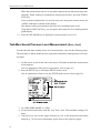
Takt-Max Sound Pressure Level Measurement (Ltm3, Ltm5)
To make the takt-max sound pressure level measurement, carry out the following steps.
The procedure is almost identical to the equivalent continuous sound pressure level measurement.
1. Set the power switch on the side of the unit to ON and wait until the measurement
screen appears.
(For an explanation of the power-on procedure, refer to page 42.)
2. Press the SETUP key to call up the SETUP menu screen.
(For an explanation of how to use the SETUP menu screen, refer to page 30.)
3. Set "MEASURE MODE" to "LEQ".
4. Set the measurement time with the "Leq Time" item. The maximum setting is 99
hours.
5. If desired, you can use the trigger function (p. 68), or the delayed measurement
function (p. 74). For more information, please refer to the respective pages.
54
Sound Pressure Level Measurement
6. Press the DISPLAY key to bring up the DISPLAY menu screen.
7. Set "SUB DISP" to ON and set "ADD DISP" to "Ltm3/Ltm5".
8. Press the SETUP key to call up the SETUP menu screen.
9. Set "SUB FRQ. WEIGHT" to "A" weighting and set "SUB TIME CONST" to
FAST.
10. Press the SETUP key to return to the original screen.
55
Sound Pressure Level Measurement
11. Use the SLM / 1/1 / 1/3 key to activate the sound pressure level measurement screen.
12. Use the LEVEL UP/DOWN keys to select the level range. Choose a setting in which
the "OVER" and "UNDER" indications do not appear (the bar graph should register
to about the middle of the range).
13. Press the START/STOP key.
The LED indicator and the mark on the display start to flash, and the takt-max
sound pressure level measurement begins.
When the measurement time set in step 4 has elapsed, the measurement stops automatically. When wishing to terminate the measurement earlier, press the START/
STOP key.
If an overload condition has occurred at least once during the measurement, the
"OVER" indication is shown on the display.
The display reading corresponds to the noise level (sound pressure level).
Using the PAUSE/CONT key, you can pause and resume the level reading and bar
graph display.
14. Press the OPE MODE key to display the takt-max sound pressure level (shown as
Lctm3 and Lctm5 under the sub channel indication).
56
Sound Pressure Level Measurement
Percentile Sound Pressure Level Measurement (Lx)
To make the percentile sound pressure level measurement, carry out the following steps.
The procedure is almost identical to the equivalent continuous sound pressure level measurement.
1. Set the power switch on the side of the unit to ON and wait until the measurement
screen appears.
(For an explanation of the power-on procedure, refer to page 42.)
2. Press the SETUP key to call up the SETUP menu screen.
(For an explanation of how to use the SETUP menu screen, refer to page 30.)
3. Set "MEASURE MODE" to "Lx".
4. Set the measurement time with the "Lx Time" item. The maximum setting is 99
hours.
5. If desired, you can use the trigger function (p. 68), or the delayed measurement
function (p. 74). For more information, please refer to the respective pages.
6. Press the DISPLAY key to bring up the DISPLAY menu screen.
57
Sound Pressure Level Measurement
7. Select up to five Lx settings out of L1 to Leq. If five settings are already selected and
you wish to use other settings, turn unused settings OFF first.
8. Press the DISPLAY key to return to the original screen.
9. Use the SLM / 1/1 / 1/3 key to activate the sound pressure level measurement screen.
The selected five percentile levels are shown.
10. Use the FREQ WEIGHT key to set frequency weighting to "A".
11. Use the TIME CONST key to select the desired time constant setting.
Normally, the "FAST" setting should be used.
12. Use the LEVEL UP/DOWN keys to select the level range. Choose a setting in which
the "OVER" and "UNDER" indications do not appear (the bar graph should register
to about the middle of the range).
13. Press the START/STOP key.
The LED indicator and the mark on the display start to flash, and the level measurement begins.
When the measurement time set in step 4 has elapsed, the measurement stops automatically. When wishing to terminate the measurement earlier, press the START/
STOP key.
If an overload condition has occurred at least once during the measurement, the
"OVER" indication is shown on the display.
The display reading shows the percentile sound pressure level for the selected settings.
Using the PAUSE/CONT key, you can pause and resume the level reading and bar
graph display.
14. Press the OPE MODE key to display the level.
58
1/1-Octave and 1/3-Octave Analysis
Note
If measurement settings such as level range or frequency
weighting were changed during pause in instantaneous
value mode, the new settings will apply immediately when
pause is released.
If measurement settings such as level range or frequency
weighting were changed after processing, the new settings
will be effective only when processing the next measurement.
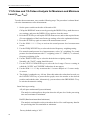
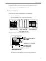
1/1-Octave and 1/3-Octave Analysis for Instantaneous Value
(LA, LC, Lp)
To make the measurement, carry out the following steps.
1. Set the power switch on the side of the unit to ON.
Call up the DISPLAY menu screen by pressing the
DISPLAY key, make the necessary settings, and
press the DISPLAY key again to close the menu.
2. Use the SLM / 1/1 / 1/3 key to activate the sound
pressure level measurement screen.
3. Use the FREQ WEIGHT key to select the desired
frequency weighting setting.
For normal sound pressure level measurements, select "A" weighting. For sound
pressure level measurements with "C" weighting, select "C". When "Lp" is selected,
frequency weighting is flat.
4. Use the TIME CONST key to select the desired time weighting setting.
Normally, the "FAST" setting should be used.
5. Use the LEVEL UP/DOWN keys to select the level range. Choose a setting in
which the "OVER" and "UNDER" indications do not appear.
6. Use the SLM / 1/1 / 1/3 key to activate the 1/1- octave analysis or 1/3-octave analysis screen.
7. The display is updated every 100 ms. Since this makes the values hard to read, use
the PAUSE/CONT key to pause the bar graph, move the marker to the desired
position, and read the value. Alternatively, you can also use the GRP/NUM/L-T key
to activate the numeric reading.
59
1/1-Octave and 1/3-Octave Analysis
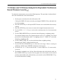
1/1-Octave and 1/3-Octave Analysis for Maximum and Minimum
Level (Lmax, Lmin)
To make the measurement, carry out the following steps. The procedure is almost identical to the instantaneous value measurement.
1. Set the power switch on the side of the unit to ON.
Call up the DISPLAY menu screen by pressing the DISPLAY key, make the necessary settings, and press the DISPLAY key again to close the menu.
2. Press the SETUP key to call up the SETUP menu screen, and set the required items.
(For an explanation of the Lmax/Lmin type setting, refer to the explanation below.)
3. Press the SETUP key again to return to the measurement screen.
4. Use the SLM / 1/1 / 1/3 key to activate the sound pressure level measurement
screen.
5. Use the FREQ WEIGHT key to select the desired frequency weighting setting.
For normal sound pressure level measurements, select "A" weighting. For sound
pressure level measurements with "C" weighting, select "C". When "Lp" is selected,
frequency weighting is flat.
6. Use the TIME CONST key to select the desired time weighting setting.
Normally, the "FAST" setting should be used.
7. Use the LEVEL UP/DOWN keys to select the level range. Choose a setting in
which the "OVER" and "UNDER" indications do not appear.
8. Use the SLM / 1/1 / 1/3 key to activate the 1/1-octave analysis or 1/3-octave analysis screen.
9. The display is updated every 100 ms. Since this makes the values hard to read, use
the PAUSE/CONT key to pause the bar graph, move the marker to the desired
position, and read the value. Alternatively, you can also use the GRP/NUM/L-T key
to activate the numeric reading.
Lmax/Lmin type setting
AP (All-pass maximum/all-pass minimum)
The analysis result applies to the point where the all-pass level in the processing
time was maximum or minimum.
BAND (Band maximum/band minimum)
The analysis result applies to the point where the level for each frequency band in
the processing time was maximum or minimum.
Factory default setting is "AP".
60
1/1-Octave and 1/3-Octave Analysis
1/1-Octave and 1/3-Octave Analysis for Equivalent Continuous
Sound Pressure Level (Leq)
To make the measurement, carry out the following steps. The procedure is almost identical to the instantaneous value measurement.
1. Set the power switch on the side of the unit to ON.
Call up the DISPLAY menu screen by pressing the DISPLAY key and make the
necessary settings.
2. Press the SETUP key to call up the SETUP menu screen and make the necessary
settings.
3. Press the SETUP key once more to return to the original measurement screen.
4. Use the SLM / 1/1 / 1/3 key to activate the sound pressure level measurement
screen.
5. Use the FREQ WEIGHT key to select the desired frequency weighting setting.
For normal sound pressure level measurements, select "A" weighting. For sound
pressure level measurements with "C" weighting, select "C". When "Lp" is selected,
frequency weighting is flat.
6. Use the TIME CONST key to select the desired time weighting setting.
Normally, the "FAST" setting should be used.
7. Use the LEVEL UP/DOWN keys to select the level range. Choose a setting in
which the "OVER" and "UNDER" indications do not appear.
8. Use the SLM / 1/1 / 1/3 key to activate the 1/1-octave analysis or 1/3-octave analysis screen.
9. The display is updated every 100 ms. Since this makes the values hard to read, use
the PAUSE/CONT key to pause the bar graph, move the marker to the desired
position, and read the value. Alternatively, you can also use the GRP/NUM/L-T key
to activate the numeric reading.
61
1/1-Octave and 1/3-Octave Analysis
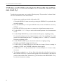
1/1-Octave and 1/3-Octave Analysis for Percentile Sound Pressure Level (Lx)
To make the measurement, carry out the following steps. The procedure is almost identical to the instantaneous value measurement.
1. Set the power switch on the side of the unit to ON.
Call up the DISPLAY menu screen by pressing the DISPLAY key and make the
necessary settings.
2. Press the SETUP key to call up the SETUP menu screen and make the necessary
settings.
3. Press the SETUP key once more to return to the original measurement screen.
4. Use the SLM / 1/1 / 1/3 key to activate the sound pressure level measurement
screen.
5. Use the FREQ WEIGHT key to select the desired frequency weighting setting.
For normal sound pressure level measurements, select "A" weighting. For sound
pressure level measurements with "C" weighting, select "C". When "Lp" is selected,
frequency weighting is flat.
6. Use the TIME CONST key to select the desired time weighting setting.
Normally, the "FAST" setting should be used.
7. Use the LEVEL UP/DOWN keys to select the level range. Choose a setting in
which the "OVER" and "UNDER" indications do not appear.
8. Use the SLM / 1/1 / 1/3 key to activate the 1/1-octave analysis or 1/3-octave analysis screen.
9. The display is updated every 100 ms. Since this makes the values hard to read, use
the PAUSE/CONT key to pause the bar graph, move the marker to the desired
position, and read the value. Alternatively, you can also use the GRP/NUM/L-T key
to activate the numeric reading.
62
1/1-Octave and 1/3-Octave Analysis
Explanation of Analysis Screens
1/1-octave analysis
The staircase shape on the display represents the 1/1-octave analysis result. From left, the
bars correspond to 16, 31.5, 63, 125, 250, 500, 1 k, 2 k, 4 k, 8 kHz. To read the levels at
these frequencies, use the and keys to move the marker to the desired point. The
frequency and level are then shown on the right of the screen under the indication
"MARK".
Important
The frequency range of this unit including the microphone is
20 Hz to 12500 Hz. Outside of this range, precision is not
assured. Data for the 16 Hz range should therefore be used
only as a general reference.
63
1/1-Octave and 1/3-Octave Analysis
1/3-octave analysis
The staircase shape on the display represents the 1/3-octave analysis result. From left, the
bars correspond to 12.5, 16, 20, 25, 31.5, 40, 50, 63, 80, 100, 125, 160, 200, 250, 315, 400,
500, 630, 800, 1 k, 1.25 k, 1.6 k, 2 k, 2.5 k, 3.15 k, 4 k, 5 k, 6.3 k, 8 k, 10 k, 12.5 kHz. To
read the levels at these frequencies, use the and keys to move the marker to the desired
point. The frequency and level are then shown on the right of the screen under the indication "MARK".
Important
The frequency range of this unit including the microphone is
20 Hz to 12500 Hz. Outside of this range, precision is not
assured. Data for the 12.5 Hz and 16 Hz range should therefore be used only as a general reference.
64
1/1-Octave and 1/3-Octave Analysis
Numeric display
Because it will be difficult to read all numeric values from the 1/1-octave and 1/3-octave
screen, the numeric display function should be used for this purpose. Use the GRP/NUM/
L-T key to toggle between the graphical and numeric display. The numeric readings are
shown in list format with the frequency on the left and the level on the right.
1/1-Octave and 1/3-Octave Analysis Precaution
Simultaneous 1/1-octave and 1/3-octave analysis is not possible
If for example 1/1-octave analysis was carried out and the SLM / 1/1 / 1/3 key is then
pushed to switch to 1/3-octave display, the displayed data are invalid except for the Lp
value. The same applies when switching to 1/1-octave display after 1/3-octave analysis.
65
Data Exclusion (Back-Erase) Function
When a measurement is being carried out and data are being processed, the PAUSE/
CONT key can be used to suspend the measurement. Normally, data up to the point at
which the PAUSE/CONT key was pressed will be included in processing, but the data
exclusion function makes it possible to exclude (back erase) data from an interval of 1 to
5 seconds before the key was pressed.
To activate the back-erase function, carry out the following steps.
1. Press the SETUP key to call up the SETUP menu screen.
(For an explanation of how to use the SETUP menu screen, refer to page 30.)
2. Set the "BACK ERASE TIME" item to the desired value. The setting range is 0 to
5 seconds in 1 second steps.
3. Press the SETUP key once more to return to the original measurement screen.
Important
- The back-erase function is not available in statistical
modes and in Ltm3 or Ltm5 mode.
- The instantaneous value (Lp) display always shows the
value at the pause point.
66
Data Exclusion (Back-Erase) Function
When the PAUSE/CONT key is pressed during measurement, the pause mark appears, the
indication "BE" is shown on the top right of the display for about a second, and the data are
back-erased. The measurement time is also reduced by the number of seconds set for the
back-erase function.
If the back-erase interval is longer than the measurement time, the measurement time becomes "0".
67
Trigger Function
The NA-27 incorporates three kinds of trigger functions: level trigger, external trigger,
and time trigger. The trigger can also be disabled completely.
Trigger mode selection
1. Press the SETUP key to call up the SETUP menu screen.
(For an explanation of how to use the SETUP menu screen, refer to page 30.)
2. Set the "TRIGGER MODE" item as desired. There are four possible settings, as
listed below.
OFF:
Trigger function is disabled.
LEVEL: Measurement starts when preset level conditions are met (see page
70).
EXTRN: An external CMOS logic-level signal (0 to 5 V) supplied to the trigger
input on the side of the NA-27 serves to trigger the measurement,
using the falling edge of the signal. The external trigger is also activated
when the terminals of the trigger input are shorted (see page 71).
TIME:
Measurement starts at a preset time and is repeated at preset intervals
(see page 73).
68
Trigger Function
When the trigger function is enabled, the indication "TRG" appears in the top left of the
display.
When the START/STOP key or the STORE key is pressed, the indication "TRG" is shown
in reverse, and the unit goes into standby mode until the trigger condition is fulfilled.
When the trigger condition is fulfilled, the "TRG" indication goes from reverse to normal,
and measurement starts.
69
Trigger Function
Level trigger
Level setting range:
Slope:
10 to 140 dB in 1 dB steps
+/-
1. Set the trigger level.
2. Set the slope.
When set to (+), the measurement starts when the input signal exceeds the trigger
level.
When set to (-), the measurement starts when the input signal, after having risen
once above the trigger level, falls below the trigger level for the first time.
Note
If the trigger level is set to 30 dB or lower, background noise
may prevent correct trigger operation, except in special environments such as in an anechoic chamber.
70
Trigger Function
External trigger
The external trigger can either be a CMOS logic-level signal supplied to the trigger input
or it can be activated by shortening the trigger input terminals.
A. Using a CMOS logic-level signal
1. Set the power switch on the side of the unit to OFF and connect the trigger cable.
2. When the connection has been established, set the power switch to ON and use the
SETUP menu screen to select the setting "EXTRN" for the trigger function.
The trigger is activated at the falling edge of the logic-level signal.
Set the "High" level of the logic-level signal source to 5 V±5%.
71
Trigger Function
B. Shorting the trigger input
1. Set the power switch on the side of the unit to OFF and connect the trigger cable.
2. When the connection has been established, set the power switch to ON and use the
SETUP menu screen to select the setting "EXTRN" for the trigger function.
3. Use a 2.5 mm miniature phone plug and shielded cable, and configure the trigger
circuit as shown above.
4. When the relay contacts close, the trigger is activated and measurement starts.
Note
The shielded cable should be no more than 2.5 meters long.
The minimum interrupted current capacity of the contacts
should be 50 µA or less.
Do not connect the contacts to any other circuitry.
The circuit should be configured as a floating (ungrounded)
circuit.
72
Trigger Function
Time trigger
TIME TRG (Measurement start time):
PERIOD (Measurement repeat interval):
00 h 00 m to 23 h 59 m in 1 minute steps
0 h to 24 h in 1 hour steps
1. Set the measurement start time with the "TIME TRG" item.
2. Set the measurement repeat interval with the "PERIOD" item.
z
z
When PERIOD is set to "0 H", the measurement is performed only once at the
preset time.
When PERIOD is set to a value smaller or equal to the measurement time, trigger
events within the measurement time are disregarded.
An example for the time trigger operation is shown below.
Measurement start time: 1 h 30 m
Measurement is performed every 2 hours after that.
73
Delayed Measurement
The delayed measurement function allows the user to complete all preparations and perform the steps for measurement start, while having the actual measurement start only after
a preset delay time.
1. Press the SETUP key to call up the SETUP menu screen.
(For an explanation of how to use the SETUP menu screen, refer to page 30.)
2. Set the "DELAY TIME" item as desired. The setting range is 0 to 10 seconds, in
1 second steps.
74
Delayed Measurement
If the trigger function is used concurrently, the delay time starts at the trigger point.
75
Memory Functions
The NA-27 incorporates a memory that allows manual and automatic storing of measurement data ("mass memory") and a separate memory for measurement parameter settings
("condition memory"). Stored measurement results can be displayed by pressing the RECALL key. To protect stored data, the mass memory can be set to read-only.
To use the memory, the backup battery must be inserted (see page 16).
MANU (manual store)
Measured instantaneous value data and processing results can be stored manually by
the operator. When the STORE key is pressed, measurement data, all processing results, measurement parameter settings, and measurement date and time are stored in
the currently selected address.
Up to 200 data sets can be stored in this way.
Note
If after completion of a measurement the measurement parameters (such as frequency weighting, time constant, level
up/down) are changed before pressing the STORE key,
there will be a mismatch between stored data and stored
measurement parameter settings.
AUTO (automatic store)
There are two identical memory blocks (AUTO1, AUTO2) for automatic storing of
data.
It is possible to automatically store either only the currently displayed measurement
result (single store) or to simultaneously store all processing results (group store), either at specified store time intervals or at the measurement time intervals.
Single store
10000 data/block:
4000 data/block:
2000 data/block:
Lp store interval:
76
(sound pressure level mode)
(1/1-octave analysis mode)
(1/3-octave analysis mode)
1 to 990 ms in 1 ms steps
Memory Functions
Group store
200 data
Store interval:
measurement time interval
The memory upper limit can be set with the "NUM" item on the MEMORY menu screen,
as described on page 39.
77
Memory Functions
Manual (Sound Pressure Level Mode)
Storing data in memory
At the point where the STORE key is pressed, the current instantaneous value and the
various processing results are stored in memory. The procedure is as described below.
1. Set the power switch on the side of the unit to ON and wait until the measurement
screen appears.
2. Press the MEMORY key to call up the MEMORY menu screen.
(For an explanation of how to use the MEMORY menu screen, refer to page 30.)
3. Set the "MEMORY BLOCK" item to "MANU".
4. Press the SETUP key to call up the SETUP menu screen.
5. Set "Leq Time", "TRIGGER MODE" and other items to the desired settings.
78
Memory Functions
6. Press the DISPLAY key to call up the DISPLAY menu screen.
7. Set "MAIN ADD DISP" and other items to the desired settings.
8. Press the DISPLAY key to return to the original measurement screen.
9. Use the SLM / 1/1 / 1/3 key to activate the sound pressure level measurement
screen.
10. Use the INC and DEC keys to select the memory address in which to store the
measurement data.
11. Press the START/STOP key to start the measurement. The measurement will start
according to the trigger mode and other settings. When measurement is in progress,
the at the top of the display and the LED indicator are flashing.
12. When the measurement is completed and the STORE key is pressed, one set of data
is stored in the selected address.
The address counter indication at the bottom right of the screen is shown in reverse,
and the counter is incremented by one.
13. By repeating the procedure from step 11, more data can be stored in memory.
79
Memory Functions
Reading from memory
The procedure for reading data from memory is described below.
1. Press the RECALL key.
2. Use the INC and DEC keys to select the memory address from which you want to
display data.
3. Use the OPE MODE key to select the processing type for display (LC, Lmax etc.)
The date/time shown on the display is the processing start date/time.
To check the date/time when the STORE key was pressed, use the "Directory" item
on the MEMORY menu screen.
An example for recalled data is shown below.
80
Memory Functions
Auto (Sound Pressure Level Mode) Single Store
Storing data in memory
1. Set the power switch on the side of the unit to ON and wait until the measurement
screen appears.
2. Press the MEMORY key to call up the MEMORY menu screen.
(For an explanation of how to use the MEMORY menu screen, refer to page 32.)
3. Set the "MEMORY BLOCK" item to "AUTO1" or "AUTO2 ".
4. Set the "AUTO STORE TYPE" to "SINGLE".
5. Press the SETUP key to call up the SETUP menu screen.
6. Set "Leq Time", "TRIGGER MODE" and other items to the desired settings.
81
Memory Functions
7. Press the DISPLAY key to call up the DISPLAY menu screen.
8. Set "MAIN ADD DISP" and other items to the desired settings.
9. Press the DISPLAY key to return to the original measurement screen.
10. Use the SLM / 1/1 / 1/3 key to activate the sound pressure level measurement
screen.
11. Use the OPE MODE key, FREQ WEIGHT key, TIME CONST key, and LEVEL
UP/DOWN keys to set the measurement parameters.
12. Press the STORE key to start the measurement.
The measurement will start according to the trigger mode and other settings. When
measurement is in progress, the at the top of the display and the LED indicator
are flashing.
13. When 10000 data * have been stored, the measurement is terminated automatically.
The LED indicator goes out.
14. When wishing to stop auto store earlier, press the START/STOP key or the STORE
key. The store process is terminated and the unit reverts to normal measurement
mode.
Pressing the STORE key again causes the process to be repeated from step 12.
* Upper limit can be set with MEMORY menu screen.
82
Memory Functions
Reading from memory
The procedure for reading data from memory is described below.
1. Press the RECALL key.
2. Use the INC and DEC keys to select the memory address from which you want to
display data.
The date/time is indicated as follows.
Instantaneous values:
Date/time when instantaneous value was stored.
Processed values:
Date/time when processing was started.
83
Memory Functions
Auto (Sound Pressure Level Mode) Group Store
Storing data in memory
The procedure for storing data in memory is described below.
1. Set the power switch on the side of the unit to ON and wait until the measurement
screen appears.
2. Press the MEMORY key to call up the MEMORY menu screen.
3. Set the "MEMORY BLOCK" item to "AUTO1" or "AUTO2".
4. Set the "AUTO STORE TYPE" to "GROUP".
5. Press the SETUP key to call up the SETUP menu screen.
6. Set "Leq Time", "TRIGGER MODE" and other items to the desired settings.
84
Memory Functions
7. Press the DISPLAY key to call up the DISPLAY menu screen.
8. Set "MAIN ADD DISP" and other items to the desired settings.
9. Press the DISPLAY key to return to the original measurement screen.
10. Use the SLM / 1/1 / 1/3 key to activate the sound pressure level measurement
screen.
11. Use the OPE MODE key, FREQ WEIGHT key, TIME CONST key, and LEVEL
UP/DOWN keys to set the measurement parameters.
12. Press the STORE key to start the measurement.
The measurement will start according to the trigger mode and other settings. When
measurement is in progress, the at the top of the display and the LED indicator are
flashing.
Storing begins from memory address 00001.
13. When 200 data * have been stored, the measurement is terminated automatically.
The LED indicator goes out.
14. When wishing to stop auto store earlier, press the START/STOP key or the STORE
key. The store process is terminated and the unit reverts to normal measurement
mode.
Pressing the STORE key again causes the process to be repeated from step 12.
* Upper limit can be set with MEMORY menu screen.
85
Memory Functions
Reading from memory
The procedure for reading data from memory is described below.
1. Press the RECALL key.
2. Use the INC and DEC keys to select the memory address from which you want to
display data.
3. Use the OPE MODE key to select the processing type for display (LC, Lmax etc.)
The date/time shown on the display is the processing start date/time.
86
Memory Functions
Manual (Frequency Analysis Mode)
Storing data in memory
At the point where the STORE key is pressed, the current instantaneous value and the
various processing results are stored in memory. The procedure is as described below.
1. Set the power switch on the side of the unit to ON
and wait until the measurement screen appears.
2. Press the MEMORY key to call up the MEMORY
menu screen.
3. Set the "MEMORY BLOCK" item to "MANU".
4. Press the SETUP key to call up the SETUP menu
screen.
5. Set "Leq Time", "TRIGGER MODE" and other
items to the desired settings.
6. Press the DISPLAY key to call up the DISPLAY
menu screen.
7. Set "MAIN ADD DISP" and other items to the
desired settings.
8. Press the DISPLAY key to return to the original
measurement screen.
9. Use the SLM / 1/1 1/3 key to activate the frequency analysis screen.
10. Use the INC and DEC keys to select the memory
address in which to store the measurement data.
11. Press the START/STOP key to start the measurement. The measurement will start according to the
trigger mode and other settings. When measurement is in progress, the at the top of the display
and the LED indicator are flashing.
12. When the measurement is completed and the
STORE key is pressed, one set of data is stored in
the selected address.
The address counter indication at the bottom right
of the screen is shown in reverse, and the counter
is incremented by one.
13. By repeating the procedure from setup 11, more
data can be stored in memory. Use the INC and DEC keys to select the memory
address in which to store the measurement data.
87
Memory Functions
Reading from memory
The procedure for reading data from memory is described below.
1. Press the RECALL key.
2. Use the INC and DEC keys to select the memory address from which you want to
display data.
3. Use the OPE MODE key to select the processing type for display (LC, Lmax etc.).
An example for recalled 1/3-octave analysis data is shown below.
The date/time shown on the display is the processing start date/time.
To check the date/time when the STORE key was pressed, use the "Directory" item
on the MEMORY menu screen.
4. When moving the cursor with the
at the right of the screen changes.
88
and
keys, the frequency and level displayed
Memory Functions
Auto (Frequency Analysis Mode) Single Store
Storing data in memory
The procedure for storing data in memory is described below.
1. Set the power switch on the side of the unit to ON and wait until the measurement
screen appears.
2. Press the MEMORY key to call up the MEMORY menu screen.
3. Set the "MEMORY BLOCK" item to "AUTO1" or "AUTO2".
4. Set the "AUTO STORE TYPE" to "SINGLE".
5. Press the SETUP key to call up the SETUP menu screen.
6. Set "Leq Time", "TRIGGER MODE" and other items to the desired settings.
89
Memory Functions
7. Press the DISPLAY key to call up the DISPLAY menu screen.
8. Set "MAIN ADD DISP" and other items to the desired settings.
9. Press the DISPLAY key to return to the original measurement screen.
10. Use the SLM / 1/1 / 1/3 key to activate the sound pressure level measurement
screen.
11. Use the OPE MODE key, FREQ WEIGHT key, TIME CONST key, and LEVEL
UP/DOWN keys to set the measurement parameters.
12. Press the STORE key to start the measurement.
The measurement will start according to the trigger mode and other settings. When
measurement is in progress, the at the top of the display and the LED indicator are
flashing.
Storing begins from memory address 00001.
13. When 4000 data * (for 1/1-octave analysis) or 2000 data * (for 1/3-octave analysis)
have been stored, the measurement is terminated automatically.
14. When wishing to stop auto store earlier, press the START/STOP key or the STORE
key. The store process is terminated and the unit reverts to normal measurement
mode.
90
Memory Functions
Pressing the STORE key again causes the process to be repeated from step 12.
*
Upper limit can be set with MEMORY menu screen.
Reading from memory
The procedure for reading data from memory is described below.
1. Press the RECALL key.
2. Use the GRP/NUM/L-T key to select the type of display.
The graphical display contains the following information.
The date/time is indicated as follows.
Instantaneous values: Date/time when instantaneous value was stored.
Processed values:
Date/time when processing was started.
1. Use the INC and DEC keys to select the memory address from which you want to
display data.
91
Memory Functions
2. When moving the cursor with the
at the right of the screen changes.
and
keys, the frequency and level displayed
The level-time display contains the following information.
1. Use the INC and DEC keys to select the memory address from which you want to
display data.
2. Use the LEVEL UP/DOWN ( LT / LT ) keys to select the display compression ratio.
Pressing the LT key widens the address range, and pressing the LT key
narrows it down.
3. Use the and keys to select the frequency band.
When the compression ratio is 1/2 or higher, data for two or more addresses are shown at
the cursor line. Address data are expressed by drawing a line from the highest to the lowest
level.
When several address data are combined, the cursor shows the lowest (first) address and
the highest level of the combined addresses.
An example for 1/1 and 1/5 compression is shown below.
92
Memory Functions
Auto (Frequency Analysis Mode) Group Store
Storing data in memory
The procedure for storing data in memory is described below.
1. Set the power switch on the side of the unit to ON and wait until the measurement
screen appears.
2. Press the MEMORY key to call up the MEMORY menu screen.
(For an explanation of how to use the MEMORY menu screen, refer to page 32.)
3. Set the "MEMORY BLOCK" item to "AUTO1" or "AUTO2".
4. Set the "AUTO STORE TYPE" to "GROUP".
5. Press the SETUP key to call up the SETUP menu screen.
6. Set "Leq Time", "TRIGGER MODE" and other items to the desired settings.
93
Memory Functions
7. Press the DISPLAY key to call up the DISPLAY menu screen.
8. Set "MAIN ADD DISP" and other items to the desired settings.
9. Press the DISPLAY key to return to the original measurement screen.
10. Use the SLM / 1/1 / 1/3 key to activate the sound pressure level measurement
screen.
11. Use the OPE MODE key, FREQ WEIGHT key, TIME CONST key, and LEVEL
UP/DOWN keys to set the measurement parameters.
12. Press the STORE key to start the measurement.
The measurement will start according to the trigger mode and other settings. When
measurement is in progress, the at the top of the display and the LED indicator
are flashing.
Storing begins from memory address 00001.
13. When 200 data * have been stored, the measurement is terminated automatically.
14. When wishing to stop auto store earlier, press the START/STOP key or the STORE
key. The store process is terminated and the unit reverts to normal measurement
mode.
94
Memory Functions
Pressing the STORE key again causes the process to be repeated from step 12.
* Upper limit can be set with MEMORY menu screen.
Reading from memory
The procedure for reading data from memory is described below.
1. Press the RECALL key.
2. Use the GRP/NUM/L-T key to select the type of display.
The graphical display contains the following information.
The date/time shown on the display is the processing start date/time.
95
Memory Functions
1. Use the INC and DEC keys to select the memory address from which you want to
display data.
2. Use the OPE MODE key to select the processing type for display (LC, Lmax etc.).
3. When moving the cursor with the and keys, the frequency and level displayed
at the right of the screen changes.
The level-time display contains the following information.
1. Use the INC and DEC keys to select the memory address from which you want to
display data.
2. Use the LEVEL UP/DOWN ( LT / LT ) keys to select the display compression ratio.
Pressing the LT key widens the address range, and pressing the LT key
narrows it down.
When the compression ratio is 1/2 or higher, data for two or more addresses are
shown at the cursor line. Address data are expressed by drawing a line from the
highest to the lowest level.
When several address data are combined, the cursor shows the lowest (first) address and the highest level of the combined addresses.
96
Memory Functions
An example for 1/1 and 1/5 compression is shown below.
3. Use the and keys to select the frequency band.
4. Use the OPE MODE key to select the type of processing.
97
Memory Functions
Erasing Data
All data stored in an address block can be erased as follows.
Take care not to accidentally erase data that you want to keep.
1. Press the MEMORY key to call up the MEMORY menu screen.
2. Select the memory block which you want to erase.
3. Set the "PROTECT" item for the memory block to OFF.
4. Move the cursor to the "BLOCK CLEAR" item.
5. Use the and keys to select EXEC.
6. Press the ENTER key to erase all data in the selected memory block.
98
Memory Functions
Recall Processing
Using the recall processing function, power average (P_AVE), power sum (P_SUM), and
reverb time (REVERB) can be calculated.
The following explanation is for power average (P_AVE), but the procedure for other
functions is identical.
1. Store data using the auto store function for frequency analysis in single (p. 89) or
group (p. 93) mode.
2. Press the MEMORY key to call up the MEMORY menu screen.
3. Move the cursor to the "RECALL CALC" item.
4. Set the item to "P_AVE".
5. Press the MEMORY key to return to the analysis screen.
99
Memory Functions
6. Use the INC and DEC keys to select the processing start address. (The left border of
the screen corresponds to the processing start address.)
7. Use the and keys to select the processing end address.
8. The bottom of the screen shows "P_AVE
. dB" (when power sum is selected:
"P_SUM
. dB").
The result for power average or power sum processing (for all frequency bands
together) is shown on the graphical screen or the numeric list display.
When reverberation processing is selected, the display shows "REVERB
. S".
In this mode, the analysis data in the graphical screen and numeric list display are
recalled data from the start address of the processing range. (The same applies when
recall processing is set to OFF.)
9. When the recall screen is terminated, processing is automatically set to OFF.
If the start address (START ADDR) and end address (END ADDR) were specified
in step 4 on the MEMORY menu screen, the cursor automatically is placed on the
processing end address during level-time recall display.
100
Remote Control (NA-27RC1)
The supplied infrared remote control (NA-27RC1) allows operating the sound level meter
from a distance of up to 3 meters. The top panel of the control has buttons for controlling
measurement progress and changing measurement parameter settings.
START STOP key
Serves to start and stop the measurement.
PAUSE CONT key
Serves to pause the measurement. When the back-erase
function is activated, data immediately preceding the
point when the key was pressed are excluded from processing.
LEVEL UP DOWN keys
Serve to select the level range.
FAST, SLOW, 10ms keys
Serve to select the time constant for the main channel.
Lp, Leq, LE, Lmax, Lmin keys
Serve to select the measurement result display type.
STORE key
Serves to store data in the internal memory of the NA-27.
The key also serves to terminate the store process.
A, C keys
Serve to select frequency weighting for the main channel.
A: "A" characteristics
C: "C" characteristics
PRINT key
Serves to print out the display contents of the NA-27 on a
connecting printer (DPU-414, CP-10, CP-11).
101
Remote Control
To use the remote control, insert two IEC R03 (size AAA) batteries in the battery compartment on the rear.
1. Push the cover of the battery compartment down in direction of the arrow mark and
slide it off.
2. Insert two IEC R03 (size AAA) batteries, taking care to establish correct polarity.
3. Replace the cover of the battery compartment.
Important
Take care not to reverse the (+) and (-) polarity when inserting a battery.
Always use two identical batteries, and replace batteries
only as a set. Mixing battery types or old and new batteries
can lead to damage.
Remove the batteries from the unit if it is not to be used for a
week or longer.
102
Technical Notes
Microphone
Measurements of sound pressure level can be carried out with a variety of microphone
types. The precision integral sound pressure level meter NA-27 employs the prepolarized
condenser microphone UC-53A that is compact and delivers stable and reliable response.
Construction and Operation Principle
As shown in the drawing below, a prepolarized condenser microphone consists of four
main parts: diaphragm, backplate, insulator, and housing. The surface of the backplate is
covered by a film holding an electrical charge. When sound pressure is applied to the
diaphragm, the distance between the diaphragm and the backplate changes, thereby altering the capacitance. Using a load resistor, this change can be turned into a voltage change.
The frequency response as well as the temperature and humidity characteristics of an
prepolarized microphone depend considerably on the type and properties of the materials
used. The frequency range is determined by the resonance frequency of the diaphragm
assembly.
103
Technical Notes
Frequency Response
The frequency response of a sound field microphone is expressed as the frequency response in the reference direction of incidence (0º). The diagram below shows an example
for the frequency response of the microphone UC-53A.
104
Technical Notes
Directional characteristics
The directional characteristics of a microphone is a measure of its differing sensitivity for
sound waves arriving from various angles. Since the prepolarized condenser microphone
used in the NA-27 is a pressure-sensitive type, it should be equally sensitive in all directions. However, refraction and cavity effects cause a certain microphone directional characteristics at high frequencies. The diagram below shows the directional characteristics of
the microphone UC-53A.
105
Technical Notes
Thermal Characteristics
The thermal characteristics of a microphone indicate how sensitivity changes at various
temperatures. This is influenced by the choice of materials and the design of the microphone. Normally, materials with a linear expansion coefficient are used. The diagrams
below show the thermal characteristics of the microphone UC-53A.
Humidity Characteristics
The humidity characteristics of a microphone indicate how sensitivity changes at various
humidity levels. The diagrams below show the microphone UC-53A.
106
Technical Notes
Microphone (UC-53A) Specifications
Nominal diameter:
1/2 inch
Sensitivity:
-28 dB (0 dB = 1 V/Pa at 1000 Hz)
Frequency response:
10 to 20000 Hz
Capacitance:
12 pF
Diaphragm type:
Titan alloy film
Temperature coefficient:
+0.005 dB/ºC (at 250 Hz)
Humidity-dependent sensitivity change:
0.1 dB or less (at 250 Hz, RH below 95%, no condensation)
Dimensions:
13.2 dia. × 12.9 mm
107
Technical Notes
Preamplifier
Preamplifier Requirement
Since the condenser microphone is a small-capacity transducer, it has high impedance,
especially at low frequencies. Therefore a very high load resistance is required to ensure
uniform response extending to the low frequency range. The relationship between the
microphone capacitance and the low-range cutoff frequency can be expressed as follows.
F f0:
Zin:
Cm:
Low-range cutoff frequency (Hz)
Preamplifier input impedance (Ω)
Capacitance of condenser microphone (F)
If the output of the microphone were directly routed through a long shielded cable, the
capacitance between the cable conductors would cause a sharp drop in sensitivity, as is
evident from the following equation.
M0:
Ms:
Cc:
Output voltage into directly connected shielded cable (V)
Output voltage in microphone open condition (V)
Cable capacitance of shielded cable (F)
For the above reasons, a preamplifier is connected directly after the microphone, to provide a low-impedance output signal.
Preamplifier Specifications
Input impedance:
Output impedance:
Maximum output current:
108
3 GΩ
Less than 300 Ω
2 mA
Technical Notes
Microphone Extension Cable (EC-04 series)
To reduce measurement deviations due to refraction effects and the acoustic influence of
the operator, the microphone/preamplifier assembly can be detached from the main unit
and connected via an extension cable.
Optional cables are listed in the table below.
1. Set the power switch to OFF.
2. Loosen the preamplifier fastening screw and separate the microphone/preamplifier
assembly from the main unit.
3. Connect the extension cable to the microphone/preamplifier assembly and to the
main unit.
Important
Never attempt to disassemble or separate the microphone
and preamplifier since this can lead to damage.
Important
With long extension cables, the cable capacitance restricts
the upper measurement frequency and measurement level.
For details, please refer to page 111.
109
Technical Notes
4. When mounting the microphone/preamplifier on a tripod, first fasten the microphone holder (supplied with the extension cable) to the tripod. Then insert the extension cable connector into the microphone holder.
110
Technical Notes
When the output of the microphone/preamplifier is routed through an extension cable,
certain limitations regarding measurable sound pressure level and frequency range will
apply. This is due to the influence of the cable capacitance. The longer the cable, the lower
the measurable sound pressure level and the lower the frequency limit. The diagram below
shows the relationship between cable length, measurable sound pressure level, and frequency.
If for example a sound pressure level of 120 dB is to be measured up to 3 kHz, an extension cable length of up to 100 meters can be used.
111
Technical Notes
Amplifier Circuit Configuration
The amplifier circuit configuration and level diagram of the NA-27 are shown below. The
degree of attenuation and degree of amplification depends on the level range setting.
112
Technical Notes
Frequency Weighting Network
The NA-27 provides a choice between "A", "C" and "Flat" frequency weighting. The electrical characteristics of the weighting circuitry are as shown below.
The volume impression (loudness) of a sound depends not only on the sound pressure
level, but also on the frequency. At high or low frequencies, a sound is felt to be less loud
than a sound of equal level in the midrange. The "A" weighting curve compensates for this
effect and produces measurement results which are close to the actual impression of loudness. For this reason, this type of frequency weighting is widely used for purposes such as
sound pressure level evaluation.
With the "Flat" characteristic, frequency response is linear, which is suitable for straight
sound pressure level measurements and for using the sound pressure level meter output
for frequency analysis.
The "C" weighting curve produces almost flat response, but with a rolloff below 31.5 Hz
and above 8 kHz. This is suitable for sound pressure level measurements in situations with
unwanted low-frequency or high-frequency components.
113
Technical Notes
RMS Detection Circuit
The sound pressure level meter uses rms detection. The effective value E (rms) is defined
by the following equation.
The voltage e which changes over time is raised to the power of 2, and integration for the
time interval T is performed. The result is divided by T and the square root is extracted.
The circuit configuration for performing the above mathematical operation looks as follows.
The NA-27 performs all above processing functions in the digital domain.
For measurement and evaluation of the rms detection circuit, a signal with known crest
factor is used. The crest factor is defined as crest value divided by effective value. If the
signal type is known, the crest factor can be calculated precisely.
The rms detection error of the NA-27 is about ± 0.2 dB for an input signal with a crest
factor of 3.
During sound pressure level measurements, the level often fluctuates drastically, which
would make it difficult to evaluate readings if some kind of averaging is not applied.
Sound pressure level meters therefore provide the capability for index weighting (index
averaging) using the rms circuit. The parameters of this weighting process are called the
dynamic characteristics, determined by the time weighting (see page 116).
Sound pressure level meters usually have a "Fast" and "Slow" setting for the time weighting. The time range that is considered for averaging is narrow in the "Fast" setting and
wide in the "Slow" setting. In the "Fast" setting, the instantaneous level has a larger bearing on the displayed value than in the "Slow" setting. From the point of view of the measurement objective, the "Fast" setting is more suitable to situations with swiftly changing
sound pressure level, whereas the "Slow" setting yields a more broadly averaged picture.
The "Fast" setting is more commonly used, and sound pressure level or sound pressure
level values given without other indication are usually made with "Fast" characteristics.
114
Technical Notes
The "Slow" time weighting setting is suitable for measuring the average of noise with
fairly constant levels. Aircraft noise and high-speed train noise is usually transient noise
with high fluctuation, but here the "Slow" setting is used to determine the maximum level
for each noise event.
The "10 ms" setting of the NA-27 results in a very short time weighting, enabling the
meter to closely follow noise fluctuations.
The "Imp (Impulse)" setting enables the meter to track noise bursts of very short duration.
In the "Peak (Peak Hold)" condition, no averaging is carried out, and the peak value of the
frequency-weighted sound pressure waveform is displayed.
115
Technical Notes
Time weightings and time constant
The time weighting circuit of the sound pressure level meter performs index averaging on
the square of the sound pressure signal. The equivalent circuit is shown at right. τ is the
time weighting, which equals CR.
J
The response of the index averaging circuit to a single burst signal is shown below.
J
J
116
Technical Notes
Measurement Functions
L Aeq (equivalent sound pressure level)
For a sound pressure level signal that changes over time, the LAeq (equivalent sound pressure level) is a hypothetical constant sound pressure level that has the same energy as the
actually measured signal in the measurement interval. It is determined by the following
equation.
t 1:
t 2:
Tm:
p0:
pA(t):
Measurement start time
Measurement end time
Measurement time (integrated time) Tm = t2 - t1
Reference sound pressure 20 µPa (2 × 10⁻⁵ N / m2)
Instantaneous sound pressure measured with sound pressure level meter A weighting
Expressing the above equation for sound pressure level yields the following equation.
LA(t) : Instantaneous sound pressure level
In the sound pressure level meter NA-27, this statement is used as reference, and digital
processing to determine LAeq is carried out according to the following equation.
N: Number of samples
Using the output signal of the rms detection circuit, digital processing is performed to
determine the LAeq value. For this purpose, a suitable rms detection time weighting and
sampling interval for LAeq processing must be chosen. In the NA-27, the sampling interval
for A/D conversion is 10 ms (100 samples per second), and LAeq processing is carried out
every interval. The LAeq reading can therefore be displayed already during measurement.
117
Technical Notes
L AE (sound exposure level)
The LAE (sound exposure level) is a hypothetical constant 1-second sound pressure level
having the same energy as a single-event sound pressure level measured with A weighting. It is determined by the following equation.
t 1:
t 2:
T0:
p0:
pA(t):
Measurement start time
Measurement end time
Reference time (1 second)
Reference sound pressure 20 µPa (2 × 10⁻⁵ N / m2)
Instantaneous sound pressure measured with sound pressure level meter A weighting
Expressing the above equation for sound pressure level yields the following.
LA(t):
Instantaneous sound pressure level
In the sound pressure level meter NA-27, this statement is used as reference, and digital
processing is carried out according to the following equation.
N0:
Number of samples per second
In the NA-27, the sampling interval for A/D conversion is 10 ms (100 samples per second), and LAE processing is carried out every interval. The LAE reading can therefore be
displayed already during measurement.
L x (percentile sound pressure level)
The Lx (percentile sound pressure level) is the sound pressure level which was exceeded
for x percent of the measurement time. The NA-27 allows the user to select five values for
x (from 1 to 99, in 1-percent steps), and calculates the time percentile level for these five
values simultaneously. The sampling interval for Lx processing is 100 ms (10 samples per
118
Technical Notes
second), and Lx processing is carried out every interval. The Lx reading can therefore be
displayed already during measurement.
L max , L min (maximum and minimum sound pressure level)
Lmax is the maximum sound pressure level and Lmin the minimum sound pressure level
encountered during a measurement. In the NA-27, the sampling interval for A/D conversion is 10 ms (100 samples per second), and the Lmax and Lmin values since the start of the
measurement are stored. Therefore the Lmax and Lmin readings up to the current point can
be displayed already during measurement.
L tm3 , L tm5 (Takt-max sound pressure level)
For the duration of the measurement, the maximum level within a 3-second or 5-second
interval is sampled and the power average is determined. Ltm is calculated according to the
following equation.
Lm:
N:
Maximum level within interval (3 or 5 seconds)
Number of samples
The number of samples is determined according to the following equation.
For Ltm3:
For Ltm5:
t 1:
t 2:
Measurement start time
Measurement end time
* Ltm is specified by DIN as "Taktmaximalpegel Mittelwert", and its meaning in English is "Power averaged maximum sound pressure level in a measuring period".
Lpeak (waveform peak hold)
The waveform peak sound pressure level for a given measurement interval can be measured.
119
Technical Notes
Noise Floor
The diagrams below show the residual noise of the NA-27, in the frequency weighting
"A", "C" and "Flat" positions. The measurement was made with a 1/3 octave filter and a
frequency analyzer.
120
Technical Notes
Background Noise
When measuring a certain sound in a certain location, all other sounds present at that
location except the measurement target sound are background noise (also called ambient
noise or dark noise). Since the sound pressure level meter will display the combination of
target sound and background noise, the amount of background noise must be taken into
consideration when determining the level of the target sound.
If the difference between the meter reading in absence of the target sound and the reading
with the target sound is more than 10 dB, the influence of background noise is small and
may be disregarded. If the difference is less than 10 dB, the values shown in the table
below may be used for compensation, to estimate the level of the target sound.
If for example the measured sound pressure level when operating a machine is 70 dB, and
the background sound pressure level when the machine is not operating is 63 dB, the
compensation value for the difference of 7 dB is -1 dB. Therefore the sound pressure level
of the machine can be taken to be 70 dB + (-1 dB) = 69 dB.
The above principle for compensating the influence of the background noise assumes that
both the background noise and the target sound are approximately constant. If the background noise fluctuates, and especially if it is close in level to the target sound, compensation is difficult and will often be meaningless.
121
Technical Notes
Windscreen (WS-02)
During outdoor measurements or measurement of ventilation devices, wind noise can falsify measurement results. To counter such problems, the supplied windscreen WS-02
should be mounted on the microphone. The characteristics of the WS-02 are shown below. The attenuation of wind noise produced by the windscreen is about 25 dB for sound
pressure level (A weighting) and 15 dB for sound pressure level.
The influence of the windscreen WS-02 on the acoustic performance of the microphone is
within ± 1.0 dB up to 12.5 kHz, as shown in the diagram on the next page.
122
Technical Notes
123
Technical Notes
124
Technical Notes
I/O Connector
The I/O connector on the NA-27 serves for input of control signals and input/output of
data. It has the following functions.
z
Measurement data output to printer DPU-414, CP-10, CP-11
(with printer cable of 25 pins, male, straight type and communication cable for
IBM/AT or compatible computers)
z
Communication with a computer (RS-232C interface)
(with interface cable of 9 pins, straight type, communication cable for IBM/AT or
compatible computers)
125
Technical Notes
1/1-Octave Filter Characteristics
The characteristics of the 1/1-octave filter in the NA-27 correspond to the JIS C 15131983 Type II, ANSI S1.11 Type 1D, and IEC 1260 1995 Class 1 specifications.
The graph below shows the allowable attenuation tolerance according to JIS and the actual
characteristics of the 1/1-octave filter in the NA-27.
126
Technical Notes
1/3-Octave Filter Characteristics
The characteristics of the 1/3-octave filter in the NA-27 correspond to the JIS C 15131983 Type III, ANSI S1.11 Type 1D, and IEC 1260 1995 Class 1 specifications.
The graph below shows the allowable attenuation tolerance according to JIS and the actual
characteristics of the 1/3-octave filter in the NA-27.
Important
The frequency range of the NA-27 is 20 Hz to 12500 Hz.
Precision for data outside of this range is not assured, and
data should be used only as a general reference.
127
Error Messages
Error messages are shown when the unit is turned on.
Messages 1 through 6 disappear after 3 seconds or when any key is pressed.
128
Error Messages
129
Optional Accessories
Microphone Extension Cables (EC-04 series)
To reduce measurement deviations due to refraction effects and the acoustic influence of
the operator, the microphone can be detached from the unit and connected via an extension cable.
Optional cables are listed in the table below.
View of EC-04C, EC-04D, EC-04E with drum
130
Optional Accessories
Level Recorder (LR-04, LR-06)
Connection of a sound level recorder
By connecting a level recorder to the NA-27, the sound pressure level changes over time
can be recorded.
Connect the AC output on the side of the NA-27 to the level recorder, as shown above.
Recording procedure
The steps for recording the sound pressure level on a level recorder are shown below.
Turn the power switch of the NA-27 on and perform the preparation steps as described in
the section "Preparations" on page 16.
For information on how to operate the level recorder, refer to its instruction manual.
The description below applies to recording main channel data.
1. Press the CAL key on the NA-27 to activate the calibration mode.
2. Activate paper feed and pen operation of the level recorder.
3. Adjust the level control (Level ADJ) of the level recorder so that the pen registers
-6 dB.
131
Optional Accessories
4. Press the CAL key once more to return the NA-27 to the measurement mode.
5. Use the FREQ WEIGHT key of the NA-27 to set the frequency weighting characteristics.
The time constant should be set at the level recorder.
6. Use the LEVEL UP/DOWN keys to set the level range. Choose a setting in which
the "OVER" and "UNDER" indications do not appear.
132
Optional Accessories
To record measurement results from the sub channel also, the optional splitter adapter CC-59 is
required.
Use to two level recorders and connect them as shown below.
133
Optional Accessories
Using a Printer (DPU-414, CP-10, CP-11)
Data gained during measurement and data stored in the memory of the NA-27 can be
printed out on a printer. You can also produce hard copy of the menu screens.
Connect the I/O interface on the bottom of the NA-27 to the printer (DPU-414, CP-10,
CP-11), using a serial printer cable. The printer and cable are optional.
1. Set the power switches of the sound level meter and the printer to OFF.
2. Connect the printer cable and secure it with the fastening screws.
134
Optional Accessories
Set the DIP switches of the printer as follows.
Important
The switch marked with an asterisk (switch 6 of DIP switch
bank 2) serves for setting the data transfer speed. The ON
position means 4800 bps and the OFF position 9600 bps.
This setting must match the setting of the NA-27 (see description of I/O menu screen on page 35).
Switches 7 and 8 of DIP switch bank 2 of printer CP-11 are
set at the factory and should not be changed. Otherwise,
correct printing may not be possible.
135
Optional Accessories
Setting the software DIP switches of the DPU-414
Turn on the power while holding down the ON LINE key of the DPU-414. A printout
showing the current status of the printer is produced.
For details, please refer to the documentation of the DPU-414.
136
Optional Accessories
Printing measurement parameters
1. Press the key for the desired menu (SETUP, MEMORY, DISPLAY, I/O).
2. Press the PRINT key to print out the current screen.
Printing the screen during measurement
Pressing the PRINT key causes a hard copy of the current screen (measured level, frequency weighting, time constant, overload conditions etc.) to be printed out.
During store, the indication "AUTO STORE Now!!" is shown on the display for several
seconds. During this interval, printing is not possible.
During printing, the indication "1/1 Now Printing" is shown on the display, and the measurement screen is not updated.
Printing in recall mode
Call up the I/O menu screen and select the print mode, memory block, start address, and
end address.
137
Optional Accessories
Printing when I/O menu is set to SINGLE
When the PRINT key is pressed, the current display is printed.
Printing when I/O menu is set to SUCCESSIVE
A. In sound level meter mode
When the PRINT key is pressed, stored numeric
data and corresponding addresses are printed, as
shown in the example on the right.
B. In frequency analysis mode
When the PRINT key is pressed, frequency analysis data are printed successively, from the start
address to the end address. Data are printed in
graphical form and numeric form for each address.
During level-time display, a hard copy of the
screen is printed.
To terminate successive printing before all data
have been printed, press the PRINT key once
more. Printing stops when the current screen is
completed.
Printing precaution
If measurement parameter settings such as FREQ
WEIGHT, TIME CONST or LEVEL were changed before
printing, the printout will not match the measurement parameters.
138
Optional Accessories
Printing in recall mode
In normal operation (current) mode, printing is always carried out as in SINGLE mode.
An example for successive printout of data gathered with group store in a Leq processing
mode is shown below.
139
Specifications
Applicable standards
General measurements, precision sound level meters
IEC 61672-1:2002 Class 1, IEC 61260:1995 Class1
ANSI S1.11 Type1D,
JIS C 1509-1:2005 Class1, JIS C 1514:2002 Class1, JIS C 1513:2002 Class1
IEC 60651 and IEC 60804 was withdrawn and replaced by IEC 61672-1.
JIS C 1505 was withdrawn and replaced by JIS C 1509-1.
Measurement functions
Dual measurement in main and sub channel (single input processed under two sets of
parameters)
Real-time 1/1-octave analysis and 1/3-octave analysis in main channel
Processing functions
1) Instantaneous value Lp, equivalent continuous sound pressure level Leq, sound exposure level LE
2) Maximum sound pressure level Lmax, minimum sound pressure level Lmin
* 3) Waveform peak hold Lpeak
* 4) Takt-max sound pressure level Ltm3, Ltm5
Taktmaximalpegel Mittelwert: DIN
Power averaged maximum sound pressure level in a measuring period
5) Percentile sound pressure level Lx (L1, L5, L10, L50, L90, L95, L99)
Functions 1) through 4) are performed simultaneously. Functions marked with asterisk* are valid only for sub channel.
Function 5) allows up to five values from 1 to 99 for simultaneous processing
Measurement time
1 to 99, units: seconds, minutes, hours
Manual measurement
Continuous measurement until stop key is pressed (up to 99 hours)
In Lx processing mode, processing time must be set to 10 s or higher
Reference sound pressure level
85 dB
140
Specifications
Reference range
50 to 110 dB (Sound level meter mode), 40 to 110 dB (frequency analysis mode)
Max. measurement level
140 dB rms, 133 dB at c.f. 3, 143 dB peak for peak hold
Noise Floor
Typical 17 dB (A) rms, max. 20 dB (A) rms
A weighting:
Less than 20 dB
C weighting:
Less than 25 dB
Flat:
Less than 30 dB
Frequency range
20 to 12500 Hz (including microphone)
10 to 20000 Hz (amplifier only)
Frequency analysis range
1/1-octave analysis:
1/3-octave analysis:
16 to 8000 Hz
12.5 to 12500 Hz
Frequency weighting
A, C, Flat
RMS detection
Digital true rms detection
Time weighting
Main channel:
Sub channel:
Fast, Slow, 35 ms, 10 ms
Fast, Slow, 35 ms, 10 ms, Impulse, Peak Hold
Level range
Sound level meter mode (display range 60 dB)
80 to 140 dB
70 to 130 dB
60 to 120 dB
50 to 110 dB
40 to 100 dB
30 to 90 dB
20 to 80 dB
141
Specifications
Frequency analysis mode (display range 70 dB)
70 to 140 dB
60 to 130 dB
50 to 120 dB
40 to 110 dB
30 to 100 dB
20 to 90 dB
10 to 80 dB
Overload indication
"Over" indication appears at +8 dB over display full-scale value
Under range indication
"Under" indication appears at -65 dB below display full-scale value
Calibration
Electrical calibration with 1000-Hz sine wave signal from built-in oscillator
Linearity range
All-pass:
Spectrum band:
72 dB
77 dB
Pulse range
All-pass:
Spectrum band:
75 dB
80 dB
Memory
Manual and auto store mode for instantaneous value and processing results
One block for manual store and two blocks for auto store (separate)
Manual store:
Simultaneous storing of all processing results
Capacity:
200 data sets
Auto store:
Continuous storing of processing results
Single store:
Selected processing result
Capacity:
10000 data sets (sound level meter mode)
4000 data sets (1/1-octave analysis)
2000 data sets (1/3-octave analysis)
Store intervals:
For instantaneous value min. 1 ms, max 990 ms
For processing results: equal to processing time
142
Specifications
Group store:
Capacity:
Store intervals:
Continuous simultaneous storing of all processing results
200 data sets
Equal to processing time
Trigger
Level trigger, external trigger, time trigger (processing start conditions)
Level trigger:
*** dB, + or - slope
External trigger:
Logic-level falling edge
Time trigger:
Start time and repeat interval settable
Delay function
Preset delay between start key push or trigger event and actual processing start
Delay time range:
0 to 10 seconds in 1-second steps
Pause function
Normal pause and back-erase pause (data for preset interval before pause key push are
excluded from processing)
Display
Backlit LCD, 192 × 192 dots
Sound level meter mode
Numeric display:
Bar graph display:
Frequency analysis mode
Numeric display:
Bar graph display:
Level-time indication:
Battery warning indication:
Clock:
4 digits, update cycle 1 s, resolution 0.1 dB
60 dB range, update cycle 0.1 s, resolution 0.5 dB
4 digits, update cycle 0.1 s, resolution 0.1 dB
70 dB range, update cycle 0.1 s, resolution 0.5 dB
min. 140 addresses, max. all addresses (compressed display)
2-stage indication (low, empty)
year, month, day, hour, minute
Printout capability
RS-232C interface for connection of printer DPU-414 or CP-10 or CP-11, for printout of
screen display and memory data
Single mode:
Printout of current data or memory data
Successive mode:
Continuous printout of specified address range
143
Specifications
Microphone
1/2-inch prepolarized condenser type
Model:
UC-53A
Sensitivity:
-26.5 dB to -29.0 dB (0 dB = 1 V/Pa)
Preamplifier
NH-20
Inputs and outputs
AC output (main channel and sub channel simultaneous output)
Display full-scale point: 1 Vrms
Output impedance (main): approx. 600 Ω
Output impedance (sub): approx. 600 Ω
Load impedance:
10 kΩ or more
DC output (main channel and sub channel selectable from menu)
Display full-scale point: 3.5 V, 0.5 V/10 dB
Output impedance:
approx. 50 Ω
Load impedance:
10 kΩ or more
External trigger input
Serial I/O (RS-232C) interface connector: 9-pin D-SUB
Data word length:
8 bit
Stop bits:
1
Parity check:
none
Baud rate:
4800, 9600, 19200, 38400 bps
Flow control:
CTS/RTS
Infrared port (max. distance 30 cm)
Data word length:
8 bit
Stop bits:
1
Parity check:
none
Baud rate:
57600, 115200 bps
Flow control:
none
Infrared remote control sensor
Max. reception distance: 3 m
144
Specifications
Power requirements
Four IEC R14P (size "C") batteries
Battery life (at 20ºC, 1/3-octave analysis, continuous operation)
Alkaline batteries:
approx. 8 hours
Manganese batteries:
approx. 4 hours
External DC power supply 4 to 6 V (from AC adapter NC-94A)
Current consumption (at room temperature, 1/3-octave analysis, 5 V):
approx. 310 mA
Ambient conditions
-10 to +50ºC, 30 to 90% RH
Dimensions
358 (H) × 100 (W) × 50 (D) mm
Weight
Approx. 800 g (with manganese batteries)
145
Specifications
Supplied accessories
Carrying case
Windscreen
Infrared remote controller
Miniature screwdriver
Tripod adapter
Hand strap (attached)
Main batteries
Remote controller batteries
Backup lithium battery
Product name label
Instruction Manual
Serial Interface Manual
Inspection certificate
Optional equipment
Pistonphone
Printer
Microphone extension cable
Level recorder
AC adapter
Soft case
BNC-to-Pin cable
Splitter adapter
146
NA-27-S04
WS-02
NA-27RC1
D-62
NA-27-S05
NA-09-058
IEC R14P
IEC R03
CR-1/3N
NA-27-033
NC-72
DPU-414
EC-04 series
LR-04, LR-06
NC-94A
NA-27-026
CC-24
CC-59
1
1
1
1
1
1
4
2
1
1
1
1
1
Specifications
Unit: mm
Dimensional Drawings
147
No. 41371 06-11 Printed in Japan