1
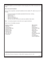
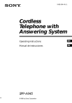
PROPT20
Installation Guide
Installation Guide For:
TWO-WAY
TELEMATICS MODULE
PROPT20
The tracking unit is a GPS-Cellular based telematic module which will not only locate your vehicle in
case of theft but, based on certain available options, allow the consumer to access the vehicle and
control specific functions from the Internet, or from a touch-tone phone. All connections of this interface unit must be made and tested in accordance with the instructions provided. Once the unit has
been installed and tested, you must advise your customer that the unit will not operate unless they
activate the unit as described in the documentation provided. Once the personal information on the
form is completed the form must be sent via FAX. The tracking unit must be connected to a host
alarm, alarm/remote start or ASPTUGM in order for the customer to receive automatic door violation.
WARNING: While this device is in operation, a separation distance of at least 20 centimeters
(7.87 in.), must be maintained between the radiating antenna and the body of all passengers in the
vehicle in order to meet the FCC exposure guidelines:
WIRING:
2 Pin Power Connector Red/Black:
Red: (+12 Volts) Connect the Red wire of the 2-pin connector to a constant on + 12 volt source
using the supplied fuse holder.
Black: (Ground) Connect the Black wire of the 2-pin connector to a clean metal surface of the
vehicle, or to a known chassis ground.
Antenna:
Cellular:
The control module houses the internal cellular antenna. To ensure best operation, the control
module must be mounted covertly near or above the belt line of the vehicle. High up behind the
dashboard is the preferred mounting location.
GPS:
The GPS antenna, which must also be covertly mounted, and must have a clear view of the sky
for operation. This means the rounded surface must point toward the sky without obstruction of any
metal object. Ideal mounting locations are the rear package shelf under the carpet or plastic padding, or under the top dashboard cover below the plastic padding.
The antenna comes with 10' of cable so it must be located within that distance of the control module.
When connecting the antenna, use caution not to overtighten the terminals as the fittings are press fit
and may loosen or break from the module. Be certain that the antenna is not located on or near any
other intentional radiator such as the vehicle radio antenna or a paging antenna that might have been
added to the vehicle. Once the location is chosen, using the cleaning pad, wipe the area clean, remove the backing from the double sided adhesive mounting pad and stick it to the antenna. Remove
the second backing from the double sided mounting pad and press in place. Route the connector to
the control module and attach to the GPS terminal.
-1-
The PROPT20 can be installed in 3 different configurations:
1. The first configuration is stand-alone mode and is not connected to any external vehicle
functions.
2. The second configuration is using the 5-pin auxiliary I/O connector. There is one
ground trigger input, three ground outputs and one ground source. The chart on page 3
shows the operation of each wire.
3. The third configuration is using the 4-pin data harness connected to a host control device such
as an Alarm, Alarm/Remote Start or ASPTUGM. Connect the 4-pin data harness into the
PROPT20 and the alarm/remote start module or ASPTUGM. The customer will receive
automatic door violations and theft notification when the host system is armed or locked.
REMEMBER: This unit is a tracking module, locating the components in such a manner as
they cannot easily be found is the best defense against a thief circumventing your efforts.
5-Pin Auxiliary Input/Output Wiring
Pin 1 Blue wire- If connected to the Horn Wire of a vehicle's theft deterrent system, when 10
negative pulses occur within 15 seconds while the vehicle is not running, the unit will send a
"Vehicle Alarm Trigger Notification" to the vehicle owner’s predefined event notification e-mail
addresses and or phone numbers. 300mA max output
This wire can accept a negative input only, if the vehicle switches + to the horn, a relay must be
used to invert the pulse to negative before connecting to this input.
Pin 2 Green wire - This wire provides a pulsed ground output whenever the Arm or Lock command is sent. Typically this wire will connect to the vehicle’s negative door lock wire. 300mA max
output.
Pin 3 Brown wire - This wire provides a pulsed ground output whenever the Disarm, Disarm/
unlock or unlock only command is sent. Typically this wire will connect to the vehicles negative
unlock wire. 300mA max output.
Pin 4 Orange wire - This wire provides constant ground whenever the Arm /lock or Activate
Disable vehicle command is sent. This wire goes open when the Disarm/unlock or deactivate
"disable vehicle" command is sent. Typically this wire is used for a starter interrupt relay. Follow the
diagram on page 3 for wiring of the relay.
Pin 5 Black wire - This wire provides low current constant ground. 300mA max output.
The timing for the AUX1 (green wire) and AUX2 (brown wire) can be changed during the initial
installation test. The timing choices are:
1. 700ms
2. 1 second
3. 3.5 seconds
4. Double 1 second pulse
-2-
Pos
Color
Operation
Trigger
Result
Pin 1
Blue
Input 1
Ground pulse 10 times within 15 sec
when VCC is less then 12.85
“Alarm 1” on web
Notification sent
Pin 2
Green
AUX 1 Output
“Arm/Lock” command
Pulsed negative output
Pin 3
Brown
AUX 2 Output
“Disarm/unlock” command
“Unlock only” command
Pulsed negative output
Pulsed negative output
Pin 4
Orange
AUX 3 Output
“Arm/Lock” command
“Disarm/Unlock” command
Activate “Disable vehicle” command
Deactivate “Disable vehicle” command
Constant ground signal
No ground signal
Constant ground signal
No ground pulse
Pin 5
Black
Output
Constant ground
Constant ground
Starter Inhibit Wiring Detail
Initial Power Sequence:
1. Make sure the vehicle is not in an enclosed area (garage or installation bay) and that the
antenna has a clear unobstructed view of the sky.
2. Connect 2-pin power connector into the PROPT20.
3. Connect the 4 Pin data harness between the PROPT20 and the Alarm, Alarm/Remote Start or
ASPTUGM system if installed.
4. Connect the 5-pin AUX I/O connector if used.
5. On power up the red LED will turn on first and then the green LED will turn on to indicate
network availability.
6. The unit must be powered up for 10 minutes before testing.
7. The unit must be tested before customer can register.
-3-
Tracking Device Functional Testing and Configuration
Voice Prompt Interface (VPI) Installer
Step 1: Peel off and place the IMEI and TPC number label included in the product’s packaging on the
Wireless Service Application form in the designated location. This information may also be
copied from the bottom of the device being installed.
Step 2: Call 800-705-8766 from any touch tone telephone when you are ready to test the device. You
will hear “ Welcome to your vehicle command center” Followed by several choices. Select
option number 4 for Dealer services. Then enter the installer identification number (8378) for
the Automated Dealer Installing and testing the system.
Step 3: Device Identification:
You will hear “WELCOME TO THE AUTOMATED DEALER INSTALLATION AND
TESTING SYSTEM. PLEASE ENTER THE IMEI NUMBER LOCATED ON THE BOTTOM OF
THE DEVICE.
Step 4: Installer Identification:
You will hear “NEXT PLEASE ENTER THE TEMPORARY PASS CODE, (TPC), LOCATED
ON THE BOTTOM OF THE DEVICE YOU ARE INSTALLING NOW, FOLLOWED BY THE #
SIGN.”
Step 5: GPS Receiver Verification:
Once the device has been configured it needs to be tested to ensure the network’s ability to
reach the device, and of the device’s ability to obtain a valid GPS position from the satellites.
This test requires the vehicle to be parked in an open space with a clear view of the sky to
maximize the GPS and communication signal. The VPI will introduce the GPS test phase
and prompt you to press “1” when you are ready to test. The system will send a locate
command to the vehicle as soon as “1” is pressed – this test can take up to three minutes.
The system will provide you with the vehicle location.
Step 6 : Unit Configuration :
Depending if and which host control system is being installed, you may have not been able to
utilize all the available functions of this system. To confirm controls available to your
customer you must inform the VPI which functions and featues you have installed. It is the
responsibility of the installer to record the proper configuration using the Installer VPI to insure
the user has a good initial experience with the device.
First you will hear a series of prompts about configuring controls. (A control allows the user
to send a command to the vehicle) The VPI will ask if you have installed the door lock
feature, for yes press 1, for no press 2. The VPI will then ask you to configure the rest of the
control features, which are door unlock, remote start, Auxiliary Output 1 and Auxiliary Starter
Interrupt. Follow the same process as noted above. The website and the vehicle command
center, (VPI), telephone interface will be dynamically set up to reflect the connected control
features.
-4-
Note: Until the installation is successfully completed, the user cannot register his device. After a
successful installation, you will not be able to use the temporary Pass Code to access the device
further.
After a Successful Installation:
Once you have completed a successful installation with the Installer VPI, make sure you do the
following:
•
•
•
•
•
•
Provide the subscriber all materials associated with the device, including:
Registration form(s)
Owner’s Guide
Terms and conditions
Wireless service agreement
Inform the user which functions and controls are available in their vehicle
Note: It is extremely important to instruct the user to register their device.
Below is a list of all available commands:
Telephone Interface
1. Arm/Lock
2. Disarm/Unlock
3. Remote Engine Start
4. Speed Alert On
5. Vehicle Location
6. Speed Alert Off
7. Geo Fence On
8. Geo Fence Off
0. Theft Reset
Web Interface
Arm/Lock
Disarm/Unlock
Remote Engine Start
Unlock Only
Starter Interrupt
Theft Reset
Auto Repair
Excessive Speed Alert
Geo Fence
Low Battery Alert
Remote Diagnostics
© 2009 Audiovox Electronics Corporation, 150 Marcus Blvd., Hauppauge, New York 11788
128-7913
-5-