1
instruction manual
AXB-DTMF+
DTMF+ Interface
AXlink Bus Controllers
AMX Limited Warranty and Disclaimer
AMX Corporation warrants its products to be free of defects in material and workmanship under normal use for
three (3) years from the date of purchase from AMX Corporation, with the following exceptions:
•
Electroluminescent and LCD Control Panels are warranted for three (3) years, except for the display and touch
overlay components that are warranted for a period of one (1) year.
•
Disk drive mechanisms, pan/tilt heads, power supplies, MX Series products, and KC Series products are
warranted for a period of one (1) year.
•
Unless otherwise specified, OEM and custom products are warranted for a period of one (1) year.
•
Software is warranted for a period of ninety (90) days.
•
Batteries and incandescent lamps are not covered under the warranty.
This warranty extends only to products purchased directly from AMX Corporation or an Authorized AMX Dealer.
AMX Corporation is not liable for any damages caused by its products or for the failure of its products to perform.
This includes any lost profits, lost savings, incidental damages, or consequential damages. AMX Corporation is not
liable for any claim made by a third party or by an AMX Dealer for a third party.
This limitation of liability applies whether damages are sought, or a claim is made, under this warranty or as a tort
claim (including negligence and strict product liability), a contract claim, or any other claim. This limitation of
liability cannot be waived or amended by any person. This limitation of liability will be effective even if AMX
Corporation or an authorized representative of AMX Corporation has been advised of the possibility of any such
damages. This limitation of liability, however, will not apply to claims for personal injury.
Some states do not allow a limitation of how long an implied warranty last. Some states do not allow the limitation or
exclusion of incidental or consequential damages for consumer products. In such states, the limitation or exclusion of
the Limited Warranty may not apply. This Limited Warranty gives the owner specific legal rights. The owner may
also have other rights that vary from state to state. The owner is advised to consult applicable state laws for full
determination of rights.
EXCEPT AS EXPRESSLY SET FORTH IN THIS WARRANTY, AMX CORPORATION MAKES NO
OTHER WARRANTIES, EXPRESSED OR IMPLIED, INCLUDING ANY IMPLIED WARRANTIES OF
MERCHANTABILITY OR FITNESS FOR A PARTICULAR PURPOSE. AMX CORPORATION
EXPRESSLY DISCLAIMS ALL WARRANTIES NOT STATED IN THIS LIMITED WARRANTY. ANY
IMPLIED WARRANTIES THAT MAY BE IMPOSED BY LAW ARE LIMITED TO THE TERMS OF THIS
LIMITED WARRANTY.
Table of Contents
Table of Contents
Product Information .................................................................................................1
Specifications .................................................................................................................... 1
Configuration and Installation .................................................................................3
Setting the Internal Jumpers ............................................................................................. 3
Auto Answer mode................................................................................................................... 3
Line Setting mode .................................................................................................................... 4
Wiring the AXB-DTMF+..................................................................................................... 4
Preparing captive wires............................................................................................................ 4
Wiring guidelines...................................................................................................................... 4
Connecting External Telephone Lines .............................................................................. 5
Audio In ............................................................................................................................. 5
Audio Out .......................................................................................................................... 5
Testing the AXB-DTMF+ ................................................................................................... 6
Off-hook line and off-hook phone troubleshooting ................................................................... 6
Programming ............................................................................................................7
Send_Commands.............................................................................................................. 7
Operative Send_Commands.................................................................................................... 7
Timing System Send_Commands.......................................................................................... 10
Fine Tuning Send_Commands .............................................................................................. 14
Distinctive Ring Patterns and Send_Commands ............................................................ 15
Changing a Default Ring Pattern ........................................................................................... 16
Distinctive Ring Send_Commands......................................................................................... 17
Axcess Program Example ............................................................................................... 18
Channel Codes................................................................................................................ 22
Caller ID .......................................................................................................................... 24
Program Example for Caller ID .............................................................................................. 24
AXB-DTMF+ DTMF+ Interface
i
Table of Contents
ii
AXB-DTMF+ DTMF+ Interface
Product Information
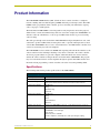
Product Information
The AXB-DTMF+ DTMF Interface (FIG. 1) links an Axcess central controller to a telephone
network, enabling dual tone multi-frequency (DTMF) and audio pass-through control. The AXBDTMF+, with a programmed central controller, processes incoming calls and initiates outgoing
calls to any pager or cellular phone.
The multi-function AXB-DTMF+ can be integrated for many imaginative and creative purposes
within a home or work environment using touch-tone control. For example, the AXB-DTMF+ can
announce callers by caller ID data, or can set up an audible menu selection to process incoming
calls for routing.
The audio pass-through can be used with an AXC-SPE Enhanced Speech Synthesizer card, or PC
sound card to produce audible menus, monitor phone audio, or provide audio input such as music
on hold. The AXB-DTMF+ allows a user to issue instructions to the AMX Central controller from
a remote location using any touch-tone telephone.
The AXB-DTMF+ receives and decodes DTMF audio signaling and sends the decoded data to the
central controller for the switching/controlling of any devices connected to the central controller.
An Axcess program written on a personal computer, and downloaded to the central controller,
enables the central controller to interpret the data received from the AXB-DTMF+. The program
may also issue menu selections over the telephone through an optional AXC-SPE card. For more
information about programming a central controller, refer to the Axcess Programming Guide.
Specifications
The following table lists the product specifications for the AXB-DTMF+.
AXB-DTMF+ Specifications
Power requirement
12 VDC
Power consumption
80 mA
DTMF+ Monitoring
The AXB-DTMF+ can monitor DTMF signals only when in an off-hook state or
when a phone attached to the extension connection is taken off-hook.
Incoming signal detection
• DTMF tones
• Ring
• Distinctive ring
• Caller ID
Outgoing signal detection
• DTMF tones
• Ring
• Busy
• Call termination
• Dial tone
Hardware state detection
Detects if the AXB-DTMF+ is off-hook, or if the extension phone is off-hook.
Control
Provides control for:
• AXB-DTMF+ off-hook/hangup
• Auto answer
• Extension phone on/disable
• Audio to telephone, and telephone to audio pass-through coupling
AXB-DTMF+ DTMF+ Interface
1
Product Information
AXB-DTMF+ Specifications (Cont.)
Operation modes (set via
internal jumpers):
• Auto Answer
• Line Type
Refer to Setting the Internal Jumpers section on page 3 for details.
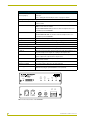
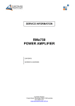
Front panel components (FIG. 1):
AXlink LED
Blinks on and off to indicate that the AXB-DTMF+ is communicating with the
central controller.
Off Hook Phone LED
Lights when ever a telephone connected to the PHONE connector on the AXBDTMF+ is in an off-hook condition.
The OFF HOOK PHONE LED only functions when the telephone line is connected directly to the AXB-DTMF+.
Off Hook Line LED
Lights when the AXB-DTMF+ is taken off-hook.
The OFF HOOK LINE LED only functions when the telephone line is connected directly to the AXB-DTMF+.
Ring LED
Lights when an incoming call ring is detected.
DTMF RX LED
Lights when the AXB-DMTF+ is receiving DTMF signals.
DTMF TX LED
Lights when the AXB-DMTF+ is transmitting DTMF signals out.
Rear panel components:
Phone connector
This RJ-11 connector is used for attaching a telephone.
Line connector
This RJ-11 input connects the incoming telephone line to the AXB-DTMF+.
Audio In
RCA connector that provides unbalanced line level audio input signals for coupling to the telephone line signals for coupling to the telephone line..
Audio Out
RCA connector that provides an output for unbalanced line level (1V p-p) audio
signals coupled from coupled from the telephone line.
AXlink
4-pin captive-wire connector that provides power and communications with the
Axcess central controller.
Weight
1.0 lbs (454.0 g)
Dimensions (HWD)
1.51" x 5.55" x 6.45" (38.4 mm x 141 mm x 165 mm)
Mounting options
• Flat mount
• Rack mount (using an optional AC-RK accessory rack kit).
AXlink
OFF
HOOK
PHONE
DEVICE
OFF
HOOK
LINE
RING
DTMF
RX
DTMF
TX
OUT
AUDIO
AXP
IN
PWR
LINE
AXM
PHONE
GND
ON
AXlink
FIG. 1 Front and rear views of the AXB-DTMF+
2
AXB-DTMF+ DTMF+ Interface
Configuration and Installation
Configuration and Installation
Setting the Internal Jumpers
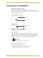
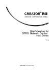
There are two 2-position jumpers on the AXB-DTMF+ circuit card (FIG. 1). Each jumper is set to a
default pin setting. These jumpers are positioned to enable automatic call answering and select line
setting for a leased line or phone operation.
Audio In pot
JP1
JP1 - Line selection
JP2
JP2 - Auto Answer
front
FIG. 1 Location of JP1, JP2 jumpers, and Audio In potentiometer.
Auto Answer mode
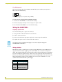
The 2-position jumper JP2 selects auto answer ON or OFF mode when the system powers on.
When the auto answer is on, the AXB-DTMF+ answers on the ring set by the Send_Command
COUNT-XXX. If the ring count is set to 3, for example, auto answer picks up the call after the
third ring. The default count is 1 ring. The default jumper setting is shown in FIG. 2.
pin 3
pin 2
pin 1
Auto Answer ON
Auto Answer OFF
FIG. 2 Auto answer jumper JP2 (default setting = Auto Answer ON)
To change the auto answer default from ON to OFF:
1. Remove the AXB-DTMF+ unit cover.
2. Remove the jumper from pins 2 and 3, and place it on pins 1 and 2.
3. Re-install the AXB-DTMF+ cover onto the unit housing.
AXB-DTMF+ DTMF+ Interface
3
Configuration and Installation
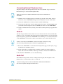
Line Setting mode
The 2-position jumper JP1 selects PHONE or LEASED line operation when system powers on.
FIG. 3 shows the default setting.
pin 3
pin 2
pin 1
Phone
Leased
FIG. 3 Line Setting jumper JP1 (default setting = PHONE)
To change the line setting default from PHONE to LEASED:
1. Remove the AXB-DTMF+ cover from the unit housing.
2. Remove the jumper from pins 2 and 3, and place it on pins 1 and 2.
3. Re-install the AXB-DTMF+ cover onto the unit housing.
Wiring the AXB-DTMF+
Preparing captive wires
To connect the wiring into a captive-wire connector:
1. Strip 1/4 inch off the wire insulation for all four wires.
2. Tin 2/3 of the exposed wire.
3. Insert each wire into the appropriate captive-wire connector up to the insulation.
4. Tighten the captive screws to secure the fit in the connector.
If the device is using a separate power supply, do not connect the power wiring from
the AXB-DTMF+ to that device.
Wiring guidelines
The interface requires a 12 VDC power to operate properly. The interface uses a PSN2.8 power
suppl. The Central Controller supplies power via the AXlink cable or external 12 VDC power
supply. The maximum wiring distance between the Central Controller and interface is determined
by power consumption, supplied voltage, and the wire gauge used for the cable. The table below
lists wire sizes and maximum lengths allowable between the AXB-DTMF+ and Central Controller.
The maximum wiring lengths for using AXlink power are based on a minimum of 13.5 volts
available at the Central Controller’s power supply.
Wiring Guidelines at 80 mA
Wire Size Maximum Wiring Length
4
18 AWG
1467.14 feet (447.18 m)
20 AWG
928.22 feet (282.92 m)
22 AWG
578.70 feet (176.39 m)
24 AWG
364.79 feet (111.19 m)
AXB-DTMF+ DTMF+ Interface
Configuration and Installation
Connecting External Telephone Lines
Telephone cabling for both the input and extension lines are standard RJ-11 type connections.
Follow these steps to connect external telephone lines.
Cables and connectors for telephone and audio hook-up are not included with the
AXB-DTMF+.
1. Check the circuit card jumper settings to match line type and auto answer mode. For more
information, refer to AXB-DTMF+ Jumpers in the Pre-Installation section of this manual.
2. Connect the AXlink cable to the Axcess Central controller AXlink input.
3. Connect the male RJ-11 jack of the incoming telephone line input to the AXB-DTMF+ LINE
jack and the extension telephone cable to the PHONE jack on the rear of the AXB-DTMF+.
4. Adjust the AUDIO OUT level by referring to the Audio Pass-Through Level paragraphs in this
section.
Audio In
The audio in is provided for music on hold or for voice menu selections if connected. If the audio
volume is too low or too high, the audio in level needs to be adjusted. Increase or decrease the audio
in pass-through level (gain) from the AXB-DTMF+. The AUDIO IN pot is located about mid-center
on the AXB-DTMF+ circuit board (see FIG. 1). Perform these steps to adjust the audio in level.
If audio is connected to the AXB-DTMF+, make sure the audio is turned on by using
the correct Send_Commands. Refer to the Axcess Programming section.
1. Remove the AXB-DTMF+ cover from the unit housing. Then, apply an audio signal (1 V p-p
maximum) to the AUDIO IN connector.
2. Listen on-line and use a small flat-blade screwdriver to turn the pot counter clockwise to
reduce audio level from AUDIO IN. Turn the pot clockwise to increase the AUDIO IN level.
3. Re-install the AXB-DTMF+ cover onto the unit housing.
Audio Out
The AUDIO OUT jack provides a means of routing line level signals, which originates on the
telephone line to an external device such as a sound card.
To prevent "howling", make sure that the AXB-DTMF+ AUDIO IN and AUDIO OUT
lines are not looped back through an external device.
AXB-DTMF+ DTMF+ Interface
5
Configuration and Installation
Testing the AXB-DTMF+
Follow these steps to test the AXB-DTMF+:
1. Disconnect AXlink power.
2. Remove the cover from the unit housing and set the AUTO ANSWER jumper to AUTO ANSWER
ON then reinstall the cover on the unit housing.
3. Reconnect AXlink power. The status LEDs should blink in sequence from right to left and the
AXlink green LED should be blinking.
4. Place a call to the AXB-DTMF+ from an outside line.
5. The RING LED should light with an incoming ring.
6. The OFF HOOK LINE LED should light after 1 ring.
7. The DTMF RX LED should light when tones are sent from the calling telephone.
8. Check line quality and operation using an extension telephone connected to the PHONE jack.
9. Return the AUTO ANSWER jumper to OFF position, if desired.
Off-hook line and off-hook phone troubleshooting
The off-hook line and off-hook phone LEDs light only if there is a good telephone line connection.
If either the off-hook line or off-hook phone LED fails to light, a faulty telephone line connection is
indicated.
Make sure a proper phone line connection exists to light both off-hook and extension off-hook
LEDs. Test the off-hook line by following these test procedures:
The extension telephone is optional and supplied by the user.
1. Take the AXB-DTMF+ off-hook by issuing the off-hook Send_Command from the central
controller. If there is a good telephone line connection, then the OFF HOOK LINE LED lights.
2. If the OFF HOOK LINE LED fails to light, then there is a bad or faulty telephone line
connection. Check the incoming telephone line and make sure it is working properly. Then,
check the RJ-11 cable and its connection to the AXB-DTMF+.
Test the off-hook phone using the following steps:
1. Take the receiver off the extension telephone. If there is a good telephone line connection, then
the EXTENSION OFF HOOK LED lights.
2. If the OFF HOOK PHONE LED fails to activate, make sure that an extension off-hook
Send_Command has not been issued (you can do a Send_Command extension on-hook to be
sure; see the Operative Send_Commands section on page 7 for details). If this does not
produce results, then there is a faulty telephone line connection. Check the incoming telephone
line and make sure it is working properly. Then, check the RJ-11 cable and its connection to
the AXB-DTMF+. Make sure the RJ-11 cable from the extension telephone is good.
6
AXB-DTMF+ DTMF+ Interface
Programming
Programming
Program the AXB-DTMF+ to send outbound DTMF codes using Axcess Send_Commands from
the control
Fine Tuning - commands allowing experienced users the ability to obtain performance in adverse
system. Use the commands described in this section with the Axcess Programming Guide to
program the AXB-DTMF+. The Send_Commands are divided into the following categories:
!
Operative: normal day-to-day commands controlling the overall operation of the AXBDTMF+.
!
Timing: control the AXB-DTMF+ signal timing (not necessary in most
situations).conditions.
!
Distinctive Ring: commands that define distinctive ring patterns.
Send_Commands
Send_Commands are stored in the central controller and direct the AXB-DTMF+ to perform
various operations.
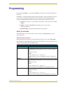
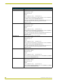
Operative Send_Commands
The following table lists Operative Send_Commands that produce control of the AXB-DTMF+.
The commands are listed alphabetically by operation and include syntax, syntax descriptions, usage
examples, time increments, and reset default values.
Operative System Send_Commands
Command
Description
AGAIN-OFF
Control gain of the audio (voice) signal from the phone lines to the audio output
of the AXB-DTMF+. Setting the gain to off causes it to return to the default
level.
Default at reset = YES
Example:
SEND_COMMAND DTMF, 'AGAIN-OFF'
Sets the audio gain to low from the AXB-DTMF+ to default (no amplification
boost).
AGAIN-ON
Control gain of the audio (voice) signal from the phone lines to the audio output
of the AXB-DTMF+. Setting the gain to on increases the gain above the default
level.
Default at reset = NO
Example:
SEND_COMMAND DTMF, 'AGAIN-ON'
Sets the audio gain from the AXB-DTMF+ to high (amplification boost).
AUDIO-OFF
Disable audio from passing through the AXB-DTMF+ to the phone line.
Default at reset = YES
Example:
SEND_COMMAND DTMF, 'AUDIO-OFF'
Disables the audio from passing through the AXB-DTMF+ to the phone line.
AXB-DTMF+ DTMF+ Interface
7
Programming
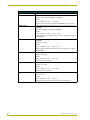
Operative System Send_Commands (Cont.)
Command
Description
AUDIO-ON
Enable audio from passing through the AXB-DTMF+ to the phone line.
Default at reset = YES (for backwards compatibility)
Example:
SEND_COMMAND DTMF, 'AUDIO-ON'
Enables the audio from passing through the AXB-DTMF+ to the phone line.
AUDOUT-OFF
Disable audio from passing from the phone line to the audio out output of the
AXB-DTMF+.
Default at reset = NO (for backwards compatibility)
Example:
SEND_COMMAND DTMF, 'AUDOUT-OFF'
Disables the audio from passing from the phone line to the audio out output of
the AXB-DTMF+.
AUDOUT-ON
Enable audio from passing from the phone line to the audio out output of the
AXB-DTMF+.
Default at reset = NO
Example:
SEND_COMMAND DTMF, 'AUDOUT-ON'
Enables the audio from passing from the phone line to the audio out output of
the AXB-DTMF+.
AUTO-ON
Enable the auto answer mode (overrides the auto-answer jumper settings).
Default at reset = NO
Example:
SEND_COMMAND DTMF, 'AUTO-ON'
Enables the auto answer mode.
AUTO-OFF
Disable auto answer mode (overrides the auto-answer jumper settings).
Default at reset = YES
Example:
SEND_COMMAND DTMF, 'AUTO-OFF'
Disables the auto answer mode.
COUNT-XXX
Set auto answer ring count.
Default at reset = 1
Example:
SEND_COMMAND DTMF, 'COUNT-4'
Sets ring count to 4 before the line is answered in auto answer mode.
8
AXB-DTMF+ DTMF+ Interface
Programming
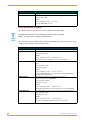
Operative System Send_Commands (Cont.)
Command
Description
DIAL-X-XXX-XXXX
Dial number and send DTMF.
• Spaces or hyphens are ignored when dialing.
• A 'W' in the dial command will cause the AXB-DTMF+ to wait for dial tone
before dialing the next digit in the dial command. The wait will time out after 2
seconds. If a time out occurs, the AXB-DTMF+ will indicate this by sending a
push and release on channel 45.
• A ',' in the Dial command will cause the AXB-DTMF+ to pause for a time
specified in the Pause Send_Command before dialing the next digit in the
command.
Example:
SEND_COMMAND DTMF, 'DIAL-9 W 214,644-3048'
Causes the AXB-DTMF+ to dial a 9 and then waits for dial tone before continuing to dial the next three digits. The AXB-DTMF+ pauses for the time specified
in the Pause Send_Command before dialing the remaining six digits.
Up to 24 characters following Dial are allowed. Characters that generate tones
are 0 - 9, *, #, A - D.
Note: Tone length is set by the Tone Time Send_Command which sets the
length of each generated tone and the time between tones. A pause can be
added after a tone, for additional dial time, by using the Pause
Send_Command. For more information refer to the 'TONE TIME-XXX ' and
'PAUSE-XXX ' Send_Commands.
EXTEN-OFF
Disable phones which are hanging off the extension phone connection on the
AXB-DTMF+ by opening the phone circuit.
Default at reset = NO
Example:
SEND_COMMAND DTMF, 'EXTEN-OFF'
Disables phones that are hanging off the extension phone connection on the
AXB-DTMF+ by opening the phone circuit.
EXTEN-ON
Enable phones that are hanging off the extension phone connection on the
AXB-DTMF+ by closing the phone circuit.
Default at reset = YES
Example:
SEND_COMMAND DTMF, 'EXTEN-ON'
Enables any phones that are hanging off the extension phone connection on
the AXB-DTMF+ by closing the phone circuit.
FLASH
Cause flash-hook for a period of time set by the Send_Command FLASH
TIME.
Example:
SEND_COMMAND DTMF, 'FLASH'
Causes flash-hook for a period of time set by the Send_Command FLASH
TIME.
'OFF HOOK
Place AXB-DTMF+ off hook.
Default at reset = NO
Example:
SEND_COMMAND DTMF, 'OFF HOOK'
Places the AXB-DTMF+ off hook.
AXB-DTMF+ DTMF+ Interface
9
Programming
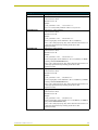
Operative System Send_Commands (Cont.)
Command
Description
ON HOOK
Place AXB-DTMF+ on hook.
Default at reset = YES
Example:
SEND_COMMAND DTMF, 'ON HOOK'
Places the AXB-DTMF+ on hook.
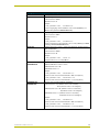
Timing System Send_Commands
The following table lists the commands, which establish normal signal timing.
Changing default time values may inadvertently alter the operation of the AXBDTMF+. It is unnecessary to change most default values.
The commands are listed alphabetically by operation and include syntax, syntax descriptions, usage
examples, time increments, and reset default values.
Timing System Send_Commands
Command
Description
BLOCKRDET-XXX
For telephone lines with distinctive ring feature.
Time increment = 10 ms
Example:
SEND_COMMAND DTMF, 'BLOCKRDET-185'
Sets the time to ignore "sub rings " at 1.85 seconds (1850 ms).
FLASH TIME-XXX
Set time AXB-DTMF+ will go "on-hook" when Send_Command FLASH is
issued.
• Time increment = 10 ms
• Default at reset = 63
Example:
SEND_COMMAND DTMF, 'FLASH TIME-65'
Sets time AXB-DTMF+ will go "on-hook" when Send_Command FLASH is
issued for .65 seconds (650 ms).
INROFFMIN-XXX
Minimum time required for an incoming ring to be in the off
state to reset ring count on AXB-DTMF+.
• Time increment = 100 ms
• Default at reset = 45
Example:
SEND_COMMAND DTMF, 'INROFFMIN-55'
Sets minimum off state time for an incoming ring to 5.5 seconds (5500 ms).
LOSSLCMAX-XXX
The maximum time a loop current is off (used to detect other end hung up).
• Time increment = 10 ms
• Default at reset = 80
Example:
SEND_COMMAND DTMF, 'LOSSLCMAX-90'
Sets a .9 second (900 ms) maximum off time for a loop current.
10
AXB-DTMF+ DTMF+ Interface
Programming
Timing System Send_Commands (Cont.)
Command
Description
LOSSLCMIN-XXX
The minimum time a loop current is off (used to detect other end hung up).
• Time increment = 10 ms
• Default at reset = 10
Example:
SEND_COMMAND DTMF, 'LOSSLCMIN-15'
Sets a .15 second (150 ms) minimum off time for a loop current.
OBUOFFMAX-XXX
Outgoing busy off time maximum.
• Time increment = 10 ms
• Default at reset = 60
Example:
SEND_COMMAND DTMF, 'OBUOFFMAX-65'
Sets the outgoing busy off time maximum to .65 second (650 ms).
For the code to work properly, ring, busy, and reorder time values must be set
so that ring is greater than busy, and busy greater than reorder
(ring>busy>reorder).
OBUOFFMIN-XXX
Outgoing busy off time minimum.
• Time increment = 10 ms
• Default at reset = 40
Example:
SEND_COMMAND DTMF, 'OBUOFFMIN-45'
Sets the outgoing busy off time minimum to .45 second (450 ms) (see NOTE
for Send_Command 'OBUOFFMAX-XXX ').
For the code to work properly, ring, busy, and reorder time values must be set
so that ring is greater than busy, and busy greater than reorder
(ring>busy>reorder).
OBUONMAX-XXX
Outgoing busy on time maximum.
• Time increment = 10 ms
• Default at reset = 60
Example:
SEND_COMMAND DTMF, 'OBUONMAX-65'
Sets the outgoing busy on time maximum to .65 second (650 ms) (see NOTE
for Send_Command 'OBUOFFMAX-XXX ').
For the code to work properly, ring, busy, and reorder time values must be set
so that ring is greater than busy, and busy greater than reorder
(ring>busy>reorder).
OBUONMIN-XXX
Outgoing busy on time minimum.
• Time increment = 10 ms
• Default at reset = 40
Example:
SEND_COMMAND DTMF, 'OBUONMIN-50'
Sets the outgoing busy on time minimum to .5 second (500 ms) (see NOTE for
Send_Command 'OBUOFFMAX-XXX ').
For the code to work properly, ring, busy, and reorder time values must be set
so that ring is greater than busy, and busy greater than reorder
(ring>busy>reorder).
AXB-DTMF+ DTMF+ Interface
11
Programming
Timing System Send_Commands (Cont.)
Command
Description
OREOFFMAX-XXX
Outgoing reorder (fast busy) off time maximum.
• Time increment = 10 ms
• Default at reset = 35
Example:
SEND_COMMAND DTMF, 'OREOFFMAX-45'
Sets the outgoing reorder (fast busy) off time maximum to .45 second (450 ms)
(see NOTE for Send_Command 'OBUOFFMAX-XXX ').
For the code to work properly, ring, busy, and reorder time values must be set
so that ring is greater than busy, and busy greater than reorder
(ring>busy>reorder).
OREOFFMIN-XXX
Outgoing reorder (fast busy) off time minimum.
• Time increment = 10 ms
• Default at reset = 15
Example:
SEND_COMMAND DTMF, 'OREOFFMIN-20'
Sets the outgoing reorder (fast busy) off time minimum to .20 second (200 ms)
(see NOTE for Send_Command 'OBUOFFMAX-XXX ').
For the code to work properly, ring, busy, and reorder time values must be set
so that ring is greater than busy, and busy greater than reorder
(ring>busy>reorder).
OREONMIN-XXX
Outgoing reorder (fast busy) on time minimum.
• Time increment = 10 ms
• Default at reset = 15
Example:
SEND_COMMAND DTMF, 'OREONMIN-20'
Sets the outgoing reorder (fast busy) on time minimum to .20 second (200 ms)
(see NOTE for Send_Command 'OBUOFFMAX-XXX ').
For the code to work properly, ring, busy, and reorder time values must be set
so that ring is greater than busy, and busy greater than reorder
(ring>busy>reorder).
ORIOFFMAX-XXX
Outgoing ring off time maximum.
• Time increment = 100 ms
• Default at reset = 44
Example:
SEND_COMMAND DTMF, 'ORIOFFMAX-50'
Sets the outgoing ring off time maximum to 5.0 seconds (5,000 ms) (see NOTE
for Send_Command 'OBUOFFMAX-XXX ').
ORIOFFMIN-XXX
Outgoing ring off time minimum.
• Time increment = 100 ms
• Default at reset = 26
Example:
SEND_COMMAND DTMF, 'ORIOFFMIN-40'
Sets the outgoing ring off time minimum to 4.0 seconds (4,000 ms) (see NOTE
for Send_Command 'OBUOFFMAX-XXX').
12
AXB-DTMF+ DTMF+ Interface
Programming
Timing System Send_Commands (Cont.)
Command
Description
ORIONMAX-XXX
Outgoing ring on time maximum.
• Time increment = 100 ms
• Default at reset = 22
Example:
SEND_COMMAND DTMF, 'ORIONMAX-30'
Sets the outgoing ring on time maximum to 3.0 seconds (30,000 ms) (see
NOTE for Send_Command 'OBUOFFMAX-XXX').
ORIONMIN-XXX
Outgoing ring on time minimum.
• Time increment = 100ms
• Default at reset = 8
Example:
SEND_COMMAND DTMF, 'ORIONMIN-25'
Sets the outgoing ring on time minimum to 2.5 seconds (2,500 ms) (see NOTE
for Send_Command 'OBUOFFMAX-XXX').
PAUSE-XXX
Set pause time for the comma (,) symbol in the Dial Send_Command (refer to
'DIAL-X-XXX-XXXX ').
• Time increment = 100 ms
• Default at reset = 20
Example:
SEND_COMMAND DTMF, 'PAUSE-25'
Sets pause time to 2.5 seconds (2500 ms).
ROHOFFMAX-XXX
Receiver off-hook off time minimum or maximum.
ROHOFFMIN-XXX
• MAX and MIN time increment = 10 ms
• MAX default at reset = 140
• MIN default at reset = 1
Example:
SEND_COMMAND DTMF, 'ROHOFFMAX-65'
Sets the receiver off-hook off time minimum to .065 second (65 ms)
SEND_COMMAND DTMF, 'ROHOFFMIN-110'
Sets the receiver off-hook on time minimum to .11 second (110 ms)
ROHONMAX-XXX
Receiver off-hook off time minimum or maximum.
ROHONMIN-XXX
• Time increment = 1 ms (firmware version 2.11 and lower)
10 ms (firmware version 2.12 and higher)
• MAX default at reset = 140 (firmware version 2.11 and lower)
10 (firmware version 2.12 and higher)
• MIN default at reset = 1 (firmware version 2.11 and lower)
10 (firmware version 2.12 and higher)
Example:
SEND_COMMAND DTMF, 'ROHONMAX-65'
Sets the receiver off-hook off time minimum to .065 second (65 ms)
SEND_COMMAND DTMF, 'ROHONMIN-110'
Sets the receiver off-hook on time minimum to .11 second (110 ms)
AXB-DTMF+ DTMF+ Interface
13
Programming
Timing System Send_Commands (Cont.)
Command
Description
TONE TIME-XXX
Set length of each generated tone and time between tones in the Dial
Send_Command (refer to 'DIAL-X-XXX-XXXX')
• Time increment = 1 ms
• Default at reset = 100 ms
Example:
SEND_COMMAND DTMF, 'TONE TIME-100'
Sets tone time length to .11 second (110 ms).
Fine Tuning Send_Commands
The following table lists the commands that fine tune AXB-DTMF+ signal timing. Most likely, you
will not have to change Fine Tuning parameters.The commands are listed alphabetically by
operation and include syntax, syntax descriptions, usage examples, time increments, and reset
default values.
Fine Tuning Send_Commands
Command
Description
CPGAIN-OFF
When off does not add gain (in addition to IGAIN) to dial tone call progress signal.
Default at reset = YES
Example:
SEND_COMMAND DTMF, 'CPGAIN-OFF'
Sets gain into call progress detector chip as default.
CPGAIN-ON
When on adds gain (in addition to IGAIN) to dial tone call progress signal.
Default at reset = NO
Example:
SEND_COMMAND DTMF, 'CPGAIN-ON'
Sets gain into call progress detector chip as default.
IGAIN-OFF
Controls gain of "internal signals" on the AXB-DTMF+. The internal signals are
call progress tones such as incoming DTMF, receiver off-hook, and called number is busy. Setting gain to "off" causes it to return to default level.
Default at reset = YES
Example:
SEND_COMMAND DTMF, 'IGAIN-OFF'
Sets internal gain on AXB-DTMF+ to default.
IGAIN-ON
Controls gain of "internal signals" on AXB-DTMF+. The internal signals are call
progress tones such as incoming DTMF, receiver off-hook, and called number
is busy. Setting gain to "on" increases gain above default level. This may be
helpful if signals are not being detected due to attenuation over the phone line.
Default at reset = NO
Example:
SEND_COMMAND DTMF, 'IGAIN-ON'
Sets internal gain on the AXB-DTMF+ to high.
14
AXB-DTMF+ DTMF+ Interface
Programming
Distinctive Ring Patterns and Send_Commands
Distinctive ringing is a service provided by the local telephone company. Distinctive ring allows
additional phone numbers to be assigned to a single phone line. Then, depending upon the number
dialed, the ringing pattern is different.
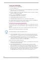
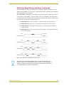
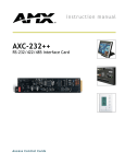
The AXB-DTMF+ can identify up to four distinctive ring default patterns. Default time values for
each pattern are shown in FIG. 1. A pattern consists of five parts. Depending on the ring pattern, a
part is either high or low. The distinctive ring patterns shown illustrate the envelope of the incoming
ring with respect to time. The four default patterns are:
!
Default Pattern 1: 1 long ring lasting 2 seconds followed by 4 seconds of silence.
!
Default Pattern 2: 2 rings, in a 2 second period, followed by 4 seconds of silence.
!
Default Pattern 3: 2 short rings and 1 long ring, in a 2 second period, followed by 4
seconds of silence.
!
Default Pattern 4: 1 short, 1 long, and 1 short ring, within a 2 second period, followed
by 4 seconds of silence.
1
2000ms
Part
2, 3, 4 and 5
Default pattern 1
0 ms
Part
1
800ms
Default pattern 2
Part
Default pattern 4
3
800ms
4 and 5
0 ms
400ms
1
400ms
Default pattern 3
Part
2
2
200ms
1
2
300ms
200ms
3
4
400ms
5
800ms
200ms
3
1000ms
4
5
300ms
200ms
FIG. 1 DTMF+ distinctive ring default patterns and time values
Time values are in milliseconds (1000 ms equals 1 second). All 4 distinctive ring
patterns are within a 2-second period from start to end time, for most applications. If
you plan to change any of the distinctive ring patterns, it is advisable to stay within a 2
second time frame for each distinctive ring pattern.
AXB-DTMF+ DTMF+ Interface
15
Programming
Changing a Default Ring Pattern
Change a default ring pattern using the appropriate Send_Command when programming the AXBDTMF+. Each ring pattern consists of five parts with each part having a specific Send_Command.
For more information on distinctive ring Send_Commands, refer to Distinctive Ring
Send_Commands.
Example:
Pattern 4's five parts are as follows:
!
Part 1 is high and 300 ms (.3 seconds) long (ring).
!
Part 2 is low and 200 ms (.2 seconds) long (no ring).
!
Part 3 is high and 1000 ms (1 seconds) long (ring).
!
Part 4 is low and 200 ms (.2 seconds) long ( no ring).
!
Part 5 is high and 300 ms (.3 seconds) long (ring).
If you want to change the time values of Parts 2 and 4 (no ring) of Pattern 3:
Values specified are in increments of 10 ms. That is, a value of 1 yields 10 ms, while
a value of 100 yields 100 x 10 ms, or 1 second.
1. To change Part 2 of Pattern 3, use the Send_Command 'P3_2-XXX' where:
!
Time increment = 10 ms
!
Default at reset = 20 (20 x 10 ms = 200 ms)
For example, issue the Send_Command
SEND_COMMAND DTMF, 'P3_2-25 '
(25 x 10 ms = 250 ms)
to change Part 2 of Pattern 3 from a value of 200 ms (.2 seconds) to 250 ms (.250
seconds).
2. To change Part 4 of Pattern 3, use the Send_Command 'P3_4-XXX' where:
!
Time increment = 10 ms
!
Default at reset = 20 (20 x 10ms = 200ms)
For example, issue the Send_Command
SEND_COMMAND DTMF, 'P3_4-25 '
(25 x 10ms = 250ms)
to change Part 4 of Pattern 3 from a value of 200 ms to (.2 seconds) to 250 ms (.250
seconds).
3. The normal length of time from the start of any pattern to its end time is usually 2- seconds. If
you increase the time value for any part of a pattern, make sure to decrease another part by the
same amount, maintaining the 2- seconds overall time for the pattern. For example, if you
increased the value of Parts 2 and 4 of Pattern 3 by 5 ms each, decrease Part 3 by 10 ms.
16
AXB-DTMF+ DTMF+ Interface
Programming
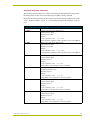
Distinctive Ring Send_Commands
The following Send_Commands are available for changing the default distinctive ring patterns.
Each ring pattern consists of five parts with each part requiring a Send_Command.
Distinctive ring Send_Commands produce four patterns (P1 through P5) and high and low time
values (_X). Refer to FIG. 1 on page 15 to see the timing diagram based on defaults at start-up/
reset.
Distinctive Ring Send_Commands
Command
Description
P1_1-XXX
Pattern 1 Part 1 high time for distinctive ring.
• Time increment = 10 ms
• Default at reset = 200
Example:
SEND_COMMAND DTMF, 'P1_1-300'
Sets the distinctive ring Pattern 1 Part 1 high time for 3.0 seconds (3000 ms).
P1_1-XXX
Pattern 1 Part 1 high time for distinctive ring.
• Time increment = 10 ms
• Default at reset = 200
Example:
SEND_COMMAND DTMF, 'P1_1-300'
Sets the distinctive ring Pattern 1 Part 1 high time for 3.0 seconds (3000 ms).
P1_2-XXX
Pattern 1 Part 2 low time for distinctive ring.
• Time increment = 10 ms
• Default at reset = 0
Example:
SEND_COMMAND DTMF, 'P1_2-05'
Sets the Pattern 1 Part 2 low time for .05 seconds (50 ms).
P1_3-XXX
Pattern 1 Part 3 high time for distinctive ring.
• X=(Time increment) = 10 ms
• Default at reset = 0
Example:
SEND_COMMAND DTMF, 'P1_3-05'
Sets the Pattern 1 Part 3 high time for .05 seconds (50 ms).
P1_4-XXX
Pattern 1 Part 4 low time for distinctive ring.
• Time increment = 10 ms
• Default at reset = 0
Example:
SEND_COMMAND DTMF, 'P1_4-05'
Sets the Pattern 1 Part 4 low time for .05 seconds (50 ms).
P1_5-XXX
Pattern 1 Part 5 high time for distinctive ring.
• Time increment = 10 ms
• Default at reset = 0
Example:
SEND_COMMAND DTMF, 'P1_5-05'
Sets the Pattern 1 Part 5 high time for .05 seconds (50 ms).
AXB-DTMF+ DTMF+ Interface
17
Programming
Distinctive Ring Send_Commands (Cont.)
Command
Description
PY_Z-XXX
The remaining Ring Patterns and Parts Send_Commands are used just like the
examples shown for Pattern 1 above. Refer to Figure 12 and the following information.
• Y = Pattern number
• Z = Part number
• X = Time increment
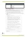
Axcess Program Example
To program the AXB-DTMF+, you will need a personal computer with the Axcess software
program, an Axcess Central controller, an AXlink power/data cable, as well as an CC-COM Axcess
programming cable. For the program example, complete the following steps:
1. Create a new Axcess program. Then, add the following Axcess programming data from the
following example into the Define_Start section of the new Axcess program.
2. Compile the Axcess program and download it to the central controller to program the AXBDTMF+.
PROGRAM_NAME='REDIAL'
(*
DATE:04/15/96
TIME:15:04:04
*)
(********************************************************************)
(*
REDIAL.AXS
(*
THIS PROGRAM IMPLEMENTS AN AUTOMATIC DIALER THAT DIALS
*)
*)
(*
A NUMBER IN RESPONSE TO A BUTTON PUSH ON A KEYPAD.
*)
(*
NUMBER IS BUSY, THE USER IS NOTIFIED VIA A RS232 TERMINAL
*)
(*
ATTACHED TO THE SERIAL PORT ON THE MASTER, AND THE CARD
*)
(*
WILL RETRY 6 ADDITIONAL TIMES AT 5 SECOND INTERVALS.
*)
(*
DIALED NUMBER RINGS, THE USER WILL BE NOTIFIED VIA A RS232
*)
(*
TERMINAL ATTACHED TO THE SERIAL PORT ON THE MASTER
*)
IF THE
IF THE
(*
*)
(*
NOTE THAT TO DEMO THIS PROGRAM,
A MASTER, A AXB-DTMF+,
(*
A PC RUNNING AXCESS, AND A PHONE LINE ARE ALL THAT ARE
*)
(*
NECESSARY (IN ADDITION TO AN AXCESS CARDFRAME).
*)
(*
*)
*)
(*
MODIFY THIS PROGRAM WHERE THE COMMENT "(* INSERT DESIRED
*)
(*
NUMBER HERE IN PLACE OF 555-1212 *)" IS WRITTEN.
REPLACE THE
*)
(*
NUMBER 555-1212 WITH THE NUMBER THAT IS DESIRED TO BE CALLED.
*)
(*
*)
(*
AFTER THE PROGRAM HAS BEEN DOWNLOADED TO THE
*)
(*
MASTER CARD, HIGHLIGHT THE LINE "PUSH[128,1]" AND PRESS
*)
(*
CONTROL 'A ' ON THE PC KEYBOARD.
*)
(*
TERMINAL PROGRAM.
(*
SHOULD BE SEEN.
THEN, PRESS F4 TO ENTER THE
PROGRESS MESSAGES FROM THE MASTER
*)
*)
(*********************************************************************)
(*********************************************************************)
(*
DEVICE NUMBER DEFINITIONS GO BELOW
*)
(*********************************************************************)
DEFINE_DEVICE
DTMF_CARD = 96
(*
AXB-DTMF+
*)
(*********************************************************************)
Continued
18
AXB-DTMF+ DTMF+ Interface
Programming
(*
CONSTANT DEFINITIONS GO BELOW
*)
(*********************************************************************)
DEFINE_CONSTANT
(*********************************************************************)
(*
VARIABLE DEFINITIONS GO BELOW
*)
(*********************************************************************)
DEFINE_VARIABLE
STATE
(*
STATE OF THE SOFTWARE "STATE MACHINE"
BUSY_COUNT
(*
NUMBER OF RETRIES
*)
*)
(*********************************************************************)
(*
LATCHING DEFINITIONS GO BELOW
*)
(*********************************************************************)
DEFINE_LATCHING
(*********************************************************************)
(*
MUTUALLY EXCLUSIVE DEFINITIONS GO BELOW
*)
(*********************************************************************)
DEFINE_MUTUALLY_EXCLUSIVE
(*********************************************************************)
(*
STARTUP CODE GOES BELOW
*)
(*********************************************************************)
DEFINE_START
BUSY_COUNT=0
STATE=255
(*
ESSENTIALLY "NO STATE"
*)
(*********************************************************************)
(*
THE ACTUAL PROGRAM GOES BELOW
*)
(*********************************************************************)
DEFINE_PROGRAM
(*********************************************************************)
(*
IF KEY 1 ON THE KEYPAD IS PUSHED, PLACE THE
*)
(*
CARD ON HOOK
*)
(*
WAIT 2 SECONDS BEFORE CHANGING STATE
(*
STATE 2.
(IN CASE IT WAS OFF-HOOK).
TO
*)
*)
(*********************************************************************)
PUSH[128,1]
(*
1
* )
{
SEND_COMMAND DTMF_CARD,'ON HOOK'
WAIT 20
STATE=2
}
(*********************************************************************)
(*
TAKE THE CARD OFF-HOOK.
(*
FOR DIAL TONE. IF IT IS ( NOT RECEIVED, SEND AN
WAIT 2 SECONDS
*)
(*
ERROR MESSAGE AND
*)
SHUT DOWN (GO TO ( "NO STATE").
*)
(*********************************************************************)
Continued
AXB-DTMF+ DTMF+ Interface
19
Programming
IF(STATE=2)
{
STATE=3
SEND_COMMAND DTMF_CARD,'OFF-HOOK'
WAIT 20 'WAIT FOR DIAL TONE'
{
SEND_STRING 0,"'ERROR: NO DIAL TONE',13,10"
SEND_COMMAND DTMF_CARD,'ON HOOK'
STATE=255
}
}
(***********************************************************************)
(*
IF DIAL TONE IS RECEIVED, DIAL THE NUMBER
*)
(***********************************************************************)
IF(STATE=3)
{
PUSH[DTMF_CARD,47](*DIAL_TONE*)
{
CANCEL_WAIT 'WAIT FOR DIAL TONE'
SEND_COMMAND DTMF_CARD,'DIAL 555-1212'(* INSERT DESIRED
NUMBER HERE IN PLACE OF 555-1212 *)
STATE=4
}
}
(***********************************************************************)
(*
IF 12 SECONDS PASS AND THERE IS NO BUSY OR RINGING, SEND
*)
(*
AN ( ERROR MESSAGE AND SHUT DOWN (GO TO "NO STATE").
*)
(***********************************************************************)
IF(STATE=4)
{
STATE=5
WAIT 120 'WAIT FOR RESPONSE TO DIAL'
{
SEND_STRING 0,"'ERROR: NO RESPONSE TO DIAL',13,10"
SEND_COMMAND DTMF_CARD,'ON HOOK'
STATE=255
}
}
(***********************************************************************)
(*
IF THE DIALED NUMBER IS BUSY, SEND A MESSAGE INDICATING
*)
(*
SUCH ( AND GO TO STATE 6. IF THE DIALED NUMBER IS RINGING,
*)
(*
INDICATE
*)
SUCH AND SHUT DOWN (GO TO "NO STATE").
(***********************************************************************)
Continued
20
AXB-DTMF+ DTMF+ Interface
Programming
IF(STATE=5)
{
PUSH[DTMF_CARD,34] (*OUTGOING_BUSY*)
{
CANCEL_WAIT 'WAIT FOR RESPONSE TO DIAL'
SEND_COMMAND DTMF_CARD,'ON HOOK' (*NUMBER IS
BUSY SO HANG UP*)
SEND_STRING 0,"'DIALED NUMBER IS BUSY',13,10"
STATE=6
}
PUSH[DTMF_CARD,35] (*OUTGOING_RING*)
{
CANCEL_WAIT 'WAIT FOR RESPONSE TO DIAL'
SEND_STRING 0,"'REMOTE PHONE RINGING',13,10"
BUSY_COUNT=0
STATE=255
}
}
(***********************************************************************)
(*
IF THE DIALED NUMBER WAS BUSY, INCREMENT THE
*)
(*
"BUSY_COUNT".IF THIS IS NOT THE 7TH RETRY, WAIT 5.
*)
(*
SECONDS AND TRY AGAIN ELSE, SHUT DOWN (GO TO "NO
*)
(*
STATE").
*)
(***********************************************************************)
IF(STATE=6)
{
BUSY_COUNT = BUSY_COUNT+1
STATE=255
IF(BUSY_COUNT<7)
{
WAIT(50)
STATE=2
}
ELSE
{
SEND_STRING 0,"'MAXIMUM RETRIES HAS BEEN REACHED',13,10"
BUSY_COUNT=0
}
}
(**********************************************************************)
(*
(*
END OF PROGRAM
DO NOT PUT ANY CODE BELOW THIS COMMENT
*)
*)
(**********************************************************************)
AXB-DTMF+ DTMF+ Interface
21
Programming
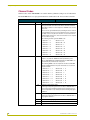
Channel Codes
Channel codes on the AXB-DTMF+ are stored in memory (firmware) and process all outbound or
inbound DTMF from a set of program instructions downloaded to the Axcess Central controller.
Channel Codes
Operation
DTMF Tones
Channel # Description (ON Indicates)
1-16
Outbound tones are produced by the AXB-DTMF+ by
Send_Commands received from the Axcess Central controller to
dial a phone number or send a sequence of DTMF codes over the
phone line.
Tones are also generated directly by activating the device channel
corresponding to the tone. A tone is played as long as a channel is
on. Only one tone may be active at a time. If a second channel is
activated while another is on, this causes the first tone to stop and
the second tone to play.
The following channels generate DTMF code:
Detection
17-32
• Channel 1 = 1
• Channel 9 = 9
• Channel 2 = 2
• Channel 10 = 0
• Channel 3 = 3
• Channel 11 = *
• Channel 4 = 4
• Channel 12 = #
• Channel 5 = 5
• Channel 13 = A
• Channel 6 = 6
• Channel 14 = B
• Channel 7 = 7
• Channel 15 = C
• Channel 8 = 8
• Channel 16 = D
Detects DTMF "in" from an extension or phone.
Refers to any inbound DTMF transmitted (forwarded) to the
Axcess AXC-EM Enhanced Master Card by the AXB-DTMF+, as
generated by any external touch-tone phone.
The following DTMF codes are reported to the Axcess AXC-EM
Enhanced Master Card on the push and release of a touch-tone
telephone button.
34
• Channel 17 =
1
• Channel 25 =
9
• Channel 18 =
2
• Channel 26 =
0
• Channel 19 =
3
• Channel 27 = *
• Channel 20 =
4
• Channel 28 =
#
• Channel 21 =
5
• Channel 29 =
A
• Channel 22 =
6
• Channel 30 =
B
• Channel 23 =
7
• Channel 31 =
C
• Channel 24 =
8
• Channel 32 =
D
Indicates outgoing busy signal.
Call Progress Reporting returned to the Axcess AXC-EM when a
busy signal is detected. During Call Progress Reporting, the system is responsible for any subsequent action following a progress
indication.
35
Indicates outgoing ring signal.
Call Progress Reporting returned to the Axcess AXC-EM when a
ring signal is detected.
22
36
Indicates incoming ring signal (each burst indicated).
37
Indicates AXB-DTMF+ is off-hook.
38
Indicates extension phone is off-hook.
AXB-DTMF+ DTMF+ Interface
Programming
Channel Codes (Cont.)
Operation
Detection (Cont.)
Channel # Description (ON Indicates)
39
Indicates a momentary loss of loop current (call termination).
Call Progress Reporting returned to the Axcess AXC-EM when
call termination is detected.
Detection of call termination (other end hung up) is usually provided by the telephone company and is activated by a momentary
loss of loop current. However, if this is not available, the DTMF+ is
triggered by the receiver off-hook tone which occurs approximately
1 minute after call termination.
40
Indicates receiver off-hook tone.
Call Progress Reporting returned to the Axcess AXC-EM when a
receiver off-hook is detected.
Distinctive Ring
45
Indicates time out while waiting for the dial tone during a wait (W)
in the Dial Send_Command.
47
Indicates dial tone presence.
41-44
The AXB-DTMF+ provides report capability for the type of ring
received. Distinctive ringing is a service that must be obtained
from the telephone company. This service allows the same telephone line to be reached by dialing different telephone numbers.
The receiving telephone then rings in a distinctive manner according to the number dialed.
The AXB-DTMF+ provides 4 distinctive ring type patterns.
These default patterns can be changed and are as follows:
41
Default Pattern 1
The first ring lasts 2 seconds followed by 4 seconds of silence.
42
Default Pattern 2
There are 2 long rings in a 2 second period followed by 4 seconds
of silence.
43
Default Pattern 3
There are 2 short then 1 long ring in a 2 second period followed by
4 seconds of silence.
44
Default Pattern 4
There is 1 short, 1 long, and 1 short ring within a 2 second period
followed by 4 seconds of silence.
AXB-DTMF+ DTMF+ Interface
23
Programming
Caller ID
The AXB-DTMF+ provides report capability for receiving Caller ID information. The following
table shows the Caller ID data string sent to the Axcess AXC-EM Enhanced Master Card. A
description and format use are also described.
Caller ID
Data String
Description
"'CLID-mmddhhii-nnnnnnnnnn-<text>',0"
Caller ID data string sent from the AXB-DTMF+ to
the central controller. Caller ID is a service obtained
from the telephone company and is passed from the
central office between the first and second incoming
ring.
Characters in this string are not literal ASCII except
'CLID' and '- ' characters. All other characters in the
string are represented as follows:
• m = month
• d = day
• h = hour
• l = min
• n = phone number
• text = 0 to 20 characters
The string is always 48 bytes including the null character. Spaces (0x20) are used as filler in the text field
or for any field not received.
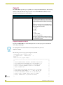
Program Example for Caller ID
Program the AXB-DTMF+ for Caller ID using the Axcess software program as described in
Axcess Program Example.
For the program to work, Caller ID service must be provided from your local
telephone company.
The following is an Axcess program example for Caller ID.
PROGRAM_NAME='DTMF+ CALLER-ID SAMPLE'
(*
DATE:07/29/96
TIME:15:15:53
*)
Figure 17
AXCESS Caller ID program example
(***********************************************************************)
Continued
24
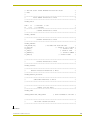
(*
*)
(* THIS PROGRAM RECEIVES CALLER-ID INFORMATION IN THE FORM
*)
(* OF A STRING FROM AN INCOMMING CALL (VIA AXB-DTMF+). IT
*)
(* THEN DISPLAYS IT ON FOUR BUTTONS ON A TOUCHPANEL AND
*)
(* ALSO ON A DISPLAY TERMINAL HOOKED UP TO THE MASTER
*)
(* CARD'S PROGRAM PORT.
*)
(*
*)
(* JUST CREATE FOUR VARIABLE TEXT BUTTONS ON A TOUCHPANEL
*)
(* WITH VARIABLE TEXT NUMBERS 1, 2, 3, AND 4 AND SEE THE
*)
(* CALLER-ID INFORMATION APPEAR. OR, YOU CAN WATCH THE
*)
(* DATA ON YOUR PC SCREEN. SELECT <CTRL>-T TO ENTER
*)
(* AXCESS' TERMINAL MODE TO SEE THE DATA APPEAR.
*)
(*
*)
AXB-DTMF+ DTMF+ Interface
Programming
(* THE DATA SHOULD APPEAR BETWEEN THE FIRST AND SECOND
*)
(* RING.
*)
(*
*)
(***********************************************************************)
(*
DEVICE NUMBER DEFINITIONS GO BELOW
*)
(***********************************************************************)
DEFINE_DEVICE
DTMF =
TP
96
= 128
(* AXB-DTMF+
V X.XX
*)
(* TOUCHPANEL
*)
(***********************************************************************)
(*
CONSTANT DEFINITIONS GO BELOW
*)
(***********************************************************************)
DEFINE_CONSTANT
(***********************************************************************)
(*
VARIABLE DEFINITIONS GO BELOW
*)
(***********************************************************************)
DEFINE_VARIABLE
DTMF_BUFFER[100]
(* INCOMING DATA FROM DTMF CARD
ID_DATA[100]
*)
(* CALLER-ID COPY OF ABOVE *)
ID_DATE[5]
(* CALLER-ID DATE
ID_TIME[5]
(* CALLER-ID TIME
ID_NUMBER[12]
*)
*)
(* CALLER-ID NUMBER *)
ID_NAME[20]
(* CALLER-ID NAME
*)
(***********************************************************************)
(*
LATCHING DEFINITIONS GO BELOW
*)
(***********************************************************************)
DEFINE_LATCHING
(***********************************************************************)
(*
MUTUALLY EXCLUSIVE DEFINITIONS GO BELOW
*)
(***********************************************************************)
DEFINE_MUTUALLY_EXCLUSIVE
(***********************************************************************)
(*
SUBROUTINE DEFINITIONS GO BELOW
*)
(***********************************************************************)
(***********************************************************************)
(*
STARTUP CODE GOES BELOW
*)
(***********************************************************************)
DEFINE_START
CREATE_BUFFER DTMF,DTMF_BUFFER
(* START LISTENING TO THE CARD *)
(***********************************************************************)
(*
THE ACTUAL PROGRAM GOES BELOW
*)
(***********************************************************************)
Continued
AXB-DTMF+ DTMF+ Interface
25
Programming
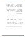
DEFINE_PROGRAM
IF (FIND_STRING(DTMF_BUFFER,'CLID-',1))
(* START OF STRING FOUND *)
{
WAIT 20 'NO VALID STRING FOUND'
(* TIME-OUT AFTER 2.0 SECONDS
*)
{
CANCEL_WAIT_UNTIL 'WAIT FOR END OF STRING' (* DON'T WAIT FOR THE REST *)
CLEAR_BUFFER DTMF_BUFFER
(* CLEAR DATA IN BUFFER *)
SEND_STRING 0,"'INCOMPLETE STRING RECEIVED',10,13"
(* ERROR MESSAGE *)
}
WAIT_UNTIL (FIND_STRING(DTMF_BUFFER,"$00",1))
(* END OF STRING FOUND *)
{
CANCEL_WAIT 'NO VALID STRING FOUND'
ID_DATA = DTMF_BUFFER
(* NO TIME-OUT NECESSARY *)
(* COPY CONTENTS, SO MORE DATA *)
(*
WILL NOT AFFECT PROCESSING *)
CLEAR_BUFFER DTMF_BUFFER
(* CLEAR DATA IN BUFFER *)
(* PROCESS THE DATA FOUND *)
ID_DATE
= "MID_STRING(ID_DATA,6,2),'/',MID_STRING(ID_DATA,8,2)"
ID_TIME
= "MID_STRING(ID_DATA,10,2),':',MID_STRING(ID_DATA,12,2)"
ID_NUMBER = "MID_STRING(ID_DATA,15,3),'-',
MID_STRING(ID_DATA,18,3),'-',MID_STRING(ID_DATA,21,4)"
ID_NAME
(*
=
MID_STRING(ID_DATA,26,20)
NOTE: THE FOLLOWING DATA WILL APPEAR ON THE TOUCHPANEL
SEND_COMMAND TP,"'TEXT1-NAME:
',ID_NAME"
SEND_COMMAND TP,"'TEXT2-NUMBER: ',ID_NUMBER"
*)
(*
CALLER'S NAME
*)
(*
CALLER'S NUMBER
*)
SEND_COMMAND TP,"'TEXT3-DATE:
',ID_DATE"
(* DATE OF THE CALL *)
SEND_COMMAND TP,"'TEXT4-TIME:
',ID_TIME"
(* TIME OF THE CALL *)
(*
NOTE: THE FOLLOWING DATA WILL APPEAR IN THE TERMINAL EMULATOR
SEND_STRING 0,"'NAME:
',ID_NAME,10,13"
SEND_STRING 0,"'NUMBER: ',ID_NUMBER,10,13"
*)
(* CALLER'S NAME *)
(* CALLER'S NUMBER *)
SEND_STRING 0,"'DATE:
',ID_DATE,' (MONTH/DATE)',10,13" (* DATE OF CALL *)
SEND_STRING 0,"'TIME:
',ID_TIME,10,13"
(* TIME OF CALL *)
}
}
(***********************************************************************)
(*
(*
END OF PROGRAM
DO NOT PUT ANY CODE BELOW THIS COMMENT
*)
*)
(***********************************************************************)
26
AXB-DTMF+ DTMF+ Interface
Programming
AXB-DTMF+ DTMF+ Interface
27
brussels • dallas • los angeles • mexico city • philadelphia • shanghai • singapore • tampa • toronto • york
3000 research drive, richardson, TX 75082 USA • 469.624.8000 • 800.222.0193 • fax 469.624.7153 • technical support 800.932.6993
032-004-1334 5/02 ©2002 AMX Corporation. All rights reserved. AMX, the AMX logo, the building icon, the home icon, and the light bulb icon are all trademarks of AMX Corporation.
AMX reserves the right to alter specifications without notice at any time. *In Canada doing business as Panja Inc.
AMX reserves the right to alter specifications without notice at any time.