1
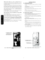
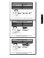
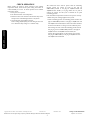
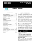
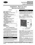
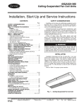
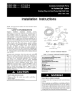
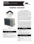
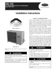
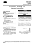
53DS---900--- --- ---086
53DS---900--- --- ---095
Duct---Free Systems
Cooling Only and Heat Pump Units
Low Ambient Temperature Control Accessory
Installation Instructions
NOTE: Read and become familiar with these instructions before
beginning installation.
SAFETY CONSIDERATIONS
Installing and servicing air--conditioning equipment can be
hazardous due to system pressures and electrical components. Only
trained and qualified personnel should install or service
air--conditioning equipment. When working on air--conditioning
equipment, observe the precautions provided in literature, tags, and
labels attached to the unit.
Follow all safety codes. Wear safety glasses, protective clothing,
and work gloves. Use quenching cloth for brazing operations.
Have fire extinguisher available. Read these instructions
thoroughly and follow all warnings or cautions included in
literature and attached to the unit. Consult local building codes and
National Electrical Code (NEC) for special requirements.
Recognize safety information. This is the safety--alert symbol !! .
When you see this symbol on the unit and in instructions or
manuals, be alert to the potential for personal injury.
Understand these signal words: DANGER, WARNING, and
CAUTION. These words are used with the safety--alert symbol.
DANGER identifies the most serious hazards which will result in
severe personal injury or death. WARNING signifies hazards
which could result in personal injury or death. CAUTION is used
to identify unsafe practices which may result in minor personal
injury or product and property damage. NOTE is used to highlight
suggestions which will result in enhanced installation, reliability, or
operation.
!
GENERAL
IMPORTANT: Heat pump models require an isolation relay and
field wiring to prevent fan cycling in heat pump mode. See Table 1
for isolation relay part numbers.
Table 1 – Isolation Relay Part Numbers
Models
38MVQ009/012
38MVQ012
38MVQ018/024
38QRR/QRF
538B_R/538Q_R
RCD
Part No.
P283--- 0291
P283--- 0292
P283--- 0292
P283--- 0293
P283--- 0293
Voltage
120v
240v
240v
24v
24v
Wind baffles are required for low ambient operation. For 38HD,
38QR and 538B models, the baffles are a factory accessory (see
Table 2 for part numbers). For 38MVC and 38MVQ models, the
baffles are field fabricated using factory drawings (see Table 2 for
drawing numbers).
Table 2 – Wind Baffle Accessories for R--410A Units
Models
38HDF/QRF/HDR/QRR018
538E_F/538Q_F018
38HDF/38HDR024, 38HDF030,
38QRF/38QRR024
538E_F/538A_R024
538E_F030
538Q_F/538B_R024
38HDF036/38QRF030/035/036,
38HDR/38QRR030/036
538E_F036
538Q_F030/035/036,
538A_R/538B_R030/036
38HDR/QRR048,060
538A_R/538B_R048,060
WARNING
ELECTRICAL SHOCK HAZARD
Failure to follow this warning could result in personal injury
or death.
Before beginning any modification or installation of this kit,
be sure the main electrical disconnect is in the OFF position.
Ensure power is disconnected to the fan coil unit. On some
systems both the fan coil and the outdoor unit may be on the
same disconnect. Tag the disconnect switch with a suitable
warning label. There may be more than one disconnect.
Models
38MVC/38MVQ009
38MVC/38MVQ012
38MVC/38MVQ018
38MVC/38MVQ024
*Drawings available on HVAC Partners.
1
Wind Baffle Part No.
53DS--- 900--- --- --- 070
53DS--- 900--- --- --- 087
53DS--- 900--- --- --- 071
53DS--- 900--- --- --- 088
Wind Baffle Drawing
No.*
53DS--- 900--- --- --- 097
53DS--- 900--- --- --- 097
53DS--- 900--- --- --- 098
53DS--- 900--- --- --- 099
Winter Start Control (part number KAAWS0101AAA) is
required when low ambient operation (cooling below 55_F/13_C)
is required for cooling and heat pump models (018--060) that have
a low pressure switch.
INSTALLATION
For 38HDR/QRR Models
1. Remove access panels and locate pressure tap on liquid
header.
2. Place three drops of compressor oil in the pressure switch
for lubrication.
3. Mount switch as shown in Fig. 1.
4. For heat pump units only, mount isolation relay in control
box.
5. Connect wiring as shown in Fig. 3 or Fig. 4.
6. Coil any excess wire and secure next to the pressure switch.
53DS-- 900-- -- -- 086, 095
The Winter Start Control kit uses a time--delay relay to bypass the
low--pressure switch for three (3) minutes on start--up. the time
delay relay will take the low pressure switch out of the control
circuit to allow the system to build pressure eliminating nuisance
trips. Units with low pressure switches: 38HDR/HDF/QRR/QRF
and 538A_B/E_F, 538Q_F.
Crankcase Heater is required for low ambient operation and must
be added. This is a separate accessory to be installed.
These instructions cover the installation of low ambient
temperature control accessory kit on the duct--free cooling and heat
pump condensing units.
The low ambient temperature control (LAC) is a high cycle rate
pressure switch that directly controls the outdoor fan motor.
The low ambient temperature control is designed to maintain a
condensing pressure of 255 to 295 psig on models 38MVC/MVQ
and 321 to 362 psig for HDF/HDR and QRF/QRR models by
directly cycling the outdoor--fan motor. No field adjustments or
calibrations are required.
When unpacking the accessory, carefully inspect for shipping
damage. If damage is evident, return for replacement.
For 38MVC/MVQ Models
1. All of the components required for the correct installation of
the low ambient control are included in the kit.
2. Remove access panels and locate pressure tap on liquid line.
3. Place three drops of compressor oil in the pressure switch
for lubrication.
4. Mount switch as shown in Fig. 2.
5. For heat pump units only, mount isolation relay in control
box.
6. Determine locations for electrical connections (see Fig. 3 or
Fig. 5).
7. Cut pressure switch leads to correct length and apply the required terminations from the selection supplied in the low
ambient control kit.
8. For heat pump units only, use the cut off lead and terminations supplied with the kit to make up the required field
wires as shown in Fig. 5.
LOW AMBIENT CONTROL
PRESSURE SWITCH
PRESSURE TAP ON
COIL LIQUID HEADER
LOW AMBIENT CONTROL
PRESSURE SWITCH
PRESSURE TAP ON
COIL LIQUID LINE
D06005
A08046
Fig. 1 -- Representative of 38HDR/38QRR OR 538A/538B
Models
Fig. 2 -- Representative of 38MVC/38MVQ Models
2
COOLING ONLY MODELS
Wire Color
Black = 009 & 012
Red = 018 & 024
Black
Black
Black
Black
38MVC009--- 024
38HDF018--- 036
38HDR018--- 060
538A Series
538E Series
LAC
SEE CHART
FOR COLOR
BLU
TO TERMINAL
CONNECTION
MAIN POWER
BLU
FAN MOTOR
LEGEND
LAC = Low Ambient Control
A08047
Fig. 3 -- Low Ambient Temperature Control Wiring -- Cooling Only Models
HEAT PUMP MODELS
(Reversing Valve Energized in Cooling)
Model No.
Wire Color
38QRF018--- 036
Black
38QRR018--- 060
Black
538BNR018--- 060
Black
538QNF018--- 036
Black
4
3
"RVS" *(REVERSING VALVE)
IR
"RVS" *(REVERSING VALVE)
5
1
SEE CHART
FOR COLOR
LAC
OUTDOOR
FAN MOTOR
IR
=
LAC =
TO TERMINAL
CONNECTION
MAIN POWER
LEGEND
Isolation Relay
Low Ambient Control
*Isolation relay coil (low voltage) to be wired in parallel with the reversing valve.
A08048
Fig. 4 -- Low Ambient Temperature Control Wiring -- Heat Pump Models
(Reversing Valve Energized in Cooling)
HEAT PUMP MODELS
(Reversing Valve Energized in Heating)
Model No.
Wire Color
38MVQ009--- 012
Black
38MVQ018--- 024
Red
4
3
IR
2
RVS
1
Field Wire - Use cutoff wire from
LAC and terminations supplied in the kit.
SEE CHART
FOR COLOR
LAC
OUTDOOR
FAN MOTOR
TO TERMINAL
CONNECTION
MAIN POWER
LEGEND
IR
= Isolation Relay
LAC = Low Ambient Control
RVS = Reversing Valve Solenoid
*Isolation relay coil (line voltage) to be wired in parallel with the reversing valve.
A08049
Fig. 5 -- Low Ambient Temperature Control Wiring -- Heat Pump Models
(Reversing Valve Energized in Heating)
3
53DS-- 900-- -- -- 086, 095
Model No.
CHECK OPERATION
53DS-- 900-- -- -- 086, 095
Before starting the system to check operation of low ambient
temperature control, ensure that the power wiring and location of
control assembly are correct. To check operation of low ambient
temperature control:
1. Turn power on to system.
2. Set thermostat below room temperature.
3. Ensure that there is the standard 3--minute time delay for the
microprocessor controlled high wall fan coil systems.
4. Check time delay of installed accessories:
Under--ceiling (40QAC/QAQ) fan coils using the duct--free
24--v thermostat delay settings: 2 or 4 minute delay.
Copyright 2008 CAC / BDP S 7310 W. Morris St. S Indianapolis, IN 46231
The outdoor--fan motor will not operate until the condensing
pressure reaches the control set point of 295 psig for
38MVC/MVQ models or 362 psig for 38QRF--018--036 and
38QRR--018--060 models (± 10 psig). When the set point is
reached, the outdoor fan will cycle to maintain the set point
condensing pressure.
If the low ambient temperature control does not operate correctly:
S Ensure that power is being supplied to the system.
S Check condensing pressure: if condensing pressure is below 255
psig for 38MVC/MVQ models or 321 psig for 38QRF--018--036
and 38QRR--018--060 models, the outdoor--fan motor should be
off and there should be no voltage across the 2 blue fan power
leads coming out of the control. If condensing pressure is about
295 psig or greater for 38MVC/MVQ models or 362 psig for
38QRF--018--036 and 38QRR--018--060 models, the
outdoor--fan motor should be on and will cycle off at around
255 psig for 38MVC/MVQ or 321 psig for 38QRF--018--036
and 38QRR--018--060 models.
Printed in U.S.A.
Edition Date: 02/08
Manufacturer reserves the right to change, at any time, specifications and designs without notice and without obligations.
4
Catalog No: IIK-- 53DS900-- 06
Replaces: AG--53DS900--01