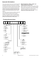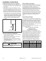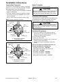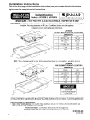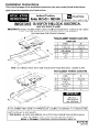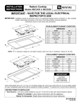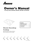
1
Service
This manual is to be used by qualified appliance
technicians only. Maytag does not assume any
responsibility for property damage or personal
injury for improper service procedures done by
an unqualified person.
UpDraft Electric
Cooktops
This Base Manual covers general information
Refer to individual Technical Sheet
for information on specific models
This manual includes, but is
not limited to the following:
AKT3040*
AKT3650*
CEC1430AA*
CEC1536AA*
JEC7430AA*
JEC8430AD*
JEC8536AD*
JEC8730AD*
JEC9530AD*
JEC9536AD*
MEC4430BD*
MEC5430BD*
MEC5536BA*
16022159
Revision 0
May 2003
Important Information
Important Notices for Servicers and Consumers
Maytag will not be responsible for personal injury or property damage from improper service procedures. Pride and
workmanship go into every product to provide our customers with quality products. It is possible, however, that during
its lifetime a product may require service. Products should be serviced only by a qualified service technician who is
familiar with the safety procedures required in the repair and who is equipped with the proper tools, parts, testing
instruments and the appropriate service information. IT IS THE TECHNICIANS RESPONSIBLITY TO REVIEW ALL
APPROPRIATE SERVICE INFORMATION BEFORE BEGINNING REPAIRS.
!
WARNING
To avoid risk of severe personal injury or death, disconnect power before working/servicing on appliance to avoid
electrical shock.
To locate an authorized servicer, please consult your telephone book or the dealer from whom you purchased this
product. For further assistance, please contact:
Customer Service Support Center
CAIR Center
Web Site
Telephone Number
WWW.AMANA.COM ................................................ 1-800-843-0304
WWW.JENNAIR.COM ............................................. 1-800-536-6247
WWW.MAYTAG.COM ............................................. 1-800-688-9900
CAIR Center in Canada ........................................... 1-800-688-2002
Amana Canada Product ........................................... 1-866-587-2002
Recognize Safety Symbols, Words, and Labels
! DANGER
DANGER—Immediate hazards which WILL result in severe personal injury or death.
!
WARNING
WARNING—Hazards or unsafe practices which COULD result in severe personal injury or death.
!
CAUTION
CAUTION—Hazards or unsafe practices which COULD result in minor personal injury, product or property
damage.
2
16022159 Rev. 0
©2003 Maytag Appliances Company
Table of Contents
Important Information .................................................. 2
Safety Information
Safety Procedures ................................................. 4
Safety Practices for Servicer .................................. 5
Before Installing ..................................................... 5
Receiving Cooktop ................................................. 5
Unpacking .............................................................. 5
Electrical Requirements ......................................... 5
Electrical Connection ............................................. 5
General Information
Model Identification Rating Label and
Ordering Replacement Parts ............................... 6
Cooking Nomenclature ........................................... 6
Model Identification ................................................ 7
Service ................................................................... 7
Parts and Accessories ........................................... 7
Extended Service Plan ........................................... 7
Troubleshooting Procedures ....................................... 8
Component Testing Information
Power Supply ......................................................... 9
Internal Wiring ........................................................ 9
Indicator Light ........................................................ 9
Warming Element (Infinite Switch) ......................... 9
Surface Elements (Infinite Switch) .......................... 9
Surface Elements (Dual Infinite Switch) ................ 10
Control ................................................................. 11
Temperature Sensor ............................................. 11
Ribbon Elements- Power Disconnected ............... 11
Ribbon Elements-Power Connected ..................... 11
Cooling Fan .......................................................... 11
High Limit Switch ................................................. 11
©2003 Maytag Appliances Company
Disassembly Procedures
Disassembly Procedures for Models Listed
AKT3040F/E/S
AKT3650F/E/S ................................................. 12
Main Top Removal ................................................ 12
Indicator Light Replacement ................................. 12
Element Replacement .......................................... 12
Infinite Switch Replacement ................................. 12
Disassembly Procedures for Models Listed
CEC1536AAB/W/Q/C
CEC1430AAB/W/Q/C
JEC7430AAB/W
MEC4430BDB/W/Q .......................................... 12
Main Top Removal ................................................ 12
Element Replacement .......................................... 12
Infinte Switch Replacement .................................. 12
Indicator Light Replacement ................................. 12
Receptacle Replacement ..................................... 12
Disassembly Procedures for Models Listed
JEC8430ADB/W/F/N/S
JEC8536ADB/W/F/N/S
MEC5430BDB/W/S
MEC5536BAB/W/S .......................................... 13
Main Top Removal ................................................ 13
Element Replacement .......................................... 13
Infinite Switch Replacement ................................. 13
Indicator Light Replacement ................................. 13
Disassembly Procedures for Models Listed
JEC9530ADB/F/S
JEC9536ADB/F/S ............................................. 13
Main Top Removal ................................................ 13
Element Replacement .......................................... 13
Sensor Replacement ............................................ 14
Limiter Replacement ............................................ 14
Infinite Replacement ............................................. 14
Electronic Infinite Replacement ............................ 14
Hi-Limit Switch Replacement ............................... 14
Indicator Light Replacement ................................. 14
Cooling Fan Replacement .................................... 14
Appendix A
Installation Instructions .......................... A–1 — A–6
16022159 Rev. 0
3
Safety Information
As with all appliances, there are certain rules to follow
for safe operation. Verify everyone who operates the
cooktop is familiar with the operations and with these
precautions.
Use appliance only for its intended purpose as
described. Pay close attention to the safety sections of
this manual.
Recognize the safety section by looking for the symbol
or the word safety.
Recognize this symbol as a safety precaution.
!
!
WARNING
General
1. The cooktop must be installed and/or repaired by an
authorized installer or servicer.
2. Never use the cooktop for warming or heating the
room.
3. Do not store items on the cooktop. Items stored on
the cooktop can become too hot and melt.
4. Wear proper apparel. Loose fitting or hanging
garments should never be worn while using
cooktop.
5. Do not repair or replace any part of the cooktop
yourself unless it is recommended in this manual.
6. Flammable materials should not be stored near
cooktop.
7. Use only dry potholders. Moist or damp potholders
on hot surfaces may result in burns from steam. Do
not let a potholder touch an element. Do not use a
towel or a bulky cloth as a potholder.
!
WARNING
Surface Cooking
1. Use the proper pan size. Select utensils with flat
bottoms large enough to cover the element.
Undersized utensils will expose the element to direct
contact with clothing.
2. Never leave surface units unattended. Boilovers can
cause smoking and may ignite.
3. To reduce risk of burns, ignition of flammable
materials or spillage due to unintentional contact,
utensil handles must be turned inward and not
extend over adjacent surface.
4. Only certain types of glass, glass/ceramic, ceramic,
earthware, or other glazed utensils are suitable for
cooktop use. Unsuitable utensils may break due to
the sudden temperature change.
5. Clean cooktop with caution. To avoid steam burns,
do not use a wet sponge or cloth to wipe up spills on
a hot cooking area.
6. Do not place aluminum foil or foods packaged in
aluminum foil directly on element.
Safety Procedures
!
WARNING
To avoid risk of electrical shock, property damage,
personal injury or death; verify wiring is correct, if
components were replaced. Verify proper and
complete operation of unit after servicing.
Due to the nature of cooking, fires can occur as a
result of overcooking or excessive grease. Although a
fire is unlikely, if one occurs proceed as follows:
Surface Element Fires
1. Do not turn on the vent hood. The fan can spread
the flames.
2. If it is safe to do so, turn the surface element to
OFF. Turn off main electrical supply.
3. Smother the fire with nonflammable lid or use a
Class “ABC” or “BC” fire extinguisher. Do not use
water on a grease fire.
Installation and service must be performed by an
authorized installer, service agency or gas supplier.
4
16022159 Rev. 0
©2003 Maytag Appliances Company
Safety Information
Safety Practices for Servicer
Electrical Requirements
Safe and satisfactory operation of electric cooktops
depends upon its design and proper installation.
However, there is one more area of safety to be
considered:
220-volt, 60 Hertz, individual circuit which is properly
grounded, polarized and protected by a circuit breaker
or fuse.
Installing the electric cooktop in compliance with local
electrical building codes results in proper operation and
consumer satisfaction with the cooktop.
The neutral of this unit is grounded to the frame through
the solid copper grounding wire. If local conditions do
not permit grounding of the neutral, untwist or
disconnect the solid copper wire and connect the soild
copper wire to ground in accordance with local codes.
Connect the white neutral to the service neutral.
Receiving Cooktop
Electrical Connection
Before Installing
• Inspect cooktop thoroughly at time of delivery.
• Immediately report any visible damage to carrier.
• Damage not discovered until after accepting delivery
can still be claimed by using a concealed damage
report form, available from the carrier’s agent.
All shipments, i.e., complete cooktop or parts, are
shipped at the buyer’s risk. Maytag responsibility ends
when the consignment is accepted by the carrier in
“good order.” Maytag supports damage claims by
supplying invoices, bills of loading and other
documentation as needed. Providing this assistance,
however, does not imply any responsibility for settling
claims.
• Do not deduct claims for loss or damage from the
invoice and do not withhold payment pending
adjustment of claims.
• Do not return any units or parts for credit without
written consent.
All wire connections must be in accordance with local
codes. Use National Electrical Code, ANSI/NFPA No.
70-Latest Edition in the absence of local codes.
A three-wire, single phase, 120/240 VAC 60 Hz, electric
system (properly circuit protected to meet local Codes of
NFPA No. 70) must be provided. The chart below
recommends the minimum circuit protector and wire
size if the appliance is the only unit on the circuit. If
smaller sizes of wire is used, the efficiency will be
reduced and a fire hazard may be created. It is
advisable that the elctrical wiring and hookup be
completed by a certified electrian.
K.W. Rating
on Serial Plate
0 – 4.9
5.0 – 6.9
7.0 – 9.9
10.0 – 11.9
12.0 – 14.9
Circuit Protection
in Amperes
20
30
40
50
60
Wire Size
(AWG)
12
10
8
8
6
Unpacking
• Open the carton and slide cooktop out.
• Remove all literature packed with the cooktop and
place cooktop onto a protective flat surface.
• Avoid countertop damage by NOT sliding cooktop
across the countertop.
!
CAUTION
NOTE: The consumer is responsible for replacing any
wall receptacle with a grounded and polarized
outlet. A qualified electrician should check any
receptacle the customer doubts is properly
grounded. The wiring diagram is located on the
bottom of the cooktop.
Do not store items of interest to children in cabinets
above cooktop. Children may climb on cooktop to
reach these items and become seriously injured.
©2003 Maytag Appliances Company
16022159 Rev. 0
5
General Information
This manual provides basic instructions and suggestions
for handling, installing and servicing electric cooktops.
Model Identification Rating Label and
Ordering Replacement Parts
The directions, information, and warnings in this manual
are developed from experience with, and careful testing
of the product. If the unit is installed according to this
manual, it will operate properly and will require minimal
servicing. A unit in proper operating order ensures the
consumer all the benefits provided by clean, modern
cooking.
Model numbers are recorded on the rating label. Rating
label is located on the bottom of the burner box. Before
ordering parts, write down the correct model and serial
number from rating label. This avoids incorrect
shipments and delays. Please refer to parts reference
material when ordering replacement parts.
This manual contains information needed by authorized
service technicians to install and service electric
cooktops. There may be, however, some parts which
need further explanation. Refer to individual technical
sheets or the toll-free technical support line to answer
questions from authorized service technicians.
Cooking Nomenclature
M
E
C
5
5
3
6
B
A
W
Color
Brand
A
C
D
G
H
J
M
N
U
Y
Amana
Magic Chief
Dixie Narco
Graffer & Sattler
Hardwick
Jenn-Air
Maytag
Norge
Universal
Crosley
Fuel
B
D
E/J
G
L
M
P
X
W
Butane
Dual Fuel
Electric
Gas
Liquid Propane
Microwave
Standing Pilot
No Fuel
Warming Drawer
A
B
C
F
H
L
N
P
Q
S
T
W
Almond on Almond
Black
Brushed Chrome
Frost White
Traditional White
Traditional Almond
Natural Bisque
Prostyle
Monochromatic Bisque
Stainless
Tradition Bisque
White on White
F
G
M
N
R
U
Crescent Cooktops
Sandstone
Jade Green
Plum
Teton Gray
Gray Granite
Lapis
Listing
A
C
D
G
M
P
Product Type
A
C
D
E
G
L
M
P
R
S
T
V
W
Y
Z
Accessory/Cartridge
Cooktop/Countertop
Downdraft Cooktop &
Warming Drawer
Eyelevel Range
Grill
Range (20")
Range (36")
Drop In
Range, Free-Standing (30")
Slide-In (30")
Range Hood
ORT
Wall Oven
RV Range
RV Top
X
Production Code
This identifies which
version of production the
unit is.
Feature Content
1000-3999
4000-6999
7000-9999
6
UL/AGA
CSA/CGA/CUL
Dual Listed
220-240 V / 50-60 Hz
Military Model
PSB Approved
(Singapore)
Export 120 V / 60 Hz
Brands
Maytag / Amana
Jenn-Air
16022159 Rev. 0
©2003 Maytag Appliances Company
General Information
Model Identification
Parts and Accessories
Complete registration card and promptly return. If
registration card is missing:
Purchase replacement parts and accessories over the
phone. To order accessories for your product call:
• For Amana product call 1-800-843-0304 or visit the
Web Site at www.amana.com
• For Maytag product call 1-800-688-9900 or visit the
Web Site at www.maytag.com
• For Jenn-Air product call 1-800-536-6247 or visit the
Web Site at www.jennair.com
• For product in Canada call 1-800-688-2002 or visit the
Web Sites at www.amana.com or www.maytag.com or
www.jennair.com
When contacting provide product information located on
rating plate. Record the following:
• For Amana product call 1-877-232-6771 or visit the
Web Site at www.amana.com
• For Maytag/Jenn-Air product call 1-800-462-9824 or
visit the Web Site at www.maytag.com or
www.jennair.com
• For product inCanada call 1-800-688-2002 or visit the
Web Sites at www.amana.com or www.maytag.com or
www.jennair.com
Model Number:
Manufacturing Number:
Serial or S/N Number:
Date of purchase:
Dealer’s name and address:
• Asure™ Extended Service Plan is specially designed
to supplement Amana’s strong warranty. This plan
covers parts, labor, and travel charges.
Call 1-866-232-6244 for information.
• Dependability PlusSM Extended Service Plan is
specially designed to supplement Maytag’s and
Jenn-Air’s strong warranty. This plan covers parts,
labor, and travel charges.
Call 1-800-925-2020 for information.
___________________
___________________
___________________
___________________
___________________
Service
Keep a copy of sales receipt for future reference or in
case warranty service is required. To locate an
authorized servicer:
Extended Service Plan
We offer long-term service protection for this new oven.
• For Amana product call 1-800-628-5782 or visit the
Web Site at www.amana.com
• For Maytag/Jenn-Air product call 1-800-462-9824 or
visit the Web Site at www.maytag.com or
www.jennair.com
• For product in Canada call 1-800-688-2002 or visit the
Web Sites at www.amana.com or www.maytag.com or
www.jennair.com
Warranty service must be performed by an authorized
servicer. We also recommend contacting an authorized
servicer, if service is required after warranty expires.
©2003 Maytag Appliances Company
16022159 Rev. 0
7
Troubleshooting Procedures
!
WARNING
To avoid risk of electrical shock, personal injury or death, disconnect power to cooktop before servicing, unless
testing requires power.
Problems
Switch burns out immediately after
installation.
Element fails to heat; indicator light
glows.
Element too hot; no control of heat at
any setting.
Element too hot on HI setting only.
Failed limit switch.
Erratic operation of surface elements.
Loose or broken wiring.
Indicator light remains on when control
is turned OFF or does not light when
control is turned ON.
Infinite switch or hot light switch failed:
NOTE: In case where light does not light, could be failed indicator
light. Possible inductance voltage, separate indicator light
wires running parallel with power supply wires.
Caused by a 60 Hz AC current passing through element winding.
Normal occurrence does not affect performance.
Element making a humming noise.
Runaway surface control.
1. Failed infinite switch.
2. Improperly wired.
Poor performance when unit is
installed.
1. Knobs on surface controls indicating incorrect setting. (knob set
to HI control is actually set on LO.)
2. Improper wiring or switch installation.
Broken glass.
Check for runaway surface control, faulty limit switch that could
have caused glass to break.
Manufacturing process gives glass−ceramic heater panel a slight
wave across surface.
This IS NOT a defect.
Glass−ceramic heater panels are slightly opaque. Element may
transfer a glow through a panel. This IS NOT a defect in the unit
and has no effect on performance.
1. See test procedures.
2. Make sure pans are flat on bottom.
Glass−ceramic heater is wavy or
uneven.
Red spots or lines visible through
glass−ceramic heater panel.
Performance of surface element is
poor.
8
Solutions
Improper wiring installation Hot Wired to Neutral terminal.
Warranty is VOID.(SEE Installation Instructions.)
NOTE: Possible damage to glass.
1. Element is burned out.
2. Failed limit switch.
3. Failed infinite switch.
Failed infinite switch or limit has welded contacts.
16022159 Rev. 0
©2003 Maytag Appliances Company
Component Testing Procedures
!
WARNING
To avoid electrical shock, personal injury, or death: disconnect power supply before servicing, unless testing
requires it.
Power Supply
If no part of the cooktop operates or only part of it
operates, the cause may be a problem in the power
supply.
1. Verify supply circuit breakers or fuses are not tripped.
Check rating.
2. Disconnect power source. Check terminals at
terminal block for tightness.
3. Verify cooktop service wires are properly connected.
Be sure wires are in good condition. Check for proper
voltage with a voltmeter.
Internal Wiring
1. Disconnect power from cooktop.
2. Place one ohmmeter lead at the terminal block.
Place the other lead at the line terminal of the
non−functioning part. Meter should indicate
continuity.
Use the appropriate wiring diagram to repeat this
procedure from the output of the control to the next point
until each wire section is checked. Often a visual check
of the wiring will determine where a wiring fault is.
Indicator Light
1. If the surface unit operates normally but the indicator
lights do not glow, check for voltage at the indicator
light terminals.
2. If voltage is present at the indicator terminals and the
indicator does not glow, replace the indicator light.
3. If no voltage is present at the terminals, check for
loose connections or broken wiring.
3. Turn control to LOW setting and allow it to cycle
approximately two minutes. Time the OFF and ON
cycle of the control and compare to the following
table based on a 60 second cycle.
SETTING
TIME
ON
OFF
LOW
4
56
4
21
39
HIGH
Constant
0
4. Replace the control if it is not cycling properly.
Calibration is not possible.
Resistance / Continuity
A malfunction in the internal switching may fuse the
cycling contacts. This causes the heating element to
operate at full power, at all control settings, while cycling
on element limiter.
1. Disconnect power from cooktop.
2. See “Disassembly Procedure“ to access switch.
3. Connect voltmeter test lead to H1 and H2 terminals.
4. Connect appliance to power source.
5. Set control to any setting. Meter should indicate
120 VAC volts. After allotted ON cycle, contacts
should cycle open and indicate 0 VAC.
Contacts
L1 – P
L1 – H1
L1 – H2
H1 – H2
Warming Element (Infinite Switch)
Power Connection
1. See schematic diagrams for assistance in testing
voltages in and out of control.
2. Connect a voltmeter to the element or the terminals
H1 and H2 of the surface warming control.
P1
L1
L2
©2003 Maytag Appliances Company
APPROXIMATE SECONDS
OFF
O
O
O
X
Dial Position
LO-MED
X
X
X–C
E
HI
X
X
X
X
O−Open
X−Closed
C−Cycles
E−Indicates resistance across internal
heater
Surface Elements (Infinite Switch)
H1
H2
Power Connection
1. See schematic diagrams for assistance in testing
voltages in and out of control.
2. Connect a voltmeter to the element or the terminals
H1 and H2 of the surface control.
3. Turn control to LOW setting and allow it to cycle
approximately two minutes. Time the OFF and ON
cycle of the control and compare these to the
following table.
16022159 Rev. 0
9
Component Testing Procedures
!
WARNING
To avoid electrical shock, personal injury, or death: disconnect power supply before servicing, unless testing
requires it.
SETTING
APPROXIMATE SECONDS
TIME
ON
OFF
LOW
3
20
MED
5
7
HIGH
Constant
0
4. Replace the control if it is not cycling properly.
Calibration is not possible.
The surface units and controls offer infinite heat settings.
Controls must be pushed down before turning. All
surface controls are marked on the control panel for their
respective heating element. Infinite switch contacts
L1 - H1 and L2 - H2 provide power to the surface
elements.
Resistance / Continuity
A malfunction in the internal switching may fuse the
cycling contacts. This causes the heating element to
operate at full power, at all control settings, while cycling
on element limiter.
Check continuity on infinite switch contacts by using the
following steps.
1. Turn off power to cooktop.
2. See “Disassembly Procedure“ to access switch.
3. Remove all control panel knobs. Remove control
panel assembly.
4. Remove switch mounting bracket screws. Lift bracket
upward. The location of the switch terminals is shown
below.
TOP
P L1
L2
Contacts
L1 – L2
L1 – P
L1 – H1
L1 – H2
H1 – H2
OFF
O
O
O
O
X
Dial Position
LO-MED
E
X
X
X–C
E
HI
X
X
X
X
X
O−Open X−Closed C−Cycles
E−Indicates resistance across internal
heater
7. If any contacts fail continuity test, replace infinite
switch.
NOTE: During actual surface element operation,
contacts L2 - H2 will cycle to maintain the
correct heat setting. Contacts L1 - P provide
power to the surface element indicator light.
P1
L1
L2
H1
H2
Infinite Switch Schematic
If the infinite switch contacts are good and the element
does not heat, check for voltage at the heating element
terminal plug block. A voltage of 240 V should be
indicated. If no voltage is indicated, check for a broken
wire or loose connection.
Surface Element (Dual Infinite Switch)
H1
H2
Infinite Switch Contacts
5. Remove wiring from switch.
6. Set ohmmeter on R x 1K scale. Check for continuity
according to the following chart.
10
16022159 Rev. 0
The surface units and controls offer infinite heat settings.
Controls must be pushed down before turning. All
surface controls are marked on the control panel for their
respective heating unit. Indicator ON light uses contacts
2 – 5, which must be closed before contacts 2 – 3 when
using the small burner. Also contacts 2 – 5 and 3 – 4
must be closed before contacts 2 – 3, when using the
small and large burner. Infinite switch contacts 2 - 3 and
3 - 4 provide power to the surface elements.
Check continuity on infinite switch contacts by using the
following steps.
1. Turn off power to cooktop.
2. See “Disassembly Procedures” to access switch.
©2003 Maytag Appliances Company
Component Testing Procedures
!
WARNING
To avoid electrical shock, personal injury, or death: disconnect power supply before servicing, unless testing
requires it.
Ribbon Elements−Power Disconnected
4
N
5
Small Element Continuity Test
1. Disconnect power from cooktop. Connect ohmmeter
leads to element terminals.
2. Meter should indicate continuity.
TOP
1
6
3
2
3. Remove wiring from switch.
4. If any contacts fail continuity test, replace infinite
switch.
L2
1
6
LOAD 2
4
2
LOAD 1
N
5
3
L1
GROUND
SCHEMATIC
If the infinite switch contacts are good and the element
does not heat, check for voltage at the heating element
terminal plug block. A voltage of 240 V should be
indicated. If no voltage is indicated, check for a broken
wire or loose connection.
Contacts
3-4
2-3
2-5
OFF
OFF
OFF
OFF
Dial Position
Small
Large
OFF
ON
Cycle
Cycle
ON
ON
Control
1. Verify power is applied to the input on the control.
2. Verify power is present at the output on the control.
3. If power is not present at input or output of the
control, replace control.
Temperature Sensor
Sensor resistance can be checked by disconnecting the
sensor leads from the control and connecting an
ohmmeter to the sensor. A resistance reading of
approximately 1100 ohms should be indicated at
ambient room temperature (75°F).
If a resistance of 0 ohms or infinite ohms is indicated.
Replace the temperature sensor.
©2003 Maytag Appliances Company
Large Element Continuity Test
1. Disconnect power from cooktop. Connect ohmmeter
leads to element terminals.
2. Meter should indicate continuity.
Ribbon Elements−Power Connected
Performance Test
1. Set meter to measure at least 250 VAC. Connect
meter leads to element tabs.
2. Connect cooktop to power source.
3. Test element with no load (no pan on burner), turn
corresponding surface control to HI. Voltage should
indicate 240 VAC power supply voltage.
4. Element should glow after a few seconds. If it does
not glow check element resistance or continuity to
high limit/ hot light assembly.
5. While element is heating, observe voltage and
element. Voltage should indicate 240 VAC power
supply voltage.
6. After a delay of approximately six minute
(±30 seconds), the high limit switch will open its
contacts and turn power off to the element. Observe
two complete cycles prior to setting surface control to
OFF position.
Cooling Fan
Fan motor may come on at anytime to cool components.
1. Turn off power to unit.
2. See “Disassembly Procedures” to access motor.
3. Disconnect terminals to cooling fan.
4. Attach meter leads to terminals on the motor.
5. A resistance of ohms should be indicated
approximately 667 ohms, but may vary with each
motor tested. This test is to check the motor winding
for an open or shorted winding. If zero or infinite
ohms is indicated, the motor windings has failed and
the motor must be replaced.
High Limit Switch
1.
2.
3.
4.
Turn off power to unit.
See “Disassembly Procedures” to access switch.
Disconnect wires from switch terminal connections.
Attach meter leads to terminals on the switch. At
ambient room temperature (70°F), continuity should
be indicated.
16022159 Rev. 0
11
Disassembly Procedures
!
WARNING
To avoid risk of electrical shock, personal injury or death, disconnect power to cooktop before servicing, unless
testing requires power.
Disassembly Procedures for Models Listed
Disassembly Procedures for Models Listed
• AKT3040F/E/S
• AKT3650F/E/S
•
•
•
•
Main Top Removal
1. Disconnect power to cooktop.
2. Remove cooktop from cutout and place on a
protected surface.
3. Remove control knobs from infinite switches.
CEC1536AAB/W/Q/C
CEC1430AAB/W/Q/C
JEC7430AAB/W
MEC4430BDB/W/Q
Main Top Removal
1. Disconnect power to cooktop.
2. Remove elements, drip bowls, and knobs.
NOTE: To remove knob(s), slide a rag under the knob
and pull upward.
NOTE: To remove knob(s), slide a rag under the knob
and pull upward.
4. Remove screws securing cooktop frame to burner
box frame.
5. Remove main top.
6. Reverse procedure to reassemble, verifying that
cooktop frame is properly aligned.
3. Remove screws securing main top to burner box.
4. Remove main top.
5. Reverse procedure to reassemble, verifying that
cooktop frame is properly aligned.
Element Replacement
Indicator Light Replacement
1. Remove main top, see "Main Top Removal"
procedure.
2. Remove screws securing control mounting bracket to
burner box frame.
3. Disconnect and label wiring from indicator light.
4. Remove bolt and nut securing indicator light, if so
equipped.
5. Replace indicator light.
6. Replace indicator light and reverse procedure to
reinstall.
Element Replacement
1. Remove main top, see "Main Top Removal"
procedure.
2. Remove screws securing element mounting bracket
to burner box frame.
3. Disconnect and label wiring to failed element.
4. Remove screws securing failed element from
element mounting bracket and replace element.
NOTE: Mark screw location on element to reassemble
correctly.
5. Replace element and reverse procedure to reinstall.
Infinite Switch Replacement
1. Remove main top, see "Main Top Removal"
procedure.
2. Remove screws securing control mounting bracket to
burner box frame.
3. Replace control assembly.
4. Replace infinite switch and reverse procedure to
reinstall.
12
1. Disconnect power to cooktop.
2. Lift element and remove from receptacle.
3. Insert replacement element into receptacle.
Infinite Switch Replacement
1. Remove main top, see "Main Top Removal"
procedure.
2. Remove screws securing infinite switch to main top
and remove switch.
3. Disconnect and label wiring to infinite switch.
4. Replace infinite switch and reverse procedure to
reinstall.
Indicator Light Replacement
1. Remove main top, see "Main Top Removal"
procedure.
2. Slide indicator light receptacle to the side to release
from lens.
3. Transfer wires from failed light to replacement light.
4. Reverse procedure to reinstall new indicator light.
Receptacle Replacement
1. Disconnect power to cooktop.
2. Remove screw securing receptacle to main top.
3. Replace receptacle and reverse procedure to
reinstall.
16022159 Rev. 0
©2003 Maytag Appliances Company
Disassembly Procedures
!
WARNING
To avoid risk of electrical shock, personal injury or death, disconnect power to cooktop before servicing, unless
testing requires power.
Disassembly Procedures for Models Listed
•
•
•
•
JEC8430ADB/W/F/N/S
JEC8536ADB/W/F/N/S
MEC5430BDB/W/S
MEC5536BAB/W/S
Main Top Removal
1. Disconnect power to cooktop.
2. Remove knobs from valve stems.
NOTE: To remove knob(s), slide a rag under the knob
and pull upward.
3. Remove cooktop from installation position and place
face down on protected surface.
4. Remove screws securing main top to burner box
bottom.
5. Remove screws securing control panel box and
conduit mounting plate to burner box assembly.
NOTE: Control panel box screws are located in front
center and conduit mounting plate screws are
located in rear left.
6. Remove main top.
NOTE: Make sure the pieces of insulation, located in
the front left and right rear corners, are put back
in place. Failure to do so could create
excessive cabinet temperatures.
7. Reverse procedure to reassemble, verifying that
cooktop frame is properly aligned.
Element Replacement
5. Disconnect and label wiring to infinite switch.
6. Replace infinite switch and reverse procedure to
reinstall.
Indicator Light Replacement
1. Remove main top, see "Main Top Removal"
procedure.
2. Remove screws securing mounting plate to main top.
3. Lift plate to gain access to indicator light.
4. Depress tabs securing indicator light to mounting
plate.
5. Disconnect and label wiring to indicator light.
6. Replace indicator light and reverse procedure to
reinstall.
Disassembly Procedures for Models Listed
• JEC9530ADB/F/S
• JEC9536ADB/F/S
Main Top Removal
1. Disconnect power to cooktop.
2. Remove knobs from valve stems.
NOTE: To remove knob(s), slide a rag under the knob
and pull upward.
3. Remove cooktop from installation position and place
face down on protected surface.
4. Remove screws securing main top to burner box
bottom.
5. Remove screws securing conduit mounting plate to
burner box assembly.
1. Remove main top, see "Main Top Removal"
procedure.
2. Remove screws securing element clips to main top.
NOTE: Conduit mounting plate screws are located in
rear left corner.
NOTE: Element clips are positioned at numbered
locations. If element clips are removed from
element, note the locations prior to removal.
NOTE: Make sure the pieces of insulation, located in
the front left and right rear corners, are put back
in place. Failure to do so could create
excessive cabinet temperatures.
3. Disconnect and label wiring to element.
4. Replace element and reverse procedure to reinstall.
6. Remove main top.
7. Reverse procedure to reassemble, verifying that
cooktop frame is properly aligned.
Infinite Switch Replacement
1. Remove main top, see "Main Top Removal"
procedure.
2. Remove screws securing switch-mounting plate to
main top.
Element Replacement
NOTE: An access panel is provided on the bottom of
the burner box for component diagnosis.
NOTE: Element clips are positioned at numbered
locations. If element clips are removed from
element, note the locations prior to removal.
1. Remove main top, see "Main Top Removal"
procedure.
2. Remove screws securing element clips to main top.
3. Lift plate to gain access to switch mounting screws.
4. Remove screws securing switch to mounting plate
3. Disconnect and label wiring to element.
and remove switch.
4. Replace element and reverse procedure to reinstall.
©2003 Maytag Appliances Company
16022159 Rev. 0
13
Disassembly Procedures
!
WARNING
To avoid risk of electrical shock, personal injury or death, disconnect power to cooktop before servicing, unless
testing requires power.
Sensor Replacement
Hi–Limit Switch Replacement
1. Remove main top, see "Main Top Removal"
procedure.
2. Remove screws securing element clips to main top.
3. Lower element and remove screws securing sensor
to element.
4. Disconnect wiring to sensor.
5. Replace sensor and reverse procedure to reinstall.
1. Remove main top, see "Main Top Removal"
procedure.
2. Remove screws securing hi-limit switch to the
mounting plate and remove hi-limit switch.
3. Disconnect and label wiring to hi-limit switch.
4. Replace hi-limit switch and reverse procedure to
reinstall.
Limiter Replacement (Dual Element Only)
Indicator Light Replacement
1. Remove main top, see "Main Top Removal"
procedure.
2. Remove screws securing element clips to main top.
3. Lower element and remove screws securing limiter
to element.
4. Disconnect and label wiring to limiter.
5. Replace limiter and reverse procedure to reinstall.
1. Remove main top, see "Main Top Removal"
procedure.
2. Remove screws securing mounting plate to main top.
3. Lift plate to access indicator light.
4. Depress tabs securing indicator light to mounting
plate.
5. Transfer wires from failed light to replacement light.
6. Reverse procedure to reinstall new indicator light.
Infinite Switch Replacement
1. Remove main top, see "Main Top Removal"
procedure.
2. Remove screws securing mounting plate to main top.
Cooling Fan Replacement
NOTE: An access panel is provided on the under side
of the burner box for component diagnosis.
NOTE: To remove knob(s), slide a rag under the knob
and pull upward.
3.
4.
5.
6.
3. Remove cooktop from installation position and place
face down on protected surface.
4. Remove screws securing bottom baffle to burner box
bottom.
5. Remove baffle to gain access to fan.
6. Remove screws securing cooling fan to burner box
bottom.
7. Disconnect and label wiring to cooling fan.
8. Replace cooling fan and reverse procedure to
reinstall.
Lift plate to access switch mounting screws.
Remove screws securing switch to mounting plate.
Disconnect and label wiring to infinite switch.
Replace infinite switch and reverse procedure to
reinstall.
Electronic Infinite Switch Replacement
1. Remove main top, see "Main Top Removal"
procedure.
2. Remove screws securing mounting plate to main top.
1. Disconnect electricity to unit.
2. Remove knobs from valve stems.
NOTE: An access panel is provided on the under side
of the burner box for component diagnosis.
3.
4.
5.
6.
7.
14
Lift plate to access switch mounting nut.
Remove nut securing switch to mounting plate.
Depress tabs securing switch from bottom side.
Disconnect and label wiring to infinite switch.
Replace infinite switch and reverse procedure to
reinstall.
16022159 Rev. 0
©2003 Maytag Appliances Company
Appendix A
©2003 Maytag Appliances Company
16022159 Rev. 0
A–1
Installation Instructions
Installing Cabinetry Over Your Cooktop
Electrical Wiring Information
A = 30" (76.2 cm) minimum clearance between the top of
the cooktop and the bottom of an unprotected wood or
metal cabinet.
The neutral of this unit is grounded to the frame through
the solid copper grounding wire. If used on new branchcircuit installations (1996 NEC), mobile homes,
recreational vehicles, or in an area where local codes
prohibit grounding through the neutral conductor, untwist
or disconnect the solid copper wire and connect the
ground wire to ground in accordance with local code.
Connect the white neutral to the service neutral. Connect
all wires to the branch circuit with approved connectors.
Use copper or aluminum wire. If aluminum wire is used,
use connectors recognized for joining aluminum to
copper.
A = 24" (60.96 cm) minimum when bottom of wood or
metal cabinet is protected by not less than 1/4" (0.635
cm). FLAME RETARDANT millboard covered with not
less than no. 28 MSG sheet steel, 0.015" (0.038 cm)
stainless steel, 0.024" (0.061 cm) aluminum or copper.
* To eliminate the risk of burns or fire by reaching over
heated surface units, cabinet storage space located
above the surface units should be avoided. If cabinet
storage is to be provided, the risk can be reduced by
installing a range hood that projects horizontally a
minimum of 5 inches beyond the bottom of the
cabinets.
Proper Electrical Supply
You must provide an adequate electrical supply system
as required for your cooktop. All wire connections must be
in accordance with local codes and properly insulated.
Check with local utility for governing electrical codes and
ordinances. In the absence of local electrical codes, the
National Electrical Code, NFPA No. 70, governing electric
range installations must be followed.
A copy of the National Electrical Code, NFPA No. 70, can
be obtained by writing to:
A*
National Fire Protection Association
Batterymarch Park
Quincy, Massachusetts 02269
Important Installation Suggestions
1. Chamfer all exposed edges of decorative laminate to
prevent damage from chipping.
2. Radius corners of cutout and file to insure smooth
edges and prevent corner cracking.
3. Rough edges, inside corners which have not been
rounded and forced fits can contribute to cracking of
the countertop laminate.
4. Countertop must be supported within 3" (7.62 cm) of
cutout.
!
CAUTION
Warranty is void on equipment installed other than as
recommended by manufacturer.
A–2
A three-wire, single phase, A.C. 120/240 volt 60 cycle
electrical system (properly circuit protected to meet Local
Codes of NFPA No. 70) must be provided. Unit must be
properly grounded in accordance with local wiring code.
The chart below recommends the minimum circuit
protector and wire size if the appliance is the only unit on
the circuit. If smaller sizes of wire are used, the unit
efficiency will be reduced and a fire hazard may be
created. It is advisable that the electrical wiring and
hookup be accomplished by a competent electrician.
K.W. Rating
on Serial Plate
0 – 4.9
5.0 – 6.9
7.0 – 9.9
10.0 – 11.9
12.0 – 14.9
16022159 Rev. 0
Circuit Protection
in Amperes
20
30
40
50
60
Wire Size
(AWG)
12
10
8
8
6
©2003 Maytag Appliances Company
Installation Instructions
Junction Box Connection
Notice To Installer
Junction box is not supplied with cooktop. Junction box
must be U.L. or C.S.A. listed and meet NEC and Mobile
Home Manufactures Association Standards.
Follow accompanying instruction carefully.
• Three-wire conductor junction box allowed for residental
usage in United States.
• Four-wire conductor junction box required in Canada
and for most mobile home installations, but can be
used for residental.
• Refer to local, municipal, and stae building codes.
NOTE: A power cord must not be used.
!
Never use a metal blade to pry knob off. If knob cannot
be easily removed, tuck folds of a dish- towel under
knob skirt and pull upward with steady, even pressure.
Preparation Of Countertop
The cutout in the countertop into which the appliance is to
be installed should be prepared according to the cutout
dimensions given on page 1 of these instructions.
Red House
Wire
Black
House Wire
!
White
House Wire
Red
Cooktop Wire
Black
Cooktop Wire
White
Cooktop Wire
Green
Cooktop Wire
3 - Wire Electrical Installation
United Sates Only
Red House
Wire
Black
House Wire
White
Cooktop Wire
Black
Cooktop Wire
CAUTION
Cutout dimensions are critical. Dimensions must be
measured and cut accurately to within + 1/16" (.16 cm)
to insure proper fit.
Installation Of Appliance
1. Remove the cooktop from the carton and place it
upside down over two soft pads making sure control
knobs do not interfere with any surface.
2. Provide cutout in countertop.
3. Place unit in the cutout.
4. Make electrical wire connection to unit. Consult local
codes for proper power hook-up.
5. Test to insure control knobs operate all elements
properly.
Refer to the following Installation Instructions for
detailed information on installing units.
Green
House Wire
White
House Wire
Red
Cooktop Wire
CAUTION
• AKT3040* and AKT3640* – 8101P469
• CEC1430AA, CEC1536AA, JEC7430AA, and
MEC4430BD – 8101P480
• JEC8430AD, JEC8536AD – 8101P503
• JEC9530AD, JEC9536AD – 8101P495
• MEC5430BD and MEC5536BA – 8101P478
Green
Cooktop Wire
4 - Wire Electrical Installation
United States or Canada
©2003 Maytag Appliances Company
16022159 Rev. 0
A–3
Installation Instructions
This is the first page of the Installation Instruction (see part number listed in the bottom
right corner for complete set of instructions.
A–4
16022159 Rev. 0
©2003 Maytag Appliances Company
Installation Instructions
This is the first page of the Installation Instruction (see part number listed in the bottom
right corner for complete set of instructions.
©2003 Maytag Appliances Company
16022159 Rev. 0
A–5
Installation Instructions
This is the first page of the Installation Instruction (see part number listed in the bottom
right corner for complete set of instructions.
A–6
16022159 Rev. 0
©2003 Maytag Appliances Company