1
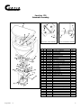
Tractor Cab, Inc.
FAST-CAST SERIES
SPREADERS
INSTALLATION & OWNER’S MANUAL
Covers: Fast-Cast 175, 2000, 3000, 4000
Table of Contents
Pp. 1-3
Safety Precautions & Warnings
Wiring Instructions............................................. Pp. 4,5
Operating Instructions....................................... Pp. 6,7
Fast-Cast 175 Schematic Assembly.................. P. 8
Fast-Cast 175 Assembly & Wiring Instructions..Pp. 9-11
Drop Utility Mount Schematic Assembly............ P. 12
3-Point Hitch Mount Schematic......................... P. 13
Fast-Cast 2000 Schematic Assembly................ P. 14
Fast-Cast 3000 Schematic Assembly................ P. 15
Drive Assembly Schematic................................ P. 16
Fast-Cast 4000 Schematic Assembly................ P. 17
Swing Away-Pivot Mount Schematic................. P. 18-20
Troubleshooting................................................ P. 21
Spreader Maintenance...................................... P. 22
Fast-Cast 175
Application: SALT, DEICERS, FREE FLOWING MATERIAL
Fast-Cast 2000
Application: SALT, DEICERS, FREE FLOWING MATERIAL
Fast-Cast 3000
Application: SALT, DEICERS, FREE FLOWING MATERIAL
Fast-Cast 4000
Application: 100% SAND, SAND/SALT MIX
Curtis Tractor Cab, Inc. and/or Curtis International, Inc. reserves the right to change product design or specifications
without notice or liability. Curtis snowplows and truck equipment should only be used on vehicles equipped with the
manufacturer’s snowplow preparation package. Snowplowing without the original snowplow preparation package may
damage your vehicle and the added weight of the equipment may impair the operation and control of the vehicle.
CURTIS PRODUCTS ARE PROTECTED UNDER THE FOLLOWING PATENT NUMBER: 5815956. OTHER PATENTS PENDING
1160
TRACTOR CAB INC.
111 Higgins Street
Worcester, MA 01606
Tel: (800) 343-7676
Fax: (800) 876-9104
WARNING
Safety
CAUTION
Before attempting any procedure in this book, these safety instructions must be read
and understood by all workers who have any part in the preparation or use of this
equipment.
For your safety warning and information decals have been placed on this product to remind the
operator of safety precautions. If anything happens to mark or destroy the decals, please
request new ones.
WARNING
August 2001
Remember most accidents are preventable and caused by
human error. Exercising of care and precautions must be
observed to prevent the possibility of injury to
operator or others!
WARNING
Never operate equipment when under the influence of alcohol,
drugs, or medication that might alter your judgment and/or
reaction time.
WARNING
Before working with the spreader, secure all loose fitting clothing
and unrestrained hair.
WARNING
Always wear safety glasses with side shields when working metal
against metal. Failure to do this could result in serious injury to the
eyes or other parts of the body.
1161
1
TRACTOR CAB INC.
Safety
(continued)
WARNING
CAUTION
Never allow children to operate or climb on equipment.
Never weld or grind on equipment without having a fire extinguisher available.
Always check areas to be spread to be sure no hazardous conditions or substances are in the area.
Always inspect unit for defects: broken, worn or bent parts, weakened areas on spreader or mount.
WARNING
Always shut off vehicle and power source before attempting to
attach or detach or service spreader unit. Be sure vehicle/power
source is properly braked or chocked.
WARNING
Always make sure personnel are clear of areas of danger
when using equipment.
WARNING
Always keep hands, feet, and clothing away from
power-driven parts.
Remember it is the owner’s responsibility to communicate information on safe usage and proper
maintenance of all equipment.
August 2001
1162
2
TRACTOR CAB INC.
Safety Precautions
WARNING
CAUTION
August 2001
Never exceed 45 m.p.h. when loaded spreader is attached to
vehicle. Braking distances may be reduced and handling
characteristics may be impaired at speeds above 45 m.p.h.
Never use wet materials, or materials with foreign debris in the
Fast-Cast 175, Fast-Cast 2000, and Fast-Cast 3000. These units
are designed to handle dry, clean, free-flowing material.
Note: Can not spread water softner salt.
CAUTION
Never leave material in hopper for long periods of time. Be aware
that all ice melters are hygroscopic and will attract atmospheric
moisture and harden up.
WARNING
Always inspect pins, and latches whenever attaching or detaching
spreader, and before traveling.
WARNING
Inspect the unit periodically for defects. Parts that are broken,
missing, or worn out must be replaced immediately. The unit, or
any part of it should not be altered without prior written permission
from the manufacturer.
1163
3
TRACTOR CAB INC.
Wiring Instructions
STEP 1: TAKE HARNESS ASSEY.AND ROUTE FROM THE REAR OF THE VEHICLE TO THE FRONT. ROUTE HARNESS
ALONG FRAME AND ATTACH TO FRAME HOLES AND FRAME SUPPORTS. IT IS NOT RECOMMENDED TO ATTACH TO
FUEL OR BRAKE LINES FOR OBVIOUS REASONS. DO NOT ROUTE CLOSE TO EXHAUST SYSTEM OR ENGINE, EVEN
THOUGH CURTIS USES HIGH TEMPRETURE WIRING IT STILL COULD MELT UNDER EXTREME HEAT AND
SHORT THE SPREADER ELECTRICAL SYSTEM AS WELL AS THE VEHICLE ELECTRICAL SYSTEM.
STEP 2: MOUNT REAR PLUG ON BUMPER USING SUPPLIED BOLTS, LOCATE TOWARDS THE CENTER OF THE BUMPER
TO REDUCE THE AMOUNT OF DEBRIS THE TIRES WILL THROW TO THE REAR. IMPORTANT–APPLY A SMALL
AMOUNT OF DIAELECTRIC GREASE TO THE PLUG.
STEP 3: SECURE HARNESS FROM THE REAR TO THE FRONT USING HEAVY DUTY TY-WRAPS OR FRAME CLIPS ALONG
THE FRAME AND LIGHTER DUTY TY-WRAPS EVERYWHERE ELSE.
STEP 4: LAYOUT HARNESS PORTION THAT CONNECTS TO THE BATTERY ALONG THE FIRE WALL AND FENDER
WELL. DO NOT CONNECT POWER LEADS TO BATTERY YET. DRILL A 3/4'' HOLE IN THE FIRE WALL FOR THE
CONTROL PORTION OF THE HARNESS AND ROUTE CONNECTOR AND HARNESS THROUGH HOLE. BE SURE TO
CHECK THE AREA ON THE OTHER SIDE OF THE FIRE WALL TO MAKE SURE YOU ARE NOT GOING TO DRILL INTO
THE VEHICLE HARNESS OR A CONTROL MODULE. GENERALLY YOU CAN DRILL ON EITHER SIDE OF THE STEERING
WHEEL FOR A GOOD LOCATION.
STEP 4A: (FAST-CAST 4000) THE POWER HARNESS FROM CONTROL BOX TO BATTERY WILL NEED TO BE ROUTED
FROM THE INSIDE OF THE CAB TO THE BATTERY – THIS RESULTS FROM THE LARGE HIGH AMPERAGE
CONNECTOR. ROUTE LEADS WITH LUGS TO BATTERY – DO NOT CONNECT POWER AT THIS TIME.
STEP 5: CONNECT HARNESS TO THE BACK OF THE CONTROLLER AND MOUNT TO A SUITABLE
LOCATION.****(NOTE)****YOU MAY WANT TO CONTACT CUSTOMER BEFORE MOUNTING CONTROLLER, SOME
PREFER NOT TO HAVE HOLES DRILLED INTO THE DASHBOARD. TY-WRAP LOOSE CONTROLLER HARNESS AND MOVE
TO THE ENGINE COMPARTMENT.
STEP 6: CONNECT POWER LEADS TO THE BATTERY: RED+ POSITIVE, BLACK - NEGATIVE, ALWAYS CONNECT TO
THE PRIMARY BATTERY IF USING A DUAL BATTERY SYSTEM, SECURE LOOSE LOOM TO ANY OTHER LARGE OR
MEDIUM VEHICLE HARNESS WITH MEDIUM DUTY TY-WRAPS THIS WILL SECURE WIRING HARNESS.
STEP 7: INSTALL IGNITION WIRE TO AN AUXILIARY CIRCUIT THAT IS HOT WHEN THE IGNITION KEY IS TURNED TO
ON POSITION. THIS WIRE IS 60'' LONG AND HAS A FEMALE TERMINAL ATTACHED TO IT. THIS WIRE WILL PLUG
INTO BACK OF CONTROLLER. THIS WIRE MUST BE INSTALLED IN ORDER FOR CONTROLLER TO WORK.
STEP 8: PUSH THE ON/OFF BUTTON ON THE CONTROLLER TO CHECK FOR POWER, WHEN THAT HAS BEEN
CONFIRMED TURN POWER OFF. THE ELECTRICAL PORTION OF THE INSTALLATION IS COMPLETE.
NOTE: IF ADDING AN INLINE FUSE, USE A 35 AMP SLOW BLOW FUSE (FAST-CAST 2000 AND FAST-CAST 3000
ONLY), AND USE A 60 AMP SLOW BLOW FUSE FOR FAST-CAST 4000 ONLY.
August 2001
1164
4
TRACTOR CAB INC.
Control Parts / Wiring Schematic
Fast-Cast 2000 / Fast-Cast 3000
Connector
(rubber molded type)
Black Lead (-) Neg
+ POS
Red
- NEG
Black
Red Lead (+) Pos
Battery
Controller
Connector
(rubber molded type)
Battery
Fast-Cast 4000
(+) Pos
Red
(-) Neg
Black
To
Controller
From
Controller
Special Notes:
1. All external connections must have dielectric grease.
2. Read lead labels before attaching to power source or ground.
3. No other devices may be spliced into wiring harness.
4. Any repairs to wiring harness must be done with heat shrink butt connectors.
5. If inline fuse is installed, use a 35 amp slow blow (Fast-Cast 2000 and Fast-Cast 3000), and use a 60 amp slow blow fuse for Fast-Cast 4000 only.
Item No.
August 2001
1165
Part No.
1CS1P39
1CS1P38
1CS1P35
1CS1P36
1CS1P32
1CS4P25
1CS4P26
1CS4P27
1CS1P52
1CS1P40
Description
Male Splice Cord - 18”
Female Splice Cord - 18”
Wiring Harness - 24’
Dust Cover
Controller
Fast-Cast 4000 Controller
Fast-Cast 4000 Wiring Harness - 25'
Control Power Cable
Diaelectric Grease - 1 1/2 oz.
60'' Ignition Wire
Qty.
1
1
1
1
1
1
1
1
1
1
5
TRACTOR CAB INC.
Operating the Spreader
Preparation
Caution – Sweep area clear of foreign objects or obstacles that could cause personal injury. Keep
other persons, children, or animals out of the area to be spread.
Spreader Loading
Warning – Do not overload vehicle. Use chart below to calculate weight of material. Weights of
material are an average for dry materials.
Material
Rock Salt
Coarse Sand
Weight Per Cubic Ft.
35-40 lbs.
85-95 lbs.
• Maximum weight of material for the Fast-Cast 175, 180 lbs., the Fast-Cast 2000, 300 lbs.,
the Fast-Cast 3000, 600 lbs., and the Fast-Cast 4000, 750 lbs.
• Be sure to comply with manufacturer’s maximum gross vehicle weight ratings.
• Warning – Never leave materials in hopper for long periods of time as salt is hygroscopic and will
attract atmospheric moisture and harden up. When spreading sand mix with 20% ice melter to
prevent the material from freezing.
Spreading Tips
• Never exceed 10 m.p.h. when spreading.
• For a wider pass, increase spinner speed.
• For a heavier pass, drive slower, or increase auger speed (Fast-Cast 4000).
• Never operate spreader around pedestrians.
• Spread ice melters with the storm to prevent unmanageable levels of ice.
• Calculate spread pattern when near vegetation.
August 2001
1166
6
TRACTOR CAB INC.
Operating the Spreader (cont.)
Spreader Operation
Fast-Cast 2000 / Fast-Cast 3000
•
•
•
•
•
The variable speed controller has finger-tip dial action, digital system status with warning protection.
To start, press power switch on controller and spreader will accelerate to speed set on dial.
To stop, press power switch on controller to off position.
Adjust speed of spinner by using dial on right side of controller.
If audible beeping occurs, read the sequence and refer to page 21.
Fast-Cast 4000
• The Dual Variable Speed Control has dual finger-tip dials for maximum performance, digital system
status with warning protection and built-in Vibrator Switch.
• To start, press power switch on controller and spreader will accelerate to speed set on spinner and
auger dials.
• To stop, press power switch on controller to off position.
• Speed of auger and spinner may be adjusted separately to get desired flow and spread distance
from spreader.
• The Vibrator Switch is needed for dense material or to increase the flow to the Auger. This eliminates
bridging of material.
• A Material Baffle (Part #1CS4P19) has been installed in your spreader to stop fine material from
free-flowing. If using dense or damp material, or if more flow is desired, remove Material Baffle.
However, it is recommended that the Material Baffle remain inplace if using bulk salt.
• It is important that the Inverted Vee (Part #1CS4P18) not be removed except when servicing.
• If audible beeping occurs, read display to identify problem. If display reads “OL” (overload) or
“OH” (overheat). Shut controller down and carefully clear jammed auger. If display reads “E1“ this
means there is a dead short in system. Do not use until problem is corrected. If display reads “E 0”
this means that the motor is not getting any power. Check all connections. If display reads “LB” the
vehicle battery is extremely low and could damage system.
• If there are any problems while operating the spreader, refer to Troubleshooting Guide
on page 21.
August 2001
1167
7
TRACTOR CAB INC.
Fast-Cast 175
Schematic Assembly
August 2001
1168
GATE DECK - CABLE ASSEMBLY
Item No.
Part No.
1CS1P8
1CS1P9
1CS1P41
1SM1P3
1SM1P2
1CS2P15
1CS1P53
1CS1P25
1CS1P24
1CS1P30
1CS1P27
1CS1P28
1SM5P1
1CS1P46
1CS2P21
1CS1P7
1CS1P18
1CS1P51
1CS2P2
1CS2P16
1CS2P17
1CS2P3
1CS2P7
1CS2P23
1CS2P10
1CS2P20
1CS2P11
1CS2P12
1CS2P13
1CS2P14
1CS2P18
1CS2P19
1CS2P22
1CS2P24
MOTOR - TRANSMISSION ASSEMBLY
Description
3/8'' - 16'' x 1'' Hex Bolt
3/8'' - Locknut
3/8'' Flat Washer
2-5/16' Hair Pin Clip
5/8'' x 5-1/2'' Hitch Pin
3/8'' Fender Washer
Transmission
1/4'' - 20 x 3/4'' Stainless Hex Bolt
5/16'' - 18 x 1/2'' Hex Bolt
1/4'' Stainless Lock Washer
#10 - 32 x 5/8'' Hex Machine Screw
#10 - 32 Lockwasher
5/16'' Lock Nut
5/16'' Lockwasher
5/16'' Flatwasher
5/16'' - 18 Hex Nut
10'' Steel Spinner
Motor Drive Coupler
T-Handle Cable - 10'
Bulkhead Cable Fitting
5/16'' - 16 x 3/4'' Bolt w/hole
Main Frame
Agitator Spring
Weather Cover
Motor 12 Volt DC
Hopper
Cord Restraint
Bottom Cover Assembly
Gate Slide
Gate Track
Foam Seal 40''
5/16'' - 18 x 1'' Hex Bolt S.S.
Gate Deck
Gate Slide Stop Pin
Qty.
10
10
2
1
1
4
1
4
1
4
2
2
6
1
4
1
1
1
1
1
1
1
1
1
1
1
1
1
1
1
1
6
1
1
8
TRACTOR CAB INC.
Fast-Cast 175 Assembly Instructions
1. Install foam tape on bottom of motor enclosure/frame assembly.
2. Bolt bottom cover assembly on to motor enclosure. Make sure 2'' square tube faces the rear.
3. Attach bulkhead cable fitting onto cable outer jacket. Using pliers to hold the cable, thread fitting onto jacket with a
wrench. Be careful not to bend or kink cable. Important: To maximize the life of the cable and prevent corrosion, apply
a small amount of oil to the inner cable.
3a. If you need to reduce the cable length, remove inner cable by twisting the T-handle counter clockwise and pull wire out
of cable jacket, and trim to desired length. Make note of the amount of wire that extends beyond outer jacket. You will
need to maintain this length for proper operation.
3b. Optional* You may run the cable through either the left or right side of rear spreader frame. There are two holes
located along the back side of ther rear upper horizontal support. This would be used to keep cable routed away from
other equipment or to take up any slack in cable. Also this will keep cable from being kinked if mounted on a pickup
truck.
4. Attach cable assembly to the side and insert fitting into rear gate deck hole. Make sure you have the first jam hex nut
threaded onto the fitting.
4a. Once cable is inserted through rear gate deck, slide star washer and second jam nut over cable fitting. Leave these
loose for now.
5. Locate special 5/16'' hex bolt with a small hole drilled in it. Insert bolt through slide tab. The hole in bolt must be as
close to being in line with the cable as possible.
6. Rotate hex bolt until hole aligns with the cable. Insert cable through hole. Thread lock washer and hex nut on. Do not
tighten yet.
7. Make sure gate is at full close and that the cable is at full close. Once this is done, tighten hex bolt on gate slide, then
tighten cable assembly on rear gate deck. This will insure that the gate slide can seal off hopper 100%.
8. Test gate travel by pulling and pushing the T-handle. The cable assembly has a twist-lock feature. Turning clockwise
locks the gate into position, turning coutner clockwise allows gate to move back and forth.
9. Install nylon lid.
10. Mount spreader into a 2'' receiver type tube, align holes on mount and spreader and install 4'' locking pin.
August 2001
1169
9
TRACTOR CAB INC.
Fast-Cast 175 Wiring Instructions
1. First, install switch at desired location. This will determine what your proper wire length is to be.
2. Run spreader/vehicle harness from the rear of vehicle to switch area. Remove approx. 3'' of the black outer jacket
exposing two single leads (red and black), strip a 1/4'' off each lead. Crimp 1/4'' female connector on red lead and
crimp the butt connector to the black lead. Place the female spade/red wire to the on/off switch and leave the black
wire for the next step.
3. Route the power harness from the battery to the switch; this will determine your proper length to cut wires. Repeat step
#2 regarding cable jacketing and connection points to the switch and butt connector.
4. Install an inline 30 amp. fuse on the positive (red) lead from the battery to the switch. Locate an easily accessible place,
out of the elements, for the fuse and remove approx. 3'' of the black outer jacket exposing two single leads (red and
black). Cut the red lead in half and strip a 1/4'' off each lead. Insert into the fuse connector and crimp. Insert 30 amp.
blade fuse into connector.
5. At the battery end of the power harness, remove 8'' of the black outer jacket exposing two single leads (red and black).
Strip 1/4'' off each lead. Crimp a 3/8'' lug terminal to each lead and attach the red lead to the positive side of the
battery and the black lead to the negative side of the battery.
6. Install rubber weatherproof boot on switch before finishing installation.
August 2001
1170
10
TRACTOR CAB INC.
Fast-Cast 175
Wiring Schematic
(–) Neg. Black
(+) Pos.Red
(+) Pos.Red
+
12 VOLT
BATTERY
–
(–) Neg. Black
Item No.
August 2001
1171
Part No.
1CS2P25
1CS2P26
1CS1P52
1CS2P27
1CS2P28
1CS2P29
1CS2P30
1CS2P31
1CS2P10
1CS2P32
1CS2P33
1CS2P34
1CS2P35
Description
On/Off Switch
Butt Connector
Dielectric Grease
20' Vehicle Harness
10' Battery Harness
Rubber Switch Boot
Spreader Splice Cord - 10''
Harness Splice Cord - 10''
Motor 12 Volt DC
30 Amp Fuse
Fuse Holder
Ring Terminal
Spade Connector
Qty.
1
1
1
1
1
1
1
1
1
1
1
2
2
11
TRACTOR CAB INC.
Drop Utility Mount
Schematic Assembly
Maximum Load Weight Not To Exceed 240 lbs. Gross
Item No.
August 2001
1172
Part No.
1SM3P4
1CS1P11
1CS1P8
1CS1P9
1CS1P41
1SM1P3
1SM1P2
1SM4P10
1CS2P15
1SM4P2
1SM4P3
1SM4P4
1SM4P5
1SM4P9
1SM4P6
1SM4P7
1SM4P8
Description
1/2’’ Flat Washer
1/2’’-Lock Nut
3/8’’-16x1 Hex Bolt
3/8’’-Lock Nut
3/8’’ Flat Washer
2 - 5/16'' Hair Pin Clip
5/8'' x 5-1/2'' Hitch Pin
1/2'' - 13 x 2'' Hex Bolt
3/8'' Fender Washer
3/8'' - 16 x 2 Truss Bolt Full Thread
3/8'' - 16 Hex Nut
3/8'' - 16 x 5'' Hex Bolt
2'' Rubber Stopper
Mounting Rail
Drop Mount Weldment
Mounting Rail Hat Section
Mule Adapter
Qty.
2
2
2
8
9
2
2
2
8
8
2
1
1
2
1
2
1
12
TRACTOR CAB INC.
3-Point Mount
Schematic Assembly
Item No.
August 2001
1173
Part No.
1SM1P7
1SM1P3
1SM1P2
1SM1P6
1SM1P1
Description
5/16” Linch Pin
2-5/16” Hairpin Clip
5/8” x 5-1/2” Hitch Pin
7/8” x 5-1/2” Lift Arm Pin
3-Point Frame
Qty.
2
1
1
2
1
13
TRACTOR CAB INC.
Fast-Cast 2000
Schematic Assembly
Item No.
Optional Mount
August 2001
1174
Part No.
1CS1P10
1CS1P11
1CS1P8
1CS1P9
1CS1P41
1CS1P2
1CS1P42
1CS1P12
1CS1P5
1CS1P6
1CS1P3
1CS1P1
1CS1P4
1CS1P46
1CS1P7
1CS1P47
1CS1P48
1CS1P49
Description
1/2’’-13 x 1 1/2’’ Hexbolt
1/2’’-Lock Nut
3/8’’-16x1 Hex Bolt
3/8’’-Lock Nut
3/8’’ Flat Washer
Flexible Draw Latch
Stainless Throat Liner
Deflector 20''
Throat Clamp
5/16’’-18x1 1/4’’ Stainless Pan Head Phillips Bolt
Hopper
Lid W/Latches
Main Frame
5/16’’ lock washer
5/16’’-Hex Nut
3/8’’ S/S Washer
Latch Keeper
Complete Drive Assembly
1SM2P1
1SM1P2
1SM1P3
2’’ Receiver Hitch
5/8'' x 5-1/2'' Hitch Pin
2 - 5/16'' Hair Pin Clip
Qty.
4
4
8
8
2
2
1
1
1
2
1
1
1
2
4
2
2
1
1
1
1
14
TRACTOR CAB INC.
Fast-Cast 3000
Schematic Assembly
August 2001
Item No.
1175
Part No.
1CS3P1
1CS1P11
1CS1P8
1CS1P9
1CS1P41
1CS3P2
1CS3P3
1CS1P2
1CS1P42
1CS1P12
1CS3P4
1CS3P5
1CS1P5
1CS1P6
1CS1P46
1CS1P7
1CS1P47
1CS1P48
1CS3P6
Description
1/2’’-13x1’’ Hex Bolt
1/2’’-Locknut
3/8’’-16 x 1’’ Hex Bolt
3/8’’-Locknut
3/8’’ -Flat Washer
Hopper
Lid W/Latches
Flexible Draw Latch
Stainless Throat Liner
Deflector - 20’’
Main Frame
Spinner Guard
Throat Clamp
5/16’’-18 x 1 1/4’’ Stainless Panhead Phillips Bolt
5/16’’ -Lock Washer
5/16’’ -Hex Nut
3/8’’ -S.S. Washer
Latch Keeper
Complete Drive Assembly
Qty.
4
4
12
12
2
1
1
2
1
1
1
1
1
2
2
2
2
2
1
15
TRACTOR CAB INC.
Complete Drive Assembly Schematic
Item No.
August 2001
1176
Part No.
1CS1P16
1CS1P53
1CS1P17
1CS1P13
1CS3P7
1CS1P21
1CS1P19
1CS1P22
1CS1P29
1CS1P25
1CS1P24
1CS1P30
1CS1P27
1CS1P28
1CS1P23
1CS1P18
1CS1P51
Description
Motor 12 Volt DC
Transmission
Motor Cover
Drive Enclosure
Fast-Cast 3000 Power Cable
Fast-Cast 2000 Power Cable
Auger
Cord Restraint
3/16’’ Aluminum Rivet
1/4’’-20 x 3/4’’ Hex Bolt Stainless
5/16''-18 x 1/2’’ Hex Bolt
1/4’’ Stainless Lock Washer
#10-32 x 5/8’’ Cap Screw
#10 Lock Washer
5/16’’-18 x 3/8’’ Set Screw
10’’ Steel Spinner
Motor Drive Coupler
Qty.
1
1
1
1
1
1
1
1
6
4
1
4
2
2
1
1
1
16
TRACTOR CAB INC.
Fast-Cast 4000
Schematic Assembly
Item No.
Part No.
1CS1P8
1CS4P1
1CS1P9
1CS1P41
1CS1P2
1CS1P22
1CS1P29
1CS1P25
1CS1P24
1CS1P30
1CS1P27
1CS1P28
1CS1P6
1CS1P23
1CS1P46
1CS4P2
1CS1P7
1CS1P47
1CS4P3
1CS1P48
1CS4P4
August 2001 1177
Description
3/8-16x1” Hex Bolt
3/8-16x1-1/2” Hex Bolt
3/8-16 Lock Nut
3/8” Flat Washer
Flexible Draw Latch
Cord Strain Relief
3/16'' Aluminum Rivit
1/4’’-20x1’’ SS Hex Bolt
5/16-18x1/2’’ Hex Bolt
1/4'' Stainless Lock Washer
10/32x5/8’’ Cap Screw
10/32 Lock Washer
5/16-18x1’’ Pan Head SS Bolt
5/16-18x3/8’’ Set Screw
5/16’’ Lock Washer
3/8’’-16x2’’ Hex Bolt
5/16’’ Hex Nut
3/8’’ SS Flat Washer
DC-80 Vibrator
Latch Keeper
12’’ Steel Spinner
Qty.
8
4
12
2
2
2
12
20
1
8
4
4
2
2
2
4
2
6
1
2
1
Item No.
Part No.
1CS1P51
1CS4P5
1CS4P6
1CS4P7
1CS4P8
1CS4P9
1CS4P10
1CS4P11
1CS4P12
1CS4P13
1CS4P14
1CS4P15
1CS4P16
1CS4P17
1CS4P18
1CS4P19
1CS4P20
1CS4P21
1CS4P22
1CS4P23
1CS4P24
Description
Motor Trans Coupler
Hopper
Lid
Auger
Spinner Transmission
Auger Transmission
Spinner Motor
Auger Motor
Power cord-48''
Frame
Trim Ring
Right Hand Motor Cover
Left Hand Motor Cover
Plastic Deflector
Inverted V-Support
Material Baffle
Chute
Auger Shaft Bearing
3/16’’ Rivet, Long
Top Screen
Inverted V-Mount Brkt
Qty.
2
1
1
1
1
1
1
1
1
1
1
1
1
1
1
1
1
1
2
1
1
17
TRACTOR CAB INC.
Swing Away – Pivot Mount
Schematic Assembly
NOTE:
When installing a FastCast 4000 or if any
movement is noted with
Rail Brackets due to
weakened or altered conditions of pick-up bed,
drill & bolt thru prepunched Rail Brackets to
assure firm mounting.
Item No.
August 2001
Part No.
1CS1P10
1SM3P4
1CS1P11
1CS1P8
1CS4P1
1CS1P9
1CS1P41
1SM5P1
1SM5P2
1SM5P3
1SM5P4
1SM5P5
1178
Description
1/2” 13 x 1 1/2” Hex Bolt
1/2” Flat Washer
1/2” Lock Nut
3/8” 16 x 1” Hex Bolt
3/8” 16 x 1 1/2” Hex Bolt
3/8” Lock Nut
3/8” Flat Washer
5/16” Lock Nut
5/16” 18 x 2” Hex Bolt
1/2” Toggle
1/2” 13 x 4” Hex Bolt Full Thread
1/2” 13 x 1 1/4” Hex Bolt
Qty.
2
7
5
16
13
29
9
1
1
2
2
3
Item No.
Part No.
1SM5P6
1SM5P7
1SM5P8
1SM5P9
1SM5P10
1SM5P11
1SM5P12
1SM5P13
1SM5P14
1SM5P15
1SM5P16
1SM5P17
Description
1/2” 13 x 3” Hex Bolt Full Thread
Bed Rail Bracket Right
Bed Rail Bracket Left
Pivot Tube Assembly
Angle Top
Pivot/ Bumper Bracket
Latch /Bumper Bracket
Pivot Channel Assembly
Latch Channel Assembly
Rubber Tip Protector
1/8” x 2-1/16” Hair Pin Clip
Latch Bar
Qty.
4
1
1
1
1
1
1
2
2
4
2
1
18
TRACTOR CAB INC.
Swing Away - Pivot Mount
Installation Instructions
Step 1. Insert upper & lower pivot rails into main frame of
spreader. Line up the pre-punched holes on the pivot
rail with the main frame, then bolt together. Holes are
pre-determined and can be relocated if spreader is
not centered on vehicle.
Step 2. Locate top bed rail mounting brackets and set on top
of pickup bed rails; Center by moving out towards the
bumper. Maintain a minimum of 2” clearance between
tailgate and spreader.
Step 3. Locate left & right bumper brackets. The left side or
the pivot side will have a two piece system that will
act as the hinge for the spreader. (See fig. D) The
right side will have a two-piece system that will be the
latching side. (See fig. H). Attach pivot tube and latch
bar to the bumper plates using the posts as centering
guides. Line up with the bed rail brackets. Be sure
that the tailgate will open before locating any of these
brackets permanently. Make sure bumper brackets
are parallel to the lower main frame so that everything
will be straight. After aligning all pieces, mark & drill
holes using the bumper plates as a guide. (As seen in
Fig. A) Once holes have been drilled, bolt securely to
bumper. Note: Use a minimum of 3 holes.
Step 4. Locate toggle bolt assembly and install on left and
right upper bed rail brackets as seen in (Fig. B).
Position toggle bolt (Fig. C) to keep in position while
tightening. Pull up on the bracket to keep a slight
amount of pressure on the toggle bolt. * NOTE *::
When tightening toggle bolt assembly, do not exceed
30 foot pounds of torque, or you may damage toggle
assembly. Take the two 3” full threaded bolts and
screw into bottom of bed rail brackets. Use rubber tip
protectors on bolt end as seen in (Fig. E). Torque
bolts down using a hand ratchet only - you may also
want to use a small amount of blue removable thread
locker. Do this only as a final assembly once you
have a proper tailgate clearance established.
Step 5. Now that the lower bumper brackets and upper bed
rail brackets are mounted, you will now need to check
both the pivot tube assembly and latch bar to see if
these need to be cut down. Due to the variety of truck
bumpers, bed rail heights, etc. We made these two
parts intentionally too long. On the pivot side you will
need to align the top of the pivot tube hole to the left
side bed rail bracket hole. Trim off the amount needed with a cut off saw.
Step 6. Put this piece aside for now. Now that you have the
pivot side assembly cut to length, mount spreader
August 2001
1179
main frame assembly to truck. With an assistant,
place pivot side of spreader on truck. Take pivot tube
assembly and insert through pivot rails to the bumper
plate locator tube. Take and bolt the upper pivot tube
assembly to the bed rail bracket. (Make sure bed rail
bracket is secure) Swing spreader until both support
pads on lower main frame rail are completely on the
bumper. Drill a 5/16” hole, (as seen in Fig. D) and bolt
lower portion of pivot tube assembly. This will now
complete pivot side installation.
Step 7. The latching side will be done the same way, except
that you will need to mount the locator bracket to the
right side bed rail bracket (see Fig F, G, H). Once you
have completed, trim flush with the top of the locator
bracket. After cutting bar to proper length, drill a 1/2”
hole in mounting bar. Bolt the upper portion and the
lower portion of the latching bar.
Step 8. Locate latching rails and insert into spreader main
frame, position the latch rails so they are latched to
the latching bar. Center latching bar in the pocket of
the end of the latch rail. (see Fig. F) This will insure
proper latching when closing spreader.
Step 9. Using an assistant or a large vice grip to insure rails
do not move, drill three 3/8” holes using the prepunched holes as a guide. Repeat this process for
the lower rail also. Bolt together. This completes the
latch side of the pivot mount.
Step 10. Drill four more 3/8” holes as seen in (Fig I) to stiffen
the whole frame/rail system. Bolt together. This will
insure minimum frame deflection under extreme load
conditions.
Step 11. Make sure spreader is level and clear from the tailgate when closed. You can make minor adjustments
by loosening the bed rail brackets (one at a time) and
trimming the unit out. Also at this time you may want
to apply a small amount of removable thread locker to
insure the bolts stay secure.
Step 12. Lube zerk fittings on pivot tubes.
Step 13. IMPORTANT: When installing a Fast-Cast 4000 or if
any movement is noticed with the bed rail brackets
due to weakness or altered conditions of pickup bed,
drill and bolt thru the pre-punched holes located on
the sides of the bed rail brackets and bolt securely.
Step 14. After first use tighten all nuts and bolts on mount
and spreader.
19
Swing Away - Pivot Mount Installation Schematic
TRACTOR CAB INC.
Fig. A
Fig. B
Fig. C
Fig. D
Fig. E
Fig. F
Fig. G
Fig. H
Fig. I
DRILL
DRILL
DRILL
August 2001
1180
20
TRACTOR CAB INC.
Troubleshooting
Whenever service is necessary, your local dealer knows your Curtis Spreader best. Take your Curtis
Spreader to your local dealer for any maintenance or service needs on your unit. If this is not
possible, the Troubleshooting Guide below may assist you in identifying the problem.
Warning: First read all warning instructions and safety messages before servicing your spreader.
Preliminary Checks
• Be sure all electrical connections are tight and clean.
• Be sure nothing is jammed in the hopper.
PROBLEM
Motor doesn’t run.
Shut down.
POSSIBLE CAUSE
Loose electrical connections.
Check all connections.
Blown Fuse.
Replace fuse.
Motor Seized.
Replace motor.
Jammed auger.
Carefully clear jammed material.
Poor electrical connections.
Clean or replace connectors.
Use dielectric grease.
Electrical short.
Controller Bad.
Material will not feed.
Replace controller.
No material in hopper.
Fill hopper.
Fill hopper.
Wet material.
Replace with dry material.
Frozen or coarse material.
Replace material.
Spinner not turning.
Check drive assembly.
Tighten locking bolt on the side of the auger. There
Tighten
locking bolt
sideshaft.
of the
auger.
is a flat machined
onon
thethe
driver
Align
the
There is a flat machined on the driver shaft.
auger
with
this
flat
and
tighten
the
bolt.
Align the auger with this flat and tighten the bolt.
Replace vibrator
ERROR FLASH CODES
Repeating Sequence
Status
Short-Short-Short
Open circuit in spreader motor circuit
Short-Short-Long
Short-Long-Short
Short circuit in spread motor circuit
Low battery
Short-Long-Long
Jammed Hopper
Long-Short-Short
Long-Short-Long
Overheated
Overload in spreader motor circuit
1181
Check electrical connections.
Check for bare wires.
Controller Bad.
Auger loose on shaft.
August 2001
SOLUTION
21
TRACTOR CAB INC.
SPREADER MAINTENANCE
• WARNING – When servicing is necessary, perform it in a protected area. Do not use power tools
in rain or snow because of danger of electrical shock or injury. Keep area well lighted. Use proper
tools. Keep the area of service clean to help avoid accidents.
• WARNING – Disconnect electricity to spreader before servicing.
• CAUTION – The controller is a solid state electronic unit and is not serviceable. Any attempt to
service will void warranty.
• CAUTION – There are no serviceable parts in our motor/transmission assembly. Any attempt to
service will void warranty.
• CAUTION – When replacing parts use only original manufacturer’s parts. Failure to do so will void
warranty.
• Use diaelectric grease on all electrical connections to prevent corrosion at the beginning and end of
the season and each time power plugs are disconnected.
• Wash unit after each use to prevent material build-up and corrosion.
• CAUTION – When pressure washing motor enclosure area stay at least 36'' away.
• Paint or oil all bare metal surfaces at the end of the season.
• Apply small amount of light oil to latches and hinges as needed.
• If motor cover is removed for any reason use silicone sealant to ensure weather
proofing of enclosure.
• Grease all bearings after 20 hours use (Fast-Cast 4000 only).
• After first use tighten all nuts and bolts on spreader and mount.
• Apply a small amount of oil on gate cable to prevent corrosion and maximize the cable life
(Fast-Cast 175 only).
August 2001
1182
22