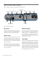
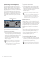
1
® Mbox Pro User Guide Legal Notices ©2012 Avid Technology, Inc., (“Avid”), all rights reserved. This guide may not be duplicated in whole or in part without the written permission of Avid. 003, 96 I/O, 96i I/O, 192 Digital I/O, 192 I/O, 888|24 I/O, 882|20 I/O, 1622 I/O, 24-Bit ADAT Bridge I/O, AudioSuite, Avid, Avid DNA, Avid Mojo, Avid Unity, Avid Unity ISIS, Avid Xpress, AVoption, Axiom, Beat Detective, Bomb Factory, Bruno, C|24, Command|8, Control|24, D-Command, D-Control, D-Fi, D-fx, D-Show, D-Verb, DAE, Digi 002, DigiBase, DigiDelivery, Digidesign, Digidesign Audio Engine, Digidesign Intelligent Noise Reduction, Digidesign TDM Bus, DigiDrive, , DigiTest, DigiTranslator, DINR, DV Toolkit, EditPack, Eleven, HD Core, HD Process, Hybrid, Impact, Interplay, LoFi, M-Audio, MachineControl, Maxim, Mbox, MediaComposer, MIDI I/O, MIX, MultiShell, Nitris, OMF, OMF Interchange, PRE, ProControl, Pro Tools, Pro Tools|HD, QuickPunch, Recti-Fi, Reel Tape, Reso, Reverb One, ReVibe, RTAS, Sibelius, Smack!, SoundReplacer, Sound Designer II, Strike, Structure, SYNC HD, SYNC I/O, Synchronic, TL Aggro, TL AutoPan, TL Drum Rehab, TL Everyphase, TL Fauxlder, TL In Tune, TL MasterMeter, TL Metro, TL Space, TL Utilities, Transfuser, Trillium Lane Labs, Vari-Fi, Velvet, X-Form, XMON and Xpand! are trademarks or registered trademarks of Avid Technology, Inc. All other trademarks are the property of their respective owners. Product features, specifications, system requirements, and availability are subject to change without notice. Guide Part Number 9329-65070-00 REV C 12/12 Documentation Feedback At Avid, we are always looking for ways to improve our documentation. If you have comments, corrections, or suggestions regarding our documentation, email us at [email protected]. Contents Chapter 1. Welcome to Mbox Pro . . . . . . . . . . . . . . . . . . . . . . . . . . . . . . . . . . . . . . . . . . . . . . . . . 1 Mbox Pro Features . . . . . . . . . . . . . . . . . . . . . . . . . . . . . . . . . . . . . . . . . . . . . . . . . . . . . . . 1 System Requirements and Compatibility . . . . . . . . . . . . . . . . . . . . . . . . . . . . . . . . . . . . . . . . 3 Conventions Used in This Guide . . . . . . . . . . . . . . . . . . . . . . . . . . . . . . . . . . . . . . . . . . . . . . 3 About www.avid.com . . . . . . . . . . . . . . . . . . . . . . . . . . . . . . . . . . . . . . . . . . . . . . . . . . . . . . 4 Chapter 2. Mbox Pro Hardware Overview . . . . . . . . . . . . . . . . . . . . . . . . . . . . . . . . . . . . . . . . . . 5 Mbox Pro Front Panel Features . . . . . . . . . . . . . . . . . . . . . . . . . . . . . . . . . . . . . . . . . . . . . . 5 Mbox Pro Back Panel Features . . . . . . . . . . . . . . . . . . . . . . . . . . . . . . . . . . . . . . . . . . . . . . 8 Chapter 3. Installing and Connecting Mbox Pro . . . . . . . . . . . . . . . . . . . . . . . . . . . . . . . . . . . . 11 Chapter 4. Making Studio Connections . . . . . . . . . . . . . . . . . . . . . . . . . . . . . . . . . . . . . . . . . . . 13 Connecting Outputs . . . . . . . . . . . . . . . . . . . . . . . . . . . . . . . . . . . . . . . . . . . . . . . . . . . . . . 13 Audio Inputs . . . . . . . . . . . . . . . . . . . . . . . . . . . . . . . . . . . . . . . . . . . . . . . . . . . . . . . . . . . 15 Connecting a Microphone . . . . . . . . . . . . . . . . . . . . . . . . . . . . . . . . . . . . . . . . . . . . . . . . . . 16 Connecting Instruments to the Mbox Pro . . . . . . . . . . . . . . . . . . . . . . . . . . . . . . . . . . . . . . . 18 Connecting Keyboards and Mixers . . . . . . . . . . . . . . . . . . . . . . . . . . . . . . . . . . . . . . . . . . . 19 Connecting Inserts . . . . . . . . . . . . . . . . . . . . . . . . . . . . . . . . . . . . . . . . . . . . . . . . . . . . . . . 19 Connecting Digital I/O . . . . . . . . . . . . . . . . . . . . . . . . . . . . . . . . . . . . . . . . . . . . . . . . . . . . 20 MIDI Connections . . . . . . . . . . . . . . . . . . . . . . . . . . . . . . . . . . . . . . . . . . . . . . . . . . . . . . . 21 Word Clock . . . . . . . . . . . . . . . . . . . . . . . . . . . . . . . . . . . . . . . . . . . . . . . . . . . . . . . . . . . . 22 Using a Footswitch. . . . . . . . . . . . . . . . . . . . . . . . . . . . . . . . . . . . . . . . . . . . . . . . . . . . . . . 23 Chapter 5. Using the Driver Control Panel. . . . . . . . . . . . . . . . . . . . . . . . . . . . . . . . . . . . . . . . . 25 Setup . . . . . . . . . . . . . . . . . . . . . . . . . . . . . . . . . . . . . . . . . . . . . . . . . . . . . . . . . . . . . . . . 26 Flow . . . . . . . . . . . . . . . . . . . . . . . . . . . . . . . . . . . . . . . . . . . . . . . . . . . . . . . . . . . . . . . . . 31 About . . . . . . . . . . . . . . . . . . . . . . . . . . . . . . . . . . . . . . . . . . . . . . . . . . . . . . . . . . . . . . . . 32 Stereo Mix Section . . . . . . . . . . . . . . . . . . . . . . . . . . . . . . . . . . . . . . . . . . . . . . . . . . . . . . . 32 Presets . . . . . . . . . . . . . . . . . . . . . . . . . . . . . . . . . . . . . . . . . . . . . . . . . . . . . . . . . . . . . . . 38 Layouts . . . . . . . . . . . . . . . . . . . . . . . . . . . . . . . . . . . . . . . . . . . . . . . . . . . . . . . . . . . . . . . 38 Contents iii Chapter 6. Using the Multi Button . . . . . . . . . . . . . . . . . . . . . . . . . . . . . . . . . . . . . . . . . . . . . . . 41 Using the Multi Button . . . . . . . . . . . . . . . . . . . . . . . . . . . . . . . . . . . . . . . . . . . . . . . . . . . . 41 Press and Release Options . . . . . . . . . . . . . . . . . . . . . . . . . . . . . . . . . . . . . . . . . . . . . . . . 42 Press and Hold Options . . . . . . . . . . . . . . . . . . . . . . . . . . . . . . . . . . . . . . . . . . . . . . . . . . . 43 Hold Duration Options . . . . . . . . . . . . . . . . . . . . . . . . . . . . . . . . . . . . . . . . . . . . . . . . . . . . 43 Appendix A. Using CoreAudio- and ASIO-Compliant Applications . . . . . . . . . . . . . . . . . . . . 45 Configuring Mbox Pro for Third-Party Applications . . . . . . . . . . . . . . . . . . . . . . . . . . . . . . . 45 Configuring the Apple Sound Preferences . . . . . . . . . . . . . . . . . . . . . . . . . . . . . . . . . . . . . 45 Appendix B. Compliance Information . . . . . . . . . . . . . . . . . . . . . . . . . . . . . . . . . . . . . . . . . . . . 47 Environmental Compliance . . . . . . . . . . . . . . . . . . . . . . . . . . . . . . . . . . . . . . . . . . . . . . . . 47 EMC (Electromagnetic Compliance) . . . . . . . . . . . . . . . . . . . . . . . . . . . . . . . . . . . . . . . . . . 48 Safety Compliance . . . . . . . . . . . . . . . . . . . . . . . . . . . . . . . . . . . . . . . . . . . . . . . . . . . . . . 49 iv Avid Mbox Pro User Guide Chapter 1: Welcome to Mbox Pro Welcome to the Mbox® Pro FireWire audio and MIDI interface from Avid®. Mbox Pro provides your FireWire-equipped computer with six channels of analog audio input, six channels of analog audio output, two channels of S/PDIF digital audio input and output, MIDI and Word Clock I/O, and two front panel headphone outputs with independent level controls. Mbox Pro provides professional-quality mic preamps and 24-bit/192 kHz analog-to-digital and digital-toanalog converters. Mbox Pro integrates with Pro Tools® software, and is compatible with third-party audio and MIDI applications that support the CoreAudio (Mac) or ASIO (Windows) standard. Mbox Pro Features The Mbox Pro provides the following: Audio Inputs and Outputs Mbox Pro provides up to eight discrete channels of input and up to eight discrete channels of output, using the following analog and digital I/O: Analog Inputs • Two channels of analog audio input with high quality microphone preamps (inputs 1–2). Each input channel 1–2 provides: • 48v Phantom Power and inserts • Two XLR/TRS (Mic/DI) combo connectors on the front panel, and two 1/4-inch TRS Line connectors with switchable +4/-10 input level on the rear panel • Mic preamps feature a –20 dB pad and softlimit switch separately on each analog input channel • Mic/DI signal is adjusted by the Gain knob for each channel Chapter 1: Welcome to Mbox Pro 1 • Two additional channels of analog audio input with high quality microphone preamps. Each input channel 3–4 provides: MIDI • One MIDI In and one MIDI Out port, providing 16 channels of MIDI input and output • 48v Phantom Power and inserts • Analog input jacks include two XLR Mic connectors on the rear panel, and two 1/4inch TRS Line connectors with switchable +4/-10 input level also on the rear panel Other Capabilities and Specifications • Mic preamps feature a –20 dB pad and softlimit switch separately on each analog input channel • Low latency direct record monitoring • Mic signal is adjusted by the Gain knob for each channel • Two 1/4-inch (TRS) stereo headphone outputs (A and B) with independently adjustable level and routing controls • Two channels of analog audio input via RCA or 1/8-inch connectors (Aux 5/6). Each input channel provides: • Analog input jacks provide an unbalanced line input on either RCA connectors or a 1/8inch mini stereo connector (common for connecting most MP3 players) • Inputs are fully functioning inputs to Pro Tools as well as providing an alternate monitor source using the Speaker button Analog Outputs • Six balanced 1/4-inch TRS analog outputs, supporting line level outputs, multiple stereo monitors, or up to 5.1 surround monitoring • Insert jacks (1–4) for inserting external processing devices on input channels • 24-bit A/D and D/A converters, supporting sample rates of 44.1 kHz, 48 kHz, 88.2 kHz, 96 kHz, 176.4 kHz, and 192 kHz Digital I/O • Two channels of S/PDIF digital input and output. S/PDIF inputs are available independent of and in addition to analog inputs 1–6. S/PDIF outputs are always available in Pro Tools 2 Avid Mbox Pro User Guide • Front panel “Multi” button, assignable to a variety of common Pro Tools functions • On-board tuner • Control room functionality including front panel Dim/Mute, Mono and Speaker/Source switches • Footswitch jack for starting or stopping playback or punching in and out while recording • Multi-pin port (DB15 connection) that handles Word Clock, MIDI, and S/PDIF via included breakout cable System Requirements and Compatibility Conventions Used in This Guide Mbox Pro can be used with a qualified Windows or Mac computer running Pro Tools software 8.0.4 or higher. All of our guides use the following conventions to indicate menu choices and key commands: For Pro Tools installation instructions, see the Pro Tools Installation Guide. Mbox Pro can be also be used with a qualified Mac or Windows computer running any other Core Audio- or ASIO-compliant software. Mbox Pro hardware drivers must be installed before you can connect and use your Mbox Pro. For Mbox hardware drivers installation instructions, see Chapter 3, “Installing and Connecting Mbox Pro.” A DVD drive is required to use the Drivers Installer disc (included with your Pro Tools software package). Avid can only assure compatibility and provide support for hardware and software it has tested and approved. For complete system requirements and a list of qualified computers, operating systems, hard drives, and third-party devices, visit: www.avid.com/compatibility : Convention Action File > Save Choose Save from the File menu Control+N Hold down the Control key and press the N key Control-click Hold down the Control key and click the mouse button Right-click Click with the right mouse button The names of Commands, Options, and Settings that appear on-screen are in a different font. The following symbols are used to highlight important information: User Tips are helpful hints for getting the most from your system. Important Notices include information that could affect your data or the performance of your system. Shortcuts show you useful keyboard or mouse shortcuts. Cross References point to related sections in this guide and other Pro Tools guides. Chapter 1: Welcome to Mbox Pro 3 About www.avid.com The Avid website (www.avid.com) is your best online source for information to help you get the most out of your Pro Tools system. The following are just a few of the services and features available. Product Registration Register your purchase online. Support and Downloads Contact Avid Customer Success (technical support); download software updates and the latest online manuals; browse the Compatibility documents for system requirements; search the online Knowledge Base or join the worldwide Pro Tools community on the User Conference. Training and Education Study on your own using courses available online or find out how you can learn in a classroom setting at a certified Pro Tools training center. Products and Developers Learn about Avid products; download demo software or learn about our Development Partners and their plug-ins, applications, and hardware. News and Events Get the latest news from Avid or sign up for a Pro Tools demo. 4 Avid Mbox Pro User Guide Chapter 2: Mbox Pro Hardware Overview Mbox Pro Front Panel Features Figure 1 identifies controls, indicators, and input and output ports on the front panel on the Mbox Pro. Input combo jacks Gain/–20 dB Pad switch Headphones A and B Volume knob Dim/Mute Gain/–20 dB Pad switches switch Multi button Soft limit switches Soft limit switch Front/Back input source switch Front/Back input source switch 48V switch LED ladders (inputs 1 - 4) Power indicator LED Mono switch Headphone outputs Master Volume knob Speaker source select button Mic/Line input source button Figure 1. Mbox Pro front panel Input Combo Jacks (Mic/DI) These combination jacks (Mic/DI) provide XLR and 1/4-inch (TS) inputs for Input channels 1 and 2. Gain/–20 dB Pad Switches These knobs adjust the input gain levels of Mic/DI 1 and 2, or Mic 3 and 4. Turn the knob clockwise to increase gain, and counter-clockwise to decrease gain. If your input signal is too hot even with the Gain knob at a low setting, pull the Gain knob out to engage a “pad” that attenuates the signal by –20dB. Front/Rear Input Source Switches These buttons select the input source for input channels 1 and 2. When “out”, the front panel Mic/DI input is active; when “in” the back panel Line Input is active for that channel. Chapter 2: Mbox Pro Hardware Overview 5 Soft Limit Switch These switches engage a soft limiter on that channel, applying a smooth, overdriven tape-type limiter to strong input signals. Mic/Line Input Source Button These buttons select the input source for input channels 3 and 4. When “out”, the back panel Mic input is active; when “in” the back panel Line Input is active for that channel. LED Ladders (Inputs 1–4) These four 8-segment LED ladder-style meters illuminate green in the presence of audio signal, and illuminate red when the signal is about to clip (overload) the input. The LEDs are associated with signals routed from inputs 1–4. 48V Switch and LED (Phantom Power) The 48V switch toggles phantom power on/off for all mic input channels. The LED, when lit, indicates that 48V phantom power is active on the XLR Mic inputs. When using phantom power, the Mbox Pro maximum current per microphone is 10 mA. If you are not sure about the phantom power requirements for your microphone, refer to your microphone’s documentation or contact the manufacturer. Master Volume Knob The Master Volume knob adjusts the output level of the assigned Monitor output pair. The Master Volume knob is assigned to an output pair (1–2, 3–4, or 5–6) in the Control Panel. See “Master Vol” on page 31. Dim/Mute Switch The Dim/Mute switch affects the output volume for control room outputs as assigned in the Driver Control Panel setup (by default, Line outputs 1 and 2.) See “Control Room Assignment” on page 31. The switch has two functions: When pushed, Line outputs 1 and 2 (or the currently assigned Control Room outputs) are dimmed. When Dim is engaged, the switch LED lights solid. When pushed and held in, Line outputs 1 and 2 (or the currently assigned Control Room outputs) are muted. When Mute is engaged, the switch LED flashes. About Phantom Power Most condenser microphones require phantom power to operate. Dynamic microphones do not require phantom power to operate, but are not harmed by it. Although phantom power can be used safely with most microphones, it is possible to damage some ribbon microphones with it. Always turn off phantom power and wait at least ten seconds before connecting or disconnecting a ribbon microphone. 6 Avid Mbox Pro User Guide Mono Switch The Mono Button sums the control room outputs to a mono signal (delivering that identical signal to both speakers) via the Driver Control Panel or the Mbox Pro. When engaged, the Mono LED lights. Spkr (Speaker) Button You can assign Monitor outputs pairs to the Speaker button and cycle through the pairs as configured in the Control Panel (see Chapter 5, “Using the Driver Control Panel” and “Control Room Assignment” on page 31). This is useful for A/B-ing your mix between different studio monitors. Headphone A and B Volume Knobs The Headphone knobs adjust the output level of their corresponding Headphone output (A or B). Multi Button When pressed and held, it sources Aux inputs 5–6, letting you can switch between monitoring playback from your audio application and monitoring an external source (such a CD player) connected to Aux inputs 5–6. The Multi button can be assigned to execute several functions in Pro Tools, including Track Create, Start/stop Record, Tap Tempo, Toggle Marker Locations, and Save Session. For detailed information, see Chapter 6, “Using the Multi Button.” Headphone Outputs Power Indicator LED Use the A and B, front panel Headphone outputs to connect stereo headphones with a 1/4-inch stereo connector. Headphone output A mirrors Monitor outputs 1–2 by default. Sources for the Headphone outputs can be configured in the Control Panel. See “Stereo Mix Section” on page 32. The Power LED indicates that the Mbox Pro is receiving power from its power supply. Once the light is on, audio can pass in or out of the system. If the light is flashing, the power is not correct or clock is not locked. Chapter 2: Mbox Pro Hardware Overview 7 Mbox Pro Back Panel Features Figure 2 identifies each port on the back panel of the Mbox Pro. Aux inputs 5/6 (RCAs and 1/8-inch mini) Power input jack Power switch Foot switch Monitor outputs Line inputs Insert jacks Mic inputs FireWire ports Word clock, MIDI S/PDIF connector +4/–10 switches Figure 2. Mbox Pro back panel Mic Inputs Monitor Outputs These two jacks provide XLR inputs for Input channels 3 and 4. The Mic signal is adjusted by the each channel’s Gain knob on the front panel. There are six balanced 1/4-inch TRS analog outputs that support line level outputs, multiple stereo monitors, or up to 5.1 surround monitoring. For more information on configuring stereo and surround monitoring in the Driver Control Panel, see “Output Setup” on page 30. Insert Jacks Use these 1/4-inch TRS jacks to patch (or “insert”) an external analog effect such as a compressor or limiter onto the input signal, between the preamp and the A/D converter. Any inserted effects affect the recorded signal. These inserts are only active when a connector is inserted, and are otherwise bypassed. The TRS jack is configured as follows: Tip=Send; Ring=Return; Sleeve=Ground. 8 Avid Mbox Pro User Guide Line Inputs There are four TRS balanced analog Line inputs on the back panel for Input channels 1–4. For input channels 1–2, Line inputs are selected using the 01 and 02 Front/Rear switch on the front panel (set to “Rear”). For inputs 3–4, Line inputs are selected using the 03 and 04 Mic/Line switches on the front panel (set to “Line”). Mic inputs are selected using the 03 and 04 Mic/Line (set to “Mic”). +4/–10 Switches These switches let you select +4 or –10 input operating levels for Line Input channels 1–2 and/or 3–4. When “out” the level is set to +4 and when “in” it is set to –10. If the device you are connecting to any of these inputs has unbalanced outputs (or you are using an unbalanced TS cable), set the line input switch to -10. For balanced outputs (using balanced TRS cables), set the switch to +4. Refer to your device’s documentation. Word Clock, MIDI, S/PDIF Connector The DB15 connection that handles Word Clock, MIDI, and S/PDIF is a multi-pin port where you plug in a breakout cable (included). On the opposite end of the cable you can connect to Word Clock, MIDI, and S/PDIF devices. Aux Inputs 5–6 The RCA jacks and the 1/8-inch mini are all part of Aux input 5/6. Use the RCA jacks for line-level devices like CD players or mixers. Breakout cable Use the 1/8-inch mini to connect line-level sources such as MP3 players with an 1/8-inch stereo connector. Foot Switch Connector FireWire Ports The footswitch connector on Mbox Pro lets you use a footswitch to control either playback start/stop or recording punch in/out. Both QuickPunch audio punch-in and punch-out and MIDI punch-in and punch-out recording are supported. These standard FireWire 1394 connectors are used to connect your computer to Mbox Pro. The Mbox Pro cannot be powered solely through its 1394 connection to your computer. The Mbox Pro requires the power supply to function. The footswitch connector is designed specifically for instantaneous (momentary) on/off pedals with a 1/4-inch TS connector. Continuous on/continuous off pedals can also be used, but may result in unexpected behavior. Power Input Jack This port supplies power to Mbox Pro using the included power supply. The Mbox Pro requires the power supply to function. For stand-alone mode you power on the unit with a power connection and no FireWire connection. Power Switch This button is used to turn Mbox Pro on or off. Chapter 2: Mbox Pro Hardware Overview 9 10 Avid Mbox Pro User Guide Chapter 3: Installing and Connecting Mbox Pro To use Mbox Pro with Pro Tools or any other CoreAudio- or ASIO-compatible applications, you must install the Mbox Pro hardware drivers on your computer. This chapter provides instructions on installing the drivers on Mac and Windows, and connecting the Mbox Pro to your computer. Do not start this procedure with your Mbox connected to your computer. Before installing the hardware drivers, refer to the Read Me information included with the drivers installer for your device. 3 • On Mac, locate and double-click Avid Mbox Pro.mpkg. – or – • On Windows, locate and double-click Install Avid Mbox Pro.exe. 4 Follow the on-screen instructions to proceed with installation. 5 When installation is complete, restart your computer. 6 After the computer has restarted, connect one end of the provided FireWire cable to the FireWire port on Mbox Pro. Connect the other end of the cable to any available FireWire port on your computer. 7 Connect the power cable and turn on the Mbox Pro using the power switch on the back. Then follow the remaining on-screen instructions to complete installation. To install the drivers and connect the Mbox Pro: 1 Make sure you are logged in as an Administrator for the account where you want to install the drivers. For details on Administrator privileges, see the documentation for your computer. 2 Download the Mbox Pro drivers installer for your computer platform from www.avid.com/drivers. After downloading, make sure the installer is uncompressed (.dmg on Mac or .ZIP on Windows). Do one of the following: You can now use your Mbox Pro with Pro Tools, or with any other CoreAudio- or ASIO-compatible application. For Pro Tools installation instructions, see the Pro Tools Installation Guide. Chapter 3: Installing and Connecting Mbox Pro 11 12 Avid Mbox Pro User Guide Chapter 4: Making Studio Connections This chapter provides step-by-step instructions for connecting mics, instruments, mixers, headphones, speakers, and other devices to Mbox Pro. To connect headphones: 1 Connect headphones with a 1/4-inch stereo connector (or adapter) to the Headphone outputs A or B. Connecting Outputs 2 Adjust the volume using the corresponding Headphone Volume knob on the front panel. To hear audio from Mbox Pro, you will need to connect headphones or an external sound system (such as powered monitors or a home stereo) to Mbox Pro. Connecting Headphones You can use headphones equipped with a 1/4-inch stereo jack to monitor your audio. Headphone level (A, B) By default, Headphone output A mirrors Monitor output channels 1–2. You can create independent stereo mixes for each headphone output in the Driver Control Panel. See “Stereo Mix Section” on page 32. Do not use the front panel headphone outputs for anything but headphones. If you use a headphone distribution amp or cue system, use any of the six Monitor outputs on the back panel. See “Monitor Outputs 1–6” on page 14. 1/4-inch Headphone outputs (A, B) Headphone jacks and controls on front of Mbox Pro Chapter 4: Making Studio Connections 13 Connecting a Sound System The default monitor outputs on the back of the Mbox Pro (Monitor outputs 1 and 2) support 1/4inch plugs. These connections can be balanced TRS (Tip-Ring-Sleeve) connectors, or unbalanced TS (Tip-Sleeve) connectors such as those on instrument cables. To listen to your to audio, connect these outputs to any amplification system: powered speakers, a home stereo system, or an audio mixer. Monitor outputs 1–6 To connect to a stereo system: When connecting to a stereo system, connect the left channel of the stereo (often the white plug) to Monitor output 1, and the right channel of the stereo (often the red plug) to Monitor output 2. Home stereo systems often use RCA connectors. You can use an adaptor or a special cable to convert from the 1/4-inch TRS (TipRing-Sleeve) connectors used by Mbox Pro to the RCA connectors on your home stereo. Monitor Outputs 1–6 Monitor outputs 1–6 can be connected to any device that has analog inputs. Use these six balanced 1/4-inch TRS outputs to feed analog devices such as headphone amps or cue systems for discrete headphone mixes, samplers, or a secondary recorder. Line Out connectors for monitors on Mbox Pro There are other use for Monitor outputs, such as: To connect to a sound system: • Stereo main monitors (Monitor outputs 1–2) For stereo monitoring, connect Monitor outputs 1 and 2 to the inputs of your main left and right speakers. You can hook up more than one set of stereo speakers and switch between them (Speaker A, B, C switching). See “Output Setup” on page 30. Mbox Pro is capable of 5.1 surround monitoring complete with custom configuration and routing controls. For more information, see “Output Setup” on page 30. 14 Avid Mbox Pro User Guide • Stereo/Alt monitors (Monitor outputs 3–4) • Surround (Monitor outputs 1–6), To connect additional Mbox Pro outputs: Using 1/4-inch TRS cables, connect any of the Line Out (1–6) connectors on the back panel to the inputs of your external devices. See the Pro Tools Reference Guide for information on signal routing, sends and bussing. Audio Inputs Mbox Pro provides six channels of analog inputs, and supports microphones, guitars, keyboards, and other types of instruments and devices. For information about connecting specific audio sources, see “Connecting a Microphone” on page 16, and “Connecting Instruments to the Mbox Pro” on page 18. Mic Inputs 3–4/Line Inputs 3–4 The back-panel Mic inputs 3–4 provide two dedicated XLR connectors for Input channels 3 and 4. Toggle each channel’s Front/Rear input source switch to switch between the XLR input and 1/4inch TRS Line Input located on the back panel. When the switch is in the “out” position, the Mic input is active; when “in” the Line Input is active for that channel. 01, 02, 03, 04 Aux Inputs 5–6 The Aux inputs 5–6 section provide dual-mono RCA jacks or a single 1/8-inch stereo jack for Aux input channels 5 and 6. If the 1/8-inch jack and the RCA jacks are both connected, the 1/8-inch jack takes precedence over the RCA jacks. Aux inputs 5/6 (and 1/8-inch) Input channels on the front/back of Mbox Pro Mic/DI Inputs 1–2/Line Inputs 1–2 The front-panel Mic/DI inputs 1–2 provide combination XLR (Mic) or a 1/4-inch (DI) jacks for Input channels 1 and 2. Use these inputs to connect line-level sources such as mixers, CD or DVD players, or MP3 players. You can monitor Aux input 5–6 through the designated control room output by pressing and holding the front-panel Spkr button. To configure control room settings, see “Control Room Assignment” on page 31. Toggle each channel’s Front/Rear input source switch to switch between the front-panel Mic/DI input and the 1/4-inch TRS Line Input located on the back panel. When the switch is in the “out” position, the front panel Mic/DI input is active; when “in” the rear Line Input is active. Chapter 4: Making Studio Connections 15 Connecting a Microphone Mic Cables and Connectors Use a microphone with an XLR connector to connect the microphone to the Mbox Pro. The Mbox Pro can only supply phantom power through a microphone cable with an XLR connector. If you are not sure about the phantom power requirements for your microphone, refer to your microphone’s documentation or contact the manufacturer. The Mbox Pro can only supply phantom power through a microphone cable with XLR connectors. If you are not sure about the phantom power requirements for your microphone, refer to your microphone’s documentation or contact the manufacturer. Using a Mic with an XLR Connector (Input Channels 1–2) To use a microphone with an XLR connector: 1 Plug your microphone cable into one of the two Mic/DI inputs on the front of Mbox Pro (in this example, input 2). Input 1 Mic input Mic/DI input 2 XLR connector Phantom Power (48V) Some microphones require power to operate. This power, called phantom power, is supplied either by a battery in the microphone, or through an audio interface (such as Mbox Pro) that can supply power through the microphone cable. Most condenser microphones (such as an M-Audio Solaris) require phantom power to operate. Dynamic microphones (such as a Shure SM57) do not require phantom power to operate, but are not harmed by it. Phantom power can be used safely with most microphones. However, it is possible to damage ribbon microphones with it. Always turn off phantom power and wait at least ten seconds before connecting a ribbon microphone. 16 Avid Mbox Pro User Guide XLR connector plugged into Input 2 (Mic/DI combo jack) 2 Set the input source to Mic/DI (microphone) by pressing the Front/Rear switch for channel 2 to the “out” position. (When the button is set to the “out” position, the front panel, combo Mic/DI inputs will be active. When the button is set to the “in” position, the back panel Line inputs will be active.) Front/Rear switches Front/Rear switches for Mic/DI combo jacks 3 If your microphone requires phantom power, make sure the microphone is connected, then press the Phantom Power switch (labeled 48V) on the front of the Mbox Pro. This switch sends 48V to all four mic inputs. The 48V LED on the front of the Mbox Pro lights when phantom power is engaged. Using a Mic with an XLR Connector (Input Channels 3–4) To use a microphone with an XLR connector: 1 Mic input 3 48V (Phantom Power) Phantom Power switch 4 XLR connector plugged into Mic Input 3 (XLR jack) On the front of the Mbox Pro, turn the master volume knob to the desired level. Gain knob Plug your microphone cable into one of the two Mic inputs (XLR) on the back of Mbox Pro (In this example, Input 3). Master volume knob Gain knob for Input 1 (Master volume knob shown) 5 On the front of the Mbox Pro, carefully turn the Gain knob to the right to increase the input level of your microphone signal. 6 If the incoming signal is too loud, press the Push/Pull knob to engage the –20 dB pad. 2 There are two Mic inputs (XLR) on the back panel, (Input 3 and 4). On the front panel, set the Mic/Line input switch for channel 3 to the “out” position (microphone). Use the corresponding back panel inputs (marked Line Input 3 and Line Input 4) on the back when working with line-level signals. In that case, set the Mic/Line input switch for channel 3 to the “in” position (line). Mic/Line switches Mic/Line switches for Mic/DI combo jacks –20 dB Pad Input 2 Pad Chapter 4: Making Studio Connections 17 3 If your microphone requires phantom power, make sure the microphone is connected, then press the Phantom Power switch (labeled 48V) on the front of the Mbox Pro. This switch sends 48V to all four inputs. The 48V LED on the front of the Mbox Pro will light when phantom power is being supplied. Connecting Instruments to the Mbox Pro Mbox Pro provides three input types (DI, Line, and Aux In) for instruments. DI Input (Front Panel) Use the front-panel DI (“Direct Inject”) inputs for instruments such as electric guitar, electric bass, or other instruments that use pickups. Line Inputs (Back Panel) Use the back-panel 1/4- 48V (Phantom Power) inch Line inputs for line-level devices, including electronic audio sources such as mixers, samplers, keyboards, and synthesizers. Phantom Power switch 4 On the front of the Mbox Pro, turn the master volume knob to the desired level. Gain knob Master volume knob Aux 5/6 (Back Panel) Use the back-panel RCA jacks or the 1/8-inch stereo jack for line-level devices such as a CD players or MP3 players. Connecting Electric Guitar or Bass To use a guitar with Mbox Pro: 1 Gain knob for Input 3 (Master volume knob shown) 5 On the front of the Mbox Pro, carefully turn the Gain knob to the right to increase the input level of your microphone signal. 6 If the incoming signal is too loud, press the Push/Pull knob to the “out” position to engage the –20 dB pad. On the front of the Mbox Pro, plug your guitar or bass cable into one of the Mic/DI inputs. Connecting guitar to the Mic/DI 1 connector 2 On the front of the Mbox Pro, make sure the Front/Rear switch for Mic/DI 1 is in the “out” position. 3 On the front of the Mbox Pro, turn the master volume knob to the desired level. –20 dB Pad Input 3 Pad 18 Avid Mbox Pro User Guide 4 On the front of the Mbox Pro, carefully turn the Gain control knob to the right to increase the input level of your guitar. To use Aux Input 5/6 Line inputs: You can tune your guitar using the on-board tuner from the front panel of the Mbox Pro. Hold down the Mono and Dim buttons to launch the tuner in the Driver Control Panel. See “Setup” on page 26. Connecting DJ Equipment To use the Aux Inputs 5/6: To use a keyboard or mixer with Mbox Pro: Plug your keyboard (with line outputs), mixer, or other audio source into any one of the four Line Input channels on the back of the Mbox Pro. If your source is stereo (such as a stereo keyboard or the stereo output from a mixer), connect the left channel (often the white plug) to Input 1, and right channel (often the red plug) to Input 2. If your keyboard has unbalanced outputs, set the line input switch to -10 instead of +4. Refer to your keyboard’s documentation. 2 On the front of the Mbox Pro, set the Front/Rear switch to Rear or Mic/Line switch to Line (that corresponds to your channel). 3 On the front of the Mbox Pro, turn the master volume knob to the desired level. 4 Set your instrument’s volume to its optimal level. For example, the optimal level for most keyboards is between 80% and 100% of maximum volume. 5 On the rear panel of the Mbox Pro, use the Input Level switch for +4/–10 input line level settings (one for each stereo pair, 1/2 & 3/4). In the “out” position the level is set to +4; and when pushed to the “in” position, it is set to (–10). Plug your DJ mixer, DVD player, or similar outputs into the Aux Input 5/6 inputs (L and R). There is no RIAA preamp or grounding post on the Mbox Pro, so connect a turntable to a mixer or phono preamp before connecting to Mbox Pro. Connecting Keyboards and Mixers 1 Plug your keyboard, mixer or other line level device into the Aux Input 5/6 inputs (L and R). For Aux inputs 5/6, the 1/8-inch jack takes precedence over the RCA jacks. Connecting Inserts Mbox Pro provides a total of four insert jacks (Inserts 1–4) for inserting external processing devices such as an EQ or a compressor between the input channel’s onboard mic preamp and the onboard analog to digital convertor. Inserts 1–4 Insert jacks for external processing on Mbox Pro To insert an external processor on an input: 1 Using a 1/4-inch insert cable (single TRS connector to dual TS connectors), connect the single TRS connector (the connector with two rings) to one of the insert jacks on your Mbox Pro. Chapter 4: Making Studio Connections 19 2 Connect the dual TS connectors (the “Y” end of the cable) to the external processor as follows: • Connect the TS connector that corresponds to the tip (send) on the TRS connector to the input of the processor. • Connect the other TS connector that corresponds to the ring (return) on the TRS connector to the output of the processor. Connecting Digital Devices To connect Mbox Pro to an external digital device: 1 Using the included breakout cable, connect it to the Word Clock, MIDI, and S/PDIF input on the back panel of the Mbox Pro. 2 Using RCA (coaxial) cables, connect the Mbox Pro S/PDIF In to the S/PDIF output of the device. Use 75 ohm RCA cables (the standard for digital audio) as other cables (such as home stereo cables) may have problems. Dual TS connector Single TRS connector 3 Connect the Mbox Pro S/PDIF Out to the S/PDIF input of the external device. 4 Be sure to read the next section for important information. Insert cable Connecting Digital I/O Mbox Pro provides digital inputs and outputs for S/PDIF-format digital audio. S/PDIF digital I/O can be used in combination with analog I/O, and are independently routable. Using S/PDIF Input If you are using Pro Tools, use the Hardware Setup dialog in Pro Tools. If you are using the S/PDIF input on Mbox with a third-party CoreAudio-or ASIO-compliant application, use the Mbox Control Panel to configure the input. See “General Setup” on page 26. Mbox Pro supports external sync at sample rates of up to 192 kHz. Multi-pin port for breakout cable input Word Clock, MIDI, and S/PDIF input on Mbox Pro 20 Avid Mbox Pro User Guide S/PDIF inputs on Mbox Pro can sync to an external Word clock. See “Word Clock” on page 22 for configuration information. To enable S/PDIF when using Pro Tools: 1 2 Make sure your have connected the external digital device to the correct Mbox Pro S/PDIF connector (In and Out). Make sure the external device is powered on, that it is set to the correct sample rate, and that it is configured to provide S/PDIF clock (if relevant to your device). 3 Launch Pro Tools. 4 Choose Hardware > Setup. 5 Click the Clock Source pop-up menu and choose “S/PDIF.” MIDI Connections Two MIDI ports become available when you connect the provided breakout cable into the Word Clock, MIDI, and S/PDIF input on the back panel of the Mbox Pro. See “Word Clock, MIDI, S/PDIF Connector” on page 9. If you need additional MIDI ports you can add a compatible MIDI interface. USB MIDI interfaces work effectively with Pro Tools systems on Windows or Mac. To connect MIDI devices to Mbox Pro: 1 Using the included breakout cable, connect it to the Word Clock, MIDI, and S/PDIF input on the back panel of the Mbox Pro. 2 Connect the MIDI OUT of your MIDI device or controller to the MIDI IN port on the breakout cable. 3 Connect the MIDI IN of your MIDI device or controller to the MIDI OUT port on the breakout cable. Once enabled in the Hardware Setup dialog, the S/PDIF inputs become active and will pass audio to Mbox Pro. To enable S/PDIF when using a third-party application: 1 Do one of the following: • On Mac, launch System Preferences (Apple menu > System Preferences), then doubleclick Avid Mbox. (You can also open the Driver Control Panel from the Applications menu.) • On Windows, choose Start > Control Panel > On Mac OS X, use the Audio Midi Setup (AMS) utility to customize the names of your MIDI devices. Mbox. 2 In the Control Panel, choose Setup. 3 Select S/PDIF from the Clock Source pop-up menu. Chapter 4: Making Studio Connections 21 Word Clock Mbox Pro provides Word Clock In and Out connectors on the back panel that let you synchronize, or “clock” Mbox Pro to industry standard Word clock. Word clock is used to synchronize a wide range of devices such as non-linear video systems and other types of equipment typically found in professional audio facilities. Pro Tools as Word Clock Master Mbox Pro Word clock output is always active, letting Pro Tools supply Word clock to any connected devices that support standard Word clock. To use Pro Tools as Word clock master: 1 Make sure all connections are correct between Mbox Pro and your external devices. 2 Configure all external devices to slave to the Word clock coming from Mbox Pro. (Be sure to verify sample rate settings, termination requirements and other internal settings for the device; refer to the manufacturer’s documentation if you need more information on the particular requirements for your other equipment.) 3 Launch Pro Tools. 4 Choose Hardware > Setup. 5 Click the Clock Source pop-up menu and choose Internal. With both Word clock input and output, your Mbox Pro-equipped system can act as Word clock “slave” or “master.” Do not confuse Word clock and other forms of “clock reference” with time code and other forms of “positional reference.” For an overview of synchronization terminology and concepts, see the Pro Tools Reference guide. Mbox Pro can synchronize to Word clock at 44.1 kHz, 48 kHz, 88.2 kHz, 96 kHz, 176.4 kHz, and 192 kHz sample rates. To connect Word clock to Mbox Pro: Using high-quality, 75 ohm BNC cables (not included) connect the Mbox Pro Word Clock In and Out connectors to the appropriate ports on the other Word clock-capable devices in your studio. Using Word Clock with Pro Tools Pro Tools with Mbox Pro can act as Word clock master, or as a slave to Word clock supplied by an external device. Pro Tools as Word Clock Slave In order to slave Pro Tools to an external Word clock source, you must configure Word clock as the Pro Tools Clock source. To configure Pro Tools with Mbox Pro as a Word clock slave: 1 Make sure all Word clock and audio connections are correct as described earlier in this section. 2 Make sure the external Word clock source is powered on, and configured to output 1x Word clock. (Be sure to verify any required termination; refer to the manufacturer’s documentation if you need more information on the particular requirements for your device.) 3 Launch Pro Tools. When using third-party applications, you can configure the Clock Source for Mbox Pro using the Control Panel. See “Clock Source” on page 27. 22 Avid Mbox Pro User Guide 4 Choose Hardware > Setup. 5 Click the Clock Source pop-up menu and choose Word Clock. Using a Footswitch The footswitch connector on Mbox Pro lets you use a footswitch pedal to control either playback start/stop or recording punch in/out. Both QuickPunch audio punch-in and punch-out and MIDI punch-in and punch-out recording are supported. The footswitch connector is designed specifically for instantaneous (momentary) on/off pedals with a 1/4-inch TS connector. Continuous on/continuous off pedals can also be used, but may result in unexpected behavior. To use a footswitch control: 1 Connect a footswitch to the footswitch connector on the back panel of the Mbox Pro. 2 Launch Pro Tools. 3 Choose Setup > Hardware. 4 Select Record Punch In/Out or Playback Start/Stop. 5 Click OK. Chapter 4: Making Studio Connections 23 24 Avid Mbox Pro User Guide Chapter 5: Using the Driver Control Panel The Mbox Pro Driver Control Panel lets you configure settings for your audio interface for use with Pro Tools, as well as for other audio applications that support the CoreAudio (Mac) or ASIO (Windows) standard. To open the Driver Control Panel: Several features of Mbox Pro can be accessed directly from the Mbox Pro front panel, such as input gain, phantom power, and output levels. But there are many additional parameters that cannot be accessed from the front panel. These additional features are available to you using the included Driver Control Panel application. On Mac, launch System Preferences (Apple menu > System Preferences), then double-click Avid Mbox Pro. On Windows, choose Start > Control Panel > Mbox Pro. To open the Driver Control Panel from Pro Tools: 1 Choose Setup > Hardware in the Edit window. 2 Click launch control panel. Mbox Pro Driver Control Panel Chapter 5: Using the Driver Control Panel 25 Setup Click Setup to access the General Setup and Output Setup dialogs. You can toggle between dialogs by clicking General Setup or Output Setup. Configure Mbox Pro hardware settings in General Setup. For example, you can set buffer size, sample rate, and clock source. You can also define how Mbox Pro functions when it’s connected to a computer or when it’s in standalone mode (not connected to a computer). General Setup General Setup options are grouped in the following categories: • Hardware Settings • Soft Button Settings • High-Pass Filter Options • Standalone Settings Configure your monitoring and output settings in Output Setup. For example, you can configure up to three stereo hardware output pairs to function as control room outputs, which are then selectable using Mbox Pro’s Speaker button (front panel). You can also configure the Master Volume knob to function as the master volume control for all six outputs simultaneously, providing a 5.1 surround monitor master volume control. Setup pop-up menu, General Setup mode shown 26 Avid Mbox Pro User Guide Hardware Settings Sample Rate This section of the Control Panel provides controls for setting parameters on your interface when it is connected to a computer using a FireWire cable (called Hosted Mode). This drop-down menu sets the sample rate of Mbox Pro. Note that when using the interface with an ASIO or CoreAudio application, the sample rate can also be determined by your audio application. This parameter may not be editable from within the Mbox Pro Control Panel if your audio application is running. In this case, any changes to the sample rate must be made through the audio application itself. If the application does not provide a way to set the sample rate, quit the application, then change the sample rate through the Mbox Pro Control Panel. Disable Host Control This setting lets you wrest control of the Driver Control Panel from Pro Tools. When you launch Pro Tools, it takes control of the Driver Control Panel's first stereo mixer. If you want to obtain full manual control of the Driver Control Panel, choose this option. If you want to use the Low Latency Monitoring option in Pro Tools, this option must not be checked. Clock Source This setting determines the clock source to which Mbox Pro is synchronized. When the sample rate is locked to an external digital clock source, the Mbox Pro LED is solid blue. When the sample rate is set and there is no digital clock source detected (or cannot lock to it for some reason), the LED will blink. (A message appears at the bottom of the Hardware Settings section stating that: “External clock not detected, Audio Streaming is Disabled.”). Internal If you are using Mbox Pro by itself (for ex- ample, without other digital devices or an external clock), select the Internal option for the interface to work properly S/PDIF If you have connected a S/PDIF device to your Mbox Pro and would like to use that device as the master clock source, select the S/PDIF option. This will make Mbox Pro clock to the external device’s clock. Word Clock If you are transferring material into Pro Tools from an external digital device, or if you utilize a common house clock signal, you will need to synchronize Pro Tools to that digital device or common signal. Select the Word Clock option. Chapter 5: Using the Driver Control Panel 27 Buffer Size (Windows only) Soft Button Settings This menu sets the size of the input and output buffers on Mbox Pro. Press and Hold Duration Buffers are used to help keep audio hardware and software running smoothly by processing audio in groups of samples rather than one sample at a time. Due to variations between computer hardware and software, it is impossible to recommend a single optimum setting for all systems. It may be necessary to experiment with various settings until you find the best buffer size for your system. The goal of setting a buffer size is to reduce it as much as possible without hearing any clicks, pops, or other glitches. If the buffer size is too small, the computer will not be able to make all the required audio calculations on time and you will hear pops, clicks, and stuttering in your audio streams. On the other hand, if the buffer size is set too high, your computer will process audio without incident, but your software will feel sluggish and unresponsive. To find your system’s optimum buffer size setting, begin with a high setting and gradually reduce the size until you begin to hear clicks, pops, or other audible glitches in your audio. Then, raise the buffer size setting until these glitches disappear. You may need to stop playing audio any time you change this setting and certain applications will require you to re-launch the program before the new buffer size settings become active. This menu only appears on Windows systems. Most Mac OS X applications allow to change the buffer size from within the audio application itself. Please see your audio application’s user guide to learn how to change this setting. This pop-up menu gives you four choices of Press and Hold duration for all soft buttons on the front of the Mbox Pro. Choose between 250 msec, 500 msec, 750 msec, and 1 sec. Use Dim LEDs for Button off State Checking this option gives you a dim LED for all the soft buttons that are off (so you can still discern the LED in the dark). High-Pass Filter Enable A 75 Hz high-pass filter is available for each Input channel 1–4. Enable the high-pass filter for the desired channel to reduce low-frequency rumble caused by, for example, HVAC systems or microphone handling. Driver Control Panel Options Hold Clipping Indicators until Clicked The top section of the meters (or right section for horizontal meters) of the Driver Control Panel feature a red clipping indicator. When this option is selected, the clipping indicators will remain lit until they are clicked. Load Latency and Clock Settings from Settings Files When this option is selected, the clock source and buffer settings are recalled when loading a setting file. Post-Fader Meters When this option is selected, fader positions will affect the meters. Post-Fader Meters mean the meter indicate post-fader levels. 28 Avid Mbox Pro User Guide Pre-Fader Meters When this option is selected, the meters display the level of a signal before it passes the fader. This allows signal levels to be displayed regardless of the fader positions within the stereo mix (in other words, a fader can be all the way down and no sound will be heard from the mixer’s output, but you can still see if there is any activity on that input). FX Sends Mode Pre-Fader FX Sends When you are in standalone mode, the following functions can be adjusted: • Clock source • Sample rate • Mode Clock Source Clock source and sample rate settings work in the same manner as above, it defines what the clock source will be; internal, S/PDIF, or word clock. The clock source can be switched from the front panel when in standalone, using the Multi button. When Pre-Fader FX Sends is selected, the full audio signal will be sent to the FX Sends, regardless of the position of the Channel Faders of stereo mix 1–2. The LED button will either be off/on/pulsing to indicate which clock source is currently assigned. Post-Fader (Mix 1/2) FX Sends • If the LED is on, the clock source is word clock When Post-Fader (Mix 1/2) is selected, the audio signal level being sent to the FX Sends will be affected by the position of the Channel Faders of Stereo Mix 1. Standalone Settings • If the LED if off, the clock source is internal. • If the LED is pulsing, clock source is S/PDIF Sample Rate This setting assigns the sample rate when it's set to internal clock source in standalone mode. Mode Standalone settings affect the setting of the Mbox Pro when it is in standalone mode with no host computer connected. When you set up your standalone settings, you must be connected to the computer. The interface can function in the following two modes: Hosted Operation If there is a FireWire connection to the computer when the Mbox Pro is first powered on, then it boots into hosted mode. Standalone Operation If there is no FireWire connection to the computer when the Mbox Pro is first powered on, then it boots into standalone mode. The Mbox Pro can be in the following three types of sub-standalone modes: AD/DA Converter When in AD/DA mode, analog inputs 1 and 2 are routed to S/PDIF outputs left and right and S/PDIF inputs left and right are routed to analog outputs 1 and 2. Preamp When in Preamp mode, analog input 1 is sent to analog output 1 and S/PDIF left. Analog input 2 is sent to analog output 2 and S/PDIF Right. Analog inputs 3–6 are sent to analog outputs 3–6. Mixer When in Mixer mode, all analog and digital inputs are summed and routed to analog outputs 12 are mirrored to S/PDIF outputs left and right. Chapter 5: Using the Driver Control Panel 29 Changing Sub-standalone Modes Surround Monitor Configuration Once you are in standalone mode you can tell which of the three sub-standalone modes the Mbox Pro is in and change them using the Speaker source select switch (pushing the Speaker button cycles through them all). You can choose which Monitor output pairs are controlled by Mbox Pro’s Master Volume knob. The button displays the following colors for each mode: For example, if you enable Master Volume for all three Monitor output pairs, then the Master Volume controls all of them at once. This is useful if you are mixing in surround. • Green in AD/DA Converter Mode • Red in Preamp mode • Amber in Mixer mode Output Setup You can configure stereo and surround monitoring and output settings in Output Setup. Stereo Monitor Configuration You can assign up to three Monitor output pairs to function as control room monitor pairs. Pressing front-panel Speaker button cycles through the control room output pairs. This is useful for A/B-ing your mix between different studio monitors. Speaker button Mbox Pro Speaker/source select button 30 Avid Mbox Pro User Guide Setup pop-up menu, Output Setup mode shown The Output Setup options are grouped in the following categories: Monitor Outputs (1–2, 3–4, 5–6) Name You can name your stereo Monitor output pairs by clicking in the box. The name appears in the Output Pair tabs in the Stereo Mix section. See “Output Pairs” on page 34. Control Room Assignment This drop-down menu assigns a Monitor output pair (1–2, 3–4, 5–6) as a control room output. Choose between the following options: • None • Speakers A (Green LED) • Speakers B (Red LED) Left Trim This knob trims the level of the Left (odd numbered) output. Right Trim This knob trims the level of the Right (even numbered) output. S/PDIF Outputs L/R These outputs are not assignable as control room outputs. You can assign a name to your stereo output pairs. The name appears in the Output Pair tabs in the Stereo Mix section. Headphone Outputs A and B These outputs are not assignable as control room outputs. You can assign a name to your stereo output pairs. The name appears in the Output Pair tabs in the Stereo Mix section. • Speakers C (Amber LED) Let’s say that outputs 1–2 are set up to be Speakers A, outputs 3–4 are set up to be Speakers B, and outputs 5–6 are set up to be Speakers C. Pressing Mbox Pro’s Speaker button lets you switch between the three pairs of speakers. (Only one control room output pair is active at any time in Stereo mode.) Flow Clicking the Flow button opens a display showing the signal flow from the inputs to the outputs of Mbox Pro. This is a useful reference for understanding the path of an audio signal flowing through Mbox Pro. Master Vol This option lets you choose which output pairs are controlled by Mbox Pro’s Master Volume knob. If you enable this option for the all three Monitor output pairs, then the Master Volume knob controls all of them at once. If an output pair is designated as a control room speaker pair, this checkbox is automatically checked and cannot be unchecked. Chapter 5: Using the Driver Control Panel 31 About Stereo Mix Section The About pop-up menu lets you view the firmware version of the Mbox Pro hardware, and the package version of the Mbox Pro driver installer. These 16-input, 2-output mixes allow you to create up to six stereo mixes when running at a sample rate at or below 96 kHz, and up to two stereo mixes when running at a sample rate above 96 kHz. This lets you set up near-zero latency cue mixes in which the performers hear a “customized” mix while recording. Web links Firmware and driver information Accessing the Web Links Along the bottom-right of the Driver Control Panel you can easily access helpful online resources on our Avid website (www.avid.com) by clicking on the following pop-up menus: • Manual • Updates • Support • FAQs • Register Clicking on any of the “Web links” will open your web browser. Your computer must have Internet access for these pages to load. 32 Avid Mbox Pro User Guide It is important to note that any changes made to the stereo mix will only affect what is audible from the mixer’s outputs—the stereo mix does not affect the signals that are sent to your recording application. For example, if you are recording a vocalist and he/she tells you to turn up the vocal track so they can hear themselves better, you can increase the vocalist’s microphone channel in the stereo mix. This will make the vocal part louder in the vocalist’s headphones, but it will still be recorded into Pro Tools at the volume determined by the front panel Gain Adjustment Knob. The stereo mix is set up like a standard mixing console. There are 16 input channels (eight hardware inputs from Mbox Pro, and eight software returns from your recording application). Each input channel has its own volume fader, pan and aux send knobs, solo, and mute buttons, as well as a master output section with its own pair of faders and mute buttons. A pair of channels can be linked together by clicking the link icon between the two channels. Linking channels lets you adjust mute, solo, and fader settings simultaneously by modifying parameters on either one of the linked channels. However, linking two channels will not have any effect on their Pan controls, which are always made on a per-channel basis. The stereo mix features multi-segment meters to show input channel levels (directly above each channel) and main mixer output levels (at the top right of the mixer). The pre/post fader metering operation can be set from the Setup Tab of the Control Panel. The clip indicators can be set to “stick” by choosing Hold Clipping Indicators until Clicked in the Setup pop-up menu, and reset by clicking on the clip indicator itself. Hardware Inputs The stereo mix section is located in the main view of the Control Panel and is divided into five main sections: • Hardware Inputs • Software Returns • Output Pairs • Master • Effects Software Returns Master Output pairs Signal Meter Pan Solo Mute Channel Fader Channel Label Channel Link Effects Stereo Mix Section Chapter 5: Using the Driver Control Panel 33 Hardware Inputs The Hardware Inputs section is where the Mic/Line, Instrument, and S/PDIF inputs of Mbox Pro are monitored. Hardware Inputs 1–6 are the analog inputs, and Hardware Inputs 7–8 are the S/PDIF inputs. Software Returns The Software Returns section is where the audio coming back from Pro Tools (or other audio application) is monitored. Software Returns 1 and 2 are the default stereo output from Pro Tools. Output Pairs For each Mbox Pro Monitor output pair (Monitor outputs 1–2, 3–4, 5–6, S/PDIF Left and Right, or Headphones A and B), there is a representative tab in the output pair select view. The output pair select view lets you choose the audio source for each Monitor output pair, and where applicable, edit the audio source. Each output pair select tab includes a drop-down menu where you can select the audio source you want. The sources include: • Stereo Mix 1 • Stereo Mix 2 • Stereo Mix 3 (Available only at sample rates at or below 96 kHz) • Stereo Mix 4 (Available only at sample rates at or below 96 kHz) • Stereo Mix 5 (Available only at sample rates at or below 96 kHz) • Stereo Mix 6 (Available only at sample rates at or below 96 kHz) • Software Returns 1–2 • Software Returns 3–4 • Software Returns 5–6 • Software Returns 7–8 • Hardware Inputs 1–2 • Hardware Inputs 3–4 • Hardware Inputs 5–6 • Hardware Inputs 7–8 The available output pair audio sources can be divided into two categories: Stereo Mixes Tabs representing each Mbox Pro hardware output pair, output pair select view shown 34 Avid Mbox Pro User Guide A stereo mix lets you set up a custom stereo mix, setting the desired level for each hardware input and software return that is fed to the hardware output pair. See the Stereo Mix section below for details. Direct Routes Pan A direct route means that the chosen signal is passed directly to the hardware output pair. For example, if the source for output pair 1–2 were “Hardware Inputs 1–2,” then the signal coming into hardware inputs 1–2 of the Mbox Pro would be fed directly to hardware outputs 1–2. Similarly, if the source were “Software Returns 1–2,” the signal fed from an audio host software returns 1–2 would be fed directly to hardware outputs 1–2. The Pan knobs control the position of a channel’s audio signal in the stereo image of the stereo mix (double-click the knob to return pan to center). Notes: • The source of the currently selected tab is displayed below the output pair select view. See “Output Setup” on page 30. • For Stereo Mix sources, a traditional mixer view is displayed. • For direct route sources, a view with meters is displayed, and the input source and output destination are highlighted. • You can drag and drop the tabs to reorder them if you want. Notes on output pairs that are designated as control room outputs: • If an output pair is a designated control room output (see “Control Room Assignment” on page 31), a speaker icon will appear in the upper right corner of the tab. Click the speaker icon, or double click the tab, to make the associated output pair the active control room speaker pair. • Control room output pairs must have stereo mixes as their source. This is enforced automatically by the software. Solo Each Solo button lets audio be monitored for the channel of which it is a part, while simultaneously muting all other Hardware Input channels and Software Returns (except for those that also have their Solo buttons activated). Mute The Mute buttons are used to individually turn off audio monitoring for each channel in the stereo mix. Channel Faders The Channel Faders control the monitoring volume level of each channel in the stereo mix. Channel Labels By default, the Channel Labels show the input name of each channel (1–8), except for the Master fader pair (which is labeled L/R by default). Clicking on a Channel Label gives you a cursor, allowing you to type in your own custom channel name (such as “guitar,” “vocals,” etc.). The Channel Labels also display the signal level (in dB) while a fader is being adjusted. • In most cases, you will want to use the same stereo mixer (for example, Stereo Mix 1) for all designated control room output pairs. This is not enforced by the software, because there are cases in which varying sources for control room output pairs would be desirable. Chapter 5: Using the Driver Control Panel 35 Link FX Returns The Link buttons connect stereo pairs of knobs or faders (and also links the corresponding FX Send knobs), so that adjusting either channel (left/right) adjusts the other side identically. These knobs control how much of the Effect audio output will be mixed in with the monitor signal Master L/R outputs. Unlike sends, FX Returns are individually adjustable for each stereo mix. Links buttons Master section FX Returns section Pan controls are unaffected by linking two channels. Hardware Input FX Sends FX Sends are shared by all Stereo Mixes, unless “Post-Fader Stereo Mix 1” is chosen in the Setup pop-up menu. Software Return FX Sends FX Sends are shared by all Stereo Mixes, unless “Post-Fader Stereo Mix 1” is chosen in the Setup pop-up menu. FX Returns (below Master section) The Clip LED will show clipping if the input to the FX is clipping and if the output is clipping (the rest of the meter is just output). Effect The Effect drop-down menu is used to select the effect to be applied to the Hardware Inputs and/or Software Returns (effects are not available if the sample rate is > 96 kHz). There are five available reverb types: Three room reverbs and two hall reverbs, delay, and echo. These effects can be customized by using the following three controls: Duration This knob controls decay time (for the re- verbs) or delay time (for delay and echo). Feedback This knob controls the number of repeats for the delay and echo effects. It does not affect the reverbs. Volume This knob controls the effects output level being sent to the FX Returns 36 Avid Mbox Pro User Guide Master The Master section lets you control the main mixer output. This output can be routed to any hardware output. Each Stereo Mix includes a master section with several controls: Master fader Stereo Mix Copy pull-down Balance knob Link Button Links the FX Returns section and the mute buttons. Master Meters Lets you have a visual representation of the audio signal being fed to the associated hardware output pair. Stereo Mix Copy Lets you copy the settings of the current stereo mix to one of the other stereo mixes. Mono Button The Mono button is available only under the following circumstances: Width knob Mute button (L) • At least one output pair is assigned as a control room output pair. Mute button (R) Swap button • The currently displayed stereo mix is the stereo mix used by the current control room output pair. Channel Fader Status Indicators Along the bottom-left of the Driver Control Panel are the following status indicators: Hardware Connected Mono button Link button FX Returns section Master section of the Driver Control Panel This tells you the status of the hardware; if a properly installed, powered-on Mbox Pro is connected to the computer. Master Fader Adjusts the overall level of the stereo mix. Balance Knob Adjusts the left/right balance of the stereo mix (double-click the knob to return it to center). Status indicators Width Knob Adjusts the width of the stereo image, where fully counter-clockwise is mono, and fully clockwise is full stereo (double-click the knob to return it to center). Mute Buttons Mutes the left and/or right side of the stereo mix. Streaming This indicates if audio from a Digital Audio Workstation or a media player (such as Pro Tools or Windows Media Player) is currently streaming audio to the Mbox Pro. Swap Button Swaps the stereo image, making the left channel play out the Right output, and the right channel play out the Left output. Chapter 5: Using the Driver Control Panel 37 Host Control Enabled If an application such as Pro Tools has control over the Driver Control Panel, then “Host Control Enabled” displays. Presets The Preset view lets you load and save Mbox Pro Settings files. This is useful if you'd like to save various configurations of the Control Panel so that you do not have to manually reconfigure your system each time you work on a different type of project. Layouts The Layout drop-down menu lets you choose what information you would like the Driver Control Panel to show, and how you would like that information to be displayed. There are four layouts to select from: Horizontal The Horizontal layout is the default layout. It shows all knobs, faders, meters and buttons in a layout similar to that of a mixing console. The Horizontal layout is used for all the screen captures in this chapter. For example, you could save the following presets: • A preset for live tracking, in stereo (low-latency/direct monitoring, and/or for discrete headphone mixes). • A preset for mixing in stereo (alternate speakers, etc.). Horizontal (Meters Only) The Meters Only layout emphasizes pre-fader hardware input and software return metering, but does not provide access to the stereo mixers. • A preset for working in multi-channel/surround. Load Button The Load Button opens a file browser that lets you load a previously saved Settings file. Save As... The Save As button opens a file browser that lets you save the current settings of the Driver Control Panel to a Settings file. 38 Avid Mbox Pro User Guide Mbox Pro Driver Control Panel, Horizontal (Meters Only) shown Vertical Vertical (Meters Only) The Meters Only layout emphasizes pre-fader hardware input and software return metering, but does not provide access to the stereo mixers. Mbox Pro Driver Control Panel, Vertical shown The Vertical layout provides access to all controls and meters in a vertical window. The Vertical layout was designed for compact operation, which is convenient if you want to run it along with Pro Tools (uses far less screen real estate, but provides full functionality). Mbox Pro Driver Control Panel, Vertical (Meters Only) shown Chapter 5: Using the Driver Control Panel 39 40 Avid Mbox Pro User Guide Chapter 6: Using the Multi Button The Multi button on the front panel of the Mbox Pro can be assigned to easily execute several functions in Pro Tools including (but not limited to): • Add Track • Start/Stop Record • Tap Tempo • Locating to Next/Previous Marker • Save Session Using the Multi Button In the Hardware Setup dialog, Pro Tools lets you set three Multi button parameters for your Mbox Pro using the “Multi Button Function” pane. (You can also launch the Driver Control Panel from here). For more information on the Driver Control Panel, see Chapter 5, “Using the Driver Control Panel.”. The Multi Button Function includes the following options: Press and Release Displays the options available for Press and Release mode. Press and Hold Displays the options available for Press and Hold mode. Mbox Pro (Multi button shown) You can use the Multi button to do these and other common tasks with a single button instead of using on-screen menu commands. By pressing the Multi button two different ways (Press and Release, Press and Hold) you can perform two functions with one button. Duration Gives four time duration options for Press and Hold button. Launch Control Panel Launches Driver Control Panel. Chapter 6: Using the Multi Button 41 To use the Multi Button Function pane and configure its parameters (example): 1 Launch Pro Tools. 2 Choose Track > New and create 1 Mono audio track. You need to have at least one track available in a session to use the Add Last Track and Add Selected Track functions. 3 Choose Setup > Hardware. 4 From the Press and Release list, select Start/Stop Record (the default). 5 From the Press and Hold list, select Add Selected Tracks (the default). 6 From the Hold Duration list, select 500 msec (the default). Press and Release Options When you click on the Press and Release list, a pop-up menu provides access to the following options: None No function is selected in this mode. Add Last Track Adds the last track type that you created in the session. Say you have created two Audio tracks in a session. It will add another mono Audio track. Add Selected Track Adds whatever tracks that you have selected in a session. Say you have selected two Audio tracks in a session. It will add another two Audio tracks. Cursor to Next Marker Each time the button is pressed and released, the transport will locate to the next marker location. Cursor to Previous Marker Each time the button is pressed and released, the transport will locate to the previous marker location. Multi Button Function pane (Shown in Hardware Setup dialog) Start/Stop Playback Each time the button is pressed and released, it starts/stops playing back the session. Start/Stop Record Each time the button is pressed and released, it starts/stops recording. 7 Go to the Edit Window and select the track you just created. 8 Press and hold the Multi button for 500 msec, then release. A new track is added in Record Enable mode. pressed and released, the Loop Playback mode is toggled between enabled and disabled. 9 Press and immediately release the Multi button. The track begins recording. Undo Each time the button is pressed and released, it: undoes that last operation you performed in Pro Tools. (Same as the Undo command from the Pro Tools menu) Loop Playback Toggle Each time the button is This is just one example of how easy it is to use the Multi button if you want to quickly throw down tracks and record. But you can personalize the Multi button settings to fit any audio workflow that works for you. 42 Avid Mbox Pro User Guide Save Session Each time the Multi button is pressed and released, it saves the session. Tap Tempo The Multi button can be tapped to adjust the session tempo. Tapping tempo will cause Pro Tools to come out of Conductor mode and match its tempo to the tapped tempo. If Pro Tools is already in Manual Tempo mode, the session will automatically adjust its tempo to match the value created by the Tap Tempo function. Undo Each time the button is held and released, it undoes that last operation you performed in Pro Tools. (Same as the Undo command from the Pro Tools menu) Save Session Each time the Multi button is held and released, it saves the session. Press and Hold Options Hold Duration Options When you click on the Press and Hold list, a popup menu provides access to the following options: When you click on the Hold Duration list, a dropdown menu provides access to the following options: None No function is selected in this mode. Add Last Track Adds the last track type that you created in the session. Say you have created two Audio tracks in a session. It will add another mono Audio track. Hold Duration There are four choices of Hold Duration (250 msec, 500 msec, 750 msec, and 1 sec), which is the amount of time you choose to hold the Multi button down in Press and Hold mode. The default is 500 msec. Add Selected Track Adds whatever tracks that you have selected in a session. Say you have selected two Audio tracks in a session. It will add another two Audio tracks. Cursor to Next Marker Each time the button is held and released, the transport will locate to the next marker location. Cursor to Previous Marker Each time the button is held and released, the transport will locate to the previous marker location. Start/Stop Playback Each time the button is held and released, it starts/stops playing back the session. Start/Stop Record Each time the button is held and released, it starts/stops recording. Loop Playback Toggle Each time the button is held and released, the Loop Playback mode is toggled between enabled and disabled. Chapter 6: Using the Multi Button 43 44 Avid Mbox Pro User Guide Appendix A: Using CoreAudio- and ASIOCompliant Applications The Mbox Pro hardware drivers let you use CoreAudio (Mac) or ASIO (Windows) compliant applications with your Mbox Pro. For driver installation instructions, see Chapter 3, “Installing and Connecting Mbox Pro.” Configuring Mbox Pro for Third-Party Applications When using Mbox Pro with an application other than Pro Tools (such as Apple GarageBand), you may be able configure hardware settings through the audio preference settings available in that application. You can also configure your hardware using the Control Panel. See “Using the Driver Control Panel” on page 25. Configuring the Apple Sound Preferences (Mac Only–Required for Using Qualified Pro Tools Interface with Apple iTunes or QuickTime Player) To use your Mbox Pro with certain CoreAudiocompatible playback applications (such as Apple iTunes or QuickTime Player), you will need to configure either Sound Preferences or Audio MIDI Setup. To configure the Apple Sound Preferences: 1 Launch System Preferences (Apple menu > System Preferences) 2 Click Sound. 3 Click Output and select your Pro Tools hardware as the device for sound output. 4 Click Input and select your Pro Tools hardware as the device for sound input. 5 Quit System Preferences. Appendix A: Using CoreAudio- and ASIO-Compliant Applications 45 46 Avid Mbox Pro User Guide Appendix B: Compliance Information Environmental Compliance Disposal of Waste Equipment by Users in the European Union Proposition 65 Warning This product contains chemicals, including lead, known to the State of California to cause cancer and birth defects or other reproductive harm. Wash hands after handling. Perchlorate Notice This product may contain a lithium coin battery. The State of California requires the following disclosure statement: “Perchlorate Material – special handling may apply, See www.dtsc.ca.gov/hazardouswaste/perchlorate.” This symbol on the product or its packaging indicates that this product must not be disposed of with other waste. Instead, it is your responsibility to dispose of your waste equipment by handing it over to a designated collection point for the recycling of waste electrical and electronic equipment. The separate collection and recycling of your waste equipment at the time of disposal will help conserve natural resources and ensure that it is recycled in a manner that protects human health and the environment. For more information about where you can drop off your waste equipment for recycling, please contact your local city recycling office or the dealer from whom you purchased the product. Recycling Notice Appendix B: Compliance Information 47 EMC (Electromagnetic Compliance) Avid declares that this product complies with the following standards regulating emissions and immunity: • FCC Part 15 Class A • EN 55022 Class A • EN 55024 Class A • AS/NZS CISPR 22 Class A • CISPR 22 Class A Argentine Compliance RE PUBLICA AR GENTINA TÜV Rheinland Argentina S. A. Australian Compliance FCC Compliance for United States Communication Statement Note: This equipment has been tested and found to comply with the limits for a Class A digital device, pursuant to part 15 of the FCC Rules. These limits are designed to provide reasonable protection against harmful interference when the equipment is operated in a commercial environment. This equipment generates, uses, and can radiate radio frequency energy and, if not installed and used in accordance with the instruction manual, may cause harmful interference to radio communications. Operation of this equipment in a residential area is likely to cause harmful interference in which case the user will be required to correct the interference at his own expense. N1709 Canadian Compliance This Class A digital apparatus meets all requirements of the Canadian Interference-Causing Equipment Regulations. Cet appareil numérique de la classe A respecte toutes les exigences du Règlement sur le material brouilleur du Canada. CE Compliance (EMC and Safety) Any modifications to the unit, unless expressly approved by Avid, could void the user's authority to operate the equipment. Avid is authorized to apply the CE (Conformité Europénne) mark on this compliant equipment thereby declaring conformity to EMC Directive 2004/108/EC and Low Voltage Directive 2006/95/EC. Korean EMC Regulations Japan VCCI Compliance 48 Avid Mbox Pro User Guide Safety Compliance Safety Statement This equipment has been tested to comply with USA and Canadian safety certification in accordance with the specifications of UL Standard UL 60950-1 2nd edition IEC 60950-1 2nd edition, and Canadian CAN/CSA C22.2 609501-07 2nd edition. Avid Technology, Inc., has been authorized to apply the appropriate TUV & cTUV marks on its compliant equipment. Warning 12) For products that are not rack-mountable: Use only with a cart, stand, tripod, bracket, or table specified by the manufacturer, or sold with the equipment. When a cart is used, use caution when moving the cart/equipment combination to avoid injury from tip-over. 13) Unplug this equipment during lightning storms or when unused for long periods of time. 14) Refer all servicing to qualified service personnel. Servicing is required when the equipment has been damaged in any way, such as power-supply cord or plug is damaged, liquid has been spilled or objects have fallen into the equipment, the equipment has been exposed to rain or moisture, does not operate normally, or has been dropped. 15) For products that are a Mains powered device: The equipment shall not be exposed to dripping or splashing and no objects filled with liquids (such as vases) shall be placed on the equipment. Warning! To reduce the risk of fire or electric shock, do not expose this equipment to rain or moisture. Important Safety Instructions 1) Read these instructions. 2) Keep these instructions. 3) Heed all warnings. 16) For products containing a lithium battery: CAUTION! Danger of explosion if battery is incorrectly replaced. Replace only with the same or equivalent type. 17) For products with a power switch: The main power switch is located on the front panel of the Mbox Pro. It should remain accessible after installation. 18) The equipment shall be used at a maximum ambient temperature of 40° C 4) Follow all instructions. 5) Do not use this equipment near water. 6) Clean only with dry cloth. 7) Do not block any ventilation openings. Install in accordance with the manufacturer’s instructions. 8) Do not install near any heat sources such as radiators, heat registers, stoves, or other equipment (including amplifiers) that produce heat. 9) Do not defeat the safety purpose of the polarized or grounding-type plug. A polarized plug has two blades with one wider than the other. A grounding type plug has two blades and a third grounding prong. The wide blade or the third prong are provided for your safety. If the provided plug does not fit into your outlet, consult an electrician for replacement of the obsolete outlet. 10) Protect power cords from being walked on or pinched particularly at plugs, convenience receptacles, and the point where they exit from the equipment. 11) Only use attachments/accessories specified by the manufacturer. Appendix B: Compliance Information 49 50 Avid Mbox Pro User Guide Avid Technical Support (USA) Product Information 2001 Junipero Serra Boulevard Daly City, CA 94014-3886 USA Visit the Online Support Center at www.avid.com/support For company and product information, visit us on the web at www.avid.com