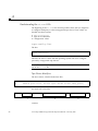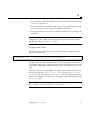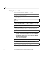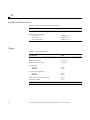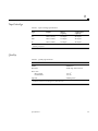
1
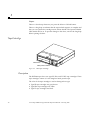
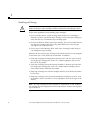
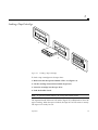
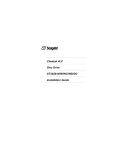
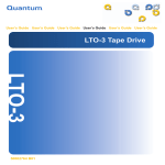
35-70 Gbyte SPARCstorage™
DLT™7000 Tape Drive Manual
Sun Microsystems Computer Company
A Sun Microsystems, Inc. Business
2550 Garcia Avenue
Mountain View, CA 94043 USA
415 960-1300
fax 415 969-9131
Part No.: 805-0648-10
Revision A, February 1997
Copyright 1997 Sun Microsystems, Inc. 2550 Garcia Avenue, Mountain View, California 94043-1100 U.S.A. All rights reserved.
This product or document is protected by copyright and distributed under licenses restricting its use, copying, distribution, and decompilation.
No part of this product or document may be reproduced in any form by any means without prior written authorization of Sun and its licensors,
if any.
Portions of this product may be derived from the UNIX® system, licensed from Novell, Inc., and from the Berkeley 4.3 BSD system, licensed from
the University of California. UNIX is a registered trademark in the United States and in other countries and is exclusively licensed by X/Open
Company Ltd. Third-party software, including font technology in this product, is protected by copyright and licensed from Sun’s suppliers.
RESTRICTED RIGHTS: Use, duplication, or disclosure by the U.S. Government is subject to restrictions of FAR 52.22714(g)(2)(6/87) and FAR 52.227-19(6/87), or DFAR 252.227-7015(b)(6/95) and DFAR 227.7202-3(a).
Sun, Sun Microsystems, the Sun logo, SunOS, AnswerBook, SunVTS, SunDiag, and Solaris are trademarks or registered trademarks of Sun
Microsystems, Inc. in the United States and in other countries. All SPARC trademarks are used under license and are trademarks or registered
trademarks of SPARC International, Inc. in the United States and in other countries. Products bearing SPARC trademarks are based upon an
architecture developed by Sun Microsystems, Inc. DLT is claimed as a trademark by Quantum Corporation in the United States and other
countries.
The OPEN LOOK® and Sun™ Graphical User Interfaces were developed by Sun Microsystems, Inc. for its users and licensees. Sun
acknowledges the pioneering efforts of Xerox Corporation in researching and developing the concept of visual or graphical user interfaces for the
computer industry. Sun holds a nonexclusive license from Xerox to the Xerox Graphical User Interface, which license also covers Sun’s licensees
who implement OPEN LOOK GUIs and otherwise comply with Sun’s written license agreements.
THIS PUBLICATION IS PROVIDED “AS IS” WITHOUT WARRANTY OF ANY KIND, EITHER EXPRESS OR IMPLIED, INCLUDING,
BUT NOT LIMITED TO, THE IMPLIED WARRANTIES OF MERCHANTABILITY, FITNESS FOR A PARTICULAR PURPOSE, OR
NON-INFRINGEMENT.
Copyright 1997 Sun Microsystems, Inc., 2550 Garcia Avenue, Mountain View, Californie 94043-1100 U.S.A. Tous droits réservés.
Ce produit ou document est protégé par un copyright et distribué avec des licences qui en restreignent l’utilisation, la copie et la décompilation.
Aucune partie de ce produit ou de sa documentation associée ne peut être reproduite sous aucune forme, par quelque moyen que ce soit, sans
l’autorisation préalable et écrite de Sun et de ses bailleurs de licence, s’il y en a.
Des parties de ce produit pourront être derivées du système UNIX® licencié par Novell, Inc. et du système Berkeley 4.3 BSD licencié par
l’Université de Californie. UNIX est une marque enregistrée aux Etats-Unis et dans d’autres pays, et licenciée exclusivement par X/Open
Company Ltd. Le logiciel détenu par des tiers, et qui comprend la technologie relative aux polices de caractères, est protégé par un copyright et
licencié par des fournisseurs de Sun.
Sun, Sun Microsystems, le logo Sun, SunOS, AnswerBook, SunVTS, SunDiag, et Solaris sont des marques déposées ou enregistrées de Sun
Microsystems, Inc. aux Etats-Unis et dans d’autres pays. Toutes les marques SPARC, utilisées sous licence, sont des marques déposées ou
enregistrées de SPARC International, Inc. aux Etats-Unis et dans d’autres pays. Les produits portant les marques SPARC sont basés sur une
architecture développée par Sun Microsystems, Inc. La marque DLT a été déposée par Quantum Corporation aux Etats-Unis et dans d'autres
pays.
Les utilisateurs d’interfaces graphiques OPEN LOOK® et Sun™ ont été développés de Sun Microsystems, Inc. pour ses utilisateurs et licenciés.
Sun reconnaît les efforts de pionniers de Xerox Corporation pour la recherche et le développement du concept des interfaces d’utilisation visuelle
ou graphique pour l’industrie de l’informatique. Sun détient une licence non exclusive de Xerox sur l’interface d’utilisation graphique, cette
licence couvrant aussi les licenciés de Sun qui mettent en place les utilisateurs d’interfaces graphiques OPEN LOOK et qui en outre se conforment
aux licences écrites de Sun.
CETTE PUBLICATION EST FOURNIE "EN L’ETAT" SANS GARANTIE D’AUCUNE SORTE, NI EXPRESSE NI IMPLICITE, Y COMPRIS,
ET SANS QUE CETTE LISTE NE SOIT LIMITATIVE, DES GARANTIES CONCERNANT LA VALEUR MARCHANDE, L’APTITUDE DES
PRODUITS A REPONDRE A UNE UTILISATION PARTICULIERE OU LE FAIT QU’ILS NE SOIENT PAS CONTREFAISANTS DE PRODUITS
DE TIERS.
Please
Recycle
Contents
Preface. . . . . . . . . . . . . . . . . . . . . . . . . . . . . . . . . . . . . . . . . . . . . . . . . . . .
v
1. Installation . . . . . . . . . . . . . . . . . . . . . . . . . . . . . . . . . . . . . . . . . . .
1
Installing the Tape Drive . . . . . . . . . . . . . . . . . . . . . . . . . . . . . . . .
1
Troubleshooting . . . . . . . . . . . . . . . . . . . . . . . . . . . . . . . . . . . . . . .
6
Operation. . . . . . . . . . . . . . . . . . . . . . . . . . . . . . . . . . . . . . . . . . . .
7
Front Panel Controls and Indicators . . . . . . . . . . . . . . . . . . . . . .
7
Tape Cartridge . . . . . . . . . . . . . . . . . . . . . . . . . . . . . . . . . . . . . . . .
10
Description . . . . . . . . . . . . . . . . . . . . . . . . . . . . . . . . . . . . . . . .
10
Write-Protect. . . . . . . . . . . . . . . . . . . . . . . . . . . . . . . . . . . . . . .
11
Handling and Storage . . . . . . . . . . . . . . . . . . . . . . . . . . . . . . .
12
Loading a Tape Cartridge . . . . . . . . . . . . . . . . . . . . . . . . . . . . . . .
13
Selecting Density . . . . . . . . . . . . . . . . . . . . . . . . . . . . . . . . . . . . . .
14
Valid Densities . . . . . . . . . . . . . . . . . . . . . . . . . . . . . . . . . . . . .
14
Selecting Density Using the Front Panel. . . . . . . . . . . . . . . .
14
Selecting Density Using Software Commands. . . . . . . . . . .
15
2.
iii
iv
Unloading a Tape Cartridge . . . . . . . . . . . . . . . . . . . . . . . . . . . . .
16
Using a Cleaning Tape Cartridge . . . . . . . . . . . . . . . . . . . . . . . . .
17
System Diagnostic Support. . . . . . . . . . . . . . . . . . . . . . . . . . . . . .
17
A. Modifying the st.conf File . . . . . . . . . . . . . . . . . . . . . . . . . . . .
19
Understanding the st.conf File . . . . . . . . . . . . . . . . . . . . .
20
Modifying the st.conf File . . . . . . . . . . . . . . . . . . . . . . . . .
22
B. Specifications . . . . . . . . . . . . . . . . . . . . . . . . . . . . . . . . . . . . . . . . .
25
Physical . . . . . . . . . . . . . . . . . . . . . . . . . . . . . . . . . . . . . . . . . . . . . .
25
Electrical . . . . . . . . . . . . . . . . . . . . . . . . . . . . . . . . . . . . . . . . . . . . .
25
Interface and Performance . . . . . . . . . . . . . . . . . . . . . . . . . . . . . .
26
Timing . . . . . . . . . . . . . . . . . . . . . . . . . . . . . . . . . . . . . . . . . . . . . . .
26
Tape Cartridge . . . . . . . . . . . . . . . . . . . . . . . . . . . . . . . . . . . . . . . .
27
Quality. . . . . . . . . . . . . . . . . . . . . . . . . . . . . . . . . . . . . . . . . . . . . . .
27
35-70 Gbyte SPARCstorage DLT7000 Tape Drive Manual—February 1997
Preface
The 35-70 Gbyte SPARCstorage™ DLT™7000 Tape Drive Manual provides
installation instructions and user information for the DLT7000 Tape Drive.
These instructions are designed for a system administrator.
How This Book Is Organized
Chapter 1, “Installation,” provides instructions on how to install the tape
drive into systems or enclosures. The steps in this chapter should be performed
in conjunction with installation instructions specific to the system or enclosure
into which the tape drive will be installed. This chapter also includes
troubleshooting information.
Chapter 2, “Operation,” provides information about using the tape drive.
Appendix A, “Modifying the st.conf File,” provides instructions on how to
modify the st.conf file for tape drives that are being connected to
workstations using the SunOS™ 5.5 and 5.5.1 operating systems.
Appendix B, “Specifications,” provides specifications for the tape drive and
tape cartridge.
v
Software Commands
Brief descriptions of some software commands commonly used with tape
drives are in the following table. Refer to the Solaris 2.x Handbook for SMCC
Peripherals, man pages or the AnswerBook™ online documentation for more
information.
Table 1
Command
Description
ufsdump
Creates incremental or full backups
ufsrestore
Retrieves data backed up using ufsdump
tar
Creates tape archives and adds or extracts files
mt
Sends commands to magnetic tape devices
st
Acts as a device driver and interface to SCSI tape devices
tapetool
OpenWindows™ tool that reads files from tape or archives files to
tape
cpio
Copies file archives in and out
For information on:
•
•
•
•
Shutting down the system
Booting the system
Configuring devices
Other basic software procedures
See one or more of the following:
vi
•
Solaris 2.x Handbook for SMCC Peripherals for Solaris™ 2.x software
commands.
•
AnswerBook online documentation for the complete set of documentation
supporting the Solaris 2.x software environment.
•
Other software documentation that you received with your system.
35-70 Gbyte SPARCstorage DLT7000 Tape Drive Manual—February 1997
Shell Prompts
The following table shows the default system prompt and superuser prompt
for the C shell, Bourne shell, and Korn shell.
Shell
Prompt
C shell
machine_name%
C shell superuser
machine_name#
Bourne shell and Korn shell
$
Bourne shell and Korn shell superuser
#
Typographic Conventions
The following table describes the typographic changes used in this book.
Typeface or
Symbol
Meaning
Example
AaBbCc123
The names of commands,
files, and directories;
on-screen computer output
Edit your .login file.
Use ls -a to list all files.
machine_name% You have mail.
AaBbCc123
What you type, contrasted
with on-screen computer
output
AaBbCc123
Command-line placeholder:
replace with a real name or
value
To delete a file, type rm filename.
AaBbCc123
Book titles, new words or
terms, or words to be
emphasized
Read Chapter 6 in the User’s Guide.
These are called class options.
You must be root to do this.
Preface
machine_name% su
Password:
vii
Ordering Sun Documents
SunDocsSM is a distribution program for Sun Microsystems technical
documentation. Easy, convenient ordering and quick delivery is available from
SunExpress™. You can find a full listing of available documentation on the
World Wide Web: http://www.sun.com/sunexpress/
Country
Telephone
Fax
United States
1-800-873-7869
1-800-944-0661
United Kingdom
0-800-89-88-88
0-800-89-88-87
France
0800-90-61-57
0800-90-61-58
Belgium
02-720-09-09
02-725-88-50
Luxembourg
32-2-720-09-09
32-2-725-88-50
Germany
01-30-81-61-91
01-30-81-61-92
The Netherlands
06-022-34-45
06-022-34-46
Sweden
020-79-57-26
020-79-57-27
Switzerland
0800-55-19-26
0800-55-19-27
Japan
0120-33-9096
0120-33-9097
Sun Welcomes Your Comments
Please use the Reader Comment Card that accompanies this document. We are
interested in improving our documentation and welcome your comments and
suggestions.
If a card is not available, you can email or fax your comments to us. Please
include the part number of your document in the subject line of your email or
fax message.
•
•
viii
Email:
[email protected]
Fax:
SMCC Document Feedback
1-415-786-6443
35-70 Gbyte SPARCstorage DLT7000 Tape Drive Manual—February 1997
Installation
1
This chapter describes how to install, configure, and troubleshoot the DLT7000
tape drive.
Installing the Tape Drive
1. Determine your operating system using the uname -rs command.
!
Caution – For SunOS 5.5 or 5.5.1 operating systems, you must perform the
procedures in Appendix A, “Modifying the st.conf File," before proceeding.
2. Shut down the operating system.
Use either the init or shutdown command. See the man pages for these
commands or the Solaris AnswerBook online documentation.
3. Find an available SCSI device identifier (SCSI ID) for the tape drive.
To check for an available SCSI ID, enter probe-scsi-all at the ok
prompt. Use a SCSI ID that is not returned by this command. Tape drives
are usually set to a SCSI ID of 4 or 5. Write down the SCSI ID (and SCSI host
adapter identifier) for future use.
Note – Do not choose SCSI ID 7; it is reserved for the host adapter.
4. Turn off the power to your system and then to your peripherals.
1
1
5. Prepare your system or enclosure for servicing.
Follow the procedures in the service manual for your system or enclosure.
6. Install the tape drive.
Refer to the procedures in your system or enclosure service manual. Install
this drive as you would any full-height device.
a. Connect the SCSI and power cables to the connectors on the back of
the tape drive (Figure 1-1).
SCSI
connector
Figure 1-1
2
Power
connector
DLT7000 Tape Drive Cable Connectors
35-70 Gbyte SPARCstorage DLT7000 Tape Drive Manual—February 1997
1
b. Set the SCSI ID.
For systems or enclosures with a SCSI ID cable, install the SCSI ID cable
as shown in Figure 1-2 and set the SCSI ID for the tape drive using the
SCSI ID switch on the system or enclosure.
SCSI ID
connectors
Figure 1-2
SCSI ID Connectors
For systems or enclosures that do not have a SCSI ID cable, connect the
jumpers as shown in Figure 1-3.
SCSI ID 0
SCSI ID 1
SCSI ID 2
SCSI ID 3
SCSI ID 4
SCSI ID 5
SCSI ID 6
SCSI ID 7
SCSI ID 8
SCSI ID 9
SCSI ID 10
SCSI ID 11
SCSI ID 12
SCSI ID 13
SCSI ID 14
SCSI ID 15
Figure 1-3
Setting SCSI ID Jumpers
Note – Although there are other switches and connectors on the tape drive,
they are inactive in Sun™ configurations.
Installation
3
1
7. Power on your peripherals and then your system.
Note – If your system starts to reboot, interrupt the reboot process by
pressing the Stop and A keys together.
8. Reboot your system using the boot -r command.
9. Load a tape cartridge into the tape drive (see “Loading a Tape Cartridge”
on page 13).
Wait for the tape drive to fully load the tape cartridge.
Note – If all of the LEDs on the right or left side of the tape drive front panel
are blinking, then the tape drive has failed its power-on self-test (POST). Go to
“Troubleshooting” on page 6.
10. Determine which remote number the tape drive has been mapped to.
a. Process the remote numbers in the /dev/rmt directory.
# ls -l /dev/rmt/? | sed 's/.*rmt\///'
For example, a system with two tape drives (one connected to an internal
SCSI host adapter and one to an external host adapter) might return:
# ls -l /dev/rmt/? | sed 's/.*rmt\///'
0 -> ../../devices/iommu@f,e0000000/sbus@f,e0001000/dma@f,81000/esp@f,80000/st@4,0:
1 -> ../../devices/iommu@f,e0000000/sbus@f,e0001000/QLGC,isp@2,10000/st@5,0:
Remote number
SCSI host adapter
SCSI ID
b. Find the remote number that contains the controller and SCSI ID (st)
number for the tape drive you installed.
In the previous example, the remote number 0 would be used for a tape
drive connected to SCSI ID 4 on SCSI host adapter at
dma@f,81000/esp@f,80000.
4
35-70 Gbyte SPARCstorage DLT7000 Tape Drive Manual—February 1997
1
11. Verify that the system recognizes the tape drive.
#mt -f /dev/rmt/remote_number status
•
A correct response would resemble:
#mt -f /dev/rmt/3 status
Other tape drive:
sense key(0x0)= No Additional Sense
file no= 0
block no= 0
#
residual= 0
retries= 0
Other tape drive on the first line of the output indicates that the tape
drive is correctly recognized. The rest of the output does not matter.
•
Incorrect responses include:
• No tape loaded or drive offline indicates there is no cartridge
in the drive or that the cartridge is not yet loaded. Install a cartridge or
wait for the cartridge load to complete and retry the mt status
command.
• No such file or directory indicates there is no tape drive
attached to that rmt (remote) number. Try another remote number.
• SCSI tape drive indicates the st.conf entry is incorrect. You must
edit the st.conf file and reboot until you no longer see SCSI tape
drive.
The Tape In Use LED should be lit, signifying that the drive is ready for use.
Go to Chapter 2, “Operation".
Note – If the tape drive does not complete POST, or if the right or left side
LEDs blink repeatedly, go to “Troubleshooting” on page 6.
Installation
5
1
Troubleshooting
If the DLT7000 tape drive fails during POST or operation, use Table 1-1 to
determine the problem and the action to take.
Table 1-1
6
Troubleshooting
Symptom:
Your system does not recognize the DLT7000 tape drive.
Action:
Make sure that:
• The SCSI ID is unique.
• The SCSI data cable is not loose.
• The SCSI bus is correctly terminated.
• You have rebooted the system using the boot -r command.
Symptom:
All LEDs on the right- or left-side of the tape drive front panel
blink.
Action:
Try to unload the tape and reinitialize the drive by pressing the
Unload button, or turn the drive power off and then on again.
The right or left side LEDs stop blinking and the drive tries to
reinitialize. The LEDs should turn on steady again and go off if
the test succeeds.
If all right or left side LEDs still blink, the drive has a hardware
failure.
35-70 Gbyte SPARCstorage DLT7000 Tape Drive Manual—February 1997
2
Operation
This chapter gives details of the basic operation of the DLT7000 tape drive, and
the meanings of the front panel displays.
For information about software commands, refer to the Solaris Handbook for
SMCC Peripherals or the AnswerBook documentation for your operating
system.
Front Panel Controls and Indicators
W
2.6
rite
Pr
ote
c
ted
6.0
10
.0/
15
.0
20
Ta
p
In e
Us
e
.0
Us
35
.0
Co
mp
re
ss
De
ns
Ov ity
er
rid
e
Op
er
Ha ate
nd
le
Un
Se
lec
t
Figure 2-1
e
Cl
ea
n
Ta ing
pe
loa
d
DLT7000 Front Panel
7
2
Left Front Panel LEDs
The tape drive has seven left front panel LEDs (Figure 2-1). The LEDs are
described in Table 2-1.
Table 2-1
Left Front Panel LEDs
LED
State
Operating Condition
2.6
On/Blinking
1
Tape is recorded in 2.6 Gbyte format
6.0
On/Blinking 1
Tape is recorded in 6.0 Gbyte format
10.0/15.0
20.0
On/Blinking
On/Blinking
1
1
1
Tape is recorded in 10.0 or 15.0 Gbyte format
Tape is recorded in 20.0 Gbyte format
Tape is recorded in 35.0 Gbyte format
35.0
On/Blinking
Compress2
On
Compression mode is enabled.
Off
Compression mode is disabled.
On
You selected a density from the front panel.
Off
Density will be selected by the host.
Blinking
The tape drive is in density selection mode.
On
POST is starting.
Blinking
A POST error occurred.
Density Override
All LEDs
1. A blinking LED signifies that you have used the Select button to choose a density other than the tape
cartridge’s default or pre-recorded density.
2. Compression can only be done in 10, 15, 20, and 35 Gbyte densities.
Select Button
The Select button is used to select the record density of the tape cartridge. See
“Selecting Density" for more information.
Cartridge Insert/Release Handle
Operate the cartridge insert/release handle to load a cartridge or to eject a
cartridge only when the Operate Handle LED is on, and after the beeper
sounds. The handle lifts to the open position and lowers to the closed position.
8
35-70 Gbyte SPARCstorage DLT7000 Tape Drive Manual—February 1997
2
Right Front Panel LEDs
The tape drive has four right front panel LEDs (Figure 2-1). The LEDs are
described in Table 2-2.
Table 2-2
Right Front Panel LEDs
LED
State
Operating Condition
Write Protected
On
Tape is write-protected.
Off
Tape is write-enabled.
On
Tape is loaded and ready for use.
Blinking
Tape is in use.
On
Drive head needs cleaning, or the tape is
bad (See “Using a Cleaning Tape
Cartridge” on page 17).
Off
Cleaning is complete, or cleaning is
unnecessary.
On
Okay to operate the cartridge
insert/release handle.
Off
Do not operate the cartridge insert/release
handle.
On
POST is starting.
Blinking
An error has occurred. See Table 1-1.
Tape In Use
Use Cleaning Tape
Operate Handle
All LEDs
Unload Button
The Unload button is used primarily to unload the tape. When you push the
Unload button, the DLT7000 drive waits until an active write to tape is
completed before beginning the unload sequence. See “Unloading a Tape
Cartridge” on page 16.
If the drive is in an error state, pushing the Unload button causes the drive to
reset and unload the tape if possible. See “Troubleshooting” on page 6.
Operation
9
2
Beeper
There is a short beep whenever you press the Select or Unload button.
There is a long beep to indicate that the tape unload sequence is complete and
that you can operate the cartridge insert/release handle. The Operate Handle
LED should also be on. To prevent damage to the drive, wait for the long beep
before opening the door.
Tape Cartridge
Label area
Write-protect switch
Figure 2-2
DLT Tape Cartridge
Description
The DLT7000 tape drive uses type III, IIIxt, and IV DLT tape cartridges. These
tape cartridges contain 1/2 inch magnetic metal particle tape.
The color of the tape cartridge is used to distinguish its type:
•
•
•
10
Type III tape cartridges are gray/brown.
Type IIIxt tape cartridges are white.
Type IV tape cartridges are black.
35-70 Gbyte SPARCstorage DLT7000 Tape Drive Manual—February 1997
2
For more information about tape cartridges, see Table 2-3.
Table 2-3
Tape Cartridge Specifications
Type
Length
Native
Capacity
Compressed
Capacity1
III
356m (1167 ft)
10 Gbytes
20 Gbytes
IIIxt
541m (1778 ft)
15 Gbytes
30 Gbytes
IV
541m (1778 ft)
35 Gbytes
70 Gbytes
1. Assumes a typical compression ratio of 2:1. The compression ratio will vary depending upon the type of
data being compressed.
Write-Protect
The tape cartridge has a write-protect switch (Figure 2-2) to prevent accidental
erasure of data. This switch can be set prior to or after inserting the tape
cartridge into the tape drive.
•
To write protect a tape cartridge, move the switch to the left so that a small
rectangle is visible.
•
To write enable a tape cartridge, move the switch to the right so that the
rectangle is not visible.
If the write-protect switch is changed while the tape cartridge is being written
to by the tape drive, the change does not take effect until the current write
operation completes.
Operation
11
2
Handling and Storage
!
Caution – Do not drop or bang the tape cartridge. This can displace the tape
leader, making the tape cartridge unusable and possibly damaging the drive.
Follow these guidelines when handling tape cartridges:
•
Do not forcibly remove a tape cartridge from the drive. If a cartridge is
difficult to remove, reinsert the tape cartridge, wait for the tape cartridge to
load, and then try to unload the tape cartridge again.
•
Do not use adhesive labels on the tape cartridge. Use only the labels that fit
into the tape cartridge label area. Using other labels may cause the tape
cartridge to jam in the tape drive.
•
Do not move a DLT7000 tape drive with a tape cartridge loaded; doing so
can damage the tape cartridge.
When not in use, return a tape cartridge to the plastic enclosure it was shipped
in and store it in a clean, dust-free environment. In addition:
•
Store tape cartridges in temperatures between 20˚C and 30˚C (68˚F to 86˚F).
For longer tape cartridge life, store it at a stable temperature and as close
22˚C (72˚F) as possible.
•
Store tape cartridges where the relative humidity is between 30% and 50%.
For longer tape cartridge life, store it at a stable relative humidity and as
close to 40% relative humidity as possible.
•
Keep tape cartridges out of direct sunlight and away from heaters and other
heat sources.
•
Keep tape cartridges away from electromagnetic interference sources, such
as terminals, motors, and video or X-ray equipment. Data on the tape can be
altered.
Note – If a tape cartridge has been exposed to extreme heat or cold, stabilize
the cartridge at room temperature for the same amount of time it was exposed
(up to 24 hours).
12
35-70 Gbyte SPARCstorage DLT7000 Tape Drive Manual—February 1997
2
Loading a Tape Cartridge
2
3
4
Figure 2-3
Loading a Tape Cartridge
To load a tape cartridge into the tape drive:
1. Make sure that the Operate Handle LED is on (Figure 2-1).
2. Lift the cartridge insert/release handle (Figure 2-3).
3. Insert the cartridge into the tape drive.
4. Push the handle closed.
Note – To prevent handle failures, do not flip the handle closed.
The Operate Handle LED turns off and the Tape In Use LED blinks to show the
tape is loading. When the tape is loaded, the Tape In Use LED turns on steady.
The tape is now ready for use.
Operation
13
2
Selecting Density
You can select the density that the tape cartridge will record data by using the
front-panel Select button or by using a software command. In either case, the
new density does not take effect until a write from beginning of tape (BOT) is
executed. Until then, the original density will be used.
Note – Blank tape cartridges do not have default densities. The DLT7000 will
not light any LEDs on the left-side of the front panel until data has been
written to the tape.
Valid Densities
Table 2-4 shows the densities that can be selected for the DLT7000 tape drive.
Table 2-4
Selectable Densities
Tape Type
Selectable Densities
III
2.6 Gbyte, 6.0 Gbyte, 10.0 Gbyte native or 10.0 Gbyte compressed
IIIxt
15.0 Gbyte native or 15.0 Gbyte compressed
IV
20.0 Gbyte, 35.0 Gbyte native or 20.0 Gbyte, 35.0 Gbyte compressed
Selecting Density Using the Front Panel
To select density using the front panel:
1. Load the tape cartridge into the tape drive.
The Tape in Use LED blinks while the tape loads. After the tape is loaded,
the Tape in Use LED remains lit. The LEDs on the left side of the drive light
to show the tape cartridge’s prerecorded density.
2. Press the Select button until the LED(s) showing the desired density light.
The original density LED(s) will go out. The selected density LED(s) will be
on steady and the Density Override LED will blink. Then the selected
density will blink and the LED(s) for the original density and the Density
Override LED will be steady.
3. When a write from BOT occurs, the selected density will be used.
The selected density and the Density Override LEDs are on steady.
14
35-70 Gbyte SPARCstorage DLT7000 Tape Drive Manual—February 1997
2
Selecting Density Using Software Commands.
To select the recording density by using software commands:
1. Choose a density specifier from Table 2-5.
Table 2-5
Density
Specifiers
Density Specifiers
Cartridge Types and Capacities
Type IV
Type IIIxt
Type III
l
20 Gbytes
15 Gbytes
10 Gbytes
m
40 Gbytes1
30 Gbytes1
20 Gbytes1
h
35 Gbytes
15 Gbytes
10 Gbytes
u
70 Gbytes
1
30
Gbytes1
20 Gbytes1
1Assumes a typical compression ratio of 2:1. The compression ratio will vary depending upon the type of
data being compressed.
2. Type the mt command with the appropriate density specifier.
For example:
#mt -f /dev/rmt/3u rewind
See the st and mt man pages for more information.
Operation
15
2
Unloading a Tape Cartridge
Figure 2-4
!
1
2
3
4
Unloading a Tape Cartridge
Caution – Remove a tape cartridge from the drive before turning off the host
system power. Failure to remove a tape cartridge can result in cartridge and
drive damage.
To unload a tape cartridge from the tape drive:
1. Press the Unload button (Figure 2-4).
The Tape in Use LED blinks as the tape rewinds. This may take between 17
seconds and two minutes.
2. When the Operate Handle LED turns on and the beeper sounds, pull the
cartridge insert/release handle open to eject the cartridge.
3. Remove the cartridge.
4. Push the handle closed.
16
35-70 Gbyte SPARCstorage DLT7000 Tape Drive Manual—February 1997
2
Using a Cleaning Tape Cartridge
!
Caution – Use only a DLT Type III cleaning cartridge to clean the
tape drive.
When the Use Cleaning Tape LED lights:
1. Load cleaning tape cartridge into the tape drive. See “Loading a Tape
Cartridge".
Note – If the Use Cleaning Tape LED lights after you load the cleaning tape
cartridge, cleaning has not been done because the cleaning tape cartridge is
expired. Replace the cleaning tape cartridge. A cleaning tape usually lasts
about 20 cleanings.
2. Wait for the cleaning process to complete.
The Tape In Use LED stops blinking. The beeper sounds and the Operate
Handle LED lights.
3. Unload the cleaning tape cartridge. See “Unloading a Tape Cartridge".
4. Record the date of the cleaning on the cartridge label.
Note – If a data cartridge causes the Use Cleaning Tape LED to blink or the
Use Cleaning Tape LED still lights after you clean the drive head, then the data
cartridge may be damaged. Try another data tape cartridge. If the second tape
cartridge works, then backup your original tape cartridge onto another tape
cartridge. Discard the old tape cartridge.
System Diagnostic Support
SunVTS™ 1.0 diagnostic software, which was distributed with the Solaris 2.5
software environment, requires that you apply patch number 103097-01 to your
system. SunVTS 2.0 diagnostic software and later versions do not require a
patch. You can obtain any needed patches through your normal service
channels.
This tape drive is not supported by the SunDiag™ diagnostic software.
Operation
17
2
18
35-70 Gbyte SPARCstorage DLT7000 Tape Drive Manual—February 1997
Modifying the st.conf File
A
The Solaris software environment recognizes all tape drives and autoloaders
that were supported by Sun when your operating system was released. If your
system uses SunOS releases 5.5 or 5.5.1, which were released before the
DLT7000 tape drive, you need to modify the /kernel/drv/st.conf file so
that your Solaris software will recognize the DLT7000 tape drive.
If you are familiar with this procedure, go to “Modifying the st.conf File” on
page 22. For more information on this procedure, go to “Understanding the
st.conf File” on page 20.
19
A
Understanding the st.conf File
The beginning of the st.conf file contains possible values that you might use
to configure third-party or other unsupported tape drives. These values are
divided into three sections:
•
•
•
tape-config-list
Tape device identifiers
Configuration values
tape-config-list
The line:
#tape-config-list=
indicates the start of values that the operating system will use to configure
previously unsupported tape devices.
Note – There can only be one active (uncommented) tape-config-list=
line in the st.conf file.
Tape Device Identifiers
The next section, which includes lines like:
#
#
"ARCHIVE Python 28454","Archive Python 4mm Helical Scan","ARCH_Python",
"ARCHIVE Python 29279", "Archive Python 4mm DAT Stacker","ARCH_Python",
and ends with a line like:
#
"\076\000",
1
"Fujitsu 1/2\" Cartridge",
"Fujitsu_half";
2
contains:
20
35-70 Gbyte SPARCstorage DLT7000 Tape Drive Manual—February 1997
3
A
1. The information about the tape device that the operating system sees when
it 'looks at' a tape device.
2. The information the operating system outputs when queried about the tape
device (by programs such as SunVTS diagnostic software).
3. A string which acts as a pointer to values that will be used to configure the
tape device.
Note – The first two lines of the example end in commas. The last line in the
example ends with a semi-colon. You must follow this format when adding
multiple tape devices to the st.conf file.
Configuration Values
The third section contains the values that will be used to configure the tape
devices. It has lines like:
#ARCH_Python
=
1,0x2c,0,0xde39,4,0x00,0x8c,0x8c,0x8c,3;
The part of the line before the equal sign (=) is the string that is linked to the
values that will be used to configure a tape device. The second part of the line
contains the configuration values. These values are well defined in the st man
page.
If you look at the first two examples in the Tape Device Identifiers section, you
will see that both the ARCHIVE Python 28454 and the ARCHIVE Python
29279 lines end with the string ARCH_Python. This means that the operating
system will configure both tape devices according to the parameters set in the
ARCH_Python line.
Note – Each line in the configuration section must start with a unique string.
Also, each line in this section ends in a semi-colon(;).
Modifying the st.conf File
21
A
Modifying the st.conf File
Read this entire procedure before editing the st.conf file.
Note – The syntax is critical. Verify the placement of commas, semicolons, and
beginning and ending quotation marks.
1. Become superuser.
% su
Password:
#
2. Make a copy of the original st.conf file as a backup (st.conf.old).
#cp /kernel/drv/st.conf /kernel/drv/st.conf.old
3. Edit the st.conf file.
Using an editor, scroll through the st.conf file to the following line:
#tape-config-list=
a. Delete the # character that begins the line, if it hasn't already been
removed.
b. Using the editor, continue to scroll until you come to the end of the
“Tape Device Identifiers” section.
The line will look something like:
#
"\076\000","Fujitsu 1/2\" Cartridge", "Fujitsu_half";
c. On the next line, add the following entry exactly as shown:
“SUN
DLT7000”, “Quantum DLT 7000”, “QDLT7”;
5 spaces
22
35-70 Gbyte SPARCstorage DLT7000 Tape Drive Manual—February 1997
A
Note – If multiple devices are enabled (lines uncommented) only the last
uncommented line with this format must end with a semicolon. All previous
lines with this format must end with a comma.
d. Using the editor, continue to scroll until you come to the end of the
“Configuration Values” section.
The line will look something like:
#WtQIC =
1,0x32,512,0x0624,1,0x00,0;
e. On the next line, add the following entry exactly as shown:
QDLT7 = 1,0x36,0,0x1D639,4,0x82,0x83,0x84,0x85,2;
Note – All lines in this section end with semicolons.
f. Save and exit the file.
4. Go to Step 2 on page 1 and continue the installation procedure.
Modifying the st.conf File
23
A
24
35-70 Gbyte SPARCstorage DLT7000 Tape Drive Manual—February 1997
B
Specifications
This chapter contains the specifications for the DLT7000 tape drive.
Physical
Table B-1 Physical Specifications
Form Factor
Width
Depth
Height
Weight
5.25 inches
133.35 mm
5.84 inches
148.3 mm
9.6 inches
243.8 mm
3.4 inches
86.3 mm
6.7 pounds
2.9 kg
Electrical
Table B-2 Electrical Specifications
Specification
5V (±5%)
12V (±10%)
Steady state
3.6A
1.6A
Maximum1
3.8A
2.6A
1. Maximum values are for about 300 ms duration.
25
B
Interface and Performance
Table B-3 Interface and Performance Specifications
Specification
Value
Buffer size
4 Mbytes
Transfer Rates (maximum)
User native:
Raw native:
User compressed:
5.2 Mbytes/sec
3 Mbytes/sec
10 Mbytes/sec
Timing
Table B-4 Timing Specifications
Specification
Value
Read/Write tape speed
160 in/sec
Rewind tape speed
175 in/sec
Linear search tape speed
175 in/sec
Rewind times
Average
Maximum
1 min
2 min
Access times (from BOT)
Average
Maximum
1 min
2 min
Load to BOT (previously written)
48 sec1
Unload from BOT
17 sec
1. The time is slightly longer if you are using a blank tape.
26
35-70 Gbyte SPARCstorage DLT7000 Tape Drive Manual—February 1997
B
Tape Cartridge
Table B-5 Tape Cartridge Specifications
Type
Length
Native
Capacity
Compressed
Capacity1
III
356m (1167 ft)
10 Gbytes
20 Gbytes
IIIxt
541m (1778 ft)
15 Gbytes
30 Gbytes
IV
541m (1778 ft)
35 Gbytes
70 Gbytes
1. Assumes a typical compression ratio of 2:1. The compression ratio will vary depending upon the type of
data being compressed.
Quality
Table B-6 Quality Specifications
Specification
Value
MTBF
200,000 hrs1
Head life
30,000 tape motion hours
Error rates
Recoverable
Undetectable
1 in 1017
1 in 1027
Tape life
500,000 passes
1. Sun Microsystems, Inc. does not warrant that the predicted MTBF is representative of any particular unit
installed for customer use. Actual figures vary from unit to unit.
Specifications
27
B
28
35-70 Gbyte SPARCstorage DLT7000 Tape Drive Manual—February 1997
Index
Numerics
D
2.6, 5.0, 10.0/15.0, 20.0, 35.0 LEDs, 8
density
selecting, 14
front panel, 14
software commands, 15
valid, 14
Density Override LED, 8
determining operating system, 1
determining SCSI ID, 1
diagnostic software, 17
B
back of tape drive, 2
beeper, 10
beginning of tape (BOT), 14, 26
boot -r command, 4
button
Select, 8
Unload, 9
C
cartridge insert/release handle, 8
cartridge, See tape cartridge
cleaning tape cartridge, 17
command
boot -r, 4
uname -rs, 1
Compress LED, 8
configuration files, modifying, 19
connectors, 2, 3
E
ejecting a tape cartridge, 16
electrical specifications, 25
H
handle, cartridge insert/release, 8
I
installation, 1
interface and performance
specifications, 26
29
L
T
LEDs
blinking
all, 6, 8
density, 8
Density Override, 8
Tape In Use, 9
left front panel, 8
right front panel, 9
left front panel LEDs, 8
loading a tape cartridge, 13
tape cartridge
capacity, 10
cleaning, 17
density, 14
handling and storage, 12
loading, 13
specifications, 27
types, 10
unloading, 16
write-protect switch, 11
tape drive
back, 2
connectors, 2, 3
front panel, 7
installation, 1
operation, 7
Tape In Use LED, 9
target address, See SCSI ID
timing specifications, 26
troubleshooting, 6
O
Operate Handle LED, 9
operating system, determining, 1
P
patch, SunVTS, 17
physical specifications, 25
Q
quality specifications, 27
S
SCSI device identifier, See SCSI ID
SCSI ID
cable, 3
determining, 1
jumpers, 3
Select button, 8
specifications
electrical, 25
interface and performance, 26
physical, 25
quality, 27
tape cartridge, 27
timing, 26
st.conf file, 19
SunDiag, 17
SunVTS, 17
30
U
uname -rs command, 1
Unload button, 9
unloading a tape cartridge, 16
Use Cleaning Tape LED, 9, 17
V
valid densities, 14
W
Write Protected LED, 9
35-70 Gbyte SPARCstorage DLT7000 Tape Drive Manual—February 1997
Reader Comment Card
Your comments and suggestions are important to us. Please let us know what
you think about the 35-70 Gbyte SPARCstorage DLT7000 Tape Drive Manual,
part number 805-0648-10.
Yes ❑ No ❑
1. Were the procedures well documented?
Please explain:
Yes ❑ No ❑
2. Were the tasks easy to follow?
Please explain:
Yes ❑ No ❑
3. Were the illustrations clear?
Please explain:
Yes ❑ No ❑
4. Was the information complete and easy to find?
Please explain:
5. Do you have additional comments about this manual?
You can send detailed comments via email to [email protected], or send
a fax to SMCC Doc Feedback at (415) 786-6443.
Your Name:
Title:
Company Name:
Address:
City:
Country:
State/Province:
Zip/Postal Code:
Email Address:
Telephone:
Thank you.