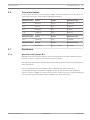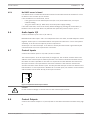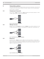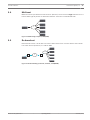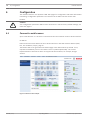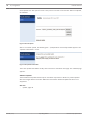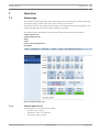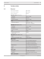
1
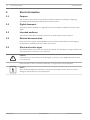
IP Audio Interface
PRS-1AIP1
en
Operating Manual
IP Audio Interface
Table of Contents | en
3
Table of contents
1
Important Safety Instructions
5
2
Short information
6
2.1
Purpose
6
2.2
Digital document
6
2.3
Intended audience
6
2.4
Related documentation
6
2.5
Alerts and notice signs
6
2.6
Conversion tables
7
2.7
Disclaimers
7
2.7.1
Bosch Security Systems B.V.
7
3
System overview
8
3.1
Application
8
3.2
Key product features
8
3.3
Package content
8
3.4
Product view
9
3.4.1
Front view
3.4.2
Rear view
10
4
Installation
12
4.1
Mechanical installation
12
4.2
Network (step 1)
12
4.3
Audio Outputs (step 2)
12
4.4
Power supply (step 3)
12
4.5
IP address (step 4)
12
4.5.1
No DHCP server is found
13
4.6
Audio Inputs 1/2
13
4.7
Control Inputs
13
4.8
Control Outputs
13
5
Connection options
14
5.1
Unicast (point to point)
14
5.2
Multiple Unicast
14
5.3
Broadcast
14
5.4
Multicast
15
5.5
Re-broadcast
15
6
Configuration
16
6.1
Connect to web browser
16
6.2
Configuration page
17
6.2.1
Network
18
6.2.2
Streaming
19
6.2.3
Partner Table
20
6.2.4
Outgoing Route Table
22
6.2.5
Control
23
6.2.6
Audio Settings
24
6.2.7
Supervision
27
6.2.8
Control Input Mapping Table
29
9
6.2.9
Control Output Mapping Table
30
6.2.10
Serial (RS-232/RS-485)
31
6.2.11
SNMP
32
Bosch Security Systems B.V.
Operating Manual
2013.03 | V2.0 |
4
en | Table of Contents
IP Audio Interface
6.2.12
Security
33
6.2.13
Default settings
34
6.2.14
Configuration view
35
6.2.15
Update
36
7
Operation
39
7.1
Status page
39
7.1.1
Control Inputs (1..8)
39
7.1.2
Control Outputs (1..8)
40
7.1.3
Audio
40
7.1.4
Codec
40
7.1.5
Power, Fault & Temperature
40
7.1.6
Last Caller
41
7.1.7
Restart Page
41
8
Maintenance
42
9
Technical data
43
9.1
Electrical
43
9.2
Mechanical
44
9.3
Environmental conditions
44
9.4
EMC and Safety
45
2013.03 | V2.0 |
Operating Manual
Bosch Security Systems B.V.
IP Audio Interface
1
Important Safety Instructions | en
5
Important Safety Instructions
The following important safety instructions are applicable to the PRS‑1AIP1 IP Audio Interface
apparatus.
–
Read these instructions.
–
Keep these instructions.
–
Heed all warnings.
–
Follow all instructions.
–
Do not use this apparatus near water.
–
Only clean the apparatus with a dry cloth.
–
Do not block any ventilation openings.
–
Always install the apparatus according to Bosch installation instructions.
–
Do not install the apparatus near any heat sources, for example: radiators, heat registers,
stoves or other apparatus (including amplifiers) that generate heat.
–
Protect the power supply cord from damage. For example: being walked on, pinched near
the plug or from stress at the point where the power supply cord exits from the
apparatus.
–
Only use the apparatus with attachments and accessories supplied or recommended by
Bosch.
–
This apparatus should only be serviced by qualified service personnel.
–
If the apparatus has been damaged, servicing will be required. This includes damage
caused by: liquid spillage or objects falling into the apparatus and/or the apparatus being
exposed to rain or moisture. The apparatus must also be serviced if it does not function
normally, it has been dropped and/or if there is damage to the power supply cord and
plug.
–
To prevent a risk of electrical shock, do not attempt to service the apparatus yourself.
Opening or removing the apparatus covers may expose you to dangerous voltages or
other hazards.
Bosch Security Systems B.V.
Operating Manual
2013.03 | V2.0 |
6
en | Short information
IP Audio Interface
2
Short information
2.1
Purpose
The purpose of this manual is to provide information required for installing, configuring,
operating and maintaining the PRS‑1AIP1 IP Audio Interface.
2.2
Digital document
This manual is also available as a digital document in the Adobe Portable Document Format
(PDF).
2.3
Intended audience
This manual is intended for installers and users of a PRS‑1AIP1 IP Audio Interface.
2.4
Related documentation
Plena Voice Alarm System Operating Manual and Praesideo Public Address and Emergency
Sound System Installation and User Instruction manual.
2.5
Alerts and notice signs
The following alerts and notices are used in this manual. The alert type is closely related to the
effect that may be caused if it is not observed.
Caution!
!
The equipment or the property can be damaged, or persons can be lightly injured if the alert
is not observed.
In this manual a ‘notice’ is used to provide tips, or to give some extra information:
Notice!
Alert containing additional information. Usually, not observing a ‘notice’ does not result in
damage to the equipment or personal injuries.
2013.03 | V2.0 |
Operating Manual
Bosch Security Systems B.V.
IP Audio Interface
2.6
Short information | en
7
Conversion tables
In this manual, SI units are used to express lengths, masses, temperatures, etc. These can be
converted to non-metric units using the following information.
2.7
2.7.1
Non-metric unit
SI unit
SI unit
Non-metric unit
1 in =
25.4 mm
1 mm =
0.03937 in
1 in =
2.54 cm
1 cm =
0.3937 in
1 ft =
0.3048 m
1m=
3.281 ft
1 mi =
1.609 km
1 km =
0.622 mi
Non-metric unit
SI unit
SI unit
Non-metric unit
1 lb =
0.4536 kg
1 kg =
2.2046 lb
Non-metric unit
SI unit
SI unit
Non-metric unit
1 psi =
68.95 hPa
1 hPa (= 1 mbar) =
0.0145 psi
Disclaimers
Bosch Security Systems B.V.
Although every effort has been made to ensure the information and data contained in these
manual is correct, no rights can be derived from the contents.
Bosch Security Systems B.V. disclaim all warranties with regard to the information provided in
these instructions.
In no event shall Bosch Security Systems B.V. be liable for any special, indirect or
consequential damages whatsoever resulting from loss of use, data or profits, whether in
action of contract, negligence or other tortuous action, arising out of or in connection with the
use of the information provided in these Installation and User Instructions.
Bosch Security Systems B.V.
Operating Manual
2013.03 | V2.0 |
8
en | System overview
IP Audio Interface
3
System overview
3.1
Application
The PRS‑1AIP1 IP Audio Interface is a universal, Internet Protocol based audio device
supporting VoIP and Audio over IP applications. It is used for bridging audio and contact
closures over long distance LAN and WAN networks. It extends and interfaces to e.g.
Praesideo and non network based traditional public address systems, like Plena, without the
need for a PC during operation.
The device has analog audio line inputs and line outputs for easy interfacing, it has optional
pilot tone supervision and generation for emergency sound purposes. One audio input can be
switched to microphone sensitivity with built‑in microphone supervision.
Control inputs and outputs can be used to set up an audio connection to start a remote call,
but also to pass remote fault events to e.g. a system controller. Also, the control inputs offer
cable and connection supervision, and can activate (remote) control outputs.
3.2
Key product features
Some key product features are:
3.3
–
Digital audio transmission between public address systems on remote locations
–
Designed to comply to international standards for emergency sound systems
–
Supervised control inputs and control outputs
–
A single unit can act as transmitter, receiver or both
–
Installation and configuration via standard web browser
–
Support for re‑broadcasting to extend the system size
–
Built‑in configurable audio delay
Package content
The package contains:
2013.03 | V2.0 |
–
PRS‑1AIP1 IP Audio Interface
–
CD with software and Installation and User Instructions
–
Power supply for universal input voltage
–
Screw block terminals (4 x 8 pin, 6 x 3 pin)
–
Label stickers for screw block terminals
Operating Manual
Bosch Security Systems B.V.
IP Audio Interface
System overview | en
3.4
Product view
3.4.1
Front view
9
Shows the controls and indicators on the front panel.
1
2
3
Figure 3.1: Front view
1
Reset button
–
Press this recessed button briefly (1..3 seconds) to
reset and start-up the device
–
If you press it until the red LED (2) flashes (between 5
and 10 seconds) the device will be reset to factory
defaults, and configuration settings will be lost. The
network settings will not be lost
2
Green and red status
The status LEDs show the device status. The following
LEDs
modes exist:
Normal operation (power ON and no Errors)
–
Green: ON
–
Red: OFF
Searching IP address
–
Green flashes five times, pauses four times, repeating
–
Red flashes continuously
No application software loaded/Reset status
–
Green: ON
–
Red: flashes
Error detection
–
Red: ON
–
Green flashes five times: corrupt application loaded or
IP address conflict
–
Green flashes three times: network hardware could
not be initialized or a corrupt MAC address
3
Green LEDs (1...8) for
The status LEDs correspond to the control inputs with the
control input status
same number.
–
All ON: searching for IP address or all inputs activated
–
All OFF: IP address found and network connection
established and all inputs deactivated
–
One or more ON: one or more inputs activated
–
One or more slow flashing: open input circuit(s), while
supervision is enabled
–
One or more fast flashing: shorted input circuit(s),
while supervision is enabled
Bosch Security Systems B.V.
Operating Manual
2013.03 | V2.0 |
10
en | System overview
3.4.2
IP Audio Interface
Rear view
Shows the connections on the rear panel.
4
1
8
6
8 1
5
8
7
7
1
10
3
9
1
12
14
13
15
1 3
3
16
11
17
Figure 3.2: Rear view
4
Control Outputs 1..4
Default: open contacts (voltage free relay
contact).
5
Control Outputs 5..8
–
1-2: CO1
–
3-4: CO2
–
5-6: CO3
–
7-8: CO4
Default: open contacts (voltage free relay
contact).
6
Control Inputs 1..4
–
1-2: CO5
–
3-4: CO6
–
5-6: CO7
–
7-8: CO8
Default: open contacts (non isolated, 0 is
connected to ground).
7
Control Inputs 5..8 and Fault Relay out
–
1-2: CI1
–
3-4: CI2
–
5-6: CI3
–
7-8: CI4
Default: open contacts (non isolated,
shared 0 is connected to ground, internal
pull-up current source).
–
1-2: CI5
–
3-4: CI6
–
5-6: CI7
–
7-8: CI8
Fault Relay out
Default (no fault): open contacts (voltage
free relay contact).
–
8
Audio Output 2
7-8: Fault contact
Balanced, line level with pilot tone
generation.
2013.03 | V2.0 |
Operating Manual
–
1: -
–
2: ground
–
3: +
Bosch Security Systems B.V.
IP Audio Interface
System overview | en
9
10
Audio Output 1
11
Balanced, line level.
Audio Input 2
–
1: -
–
2: ground
–
3: +
Balanced, line level with pilot tone
detection.
11
Audio Input 1
–
1: -
–
2: ground
–
3: +
Balanced, microphone/line level,
microphone supervision.
–
1: -
–
2: ground
–
3: +
12
RS 232 serial port
D-Sub, 9-pole male.
13
Ethernet 1
RJ45 for network connection 10/100
Mbps with status indicators.
–
Green ON: network connection
established
–
Green OFF: no network connection
–
Yellow ON/flashing: data
communication
–
14
15
Yellow OFF: no data communication
Ethernet 2 (back-up connection for
RJ45 for network connection 10/100
redundancy)
Mbps with indicators as for Ethernet 1.
RS 485 bus
–
1: A (TxD-/RxD-)
–
2: C (reference). Connected via a
100 ohm resistor to the ground,
which is connected to the negative
input terminal of the power supply
–
16
17
Bosch Security Systems B.V.
Back-up power supply input
Mains power supply input
Operating Manual
3: B (TxD+/RxD+)
With battery under-voltage detection.
–
1: +
–
2, 3: ground
With mains power failure detection.
–
Centre: +
–
Ring: ground
2013.03 | V2.0 |
12
en | Installation
4
IP Audio Interface
Installation
The following installation sections guide you through the hardware and network installation
process. Refer to the connection and indicator details in Product view, page 9. The button,
indicator and connector numbers are indicated as (x).
4.1
Mechanical installation
The IP Audio Interface device can be either built-in a 19”‑frame using a 19”‑mounting frame or
shelf (not included) or used stand alone.
4.2
Network (step 1)
Plug a standard (straight) network cable into the network port (13) of the IP Audio Interface
and the other end into a switch of your network. Use a crossover network cable for a direct
connection to your PC.
4.3
Audio Outputs (step 2)
Connect the Audio Output 1 (9) and/or 2 (8) to the amplifier or mixer input(s). Audio Output 2
also generates a pilot tone.
When powered up for the first time, the device will announce its IP address in English.
Connect an amplifier with loudspeaker or headphone to the device in order to hear the
announcement. Keep a pen and paper ready to write down the IP address.
4.4
Power supply (step 3)
Connect the power supply to the power supply input connector (17). Optionally connect the
back-up power supply to the power supply input connector (16).The device will start-up and
the eight green Control I/O LEDs (3) go ON and the green and red status LEDs (2) flash
alternating.
Note that the device will be powered from the voltage source with the highest voltage. Make
sure that a battery back-up power supply has a lower voltage than the main power supply to
avoid that the battery is drained during normal operation.
4.5
IP address (step 4)
The IP Audio Interface will search for a DHCP (Dynamic Host Configuration Protocol) server to
get an IP (Internet Protocol) address. As soon as a valid and free IP address is found, it will be
announced via the Audio Outputs 1 and 2 (9 and 8). Write down the IP address. Example:
192.168.0.12 (Voice: one nine two…).
The eight green Control I/O LEDs (3) and red status LED (2) go OFF and the green status LED
(2) switches ON.
The IP Audio Interface is now ready for configuration, but it is recommended to set a static IP
address, Connect to web browser, page 16.
2013.03 | V2.0 |
Operating Manual
Bosch Security Systems B.V.
IP Audio Interface
Installation | en
13
No DHCP server is found
4.5.1
If no DHCP server is found then the built‑in IPzator function will search the network for a free
IP address. This can take up to 5 minutes.
If the IP address is not announced, check:
–
If the green LED on the network port used (13 or 14) is ON. When OFF, check your
network cabling.
–
The green status LED (2). When OFF, check the power supply cabling.
If the device still fails, revert to the factory default settings by pressing the reset button (1)
between 5 and 10 seconds while it is powered and repeat the previous steps 1 up to 4.
Audio Inputs 1/2
4.6
Connect the Audio Inputs 1 and 2 (11 and 10).
Both balanced Audio Input 1 and 2 are independent from each other, but will always be routed
together. Audio Input 1 is selectable between microphone and line level. If set to microphone
sensitivity, it can also do microphone presence supervision.
Audio Input 2 is a line level input. It can detect a 20 kHz pilot‑tone which is generated by the
connected audio source to supervise the connection.
Control Inputs
4.7
Connect the Control Inputs 1..8 (6 and 7) that are needed.
The Control Inputs 1..8 can be supervised (if configured). Two 10 kohm resistors have to be
added to each Control Input to enable supervision. The resistors should be mounted close to
the switch to make it possible for the device to supervise the cable between the switch and
the input connector. The input detects a 10 kohm resistance if the switch is closed and a
20 kohm resistance if the switch is open. This way shorted and open circuits are detected as a
fault situation. In case supervision is disabled for a Control Input, the resistors can be omitted
and the switch can be wired directly to the input connector.
10 k
10 k
Figure 4.1: Supervised Control Input contacts
Caution!
!
4.8
Do not connect a voltage or current source to the Control Input contacts.
Control Outputs
Connect the Control Outputs 1..8 (4 and 5) that are needed as described in Product view, page
9.
Bosch Security Systems B.V.
Operating Manual
2013.03 | V2.0 |
14
en | Connection options
5
IP Audio Interface
Connection options
This section illustrates how the IP Audio Interface can be used. A data stream can be sent and
received by the IP Audio Interface. Different connection methods can be used depending on
how the device is configured.
5.1
Unicast (point to point)
Unicast means: a single data stream to a single predefined receiver device (Partner) in a LAN
or WAN. A typical partner IP address: 192.168.100.50
1
Figure 5.1: Unicast example (1=LAN/WAN)
5.2
Multiple Unicast
Multiple Unicast means multiple data streams to multiple receiver devices (Partners) in a LAN
or WAN. Typical partner IP addresses: 192.168.100.50, 192.168.100.51, 192.168.100.52, etc.
1
X
Figure 5.2: Multiple Unicast example (1=LAN/WAN)
5.3
Broadcast
Broadcast means: a single data stream to all receiver devices (Partners) in a LAN. A typical
partner IP address: 192.168.100.255 configured in the transmitter as Partner address. Then all
partners with addresses starting with 192.168.100 receive this stream. Typically, routers in a
WAN do not support Broadcast mode.
1
Figure 5.3: Broadcast example (1=LAN/WAN)
2013.03 | V2.0 |
Operating Manual
Bosch Security Systems B.V.
IP Audio Interface
5.4
Connection options | en
15
Multicast
Multicast means: predefined receiver devices (Partners) each receive a single data stream in a
LAN or WAN. Typical partner IP addresses between: 224.0.0.1 to 239.255.255.255.
1
Figure 5.4: Multicasting example (1=LAN/WAN)
5.5
Re-broadcast
Re-broadcast means: a local device receives a data stream from a remote device and resends
it to other devices (Partners) in a LAN or WAN.
3
2
1
2
Figure 5.5: Re-broadcasting (1=Internet, 2=Router, 3=LAN/WAN)
Bosch Security Systems B.V.
Operating Manual
2013.03 | V2.0 |
16
en | Configuration
6
IP Audio Interface
Configuration
The IP Audio Interface uses dynamic HTML web pages for configuration and status information
monitoring. Configuration parameters are stored in the IP Audio Interface via the web
browser.
Caution!
!
6.1
Your configuration parameters will be lost if the device is reset to factory default settings, see
Front view, page 9.
Connect to web browser
Open a web browser on a PC that is connected to the same network as the IP Audio Interface.
IP address.
Enter the announced IP address of the IP Audio Interface in the web browser address (URL)
box, see IP address (step 4), page 12.
The built‑in web server generates the STATUS page in the web browser by default. If not,
repeat the installation process. The status screen is updated dynamically. The current
implementation of this feature does not support all web browsers, for example, Google
Chrome.
Figure 6.1: Status screen example
2013.03 | V2.0 |
Operating Manual
Bosch Security Systems B.V.
IP Audio Interface
6.2
Configuration | en
17
Configuration page
Click CONFIGURATION on top of the page. The Network menu on the left side is opened as a
default. Here you can set the parameters for the:
Network (default page)
–
Streaming
–
Partner Table
–
Outgoing Route Table
–
Control
Audio Settings
Supervision
Control I/O mapping
–
Control Input Mapping Table
–
Control Output Mapping Table
Serial
SNMP
Security
Default Settings
Figure 6.2: Configuration (Network) screen example
Bosch Security Systems B.V.
Operating Manual
2013.03 | V2.0 |
18
en | Configuration
6.2.1
IP Audio Interface
Network
Unit name
Default: clear
Enter a name for the device. This name will be displayed in the title of the web browser
application page.
IP address
Default: 0.0.0.0
You can enter the 4 values of the announced IP address to create a static IP address, or ask
your system administrator for a valid IP address and enter it here. Or you can enter e.g.
192.168.0.12 for an internal LAN.
Subnet mask
Default: 0.0.0.0
You can also enter the 4 values of the desired static IP address, or enter 255.255.255.0 for a C
class network (standard).
Default gateway
Default: 0.0.0.0 (no gateway)
You can also enter the 4 values of the desired Gateway IP address, or 192.168.0.1 for a
Gateway in a LAN.
Notice!
The Gateway has to be set only when connecting to other devices over a WAN through a
router.
Type of Service / DSCP
Default value: 0Differentiated Service Code Point (DSCP) is used for audio streaming. This
supersedes the IP4 Type of Service (ToS) value and uses the same byte. Valid values are 0 63. Check for DSCP services available in your network to set this value. The recommended
DSCP for voice traffic is the value 46 for Expedited Forwarding (EF).
Use SonicIP
Default: Yes
The device will announce its IP address over the Audio Outputs 1 and 2. If you select NO, then
the device will not announce its IP address. This way start up is faster.
Submit / Cancel button
Submit saves the set values, restarts the device and returns back to the last screen. Cancel
restores the last submitted values.
2013.03 | V2.0 |
Operating Manual
Bosch Security Systems B.V.
IP Audio Interface
6.2.2
Configuration | en
19
Streaming
Audio is transmitted using RTP over UDP. This requires no special configuration other than
defining the UDP ports to be used for the communication.
Figure 6.3: Steaming screen (default UDP settings)
UDP Receiver Port
Default: 3030
You can also select 0 if the port is disabled or enter a different number for receiving an
RTP/UDP stream, between 0 (disabled) and 65535.
UDP Tx Source Port
Default: 0
This setting is only used with a custom software application. The default number 0 causes a
random port to be used. Enter a specific source port number when sending an RTP/UDP
stream. Enter a value between 0 and 65535.
Back channel
Default: ON
The Backward Signal Data (Back) channel may be turned ON or OFF. Set to ON if audio or
control data should be send back to the transmitter device.
Back channel period
Default: 0 x 100 milliseconds
The Back channel period determines the rate at which control data is sent back to the audio
transmitter within the range 100 ms to 4 s. The audio transmitter will then update the control
output at a rate between 300 ms and 12 s.
Bosch Security Systems B.V.
Operating Manual
2013.03 | V2.0 |
20
en | Configuration
IP Audio Interface
Submit / Cancel button
Submit saves the set values, restarts the device and returns back to the last screen. Cancel
restores the last submitted values.
6.2.3
Partner Table
The Partner Table is used to set the route parameters of up to 16 remote IP Audio Interface
devices (Partners).
Figure 6.4: Partner Table screen (default)
Ptnr (Partner)
The first row, Un-known, is to configure the behavior of the receiving device for unknown
partners, i.e. partners that are not identified by their IP address. Then the table continues with
16 partner entries. A multicast group must always be known, so multicast addresses are
always compared with entries in the table. Unknown partners cannot have a priority assigned
and cannot be activated by a Control Input.
Pri (Priority)
In this column enter the Priority of the incoming audio streams from partners (0 - 255). The
stream with the highest priority (highest number) is accepted. Existing streams with a lower
priority are overridden, even if selected by a Control Input. Full duplex connections are
considered to be permanent one-to-one connections for which Priority settings are ignored.
2013.03 | V2.0 |
Operating Manual
Bosch Security Systems B.V.
Configuration | en
IP Audio Interface
21
CI (Control Input)
Enter the number of the Control Input (1 - 8) of the receiver that will accept the audio stream
from this partner. If the transmitting partner is streaming (always) to this receiver, this
selection determines the accepted audio stream unless it is overruled by a higher priority
stream. The default 0 means that a stream from this partner is not selected by a Control Input.
Full duplex connections are considered to be permanent one-to-one connections for which
Control Input selections are ignored.
Blk Inc (Block Incoming)
Default: unchecked
Check the check box to block the incoming data from the respective partner. Priority and
Control Input settings are ignored. The option to block individual partners is only available if
the unknown partner is already blocked.
Spr Ply (Suppress Play)
Default: unchecked
Check the check box to suppress local playback of audio. This mode is used when rebroadcasting the incoming stream to other devices.
Re brd (Re-broadcast)
Default: Unchecked
Check the check box to allow for re-broadcasting to this IP address.
Sup vse (Supervise)
Check the checkbox to supervise the connection between the receiver and this partner. Even
in case no audio stream is present the connection will be polled on a regular basis using an
ICMP message type 1 (ping). The replies will be counted and if 3 consecutive pings are not
answered the partner device will be assumed to be off-line and the fault relay is activated.
Pings may also be lost due to network congestion but if the network connection is so bad that
3 consecutive replies are lost this condition should also be investigated. If all supervised
devices come back on line then the fault relay will be cleared.
IP address
Default: 0.0.0.0
You can enter the IP address of the partner device here.
Port
Default: 3030
You can enter the port number of the partner device here, between 0 and 65535.
Submit / Cancel button
Submit saves the set values, restarts the device and returns back to the last screen. Cancel
restores the last submitted values.
Bosch Security Systems B.V.
Operating Manual
2013.03 | V2.0 |
22
en | Configuration
6.2.4
IP Audio Interface
Outgoing Route Table
The Outgoing Route Table is used to set the data stream for up to 16 remote IP Audio Interface
devices (Partners).
Figure 6.5: Outgoing Route Table screen (default)
Configure the streaming depending on the following events:
Stream Always
Default: unchecked
Check the check box to automatically stream to the selected partners (1..16) on start-up.
Instead of being always on, the stream can be activated on one or more Control Inputs or on
detection of an incoming Pilot Tone. Please note that this activation is edge triggered and not
level triggered, so streaming starts when one or more Control Inputs become active or when a
Pilot‑Tone is detected, but the streaming stops as soon as one of them is deactivated.
Stream on Control Input 1-8
Default: unchecked
Check the check box to stream to the selected partner (1..16) on activation of a Control Input
(1..8).
Stream on Pilot Tone
Default: uncheckedCheck the check box to stream to the selected partner (1..16) on detection
of a 20 kHz Pilot Tone on Audio Input 2.
Submit / Cancel button
Submit saves the set values, restarts the device and returns back to the last screen. Cancel
restores the last submitted values.
2013.03 | V2.0 |
Operating Manual
Bosch Security Systems B.V.
IP Audio Interface
6.2.5
Configuration | en
23
Control
The Control menu is used to set the port on which the command data stream is received.
Figure 6.6: Control screen (default)
UDP command port
Default: 12301
This sets the port through which the device will receive commands via UDP. To disable this
port, set to 0.
Web server port
Default: 0
This sets the port through which the web server of the device can be reached. If set to 0, the
default port 80 is used.
Submit / Cancel button
Submit saves the set values, restarts the device and returns back to the last screen. Cancel
restores the last submitted values.
Bosch Security Systems B.V.
Operating Manual
2013.03 | V2.0 |
24
en | Configuration
6.2.6
IP Audio Interface
Audio Settings
The Audio Settings are used to set all available audio input and output parameters.
Figure 6.7: Audio Settings screen example
Audio inputs
Default: In 2, Line
For dual channel mode (MPEG encoding only), select input In 1 + In 2, Line.
To use a microphone, select In 1, Microphone. If a microphone input is selected, you can set
the microphone type to Dynamic or Condenser. The phantom power supply for the microphone
is automatically switched on when Condenser is selected.
Microphone supervision
Default: unchecked (disabled)
You can check the Supervision check box to enable microphone supervision.
Supervision of dynamic microphones is by measuring its impedance, supervision of a
condenser microphone is by measuring its current consumption. When a supervised
microphone gets disconnected or becomes defect a fault event is generated. This is visible on
the STATUS page, see Status page, page 39.
Microphone gain
Default: 0 dBYou can adjust the gain of the microphone input (0...22.5 dB) to adapt it to the
microphone that is used.
2013.03 | V2.0 |
Operating Manual
Bosch Security Systems B.V.
Configuration | en
IP Audio Interface
25
Line gain
Default: 0 dB
You can adjust the gain of the line input (0...22.5 dB) to adapt it to the signal level of the
source.
Loop Input to Output
Default: No
You can select Yes to route the Audio Input signal immediately to the local Audio Output. This
is typically done for testing. Acoustical feedback (howling) may occur if a microphone and a
loudspeaker are connected.
Pilot tone super. (Pilot Tone Supervision)
Default: No
When Pilot tone supervision is enabled, the presence of a 20 kHz pilot tone on audio input 2 is
supervised and the result is shown on the status page. That status is also incorporated in the
header of any audio stream transmitted. A receiving device can use this information to control
its own pilot tone output.
By regenerating the pilot tone at the output of the receiving device, a pilot tone can be
“transferred” from the input of the transmitter to the output of the receiver, even though the
audio channel itself does not have a 20 kHz audio bandwidth.
Audio Output
–
Output level
Default: 0 dB
You can select the output signal level (0...-70 dB) here. Audio Output 2 may have a fixed
level 20 kHz pilot‑tone signal.
–
Output delay
Default: 64 ms
The default 64 ms is a practical minimum value. You can change this audio buffer size
setting to adjust the delay before the received audio stream is played. A too low value
may cause dropouts in the audio signal depending on the quality of the network
connection. Higher delay values can be used with the purpose of acoustically aligning
loudspeakers connected to different IP Audio Interfaces, e.g. in tunnel applications.
The maximum delay that can be selected depends on the chosen audio coding format and
whether the audio stream is full duplex or not. A more efficient coding scheme, lower
sample rate and half duplex mode allows for a longer delay. For G.711 (u-Law or A-Law)
at 8 kHz sampling rate and half-duplex, the delay can be set up to approximately 8 s.
–
Output level
Default: 0 dB
You can select the output signal level (0...-70 dB) here. Audio Output 2 may have a fixed
level 20 kHz pilot‑tone signal.
–
Output delay
Default: 64 ms
The default 64 ms is a practical minimum value. You can change this audio buffer size
setting to adjust the delay before the received audio stream is played. A too low value
may cause dropouts in the audio signal depending on the quality of the network
connection. Higher delay values can be used with the purpose of acoustically aligning
loudspeakers connected to different IP Audio Interfaces, e.g. in tunnel applications.
Bosch Security Systems B.V.
Operating Manual
2013.03 | V2.0 |
26
en | Configuration
IP Audio Interface
The maximum delay that can be selected depends on the chosen audio coding format and
whether the audio stream is full duplex or not. A more efficient coding scheme, lower
sample rate and half duplex mode allows for a longer delay. For G.711 (u-Law or A-Law)
at 8 kHz sampling rate and half-duplex, the delay can be set up to approximately 8 s.
Audio format
–
Encoding
Default: MPEG1-L2/22.05 kHz
You can select the audio encoding format here.
Options are MPEG1/2-layer 2 and -layer 3 (better known as MP3), G.711 (u-Law, A-Law)
or uncompressed PCM at various sample rates.
MPEG1/2-layer 2 and -layer 3 allow for 2‑channel audio streaming; in that case select In1
+ In2, Line as audio input.
G.711 (u-Law and A-Law) and PCM are single channel modes; use either In2, Line or In1,
Microphone as input.
The bit rate is highest for uncompressed PCM and lowest for MPEG1/2 formats.
–
MPEG Encoding Quality
Default: 7 (Highest)
You can select a quality level between 0 (lowest) and 7 (highest) for the encoding quality.
This setting is only valid for MPEG1/2-layer 2/3 (MP3). Higher quality settings use a
higher bit rate and take up more network bandwidth. Also a higher sample rate for the
same quality level increases the bit rate. If the required network bandwidth is not
available (continuously) then audio dropouts may occur, especially for low delay settings.
The bit rate varies between approximately 30 kbps (quality level 0, sample rate 16 kHz)
and 190 kbps (quality level 7, sample rate 48 kHz) for 2‑channels.
Audio Coding
Default: Full Duplex
Full Duplex is only available for the G.711 (u-Law, A-Law) and PCM formats. This means the
device can simultaneously transmit an audio stream and receive an audio stream. In Half
Duplex mode the device only receives audio streams or transmits audio streams.
If MPEG1/2 is chosen, the device can only operate as audio stream receiver or as audio stream
transmitter, but not simultaneously. This is Half Duplex (or Simplex) mode.
Submit / Cancel button
Submit saves the set values, restarts the device and returns back to the last screen. Cancel
restores the last submitted values.
2013.03 | V2.0 |
Operating Manual
Bosch Security Systems B.V.
IP Audio Interface
6.2.7
Configuration | en
27
Supervision
The IP Audio Interface contains detectors for supervision of various functions of the device.
This way internal or external failures, disconnections or short circuits can be detected. Faults
are reported via the Fault Relay and can be passed to partner devices.
Figure 6.8: Supervision screen (default)
Max. Internal temperature
Default: 80 °C
Enter the threshold for the Maximum Internal Temperature. If the set value is exceeded, a
Temperature Fault is generated and shown on the Status page, see Status page, page 39.
Min. Backup PWR voltage
Default: 0
Enter the value for the Minimum Backup Power Voltage.
If the voltage drops below the set value, a fault is generated and shown on the Status page,
see Status page, page 39.
Remote Supervision Period
Default: 0 seconds
Enter a value in the range 0 – 255 seconds. This is the time between consecutive pings to
supervised partners (checked as such in the Partner Table, see Partner Table, page 20).
Bosch Security Systems B.V.
Operating Manual
2013.03 | V2.0 |
28
en | Configuration
IP Audio Interface
Supervision Sensor Mapping
Default: None
In the Supervision Sensor Mapping table you can select what actions should be taken if one of
the faults occur that are in the table.
Options are: None, Local, Remote, Local and Remote.
–
None means that no action is taken when this fault occurs, except for indication on the
Status page, see Status page, page 39.
–
Local means that the fault is only indicated on the device itself.
–
Remote means that the fault is sent to and indicated on the partner devices.
–
Local and Remote means that the fault is indicated on both the device itself and the
partner devices.
Faults that can be mapped are:
Control Inputs 1..8 fault. This fault can occur if the connections to one or more of the Control
Inputs are interrupted or shorted. Supervision should be enabled to detect this type fault, see
Control Input Mapping Table, page 29.
Temperature fault. This fault occurs if the set temperature is exceeded, see Supervision, page
27.
Backup Power fault. This fault occurs when the backup voltage drops below the set value, see
Supervision, page 27.
Main Power fault. This fault occurs when the main power supply becomes disconnected.
Condenser Microphone fault. This fault occurs when the connected condenser microphone
becomes disconnected or fails. Supervision for the microphone input should be enabled, see
Audio Settings, page 24.
Dynamic Microphone fault. This fault occurs when the connected dynamic microphone
becomes disconnected or fails. Supervision for the microphone input should be enabled, see
Audio Settings, page 24.
Pilot Tone fault. This fault occurs when no pilot tone is detected at Audio Input 2. Pilot Tone
supervision should be enabled, see Audio Settings, page 24.
Stream Loss fault. This fault occurs when the incoming data stream is lost, e.g. because the
device became disconnected from the switch. A Stream Loss fault can only be Local, as there
is no way to inform the partner devices, because of the disconnection.
Submit / Cancel button
Submit saves the set values, restarts the device and returns back to the last screen. Cancel
restores the last submitted values.
2013.03 | V2.0 |
Operating Manual
Bosch Security Systems B.V.
IP Audio Interface
6.2.8
Configuration | en
29
Control Input Mapping Table
Figure 6.9: Control Input Mapping Table screen (default)
Defaults: No/None
In the Control Input Mapping Table for each of the Control Inputs the Supervision can be
enabled and a response defined.
If Supervision is enabled for an input, then two 10 kohm resistors should be connected at the
far end, close to the switch or relay that is triggering this input, see Multiple Unicast, page 14.
If Supervision is not enabled, then the input can be connected directly to a switch or relay,
without resistors. The operation of the Control Input is the same, but no unintentional open or
short circuits can be detected anymore, as these are interpreted as normal trigger signals.
Each Control Input activation can be use to activate one of the eight Control Outputs of the
connected partner devices. Please note that this activation is edge triggered and not level
triggered, so multiple Control Inputs can activate the same Control Output, but the Control
Output is de-activated as soon as one of Control Inputs is deactivated.
Submit / Cancel button
Submit saves the set values, restarts the device and returns back to the last screen. Cancel
restores the last submitted values.
Bosch Security Systems B.V.
Operating Manual
2013.03 | V2.0 |
30
en | Configuration
6.2.9
IP Audio Interface
Control Output Mapping Table
Figure 6.10: Control Output Mapping Table (default)
Defaults: Not Used/Normally Open
In the Control Output Mapping Table for each of the Control Outputs the activator (trigger) can
be defined and the way the relay contact behaves.
Options for the Control Outputs are Not Used, Permanent, Remote, Remote & Audio Loss.
–
Permanent means that the Control Output contact is always Open or Closed, depending
on the Contact Status.
–
Remote means that the Control Output contact is allowed to be activated by remote
actions of partner devices, see Control Input Mapping Table, page 29.
–
Remote & Audio Loss means that the Control Output contact is deactivated when the
connection to one of the partner devices is lost.
In Contact Status you can set whether the Control Output is Normally open and will make
(close) on activation, or Normally Closed and will break (open) on activation.
The presence of a Pilot Tone on Audio Output 2 is considered to be special type of Control
Output. The Pilot Tone can be permanently or conditionally present or not.
Notice!
When both the main and backup power supplies are lost all contacts will be Open regardless
of the settings. The Fault Relay contact will be Closed.
Submit / Cancel button
Submit saves the set values, restarts the device and returns back to the last screen. Cancel
restores the last submitted values.
2013.03 | V2.0 |
Operating Manual
Bosch Security Systems B.V.
IP Audio Interface
6.2.10
Configuration | en
31
Serial (RS-232/RS-485)
This function is used for end-to-end serial data tunnelling with relatively low speed. This
function is typically used for remote control, e.g. Pan/Tilt/Zoom control of a camera.
Figure 6.11: Serial (RS-232) screen default
Select either the RS‑232 or the RS‑485 port. Select the communication parameters as needed
by the application and the connected devices. The serial parameters can be chosen
independently at both ends of the communication. When tunneling, only the data is
transmitted end to end, the RS‑232/RS‑485 control signals are only of local significance.
The serial input is automatically detected and the device supports both binary and formatted
data streams.
All data received from the network in one IP packet will be transmitted in one block without
framing, formatting or the addition of extra characters.
Submit / Cancel button
Submit saves the set values, restarts the device and returns back to the last screen. Cancel
restores the last submitted values.
Bosch Security Systems B.V.
Operating Manual
2013.03 | V2.0 |
32
en | Configuration
6.2.11
IP Audio Interface
SNMP
The IP Audio Interface contains an SNMP agent that can report the device status information
to a managing system using a Trap protocol operation.
The PRS‑1AIP1 IP SNMP provides fault information via the following branches:
–
The commonly defined and shared “MIB II”:
iso(1).org(3).dod(6).internet(1).mgmt(2).mib-2(1)
–
The audio left and right channel states defined under the Barix branch at:
iso(1).org(3).dod(6).internet(1).private(4).enterprises(1).barix(17491).systems(2).
audio(1).states(1)
–
The Bosch specific branch (where the Bosch specific traps are assigned sequentially):
iso(1).org(3).dod(6).internet(1).private(4).enterprises(1).barix(17491).oem(10).
bosch(2)
The Bosch branch is further subdivided to define the supervised faults as data objects:
prs1aip1(1).faults(1)
One trap is defined which shall deliver a 16 bit fault register value as an INTEGER and a fault
reason as an enumerated INTEGER. This closely mimics the information found in the Config
View.
A formal definition of the required MIB is defined in BARIXOEMBOSCH.MIB which is provided
as part of the release package on the CD.
Figure 6.12: SNMP screen (default)
Trap Target IP Address
Default: 0.0.0.0
Enter the IP address of the SNMP trap destination.
Submit / Cancel button
Submit saves the set values, restarts the device and returns back to the last screen. Cancel
restores the last submitted values.
2013.03 | V2.0 |
Operating Manual
Bosch Security Systems B.V.
IP Audio Interface
6.2.12
Configuration | en
33
Security
It is recommended to set a password to prevent unauthorized use of the CONFIGURATION,
UPDATE, STATUS and RESTART pages.
Figure 6.13: Security screen (default)
When a password is set for access to one or more of the available functions, the user will get a
pop up window when accessing this function and has to enter the password into the
password field of the pop up window. Additionally, a user name can be entered but this is not
necessary.
Configuration/Update password
Default: not set
Enter up to 24 characters to protect the configuration and firmware updates pages of the
device. Enter 25 characters to erase the current password. To log out click on the Logout
button below the menu bar. On the Configuration and Update page only one user can log in at
a time. Other login attempts will be refused.
Status Page View Password
Default: not set
Enter up to 24 characters to protect viewing the devices Status Page. Enter 25 characters to
erase the current password. To log out click on the Logout button below the menu bar. On the
Status page several users can log in simultaneously.
Command/Reboot Password
Default: not set
Enter up to 24 characters to secure the Reboot page as well as the access to all control and
command interfaces (WEB/CGI, Serial, TCP, and UDP). Enter 25 characters to erase the
current password. To log out click on the Logout button below the menu bar. On the Reboot
page only one user can log in at a time. Other login attempts will be refused.
Bosch Security Systems B.V.
Operating Manual
2013.03 | V2.0 |
34
en | Configuration
IP Audio Interface
SNMP Community RWrite
Default: not protected
Select the SNMP access rights for the Read and Write Community. You can select between:
not protected, Configuration/Update, Status Page View, Command/Reboot and no write access.
SNMP Community Read
Default: not protected
Select the SNMP access rights for the Read Community. You can select between: not
protected, Configuration/Update, Status Page View, Command/Reboot and no access.
Note that the Community RWrite setting takes priority. This means that if the Community
RWrite is set to not protected, Community Read is ignored.
Submit / Cancel button
Submit saves the set values, restarts the device and returns back to the last screen. Cancel
restores the last submitted values.
6.2.13
Default settings
Figure 6.14: Default settings screen
Default settings
Clicking Back to factory defaults button to restore the factory defaults (except Network
configuration). During the restart a countdown screen will appear. Then the successful loading
of the factory defaults is confirmed.
Hard default settings
To revert all settings (including the Network configuration) to factory defaults, the Reset
button (1) has to be pressed for about 5..10 seconds while the device is powered.
2013.03 | V2.0 |
Operating Manual
Bosch Security Systems B.V.
IP Audio Interface
6.2.14
Configuration | en
35
Configuration view
When clicking CONFIG VIEW in the selection bar at the top of the page, all configuration
settings are shown, including hardware and software version information of the device:
–
Device Information
–
Version Information
–
System Status
–
Audio Status
–
I/O Status
–
Network Configuration
–
Streaming Configuration
–
Control Configuration
–
Audio Configuration
–
Supervision
–
Serial Configuration
–
SNMP Configuration
–
Security Configuration
Figure 6.15: Configuration View example screen
Bosch Security Systems B.V.
Operating Manual
2013.03 | V2.0 |
36
en | Configuration
6.2.15
IP Audio Interface
Update
Click UPDATE on top of the web browser page to check and/or update the device firmware
and CONFIGURATION pages. The already saved configuration parameters will not change at
update.
Figure 6.16: Update example screen
Update kit
Unpack the zip file that contains the update kit and save it to a local drive. The update kit can
be found on the supplied CD and/or Bosch Security Systems restricted download web page.
Click UPDATE on top of the page. The update page appears which shows the current device
HW/SW version and a link. See “Update example” screen” screen.
Click Please click here to start the update. A countdown screen appears and then the next
update page. See “Update file selection” screen.
Figure 6.17: Update file selection
2013.03 | V2.0 |
Operating Manual
Bosch Security Systems B.V.
Configuration | en
IP Audio Interface
37
Click Browse and select the file named compound.bin inside the folder update_rescue. See
“Compound.bin selection” screen. Open this file.
Figure 6.18: Compound.bin selection
Bosch Security Systems B.V.
Operating Manual
2013.03 | V2.0 |
38
en | Configuration
IP Audio Interface
Click Upload. See “File upload” screen. This process can take a few minutes. When completed,
click Reboot.
Figure 6.19: File upload
After a successful upload, the following text ...\compound.bin successfully loaded appears. See
“Upload confirmation” screen.
Figure 6.20: Upload confirmation
Then click Update and Reboot. Finally click Click here to reload the main page. The STATUS page
appears.
Advanced Update
The link Advanced Update should only be used when requested. It allows for partial updates
when the target address is known. Within this manual the Advanced Update function is not
supported.
See also
–
2013.03 | V2.0 |
Update, page 36
Operating Manual
Bosch Security Systems B.V.
IP Audio Interface
Operation | en
7
Operation
7.1
Status page
39
The built‑in web server generates the STATUS page in the web browser by default. Note that
the STATUS page refreshes about every three seconds (screen flash).
Click STATUS on top of the page when the page is not visible. Note that Some browsers, for
example, Google Chrome, do not support automatic refreshes.
The STATUS page is divided into sections and provides real-time information about:
Control Inputs (1..8)
Control Outputs (1..8)
Audio
Codec
Power, Fault & Temperature
Last Caller
Figure 7.1: Status example screen
7.1.1
Control Inputs (1..8)
Visual indication of the Control Input status.
–
Grey box: open contact
–
Yellow box: open or shorted line
–
Green box: closed contact
Bosch Security Systems B.V.
Operating Manual
2013.03 | V2.0 |
40
en | Operation
7.1.2
IP Audio Interface
Control Outputs (1..8)
Visual indication of the Control Output status.
7.1.3
–
Grey box: idle
–
Green box: active
Audio
Visual indication of the Audio In/Out status.
Pilot tone (Audio Input 2 only).
–
Grey box: no pilot tone configured
–
Green box: pilot tone detected
–
Yellow box: fault (pilot tone configured but not detected)
Microphone supervision (Audio Input 1 only)
Dyn.: status for dynamic microphone
Cond.: status for condenser microphone
–
Grey box: supervision disabled
–
Green box: microphone detected
–
Yellow box: fault (microphone disconnected or shorted)
Audio In/Out 1 and 2
The audio peak level at Audio In 1/2 and Audio Out 1/2 in dB below maximum level.
7.1.4
Codec
Visual text indication of the data streaming status.
Audio Coding
–
ENCODING: audio from an Audio Input is transmitted to the network
–
DECODING: audio is received from the network and available on the Audio Output(s)
–
FULL DUPLEX: audio from the Audio Input(s) is transmitted to the network and, at the
–
DEVICE ERROR: indicates an error condition which is given in the CONFIG VIEW page
same time, audio is received from the network and available on the Audio Output(s)
Application Mode
–
IDLE: no data stream received or send
–
TRANSMIT: data stream is sent to the network
–
RECEIVE: data stream is received from the network
–
TRANSMIT + RECEIVE: data stream is sent to the network and received from the network
–
REBROADCAST: data stream is received from the network and retransmitted to a defined
group of receivers (Partners)
7.1.5
Power, Fault & Temperature
Visual indication of the power, fault and temperature status.
Main PWR (values in Volt)
–
Green box: main power supply (17) OK
–
Yellow box: main power supply (17) fault
Back-up PWR (values in Volt):
–
Green box: back-up power supply (16) OK
–
Yellow box: back-up power supply (16) fault
Fault Relay
–
Green box: no fault detected
–
Yellow box: fault detected
Internal Temp. (°C)
2013.03 | V2.0 |
–
Green box: temperature is below the set limit
–
Yellow box: temperature exceeds the set limit
Operating Manual
Bosch Security Systems B.V.
IP Audio Interface
7.1.6
Operation | en
41
Last Caller
Shows the IP address of the last device that called.
7.1.7
Restart Page
The RESTART button on top of the web browser page is used to restarting the device after
configuration or when the device is not working properly.
Figure 7.2: Restart screen
Restart the unit
Click RESTART on top of the web browser page.Then click Restart the unit to restart the
device. During the restart a countdown screen is displayed.
After the successful restart is confirmed, leave the RESTART page by clicking any other menu
item at the top of the page.
Bosch Security Systems B.V.
Operating Manual
2013.03 | V2.0 |
42
en | Maintenance
8
IP Audio Interface
Maintenance
The PRS‑1AIP1 is designed to operate over a long period of time. The unit contains no
batteries or moving parts that could wear out and is sealed to avoid dust collecting within the
unit. This means that there should be no need to open the unit.
–
To clean the exterior of the unit, use a soft dry cloth. Do not spray any type of liquid
directly onto the unit.
–
Periodically check all cable connections for corrosion. Check the screw terminals to
ensure connections are securely connected for optimal use of the unit.
2013.03 | V2.0 |
Operating Manual
Bosch Security Systems B.V.
IP Audio Interface
Technical data | en
9
Technical data
9.1
Electrical
External power supply 1
18 to 56 VDC
External power supply 2
18 to 56 VDC
Power consumption
8 W max
43
Microphone input (Audio input 1)
Sensitivity
-48.5 to -26 dBV
Impedance
1360 ohm
Frequency response
100 Hz to 15 kHz
S/N
>60 dB
Supervision detection
Electret: 0.4 – 5 mA
Dynamic: 120 – 1300 ohm
Line Inputs (Audio input 1 and 2)
Sensitivity
-16.5 to +6 dBV
Impedance
22 kohm
Frequency response
20 Hz to 15 kHz
S/N
>70 dB
Pilot tone detection level
-30 dBV
(Input 2 only)
Line outputs (Audio output 1 and 2)
Level
6 dBV max
Pilot tone level (Output 2 only)
-20 dBV (20 kHz)
Audio formats
MPEG 1‑layer 3 (MP3)
32, 44.1 and 48 kHz sample rate
Encoding up to 192 kbps VBR
Decoding up to 320 kbps (Stereo)
MPEG 1‑layer 2
16, 22.05 and 24 kHz sample rate
G.711
uLaw, aLaw at 8, 24 or 32 kHz sample rate
PCM
16‑bit at 8, 24 or 32 kHz sample rate
Control inputs
8x
Connectors
Removable screw terminals
Operation
Closing contact (with supervision)
Control / fault outputs
Bosch Security Systems B.V.
8x/1x
Operating Manual
2013.03 | V2.0 |
44
en | Technical data
IP Audio Interface
Connectors
Removable screw terminals
Operation
Make contact (SPST, voltage free)
Rating
24 V, 0.5 A
Ethernet 1 and 2
Connector
Dual RJ45, DTE-pinout
Standard
802.3i / 802.3u
Speed
10 / 100 Mbps, auto-negotiation
Flow
Full / half-duplex, auto-negotiation
Protocol
TCP/IP, UDP, RTP, SIP, IGMP, DHCP, SNMP
RS 232 / RS 485
9.2
Connector RS 232
9‑pin Sub‑D male, DTE‑pinout
Connector RS 485
Removable screw terminals
Pinout
300 to 115.200 Baud
Setting (default)
9600, 8, N, 1
Mechanical
Dimensions (H x W x D)
216 x 38 x 125 mm( 8.5 x 1.5 x 4.92 in) (half
19” wide)
Weight
0.7 kg (1.5 lb)
Mounting
Stand‑alone or in 19”‑rack with additional
frame
Color
9.3
2013.03 | V2.0 |
Silver with Charcoal
Environmental conditions
Operating temperature
-5 ºC to +50 ºC (+23 ºF to +122 ºF)
Start-up temperature
0 ºC to +50 ºC (+32 ºF to +122 ºF)
Storage temperature
-20 ºC to +70 ºC (-4 ºF to +158 ºF)
Humidity
15 to 90 %
Air pressure
600 to 1100 hPa
Operating Manual
Bosch Security Systems B.V.
IP Audio Interface
9.4
Technical data | en
45
EMC and Safety
Electromagnetic compatibility
EN55011:2009 (Limit Class: B)
EN50130-4:1995 + A1:1998 + A2:2003
Electrical safety
IEC60065 (CB‑scheme)
Approvals
CE marking
EN54‑16 (0560 - CPD - 10219002/AA/04)
Bosch Security Systems B.V.
Operating Manual
2013.03 | V2.0 |
Bosch Security Systems B.V.
Torenallee 49
5617 BA Eindhoven
The Netherlands
www.boschsecurity.com
© Bosch Security Systems B.V., 2013