1
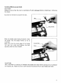
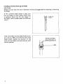
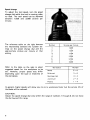
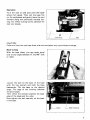
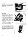
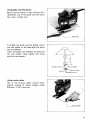
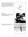
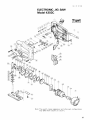
Electronic Jig Saw
MODEL 4302C
INSTRUCTION MANUAL
SPEC IFICAT IONS
L e n g t h of
stroke
26 m m
(1"l
M a x c u t t i n y capacities
Steel
60 mm
(2 3/8")
10 mm
!3/8"1
Strokes
Overall
per minute
length
weight
219 mm
(8 5/8")
2 5 ky
( 5 5 Ibs)
1,000
3.000
Manufacturer reserves the right t o change specifications w i t h o u t notice
* Note Specifications may differ from country to country
x
IMPORTANT
SAFETY INSTRUCTIONS
(For All Tools)
WARNING: WHEN USING ELECTRIC TOOLS, BASIC SAFETY PRECAUTIONS SHOULD ALWAYS BE FOLLOWED TO
REDUCE THE RISK OF FIRE, ELECTRIC SHOCK, AND PERSONAL INJURY, INCLUDING THE FOLLOWING:
READ ALL INSTRUCTIONS.
1. KEEP WORK AREA CLEAN. Cluttered areas and benches invite injuries.
2. CONSIDER WORK AREA ENVIRONMENT. Don‘t use power tools in damp
or wet locations. Keep work area well lit. Don’t expose power tools t o rain.
Don’t use tool in presence of flammable liquids or gases.
3. KEEP CHILDREN AWAY. All visitors should be kept away from work area.
Don’t let visitors contact tool or extension cord.
4. STORE IDLE TOOLS. When not in use, tools should be stored in dry, and high
or locked-up place - out of reach of children.
5. DON’T FORCE TOOL. It will do the job better and safer at the rate for which
it was intended.
6. USE RIGHT TOOL. Don’t force small tool or attachment t o do the job of a
heavy-duty tool. Don‘t use tool for purpose not intended.
7. DRESS PROPERLY. Don’t wear loose clothing or jewelry. They can be caught
in moving parts. Rubber gloves and non-skid footwear are recommended
when working outdoors. Wear protective hair covering t o contain long hair.
8. USE SAFETY GLASSES. Also use face or dust mask if cutting operation is
dusty.
9. DON’T ABUSE CORD. Never carry tool by cord or yank it t o disconnect from
receptacle. Keep cord from heat, oil, and sharp edges.
10. SECURE WORK. Use clamps or a vise t o hold work. It’s safer than using
your hand and it frees both hands t o operate tool.
11. DON‘T OVERREACH. Keep proper footing and balance at all times.
12. MAINTAIN TOOLS WITH CARE. Keep tools sharp and clean for better and
safer performance. Follow instructions for lubricating and changing accessories. Inspect tool cords periodically and if damaged, have repaired by authorized service facility. Inspect extension cords periodically and replace if
damaged. Keep handles dry, clean, and free from oil and grease.
13. DISCONNECT TOOLS. When not in use, before servicing, and when changing accessories, such as blades, bits, cutters.
2
14. REMOVE ADJUSTING KEYS AND WRENCHES. Form habit of checking t o
see that keys and adjusting wrenches are removed from tool before turning
it on.
15. AVOID UNINTENTIONAL STARTING. Don't carry plugged-in tool w i t h finger
on switch. Be sure switch is OFF when plugging in.
16. OUTDOOR USE EXTENSION CORDS. When tool is used outdoors, use only
extension cords intended for use outdoors and so marked.
17. STAY ALERT. Watch what you are doing, use common sense. Don't operate
tool when you are tired.
18. CHECK DAMAGED PARTS. Before further use of the tool, a guard or other
part that is damaged should be carefully checked t o determine that it will
operate properly and perform its intended function. Check for alignment of
moving parts, binding of moving parts, breakage of parts, mounting, and any
other conditions that may affect its operation. A guard or other part that
is damaged should be properly repaired or replaced by an authorized service center unless otherwise indicated elsewhere i n this instruction manual.
Have defective switches replaced by authorized service center. Don't use
tool if switch does not turn it on and off.
19. GUARD AGAINST ELECTRIC SHOCK. Prevent body contact with grounded
surfaces. For example; pipes, radiators, ranges, refrigerator enclosures.
20. REPLACEMENT PARTS. When servicing, use only identical replacement parts.
VOLTAGE WARNING: Before connecting the tool t o a power source (receptacle.
outlet, etc.) be sure the voltage supplied is the same as that specified on the
nameplate of the tool. A power source with voltage greater than that specified
for the tool can result i n SERIOUS INJURY t o the user - as well as damage t o
the tool. If in doubt, DO NOT PLUG IN THE TOOL. Using a power source with
voltage less than the nameplate rating is harmful t o the motor.
3
ADDITIONAL SAFETY RULES
1. Avoid cutting nails. Inspect for and remove all nails from the workpiece before operation.
2. Don't cut hollow pipe.
3. Do not cut oversize workpiece.
4. Check for the proper clearance beneath the workpiece before cutting so that
the blade will not strike the floor, workbench, etc.
5. Hold the tool firmly.
6. Make sure the blade is not contacting the workpiece before the switch is
turned on.
7. Keep hands away from moving parts.
8. When cutting through walls, floors or wherever "live" electrical wires may
be encountered, DO NOT TOUCH ANY METAL PARTS OF THE TOOL!
Hold the tool only by the insulated grasping surfaces t o prevent electric shock
if you cut through a "live" wire.
9. Do not leave the tool running. Operate the tool only when hand-held.
IO. Always switch off
and wait for the blade t o come t o a complete stop before
removing the blade from the workpiece.
11. Do not touch the blade or the workpiece immediately after operation; they
may be extremely hot and could burn your skin.
SAVE THESE INSTRUCTIONS.
4
Installing Makita jig saw blade
CAUTION :
Always be sure that the tool is switched off and unplugged before installing or removing
the blade.
Use the hex wrench to loosen the bolt.
With the blade teeth facing forward, insert
the blade into the blade holder as far as
it will go.
Make sure that the back edqe of the blade
fits into the roller and tighten the bolt
securely with the hex wrench.
J ' g saw
CAUTION :
Use a lubricant or cutting oil between the blade and roller when cutting iron or composition board, etc. Failure to do so will shorten the service life of your blade and roller.
5
Installing universal shank jig saw blade
CAUTION :
Always be sure that the tool is switched off and unplugged before installing or removing
the blade.
If the universal blade clamp is used, you
can use blades of other makes which have
a universal shank like the one shown in
the figure, with a blade width of 6.35 mm
(1/4").
I
Insert the blade into the blade holder as far
as it will go. Make sure that the end of the
blade shank reaches the bottom of the
inner s l i t and tighten the bolt securely with
the hex wrench.
6
T h e end of t h e blade
shank should reach t h e
Straight line or orbital cutting action
Conventional jig saws cut with a straight
line action, that is, the blade moves only
up and down in a straight line. Your saw
also cuts in this manner but, for softer
workpieces, an orbital cutting action can be
selected. Soft workpieces like wood and
plastic permit deep penetration of individual saw teeth. The orbital action thrusts
the blade forward on the cutting stroke
and greatly increases cutting speed over
conventional jig saws. Harder workpieces
like metal should be cut using the straight
line cutting action or a very low orbital
setting. To select straight line or orbital
cutting, adjust the number on the saw.
Position 0 - For cutting in mild steel, stainless steel and plastics.
For clean cuts in wood and plywood.
Position I - For cutting in mild steel, aluminum and hard wood.
Position I1 - For cutting in wood and plywood.
For fast cutting in aluminum and mild steel.
Position 111 - For fast cutting in wood and plywood.
Switch action
To start the tool, simply pull the trigger.
Release the trigger to stop. For continuous
operation, pull the trigger and then push in
the lock button. To stop the tool from the
locked position, pull the trigger fully, then
release it.
CAUTION :
Before plugging in the tool, always check to see that the trigger switch actuates properly
and returns to the "OFF" position when released.
7
Speed change
To adjust the tool speed, turn the speed
change dial while the tool is running under
no load. The tool speed can be adjusted
between 1,000 and 3,000 strokes per
minute.
The reference table on the right denotes
the relationship between the number settings on the speed change dial and the
approximate strokes per minute a t that
setting.
Number
Strokes per minute
1
1,000
2
1,200
1
1
1
1
3
1,700
1
1
4
2,200
1
1
5
2,700
1
1
6
Refer to the table on the right to select
suggested speed for the workpiece to be
cut. However, proper speed may differ
depending upon the type or thickness of
the workpiece.
3,000
Workpiece
Wood
Steel
Number
5-6
3-6
Stainless steel
3-4
Aluminum
2-3
Plastics
1-4
In general, higher speeds will allow you to cut a workpiece faster but the service life of
the blade will be reduced.
CAUTION :
Adjust the speed change dial only within the range of numbers 1 through 6. Do not force
the dial beyond this range.
8
Operation
Turn the tool on and wait until the blade
attains full speed. Then rest the base flat
on the workpiece and gently move the tool
forward along the previously marked cutting line. When cutting curves, advance the
tool very slowly.
I
CAUTION :
Failure to hold the tool base flush with the workpiece may cause blade breakage.
Bevel cutting
With the base tilted, you can make bevel
cuts a t any angle between 0" and 45" (left
or right).
Edge of housing
I
9
Front flush cuts
Loosen the bolt on the back of the base
with the hex wrench, then slide the base
backwards. Check the contact between the
back edge of the blade and the roller, then
secure the bolt.
Plunge cutting
Starting a cut a t other than the edge of
the workpiece without first drilling a
starting hole requires a "plunge cut". This
can be accomplished by tipping the tool
forward until the front end of the base
rests against the workpiece. Switch the tool
on and lower the back end of the tool
slowly, gradually allowing the blade to saw
through the workpiece until the base i s
able to s i t flat on the workpiece. YOUmay
then proceed forward with the cut in a
normal manner.
If using a drill for a starting hole, bore a
hole over 12 mm (1/2") in diameter. Then
insert the blade in it and proceed.
Finishing edges
To trim edges or make dimensional adjustments, run the blade lightly along the cut
edges.
For smoother cutting of plywood or other
workpieces with easily splintered surfaces,
transparent tape may be used over your
cutting line.
10
Using guide rule (Rip fence)
When cutting widths of under 150 m m (6")
repeatedly, use of the guide rule will assure
fast, clean, straight cuts.
To attach the guide rule (rip fence), secure
the rule holder to the base with the screw
(do not tighten).
Insert the guide rule between the base and
the rule holder. Now tighten the screw
with the hex wrench.
Guide
Using circular guide
Use of the circular guide insures clean,
smooth cutting of circles (radius; under
200 m m ; 7-7/8") and arcs.
\
Circular guide
11
To attach the circular guide, use the pin,
inserting it in the center hole (arrow) and
secure it with the threaded knob. Then
slide the base of the tool forwards. The
circular guide attaches to the base of the
tool in the same manner as the guide rule
(rip fence).
I
F i t pin into
this hole
Pin for
circular guide
Metal cutting
Always use a suitable coc._rnt (cutting c 1
when cutting metal. Failure to do s o will
cause significant blade wear.
The underside of the workpiece can be
greased instead of using a coolant.
12
MAINTENANCE
CAUTION :
Always be sure that the tool is switched off and unplugged before attempting to perform
inspection or maintenance.
The tool will stop when the carbon brushes wear to a certain length.
When this occurs, both carbon brushes should be replaced.
To maintain product SAFETY and RELIABILITY, repairs, carbon brush inspection and
replacement, any other maintenance or adjustment should be performed by Makita
Authorized or Factory Service Centers, always using Makita replacement parts.
ACC ESSO R I ES
CAUTION :
These accessories or attachments are recommended f o r use w i t h y o u r Makita t o o l specified in this
manual. The use o f any other accessories or attachments might present a risk of injury t o persons. The
accessories o r attachments should be used o n l y i n the proper and intended manner.
1.25mm (1/32"- 3/64")
A n exception: Universal shank jig saw blades w i t h a thickness of 1 mm and a length o f 58 mm - 82 mm (2-9/32"
- 3-7/32").
0
p
0
__-
$----
"
e-
Hex Wrench 3
Part No.
0
Guide rule (Rip fence)
Part N o . 164113-2
Circular guide assembly
Part No. 123030-5
783201-2
Jig saw blade (Packed 5 each)
Blade
type
Blade
Teeth
per inch
Part No
Effective cutting
blade length
No B
17
792469 9
6
7 0 mm (2314''I
80 m m 13 1/8"1
No H
18
792470 4
14
4 5 mni I 1 3 ' 4 " i
80 m m 13 11H"I
Na B
19
792471 2
12
6 5 m m 1 12 L 2 " I
8 0 m m 13 118 i
No B
21
7924720
12
75"
13"l
7 5 m m 13")
NO
8
22
50"
12")
80 mm 13~1/8"1
No B
23
50"
12 I
80 mm 13 118"i
No B
24
7924754
32
5 0 m m 12 I
No B
25
792476 2
9
7 5 m m 13 i
Nu H
26
7924770
9
No B
27
~~
No B
10
B
11
No H
12
No
I
I
1
792529 7
792463~1
792464 9
I
I
I
9
9
6
I
I
I
80 mm 13 1 '8"i
I
1
I
792473 8
792474 6
7924788
i
I
1
24
14
24
I
I
7 0 mm 12 3 4 i
1
50mm (2'1
(Note)
R e f e r t o t h e n e x t p a g e f o r " A p p l i c a t i o n " of e a c h b l a d e
13
0
Jig saw blade
Blade
type
No. 51
Wood and plywood
Plastics
Aluminum
Mild steel
-
1 5 - 3 mm thick
11/16" - 118")
ti
1 - 6 mm thick
13/64" - 114")
1 - 3 mm thlck
13/64" - 118")
-
-
Feature
Also ideal for cutting
stainless steel.
~
No. 58
4 - 60 mm thick
15/32" - 2 318")
4 - 60 mm thick
15/32" - 2 318")
S
No 59
For fast cutting.
For fast finish work
No.
8-10
For fast finish work,
especially in plywood
No.
8-11
For fast finish work
No.
8-12
For fast finish work
No.
8-13
For roughing-in work
No
8-14
Ideal for cutting
thin materials.
No.
Ideal for cutting
thin materials
8-15
No.
8-16
For fast cutting
No.
8-17
Ideal for scroll cutting.
No.
8-18
Ideal for scroll cutting
~
No.
8-19
3 - 30 mm thick
1118" - 1~118")
No.
8-21
No.
B-22
I
I
3 - 3 0 mm thick
1118'' - l - l / 8 " )
H
3 - 55 mm thick
1118" - 2-118")
-
-
3
10 mm thick
1118'' - 318")
For finish work.
especially in plastics
~
H
1 5 - 3 m m thick
11116" - 118")
1 - 6 mm thick
13/64" - 114")
1 - 3 mm thick
13/64" - 118")
H
No.
8-23
3 - 6 mm thick
1118'' - 114")
-
3
- 10 mm thick
1118" - 318")
3 - 6 mm thick
1118" - 114")
H
No.
8-24
1 - 3 mm thick
13/64" - 118")
-
0 5 - 3 mm thick
11164" - 118")
0 5 - 2 mm thick
11/64" - 5/64"]
H
No.
8-25
No.
8-26
No
8-27
3 - 55 mm thick
1118" - 2-1/8"1
H
3 - 55 mm thick
1118'' - 2~118")
H
3 - 30 mm thick
1118" - 1 ~ 1 1 8 " )
3 - 10 mm thick
1118"
318")
3 - 55 mm thick
1118" - 2~118")
H
3 - 55 mm thick
1118'' - 2-118")
H
3 - 30 mm thick
1118" -. 1 - 1 / 8 " )
3
1.5 - 3 mm thick
11/16" - 118")
1 - 6 mm thick
13/64" - 114")
H
NOTE:
H" s t a n d s f o r h a r d m a t e r i a l s
"S" s t a n d s f o r soft m a t e r i a l s
14
Cuts o n down stroke.
Splinter~freeon finish side.
- 10 mm thick
1118" - 318")
1 - 3 mm thick
13164" - 118")
Also ideal for cutting
stainless steel.
Also ideal for cutting
stainless steel.
Also ideal for cutting
stainless steel
Ideal for cutting
thick materials
Ideal for scroll cutting
Ideal for scroll cutting.
Oct
01 '87 EN
ELECTRONIC JIG SAW
Model 4302C
Note The switch. noise suppressor and other part configurations
may differ from country to country
15
MODEL
4302C
ITEM
NO
NO
USED
M
e
3
1
1
1
4
1
5
6
1
1
1
4
7
6
9
10
11
1
1
12
1
1
13
1
14
17
1
1
3
1
1
1
1
1
1
1
1
1
1
1
1
1s
19
20
21
22
23
24
25
26
27
26
29
30
31
32
1
33
34
35
36
1
1
1
1
37
38
39
1
40
1
41
I
1
1
1
-
Oct
,,?&,
DESCRIPTION
Switch
42
Housing Set IWilh Item 611
P," 5
P," 5
flat Washer 5
Roller
Flat Washer 5
Pin 6
P," 5
Comprerrlo" SP""9 4
Sprfng Guide
Sleel Ball 5 6
spacer
Pl" 4
Label
Pan Head Screw M 5 x 4 5 iWiih Washer)
Label
Steel Ball 4
ComprerPlon s p m g 4
Lever 25
Slider
Hex Sockel Head Bolt M 6 x 6
Dust Plate
Dust Seal
Thin Washer 9
Fiber Washer 9
Needle Bearing 607
Flat Washer 6
Pin 6
Flat Washer 6
Bare Holder
Base
Clamp Plate
Hex Socket Head Bolt M 4 x 1 6 iW fh Washer)
FIELD ASSEMBLV
Ball Bearing 608LB
Insulation Wsrher
ARMATURE ASSEMBLY
iWith Item 36
421
Fan 66
43
1
1
44
1
Bearing Care
Flay Washer 8
45
1
Needle Bearing 610
46
47
46
49
1
Needle Beering 610
1
Helical Gear 6 5
Flat Washer 35
I
1
50
51
1
52
1
53
54
55
1
1
56
1
1
2
1
57
56
59
60
61
62
63
64
65
66
67
66
69
70
71
72
73
74
75
76
77
76
79
60
I
Purh Plate
flax Washer 6
Pin 6
1
I
CO"f,Ole,
1
PrOfeCfor
6
1
I
1
1
1
1
1
1
1
1
1
1
1
2
2
2
1
8 7 US
Ball Bearing 606LB
Flat Washer 3 5
Balance Plate
Balance Plate
Flat Washer 2 6
Flat Washer 6
Clank
Pan Head Screw M 5 x 1 6 (With Warheri
Name Plate
Pan Head Screw M 5 1 2 5 (With Warher)
HDUIing Set iWilh Item 2)
Rubber Pin 4
Retaining Ring S 6
P," 4
Aetal"e,
Roller
Sponge Sheet
D"*l Plate
Slop Ring E 3
P," 5
Cord Guard
Cord
Strain Relief
Pan Head Screw M4x16 lWith Washer)
Carbon Brush
Brush Holder
Speed Control
Screw 3 2
1
06
DESCRIPTION
- -
Nofe The switch and Other pari s ~ e c 1 1 1 c a l i o nmay
s
differ from country 10 country
MAKITA LIMITEDONE YEAR WARRANTY
Warranty Policy
Every Maklta tool IS thorou ly inspected and teated before leaving the factory. It is warranted to
be free of defects from w o r k i s h i p and materials fo, the period of ONE YEAR from the date of
original purchue. Should any trouble develop duriing this one-year period, return the COMPLETE
tool, freight prepaid, to one of Makits's Factory or Authorized Service Centen. If inspection show
the trouble is caused by defective workmanship 01 material, Makita will repair (01 at OUI option,
replace) without charge.
??us Warranty does not apply where:
repairs have been made or allemoted by others:
npairs are required because of normal wear and tear.
The 1001 has been abused, misused or improperly mamtained;
alterations have been made to the tool.
:
i
I
IN '40 t V t W SHALL MAKITA Bb LlABLL kOR ANY INDIRkCT INCIDENTAL OR CONS t Q l b N T I A L DAMAGES FROM THE SALE OR USE Of.
THE PRODUCT THIS DISCLAIMER
APPLIbS BOTH DURING AND AFTER THE TERM Ob THIS WARRANTY
MAKITA DISCLAIMS LIABILITY t O R ANY IMPLIFD WARRANTILS. INCLUDINC, IMPLltD
WARRANTltS OF 'MFRCHANTABILITY' AND 'FITNESS FOR A SPtClFlC PURPOSF."
AFTCRTHEONFrYFARTFRMOiTHISWARRANTY
Tlus Warranty gives you specific legal rights, and you may also have other rights which vary from
state to slate. Some states do not allow the exclusion 01 limitation of incidental or consequential
damages. so the above Imitation or exclusion may not apply to you. Some states do not allow
limitation on how long an implied warranty I~sts.so the above limitation may not apply to you.
:
1
Makita Corporation
3-11-8, Sumiyoshi-cho,
Anjo, Aichi 446 Japan
883533A060
PRINTED IN JAPAN
1991 - 8 - N