1
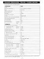
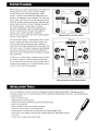
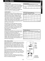
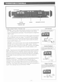
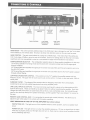
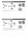
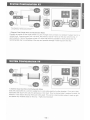
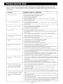
BLAUPUNKT SPECIFICATIONS - THA1350, 1 CHANNEL AMPLIFIER All power ratings conform to CEA-2006 standards. PARAMETER/FEATURE THA1350 Channels 1 Size ( W x H x Dj without end caps 9.9 x 1.7 x 16.6 inches (251 x 43 x 422mm) Weight 9.9 Ibs. (4.5 kg) Spade screw speaker terminals? YES Maximum terminal wire size 14 ga Subsonic filter YES (10 Hz) Separate fronVrear or leIVright gains? N/A Fuse Type ATC spade -Three 30A Speaker short, short to +12V, and short to ground protection? YES High, low, and reverse voltage protection? YES Power output transistors BTL Power supply transistors MOSFET Minimum speaker impedance (non-bridged) 2 ohms (bridged) N/A PERFORMANCE DATA Rated power output @0.1 % THD, 14.4V (CEA-2006) 1 channel into 4 ohms / 2 ohms (watts rms) 1 x 350 W 1 channel into 4 ohms (watts rms) 1 x 400 W Max Dynamic Power (watts rms) 450W Total Harmonic Distortion @full power 0.03% THD Signal/Noise ratio (gain controls in center) Measured @1 watt / 1 kHz dBA >80 Measured @full rated power (0.1 % THO) dBA >104 Damping factor >100 Frequency response (fUll-range mode) 10 - 30,000 Hz High-pass crossover frequency limits N/A Low-pass crossover frequency limits 50 Hz - 250 Hz (variable), 12dB/oct Bass Boost Variable (0-12db) Input impedance 10 kohms Input signal voltage control range 0.3 - 6.0 vrms Current Draw @138 VDC (typical values @Xwatts / Efficiency %) @full rated power, unbridged (@4 ohms) 45 A (50%) @33% rated power, unbridged (@4 ohms) 25 A (35%) @idle (@4 ohms) 2A Minimum battery voltage to maintain rated power 13.8 VDC Usable battery voltage 10-16VOC Trigger line voltage range 10-16VDC Trigger line current draw < 20 mA Turn on delay time @ 2.0 seconds Thermal shutoff temperature (average heat-sink temp) @85" C (185 F) NOTE: DUE TO ONGOING PRODUCT IMPROVEMENTS, DESIGN AND SPECIFICATIONS ARE SUBJECT TO CHANGE WITHOUT ADVANCED NOTICE TO THE CONSUMER OR RETAILER. - 1 - ASSEMBLY , & MOUNTING • T • T T 1 T -2- THANK You FOR CHOOSING BLAUPUNKT! Congratulations! You are the now the owner of an exceptional car audio amplifier from the audio enthusiasts at Blaupunkt. Our engineering staff has spent considerable time refining our THA series amplifiers in order to introduce great sound to the consumer at an affordable price. With these products we focus on sonic performance but balanced with rugged design and flexible installation. Not only do we offer you a great product but also a supportive owners manual. This manual can be used as a teaching guide due to its brief, but informative, explanations of amplifier and system design. We are also very concerned about the end consumer using proper installation techniques for the highest performance possible from their new audio products. MOST important to us are the concerns with safety and the installation process. Since our Blaupunkt retail dealers have the tools and experience for an optimized and safe installation, we always recommend they do the final vehicle integration. But, should you choose to install these products yourself, please take the time to read this manual completely and abide by all precautions. AMPLIFIER BENEFITS & FEATURES There is a constant push for entry level amps to "play with the big dogs" yet for a low price point. Rarely are they able to do so .... until now. Rock solid Class AS designs ensure "in your face" sound with little fear for reliability or performance. The rugged designs of the THA amp line, and their remarkable input frequency and gain setting flexibility, enable nearly any system configuration. Fat power and speaker leads make sure all that power going in comes out the best sound possible. Should something go wrong in the installation, have no fear. Protection for output short circuits and short to grounds or 12 volts are all covered and a safety "Protect" light lets you know. Peace of mind, and big power, at low price points ... look no further. • Real, RMS watts. No need for "bogus" watts. This is the real stuff in a great am p so there is no need to exaggerate - it does what it says. • Reinforced Class AS designs with reinforced output stages ensure solid performance and reliability. • Big heat sinks to ensure adequate heat dissipation regardless of the load (they look cool too). • Monster size, gold plated power and speaker terminals for reliable, low resistance connections. • Protection LED for notification should the unit shut down due to installation problems. • Wide range input voltages of O.3-6.0Vrms. • Continuously variable crossover frequency settings. • 2 ohm output stable (unbridged mode) -3- SAFETY CONCERNS We always recommend you have your Blaupunkt amplifiers professionally installed but the installation process is often so easy that the average consumer can achieve success with little trouble. Regardless of the person installing, you should be sure to review the following points before proceeding with the installation: • READ THE MANUAL! Understanding the product and installation limitations before lifting a screwdriver. • WEAR SAFElY GLASSES AT ALL TIMES - Flying debris are always dangerous. • PROTECT THE VEHICLE - Always disconnect the negative battery cable before starting any kind of installation work. This prevents a possible high current electrical short (potential fires). • HEAT - Keep all audio components away from nearby hot vehicle components that heat up over time such as hoses, high current wires, and braking system components. • GIVE YOURSELF LOTS OF TIME - Rushing to complete an installation nearly always ends up with problems. • DO NOT LISTEN AT HIGH SOUND LEVELS FOR A PROLONGED TIME - these amplifiers, used with high efficiency speakers from ANY manufacturer, have the potential to cause permanent hearing loss after listening at maximum volume levels for several hours. INSTALLATION WARNINGS! Before disassembling your beautiful new car you need some basic installation knowledge and skill with common hand and power tools. Following such basic installation tips and warnings will prevent possible damage to the vehicle and also prevent possible fires. • AGAIN ... READ THE MANUAL! There is a lot of helpful information in this manual that will save time and prevent problems later. • COVER THE VEHICLE WORK AREAS - Use fender covers or blankets to protect the work areas from scratches or dings. • DISCONNECT THE (-) LEAD ON THE BATIERY - No sparks or fires please! • "REVIEW" THE INSTALLATION - Before using any tools or moving vehicle components, take five minutes to review the installation intentions (e.g., verify that an amplifier will fit in an area of a car before tearing out all the interior). • "REVIEW" THE VEHICLE - Before drilling any holes or cutting into any surfaces, make sure there are no fuel or hydraulic lines behind the surfaces. Also make sure there are no wires routed directly behind or near the desired mounting area (remember...screws can often extend 1-2 inches behind the mounting surface). • ENSURE PROPER FIT - Before cutting or drilling, make sure the amplifier will physically fit in its desired location. Check for clearance around rear deck torsion bars or other structural elements. • EVERY CAR IS ASSEMBLED DIFFERENT - Every auto manufacturer uses different assembly techniques. Take care in removing/modifying all trim panels and mounting surfaces since they often use unique screws or snap fasteners that are difficult to replace if they are lost or broken. • BE CAREFUL WITH CABLE ROUTING - When routing audio cables, make sure RCA and speaker wires are routed away from high current power lines for audio amplifiers and vehicle systems lines when possible. This will help prevent noises from creeping into the audio system, plus prevent potential damage to the vehicle wiring itself. • BE CAREFUL WITH ALL CONNECTIONS - When making connections, make sure each connection is clean and properly secured. Observe all polarity markings carefully to ensure proper end performance. • CAUTION - FUEL TANKS AND FUEL LINES ARE NOW LOCATED DIRECTLY BENEATH THE REAR DECK IN MANY CARS - CHECK FOR ADEQUATE CLEARANCE BEFORE EVEN CONSIDERING SUCH A MOUNTING LOCATION! -4- SYSTEM PLANNING Before wiring up an audio system that may not achieve the sound quality you want, be sure to choose a system concept that fits your listening requirements. Basic systems, a receiver with internal 4x20 watts and 4 coax speakers, are adequate for many listeners. But, when you want to really "feel" the music, you will need some kind of subwoofer amplifier/speaker combination. Although many people might jump into an "add-on" amplifier to power to rear coaxial speakers, a better choice is usually a subwoofer amp/speaker system that supplements the existing 4 speaker system as shown in the adjacent drawing. Such a system provides a surprising improvement in sound quality due to the usually dramatic increase in bass response. The next dramatic step up in performance is with a "multichannel" system that offers more dynamic range in the mids and highs due to higher power plus more bass response due to multiple woofers and/or more power. But, with such a system, the stereo image and overall listening experience usually becomes much more life-like due to better tonal quality midrange/tweeter speakers and usually better placement. ~ '"ir ll ge .=R=an=ge===Fu=II=.R=an= =l ~I......-H(j] Subwoofer Full·Range Supplementary subwoofer system Receiver ~ r-------~ / To build such a system though, complexity goes up due to the addition of passive or active crossovers which take time to install and may inject noise into the system due to potential noise signal pick up. The results though of such a system can be dramatically pleasing. Sat Amplifier ; / 7. 5W) \1Z~ Passive X-over Sub Amplifier (2x125 W) Subwoofers High performance multi-channel system INSTALLATION TOOLS For most installations, simple hand tools are adequate to install an aftermarket amplifier. Depending upon the mounting locations used, you will need power tools for drilling and cutting plastics and metal. A good starting list is summarized below: • Tape measure and ruler • Marking pen and starting punch • Phillips and flat blade screwdrivers (small and medium sizes) • Nylon wire bundle ties • Pliers: standard vice-grip and needle nose styles • Light-duty trim pry-bar for removing door trim • Cutting shears or nibbling tool for cutting thin and medium gauger metal • Wire cutters, wire strippers, electrical tape, crimping pliers and appropriate crimp-on terminals • Power drill with appropriate sized drill bits -5- VEHICLE WIRING VEHICLE FUSING For safety purposes, a high current fuse (or circuit breaker) MUST be installed in line with the amplifiers(s) immediately at the battery to prevent vehicle damage should the battery line in advertently shorted to the vehicle chassis. The chart at the right shows the recommended master fuse sizes for an average audio system with noted "rms" output power levels. SYSTEM FUSE CHART (Fuse size for total amplifier system power in "rms" watts) Fuse Size (in amps) POWER WIRING Most vehicles built since 1990 have adequate current capability for your amplifier. Except for systems above about 500 W rms, the factory charging system and battery should easily support it if properly installed. Proper wire size must be chosen to ensure adequate current delivery to the amp. Wire size (gauge) of the cables need to increase in size for higher power systems. 0JVire sizes larger than those noted are usually a waste of time and money since they offer Little or no performance improvements.) 100W 200W SOOW 1000W 20A 30A 50A 100 A SYSTEM POWER AND GROUND WIRE CHART ryvire gauge for total system in 'rms' watts) 100W 200W SOOW 1000W 5 fl./1.S m 12 10 8 4 10ft./3.0m 12 10 8 4 15 ft. 14.5 m 10 8 6 2 20 fl. 16.0 m 10 8 6 2 25 ft. 17.5 m 10 8 4 o orOO WIRE LENGTH Wire diameter must increase (decreased wire gauge number) for higher power systems. For long wire runs the wire diameter must also increase. The wire sizes noted allow for a maximum 0.5 volts DC drop over the give wire run which results in Sound Pressure Level drops inaudible to the average listener. SPEAKER WIRING As with power wire, speaker wire size (gauge) changes with the power required and the length of the wire run. The speaker wire chart shows the minimum recommended wire size for a single audio output channel driving a loudspeaker at a given distance with a maximum power loss of 0.5 dB, the threshold of audibility. 0JVire sizes larger than those noted are usually a waste of time and money since they offer little or no performance improvements.) LOUDSPEAKER WIRE CHART ryvire gauge per loudspeakerlspeaker power in "rms" watts) WIRE LENGTH 20W SOW 100W 200W 5 fl./1.5 m 18 16 16 16 10 ft. I 3.0 m 18 16 16 16 15ft./4.5m 16 16 16 14 20 ft. 16.0 m 16 16 16 14 25 ft. I 7.5 m 16 16 14 12 FINAL VEHICLE WIRING Current requirements for an upgraded audio system dictate a dedicated power line be run from the amplifier directly to the battery of the vehicle. This line should NOT be run to the fuse panel of the vehicle but directly to the battery. DO NOT run to the alternator either. There MUST be a fuse installed at the battery with adequate amperage as shown in the chart above. As for the final signal wiring, be sure to route the audio cables down the side of the car opposite the power lines to avoid noise pick up from the lines. Also, try to route all audio cables away from noise sources such as engine computers and ABS brake computers. Proper power grounding is important to insure adequate current flow. Be sure to grind the surface clean of all paint to ensure a solid electrical connection. -6- Battery Connector Grommet To prevent damage to power wire Power Wire Power Antenna Turn·On Wire (10 gauge wire or larger) (18·20 gauge wire) Speaker Wires or RCA Cables / Amplifier Ground Screw Drill 1/8" hole in chassis sheet metal Use the same ground if using multiple amplifiers CONNECTIONS & CONTROLS POWER CONNECTIONS & TRIGGER LINE FUSES SPEAKER OUTPUTS POWER CONNECTIONS & TRIGGER LINE: GROUND - This is the high current ground connection to the chassis of the car. It should be fastened to a clean ground connection in the vehicle, capable of handling high current loads. This wire should be no longer than 3 feet (1 meter) +12V Terminal Connect directly to the vehicle battery (+) terminal with 10 gage wire (minimum) +12v - A high current line run direct from the batter is highly recommended to insure adequate current and voltage. This line MUST be run through a dedicated fuse of some kind and this fuse should be located immediately next to the power source. This in-line fuse is used to protect the vehicle should a short to chassis occur. TRIGGER - This line tells the amp to turn on and is remotely switched from the radio which normally provides an amp "trigger" output. This line is required to go "high" (+ 12V) to turn on the amp. If this line is not available, use the power antenna line trigger which is normally available in most radios. FUSES - These fuses are only for catastrophic situations should the amplifier begin to self-destruct or incur installation situations where gross amounts of current are being reqUired from the amp beyond its design limits. Although another fuse should be installed inline with the high power line at the battery, these amplifier mounted fuses MUST remain in the circuit to protect the amplifier. SPEAKER OUTPUTS - The amplifier is connected to appropriate impedance speakers via these leads. It is IMPERATIVE that these leads NOT be connected or touch the vehicle chassis in any way or the amplifier will be damaged. The (+) and (-) leads of the amp are in no way inter-connected to one another. Also, NONE of the leads can touch each other, touch ground, or touch +12V or damage may occur to the amp or vehicle. Ground Terminal Connect to a good chassis ground. The ground connection should be clean. unpainted metal to provide a good electrical connection. . ' kJr -- co-.. 10 WI,. 5<_ ..... Con...c:lor o..llB·holIt ~. ..- Trigger Terminal Connect the radio power antenna lead from the receiver to the trigger terminal. This turns the amplifier on whenever the receiver is turned on. -7- CONNECTIONS & CONTROLS BASS BOOST CONTROL CONFIGURATION SWITCH GAIN CONTROL SUBSONIC FILTER CONTROL LOW PASS CROSSOVER CONTROL REMOTE GAIN CONTROL JACK LINE LEVEL INPUTS & OUTPUTS BASS BOOST - This control provides additional bass in the 45Hz area to give a stronger low end "feel" to the bass. Once switched on, this will also allow the amp to be driven into distortion sooner so the user must be aware. GAIN CONTROL - The gain control allows for a range of O.3-6Volts input. This means that if the setting is a O.3V, it only takes O.3Volts to drive the amp to full output. (Such a low setting allows for the amp to be easily overdriven and more susceptible to noise so a mid-position is highly recommended for most radios.) CONFIGURATION SELECTOR - The configuration selector allows for three possible installations for this amp: (1) The amp operates in full range mode and the AUX-OUT connectors simply loop the full range signal through unaltered. (2) The amp filters and amplifies the signal per the chosen low-pass filters and this same signal is sent on to the AUX-OUT jacks. (3) The amp filters and amplifies the signal per the chosen low-pass filters bu1 the AUX-OUT signal is passed through withou1 filtering. LOW-PASS CROSSOVER CONTROL - If the control is in the "LP" position the amplifier passes only low frequency sound. The upper limit for such sound is set via this control. For bass, a value just below 1OOHz is usually best. SUBSONIC FILTER - The subsonic filter prevents ultra low frequency information from unneccesarily overdriving the amp at sub-audible frequencies thus saving amplifier power. LINE LEVEL INPUTS & OUTPUTS - The most commonly used Inputs & outputs in the aftermarket are RCA type line level inputs. These can handle up to about 6 Volts rms without overdriving the amplifier. Such high voltages are rarely found from car audio head units so this is a very comfortable value. Bu1, should the use need to drive the amp directly from speaker level leads, use the supplied "High Level Adapter" to connect to the amp. REMOTE GAIN CONTROL JACK - For connecting the remote gain control (included). This allows you to adjust the gain while seated in the vehicle with the system operating. LIGHT INDICATOR ON THE TOP OF THE AMPLIFIER (not shown above) PROTECTION LED - This light turns on if the amplifier senses a severe problem, such as a speaker short circuit. POWER ON LED - This light will turn on when the amplifier receives a + 12V turn on signal from the radio. If the amp is properly wired, but the light does not turn on, there may be a short circuit condition that the amp is protecting itself from. -8- SYSTEM CONFIGURATION # 1 F"'·Range - , =I-H 4 0 :.~' I .. 0 I : I ~~_.- ,$Ingle Coil Subwool" Furl-Range 1 Channel, Single Coil Subwoofer Mode This configuration is the most common usage as a straight ahead subwoofer amplifier. SYSTEM CONFIGURATION #2 ..... Full-Range 0 I I - - 2 ,Dual Cod Sobwoofer (coils In senes) .- o - : - e Full-Range . . 1 Channel, Dual Voice Coil Subwoofer Mode This configuration is able to drive a dual voice coil subwoofer if the coils are dual 8 ohm, thus 4 ohms in parallel. Although the amp is able to run into a 2 ohm load (DVG subwoofer with coils in parallel), we do not recommend it for prolonged times due to potential overheating. -9- SYSTEM CONFIGURATION #3 Full.Range - - 0: ::-;--t :'" - ~ 4 ,Single Cod Subwoof"", 'This confi\iluratJon is possible. but nol recommended for prolonged listening' thermal protectlOrl wiU occur. 1 Channel, Dual, Single Voice Coil Subwoofer Mode Possibly as popular as the single woofer is a pair of single voice coil subs in a standard "wedge" box for a vehicle trunk. Assuming each coil is 8 ohms, this places a load of 4 ohms on the amp which is fine. If each woofer is 4 ohms, this places a load of 2 ohms total which is possible for short periods but not recommended due to overheating of the amp and possible damage if used long term like this. SYSTEM CONFIGURATION #4 Full-Range 4 ,Dual COIl Subwoofers (coils in parallel) 1 channel, Dual, Dual Voice Coil Subwoofer Mode Dual, DVe subwoofers in a common wedge box in a car works great but is often forgotten. For a pair of DVe subwoofers with dual 4 ohm coils, this produces a 2 ohm load. Now, by placing these 2 speakers in series, we achieve a 4 ohm load to the amp which just works great! This can be a real pounder system if wired up right and places only moderate loads on the amp. Highly recommended! - 10- TROUBLE-SHOOTING GUIDE Below is a basic trouble-shooting guide to assist in seeking out and correcting a problem that may occur in the installation process. Although lengthy, this chart cannot address every single problem possible but mainly the ones most common. SYMPTOM PROBABLE CAUSE OR CORRECTION No power (power light not on) o Check connections to amps + 12 volt, ground, and remote lines. o Use voltmeter to verify voltages are at terminals of amp. o Check main power connection at battery. o Check fuse in power line at battery. o Disconnect all speakers but not power lines - if unit then turns on, a speaker short or speaker line touching vehicle chassis is likely. Power but no sound (power light is on) • Check all input cable lines for connection. o Disconnect speakers from amp, test speaker lines with digital voltmeter to verify >2 ohms per channel (non-bridged mode). No sound from one channel or entire side • Check radio's balance and fader control positions - verify they are at center. o Check speaker connections at amp and speaker. o Check input leads for connection to amp. Very low sound level • Verify radio balance and fader controls are at center positions. • Check amplifier's input gain control setting - adjust for higher output levels if necessary (gain settings closer to 0.3 volts). o Receiver may have very low output voltage levels - a step up "line driver" may have to be used. Power amplifier turns on and oft repeatedly (motor·boating sound) o Make sure power connections at batter are tight. • Verify battery voltage is >11.5 volts DC (12.5-15V engine on) at amplifier with engine oft. o Check all radio and amplifier ground connections. Amplifier turns oft during loud or distorted passages o • o o Amplifier perlorms fine but gets very hot to the touch • Input gain control too high - lower accordingly (closer to 4.0 volt setting). o Verify speaker loads >2 ohms on all channels (non-bridged mode). • Verify the mounting location allows for free air movement around the amp. Preferably, the amp should be mounted with fins up and down so rising heat moves quickly away from amp. f\mplifier turn-on/turn-off pops or noises o "turn on race" - disconnect trigger from radio and turn on/off via a wire jumper to power terminal. If noise goes away, the radio is turning on/oft too slowly. This is radio problem and can only be corrected with outboard turn-on delay relay system. o Radio "thump" - disconnect the RCA input lines to the amp and turn on/oft via radio trigger. If noise goes away without RCA lines connected, the radio is sending pops out through RCA lines. This is a radio problem and can only be corrected with outboard turn-on delay relay system. Cracking noises on AM/FM radio but not on tape or cd. o Ensure the problem is "radiated noise" by placing a portable FM radio near the car engine. If noise is picked up, then it is a vehicle problem and not your system. Research to isolate the source and properl shield or bypass. • Are spark plugs and wires> 3 years old? These can often radiate substantial noise when old. • Verify the engine block has a good ground connection to chassis ground. o Verify the engine compartment hood is grounded to vehicle chassis via a braided grounding strap. Whining noise. engine running. varies in pitch or loudness with engine speed, AND varies with radio volurT'e control setting (this is generally a RADIO installation problem) o Verify all power and ground connections are clean at radio. • Re-route radio power and ground so they are sourced from same connections back at amplifier (this is called a "common" ground). • Check all ground connections to ensure clean surlaces that have all paint removed and also not oxidation buildup over time. o Verify there is some kind of power filtering choke assembly at back of radio. If not, install one. Whining noise. engine running, varies in pitch or loudness with engine speed, BUT, DOES NOT vary with md;o volume control setting (this is generally an amplifier installation problem) • Check battery ground connections at chassis are clean and tight, scraped free of oxidation, paint, and grease. oRe-route radio power and ground so they are sourced from same connections back at amplifier (this is Input stage being over-driven - lower input gain (closer to 4 volt setting). Verify battery voltage is >11 .5 volts DC at amplifier with engine oft. Check all radio and amplifier ground connections. Verify speaker loads >2 ohms on all channels (non-bridged mode). called a "common" ground). o Bypass all equipment between radio and amp (e.g., equalizers) directly connecting radio. If noise goes away, signal processor has problem. • Check for signal level "ground loops" - disconnect the outer shield of the RCA cable at one end of the cable (e.g., radio end). If noise goes away, modify cables accordingly. There are voltage difterences at the ground connections of the components and these are NOT correctable any other way than such shield cutting or an outboard "ground loop isolator" which is a small transformer. - 11 - GUARANTEE (EUROPEAN UNION) I We provide a manufacturer guarantee for our products bought within the European Union. You can view the guarantee conditions at www.blaupunkt.de or ask for them directly at: Blaupunkt GmbH Hotline Robert Bosch Str. 200 0-31139 Hildesheim Germany LIMITED WARRANTY (UNITED STATES ONLY) Robert Bosch Corporation (for products sold in the United States) warrants new Blaupunkt car audio products distributed in the United States through authorized Blaupunkt dealers, or which are imported as original vehicle equipment by the automobile manufacturer, to be free from defects in material and workmanship, in accordance with the following terms and conditions: For twelve (12) months after delivery to you, the original consumer purchaser, we will repair or at our option replace at no charge to you any car audio product which, under normal conditions of use and service, proves to be defective in materials or workmanship. However, this warranty does not cover expenses incurred in the removal or reinstallation of any car audio product, whether or not proven defective, and does not cover products not purchased from an authorized Blaupunkt dealer. This warranty is limited to the original consumer purchaser and is not transferable. Repaired and replacement car audio products shall assume the identity of the original for purpose of this warranty and this warranty shall not be extended with respect to such products. To obtain performance of this warranty, contact the nearest Blaupunkt authorized repair facility or our nearest office. A dated purchase receipt or other proof that the product is within the warranty period will be required in order to honor your claim. Carefully pack the unit and ship prepaid to the servicing location. For further information: In the United States, write to the Robert Bosch Corporation, 2800 South 25th Avenue, Broadview, Illinois, 60155, attention Blaupunkt Customer Service Department or call 1-800-950-2528. Specifically excluded from this warranty are failures caused by misuse, neglect, abuse, improper operation or installation, dropping or damaging a radio faceplate, unauthorized service or parts, or failure to follow maintenance instructions or perform normal maintenance activities. Normal maintenance activities for car audio products include but are not limited to cleaning, such as cleaning radio faceplate connectors and tape heads, tape player head demagnetization and tape player lubrication, compact disc and lens cleaning, and other minor maintenance activities and adjustments that are outlined in the owner's manual or that are normally required for continued proper operation. Also excluded from this warranty are the correction of improper installation and the elimination of any external electromagnetic interference. THIS WARRANTY SETS FORTH YOUR EXCLUSIVE REMEDIES WITH RESPECT TO THE PRODUCTS COVERED BY IT. WE SHALL NOT BE LIABLE FOR ANY INCIDENTAL, CONSEQUENTIAL, SPECIAL OR PUNITIVE DAMAGES ARISING FROM THE SALE OR USE OF ANY BLAUPUNKT CAR AUDIO PRODUCTS, WHETHER SUCH CLAIM IS IN CONTRACT OR TORT. NO ATIEMPT TO ALTER, MODIFY, OR AMEND THIS WARRANTY SHALL BE EFFECTIVE UNLESS AUTHORIZED IN WRITING BY AN OFFICER OF ROBERT BOSCH CORPORATION. THIS WARRANTY is IN LIEU OF ALL OTHER WARRANTiES OR REPRESENTATIONS, EXPRESS OR IMPLIED, INCLUDING ANY WARRANTY IMPLIED BY LAW, WHETHER FOR MERCHANTABILITY OR FITNESS FOR A PARTICULAR PURPOSE OR OTHERWISE AND SHALL BE EFFECTIVE ONLY FOR THE PERIOD THAT THIS EXPRESS WARRANTY IS EFFECTIVE. ANY IMPLIED WARRANTY SHALL BE LIMITED IN DURATION TO ONE YEAR FROM DATE OF PURCHASE. SOME STATES IN THE U.S. DO NOT ALLOW LIMITATIONS ON HOW LONG IMPLIED WARRANTY LASTS. SO THE ABOVE LIMITATIONS MAY NOT APPLY TO YOU. THIS LIMITED WARRANTY GIVES YOU SPECIFIC LEGAL RIGHTS, AND YOU MAY ALSO HAVE OTHER RIGHTS WHICH VARY FROM STATE TO STATE IN THE U.S. In the event any provision, or any part or portions of this warranty shall be held invalid, void or otherwise unenforceable, such holding shall not affect the remaining part or portions of that provision or any other provision hereof. ROBERT BOSCH CORPORATION BLAUPUNKT CUSTOMER SERVICE 2800 SOUTH 25TH AVENUE BROADVIEW, IL 60155 TEL: 1-800-950-2528 BLAUPUNKT TECHNICAL SUPPORT Blaupunkt is constantly working on making the operating instructions clearer and easier to understand. However, if you still have questions on how to operate the amplifier, please contact your dealer or the telephone hotline for your country, -12 - MERCI D'AVOIR CHOISI BLAUPUNKT! Felicitations I Vous etes maintenant proprietaire d'un amplificateur pour autoradio exceptionnel, produit par les audiophiles enthousiastes de Blaupunkt. Notre equipe d'ingenieurs a passe un temps considerable a raffiner notre ligne d'amplificateurs THA, afin de vous apporter un son remarquable un prix abordable. Nous nous concentrons avec ces produits sur la performance sonore, alliee une conception solide et une installation flexible. a a a Nous vous offrons non seulement un produit remarquable, mais egalement un manuel du proprietaire pratique. Ce manuel peut etre utilise com me un guide d'apprentissage, grace ses explications breves mais informatives sur la conception des systemes et des amplificateurs. Nous voulons egalement nous assurer que Ie consommateur utilisera des techniques d'installation appropriees afin de tirer la meilleure performance possible de leur nouveau materiel audio. Nos preoccupations MAJEURES sont la securite et Ie processus d'installation. Nos revendeurs Blaupunkt ayant les outils et I'experience necessaires a une installation sOre et optimale, nous recommandons toujours qu'ils se chargent de I'integration finale au vehicule. Toutefois, si vous decidez d'installer ces produits vousmeme, veuillez prendre Ie temps de lire ce manuel jusqu'au bout et d'en observer toutes les precautions. a AVANTAGES ET PROPRIETES DES AMPLIFICATEURS THA Les amplis debutants sont toujours ambitieux de "jouer avec les grands" tout en restant pas chers. Mais ils I'ont rarement reussi ... jusqu'a present. a La conception de Classe AB solide comme un roc assure un son qui vous "tape la figure" sans crainte pour sa flabilite ou sa performance. La conception robuste de la serie des amplis THA, leur remarquable frequence d'entree et leur flexibilite du reglage d'accroissement permettent pratiquement toutes les configurations possibles du systeme. Les fils epais du bloc d'alimentation et des enceintes assurent que toute la puissance qui rentre a I'interieur ressorte sous forme du meilleur son possible. Si quelque chose ne va pas pendant I'installation, ne vous inquietez pas. Le systeme est protege contre les courts-circuits de sortie, de mise a la terre et du circuit 12 volts; en outre, un voyant de securite vous previent du probleme. La paix en I'ame, une grande puissance, et encore pas tres cher ... ne cherchez pas davantage. • Des watts efficaces reels. Pas besoin de watts "bidon". C'est du vrai son dans un ampli super. done on n'a pas besoin d'exagerer - ya fait ce que ya dit. • Une conception plus robuste de Classe AB avec des etages de sortie renforces assure une performance solide et la fiabilite. • De grandes plaques de refroidissement pour assurer une dissipation adequate de la chaleur, quelle que soit la charge (elles ont I'air chouette en plus). • Des dimensions impressionnantes, avec des cosses dorees du bloc d'alimentation et des enceintes assurant des connexions fiables. a basse resistance. • Un voyant de securite qui signale des arrets de I'appareil par suite de problemes d'installation. • Une large garnme de capacite d'entree: 0,3 a 6,0 VRMS. • Le reglage variable continu de la frequence de recouvrement. • Une sortie stable a 2 ohms (mode non ponte) - 13- SERVICE NUMBERS • NUMEROS DU SERVICE APRES-VENTE NUMEROS DE SERVICIO • NUMERO DE SERVI~O Country: Phone: Fax: WWW: http://www.blaupunkt.com Germany (D) 0180-5000225 05121-494002 Austria (A) 01-6103150 01-61039391 Belgium (B) 02-52551004 02-5255263 Denmark (OK) 44898360 44-898644 Finland (FIN) 09-435991 09-435 99236 France (F) 01-4010 10007 01-40107320 Great Britain (GB) 01-89583 8880 01-895838394 Greece (GR) 0800-550 6550 01-5769473 Ireland (IRL) 01-4149400 01-10098830 Italy (I) 02-3696331 02-3696464 Luxembourg (L) 404078 402085 Netherland (NL) 023-565 6348 023-565 6331 Norway (N) 66-817000 66-817 157 Portugal (P) 01-2185 00144 01-218511111 Spain (E) 1502-120234 916-467952 Sweden (S) 08-7501500 08-7501810 SWitzerland (CH) 01-8471644 01-8471650 Czech. Rep. (Cl) 02-61300441 02-61300514 Hungary (H) 01-3339575 01-3248756 Poland (PL) 0800-118922 022-8771260 Turkey (TR) 0212-3400677 0212-3460040 USA (USA) 800-950-2528 708-681-7188 (BR) +55-19 371002769 +55-19 37100 2773 (MAL) +604-6382 474 +604-6413 http://www.blaupunktusa.com Brazil (Mercosur) Malaysia (Asia Pacific) eSLAUPUNKT Robert Bosch Corporation Sales Group - Mobile Communications Division 2800 S. 25th Avenue Broadview, IL 60155 U.S.A. Blaupunkt GmbH Robert Bosch Strasse 200 0-31139 Hildesheim Germany www.blaupunktusa.com www.blaupunkt.com Copyright 2005 by the Robert Bosch Corporation No portion of this work may be reproduced in any form without the written consent of the Robert Bosch Corporation Printed in U,S.A.