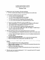
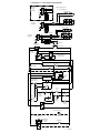
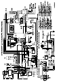
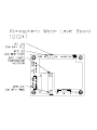
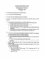
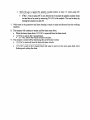
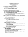
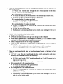
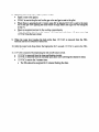
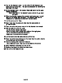
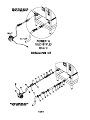
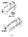
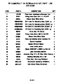
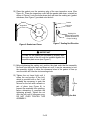
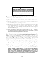
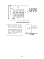
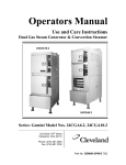
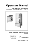
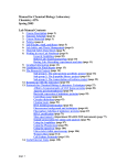
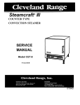
1
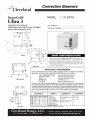
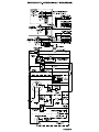
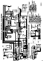
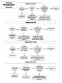
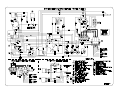
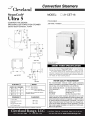
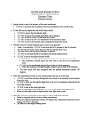
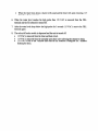
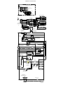
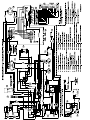
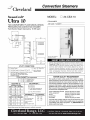
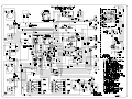
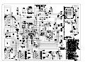
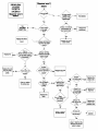
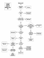
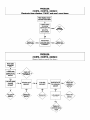
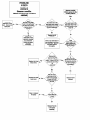
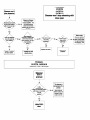
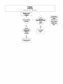
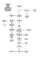
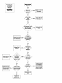
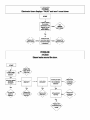
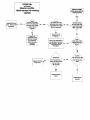
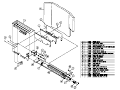
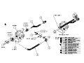
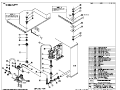
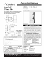
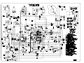
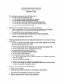
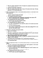
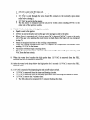
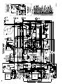
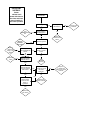
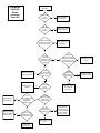
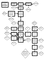
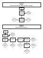
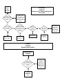
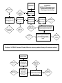
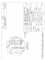
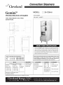
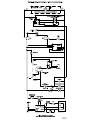
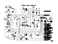
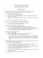
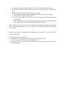
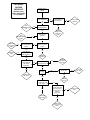
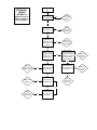
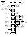
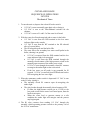
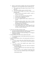
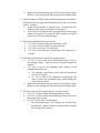
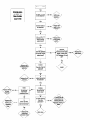
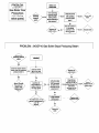
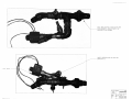
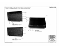
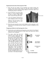
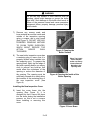
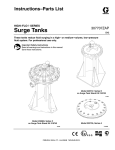
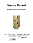
Descaling Procedure-SteamCraft Ultra and Gemini Series How Much DISSOLVE to Use Model Dissolve Ultra 3 1/2 Gallon Ultra 5 1 Gallon Ultra 10 (Elec.) 1 Gallon (ea.) Ultra 10 (Gas) 1½ Gallon Gemini 6 & 10 1 Gallon (ea.) 6. Let the descaler soak in generator for approximately one hour: 7. After one hour, turn the unit power Off: This will drain and rinse the generator for about 3 minutes. 1. Turn the unit OFF and open the doors: This will drain and rinse the generator for about 3 minutes. 2. Turn the unit power back On: The generator will begin to refill with water. 3. Select Timed with the Timed/Manual switch: DO NOT start the timer, since you do not want to heat the water during descaling. Leave the doors open. 4. Remove descaling port cap and add with the specified amount of DISSLOVE: (See chart above) Do this while the unit is refilling. The generators can take-up to 8 minutes to refill. 5. After refill has stopped, add extra tap water into the descaling port until liquid is seen entering the cooking cabinet. Note: Ultra 10 gas will have liquid coming out of the drain, Adding extra water when descaling will raise the descaling solution higher than the normal fill level, allowing the DISSOLVE to work on sensors and surfaces above the water line Note: Some SteamCraft Ultra models (the electric powered Ultra 10 and Gemini 6 and 10, for example) have two generators and two descaling ports. Both units should be descaled at the same time, using this procedure 8. After the 3-minute drain cycle completes, turn the unit back ON. After the filling has stopped, add water until liquid enters the cooking compartment (or drain for the ultra 10 gas), and then turn the unit OFF. This will drain and flush any residue from the water level control assembly. Replace descaling cap. 9. After the 3 minute drain cycle completes, Turn the unit ON and set the Timer for 20 minutes: Make sure the Time/Manual switch is in the timed setting and the doors are closed. 10. When the timer times out (after 20 minutes) turn the power Off: This will drain and rinse the generator for about 3 minutes. This ends the descaling procedure. You can now turn the unit back on and resume normal startup and cooking operations. Cleveland Range, LLC Ph: 1-216-481-4900 Fx: 1-216-481-3782 1333 East 179th St., Cleveland, Ohio, U.S.A. 44110 Visit our Web Site at www.clevelandrange.com STEAMCRAFT 3.1 ELECTRONIC TIMER (PROBE) CUSTOMER CONNECTION 380/415V L1 FIELD CONVERSION FROM 3• 3Ø L2 TO 1• IS NOT PERMITTED W/ NEUTRAL L3 DRYING ELEMENT N FU FU TB HEATING ELEMENTS CONTACTOR L1 CUSTOMER CONNECTION 1• L2 FU FU DRYING ELEMENT TB CONTACTOR L1 CUSTOMER CONNECTION L2 3• L3 HEATING ELEMENTS TB FU FU H4 RESET CIRCUIT BREAKER H1 PRIMARY X2 SECONDARY X1 120V BLK DESCALE TIMER L 3 2 4 1 78 A NO 6 5 WHT L NO DESCALE INDICATOR & RESET SWITCH 3 2 FILL VALVE 1 POWER SWITCH POWER ON 3 MIN TIMER R HEAT FILL H N TRANSFORMER 24 VAC COMPARTMENT THERMAL SWITCH WATER BOARD TO PROBES XL HI C ELECTRONIC TIMER FU COIL R1 ( OPT ) DOOR SWITCH ( SCS OPT ) MAGNETIC TIMED CONTACTOR R1 NO MANUAL C HI LIMIT SWITCH CONDENSER VALVE 1 2 HEAT STANDBY TIMER 3 ( STACKED UNITS OPTION ) COOLING FAN BLOWDOWN OPTION R1 C NC 1 INTERMITTENT BLOWDOWN TIMER DRAIN VALVE 2 3 L106346 M Cleveland Range, LLC Ph: 1-216-481-4900 Fx: 1-216-481-3782 1333 East 179th St., Cleveland, Ohio, U.S.A. 44110 Visit our Web Site at www.clevelandrange.com Cleveland Range, LLC Ph: 1-216-481-4900 Fx: 1-216-481-3782 1333 East 179th St., Cleveland, Ohio, U.S.A. 44110 Visit our Web Site at www.clevelandrange.com STEAMCRAFT 5.1 MECHANICAL TIMER CUSTOMER CONNECTION 380/415V 3Ø W / NEUTRAL TB L1 TO L2 CONTACTORS L3 N FUSEBLOCK TO H1 FU FU TO H4 HEATING ELEMENTS CONTACTORS TB L1 L2 L3 CUSTOMER CONNECTION 3• FUSEBLOCK DRYING ELEMENT TB FU FU H4 H1 PRIMARY X1 X2 SECONDARY TRANSFORMER RESET CIRCUIT BREAKER BLK WHT 120V DESCALE TIMER L 3 2 4 1 78 L A NO 6 5 DESCALE INDICATOR & RESET SWITCH NO 3 2 FILL VALVE 1 POWER ON 3 MIN TIMER POWER SWITCH R HEAT FILL H N WATER BOARD XL HI C TO PROBES TIMER T3 3 L1 T1 2 1 3 SEC TIMER DOOR SWITCH ( SCS OPT ) BUZZER COIL R1 ( OPT ) TIMED MAGNETIC CONTACTOR MANUAL THERMAL SWITCH ( HEAT STANDBY ) CONTACTOR HI LIMIT SWITCHES CONDENSER VALVE INTERMITTENT BLOWDOWN OPTION R1 C BLOWDOWN TIMER NC DRAIN VALVE 1 2 3 L106380 F STEAMCRAFT 5.1 ELECTRONIC TIMER CUSTOMER CONNECTION 380/415V 3Ø W / NEUTRAL TB L1 TO L2 CONTACTORS L3 N FUSEBLOCK TO H1 FU FU TO H4 HEATING ELEMENTS CONTACTORS TB L1 L2 L3 CUSTOMER CONNECTION 3 FUSEBLOCK DRYING ELEMENT TB FU FU H4 H1 PRIMARY TRANSFORMER RESET CIRCUIT BREAKER X2 SECONDARY X1 BLK WHT 120V DESCALE TIMER L 3 2 4 1 78 L A NO 6 5 DESCALE INDICATOR & RESET SWITCH NO 3 2 FILL VALVE 1 3 MIN TIMER POWER ON POWER SWITCH R HEAT FILL H N TRANSFORMER 24 VAC COMPARTMENT THERMOSTAT WATER BOARD XL HI C TO PROBES TIMER ( ELECTRONIC ) FU COIL R1 ( OPT ) CONTACTOR DOOR SWITCH ( SCS OPT ) MAGNETIC TIMED CONTACTOR HI LIMIT SWITCH HI LIMIT SWITCH MANUAL CONDENSER VALVE THERMAL SWITCH ( HEAT STANDBY ) INTERMITTENT BLOWDOWN OPTION R1 BLOWDOWN TIMER C NC 2 1 DRAIN VALVE 3 L106379 F Cleveland Range, LLC Ph: 1-216-481-4900 Fx: 1-216-481-3782 1333 East 179th St., Cleveland, Ohio, U.S.A. 44110 Visit our Web Site at www.clevelandrange.com Cleveland Range, LLC Ph: 1-216-481-4900 Fx: 1-216-481-3782 1333 East 179th St., Cleveland, Ohio, U.S.A. 44110 Visit our Web Site at www.clevelandrange.com Cleveland Range, LLC Ph: 1-216-481-4900 Fx: 1-216-481-3782 1333 East 179th St., Cleveland, Ohio, U.S.A. 44110 Visit our Web Site at www.clevelandrange.com PROBLEM: 24CGA10 Steam cabinet won't steam with time on the timer and time/ manual switch in the timed position Steam cabinet won't steam Is the red light on? No Is there power to the steamer? No Yes See Steamer won't fill. No Is there water in the sight glass? Yes Yes See Steamer generator won't ignite Replace the on/off rocker switch Has the steam generator ignited? No Yes Repair or replace the wiring to the switch No Is there power to the Timed/Manual switch? No Yes Replace the switch No Yes Is there power from the Timed/ Manual switch? Replace the timer Yes Does the steamer have the optional door switch? No Yes Replace the door switch Is there 120 VAC accross the coil of the steam solenoid.? Yes Yes Does the steam cabinet steam when the door switch is bypassed? Does the steamer steam in manual mode? No Replace the steam solenoid No Repair or replace the wiring to the steam solenoid Connect power to steamer. Steam generator won't fill. PROBLEM: 24CGA10 Steam generator won't fill Yes Is there power to the steamer? No Supply power to the steamer. No Supply cold water to the steamer. Yes Is there water to the steamer? Yes Is there 120 VAC between the H and N on the water board? No Replace the on/off rocker switch . Yes Is there 120 VAC between Fill and N on the water board? No Remove the wire from the HI terminal on the water board. Is there 120 VAC between Fill and N? No Replace the water board Yes Yes Replace the wiring to the fill solenoid. No Is there 120 VAC across the coil of the fill solenoid? No Yes Is water leaving the fill solenoid? Is there debris on the HI probe in the probe assy? Yes Replace the fill solenoid Clean the probes or replace the probe assy. Yes Replace wiring to drain solenoid. No Does the steamer have the optional intermittent blowdown timer? No Is there 120 VAC across the coil of the drain valve? Yes Yes Replace the wiring to the intermittent blowdown timer . No Is there 120 VAC between terminals 2&3 on the timer? Yes Replace the intermittent blowdown timer. Is water draining from the generator? Yes Replace the drain valve. No If water is leaving the fill solenoid and not draining from the generator where is it going? check for leaks.. No Replace the wire to the Hi probe. PROBLEM: 24CGA10 Steam generator won't ignite Is the red light on? Steam generator won't ignite No No Connect power to the steamer Yes Yes See Steamer won't fill No Is there water in the sight glass? Replace the on/off switch Yes Clean or replace the probe assy. Is there power to the steamer? Is there 120 VAC between Heat and N terminals on the water No level board with a jumper between terminal XL and C? Is there 120 VAC between the terminals Heat and N on the water level board with the the low probe submerged? No Yes Yes Replace water level board. Replace the igniton module. Replace the Timed/Manual switch. No Is there 120 VAC to the coil of cabinet relay R1? No No Adjust or replace the air prover switch. Yes No With the Top cabinet in the No manual position, is there 120 VAC to the fan? Yes Replace the cabinet relay (R1or R2). Is there 24 VAC on ignition transformer? No Yes With the bottom cabinet in the manual position, is Yes there 120 VAC to the fan? Is there 24 VAC to the R4 coil? Yes With the high limit temporarily by passed is there 24 Yes VAC to the ignition module? Replace the fan. Replace the high limit. No Does the fan turn? Yes Is there 24 VAC to the gas valve? Yes No Replace the R4 relay. No Yes Is there 24 VAC to the R3 coil? Yes Is there 120 VAC to the cabinet relay R2 coil? No Is there 24 VAC to the PV and MV/PV terminals on the No Gas valve and spark to the igniter for 90 seconds? Replace the timed/manual switch. Replace the R3 relay Replace the ignition module Yes Is the pilot valve opening? No Replace the gas valve. No Supply gas to the steamer Yes Due to the construction of the burner box it is best to replace the ignitor, ignition cable and sensor (ground wire ) at the same time. Yes Is there gas to the steamer? PROBLEM: 24CGA10 Electronic timer displays "PAUS" and won't count down START Is steam heating the cooking cabinetabove 192 degrees (the set temp of the thermo-switch)? No See Steamer won't steam No Replace the electronic timer Yes Replace the thermo-switch Yes Does the timer count down when the thermo-switch is bypassed? PROBLEM: 24CGA10 Steam leaks around the door. START Is COLD water supplied to the steamer? No Supply cold water (35-60 PSI) to the steamer. Yes Is the door gasket physically damaged? Yes Turn over the gasket or replace it. No Is the door out of alignment? No Is the drain obstructed? No Is there 120 VAC across the coil of the condensate solenoid? Yes Yes Yes Replace the door bearings and pins. Remove the obstruction Is the solenoid opening? Yes Replace the condensate spray nozzle No Replace the wiring to the condensate solenoid. No Replace the condensate solenoid. Steamer won't stop steaming Is the timed/manual switch in the timed position with no time on the timer? PROBLEM: 24CGA10 Steamer won't stop steaming with door open No Steamer will steam constantly in the manual position. Put the timed/manual switch in the timed position with no time on the timer. Yes Does the steamer have the optional door switch? No Does steamer continue to steam with both wires removed from terminal 1 on the heat standby timer? No Is there 120 VAC to the coil of the contacter? Yes No Is there an amp draw at the element? Yes Yes Yes Replace the timer. Adjust or replace the door switch. Replace the heat standby timer. Replace the contactor Problem: 24CGA10 Steamer won't preheat Steamer won't preheat Is the timed/manual switch in the timed postion with time on it or in the manual postion? Yes See Problem: steamer won't steam. No This steamer is not equiped with a preheat thermostat. The timed manual switch must be in manual or time must be on the timer. No When power is removed from the element steam is still made for approximately 10 seconds. This is normal. Generator overpressurizes PROBLEM: 24CGA10 Generator over-pressurizes (relief valve discharges constantly) Replace spray nozzle See Problem: Steamer Floods No Yes Is discharge from relief valve cold? No Is the condensate spray nozzle spraying a cone of cold water down the drain? Yes Is condensate solenoid operating properly? Yes No Does generator over-pressurize with door open (and optional door switch bypassed)? Yes Is gas pressure correct (Natural: 2.0" Low and 3.5" high. L.P.: 4.2" low, 10" high)? Adjust or replace the gas valve Yes No Check drain for any obstructions and correct installation. No Replace the normally open relief solenoid Replace condensate solenoid. Yes Does the generator over-pressurize only when both cabinets have been running and are then shut down? No Descale generator Yes Does generator over-pressurize when the steam supply hoses have been disconnected from the steam manifolds? Warning: Steam is hot!! No Replace the steam solenoids Problem: 24CGA10 Steamer Floods (Water is entering cabinet through the steam nozzles) Steamer Floods Replace the fill solenoid. No Is 120 VAC to the fill solenoid with water touching the top probe? Replace the water level board. Yes Replace the 3 minute timer. No Is there 120 VAC to the fill solenoid with the wire removed from terminal 1 on the 3 min. timer? Yes Yes Is there 120 VAC to the fill solenoid with a jumper placed from the HI terminal to the C terminal on the water level board? No Clean or replace the probe housing Cleveland Range, LLC Ph: 1-216-481-4900 Fx: 1-216-481-3782 1333 East 179th St., Cleveland, Ohio, U.S.A. 44110 Visit our Web Site at www.clevelandrange.com SteamCraft Gemini 10 ® TM MODEL: 24-CGA-10.2 TWO COMPARTMENT FLOOR MODEL DESIGN PRESSURELESS CONVECTION STEAMER TWIN, INDEPENDENT GAS-FIRED GENERATORS Cleveland Standard Features ■ Cooking Capacity for up to ten 12˝ x 20˝ x 2 1/2˝ deep ITEM NUMBER __________________________________________ JOB NAME / NUMBER __________________________________ Cafeteria Pans, five each compartment. ■ Totally independent cooking compartments, each has its' own generator, gas valve and water level controls - no shared components ■ Exclusive High Efficiency Gas Power Burner (forced air) Generator: Produces more steam for faster cooking while lowering operating costs (72M BTU's per compartment) ■ Easy Access Cleaning Port: Each generator has a deliming port located on the outside, top of the unit ■ Generator Cleaning Light for each compartment warns the operator to delime generator ■ Instant Steam Standby Mode: Holds generator at a steaming temperature, allows unit to start cooking instantly ■ Each compartment has one, 60-Minute Electro-Mechanical Timer with load compensating feature. Manual Bypass Switch for constant steaming. ■ Durable 14 Gauge, 304 Stainless Steel construction for compartment door, cooking cavity and steam generator ■ Exclusive Two-Piece Compartment door: Slammable, self-adjusting door provides and airtight seal, reversable door gasket for extended life ■ Exclusive Gemini Drain/Power Control System: Simple, reliable 1/2" ball valve style drain automatically turns power ON/OFF Short Form Specifications Shall be Two Compartments, Cleveland Convection Steamer series SteamCraft Gemini 10, Model 24-CGA-10.2, Twin Gas Atmospheric Steam Generator, 72M BTU"s input per compartment. Independent steam generator, gas valve and water level control system. Automatic Generator Blowdown. Steam Generator with Automatic Water Fill on start up. Exclusive remote probe-type water level controls. Exclusive Brass “Steam Jet” distribution system. Two-piece freefloating compartment door. Type 430 Stainless Steel exterior and cooking compartments. Pullout service drawer for controls and Gemini Drain/Power Control System. Exclusive Cold Water Condenser design. Choice of Compartment Controls. Manual TM ■ Exclusive Brass Steam Jets distribute even-high velocity steam throughout cooking compartment for faster cooking times ■ Easy, Front -Access Generator Controls comes with a pullout drawer for simple servicing of unit ■ 6˝ Stainless Steel Adjustable Legs with Flanged Feet ■ Approvals: CSA (AGA, CSA) and U.L/NSF#4 ■ Compartment Steam Shut-Off Switch (SCS) ❐ Propane Gas (PG) Options & Accessories ❐ Electronic Timer with Compensating Feature (ETC) ❐ On/Off Steam Switch Controls, no timer (MC) ❐ Dissolve ® Descale Solution, 6 one gallon container w/quart markings (106174) ❐ Water Filters SECT. Cleveland Range Inc. IV 13 PAGE 0402 1333 East 179th St., Cleveland, Ohio, U.S.A. 44110 Ph: 1-216-481-4900 Fx: 1-216-481-3782 Visit our Web Site at www.clevelandrange.com Each Compartment has capacity for: • Five, 12˝ x 20˝ x 21⁄2˝ deep Cafeteria Pans. WATER QUALITY REQUIREMENTS The quality of water varies greatly from region to region. Steam equipment generators must be drained daily and chemically descaled periodically to ensure proper operation. To minimize service problems caused by the accumulation of minerals and chemicals in water review the following quality guidelines with a local water treatment specialist. Inlet water that is beyond these specified guidelines should be treated to achieve these acceptable limits. Total Dissolved Solids less than 60 ppm, Alkalinity less than 20 ppm, Silica less than 13 ppm, pH factor greater than 7.5, Chlorine less than 30 ppm. A DE B GAS ELECTRIC 11⁄4 ˝ IPS line size, 3⁄4˝ (13mm) connection 120V-1Phase, 60 Hz. 35 psi minimum 60 psi maximum NATURAL PROPANE BTU 2 Blowers & Controls Piping 3⁄4˝ N.P.T. Piping 3⁄4˝ N.P.T. 72,000 each 150 watts each C COLD WATER Supply pressure Supply pressure Generator, One (E) 1/4" dia. 4.50˝ W.C. Min. 11.00˝ W.C. Min. 144,000 total NPT for Generator 14.00˝ W.C. Max. 14.00˝ W.C. Max. One (D) 1/4" dia Manufacturer must be notified if unit will be used above 2,000 feet NPT for Condenser C CLEARANCE Right - RIGHT 3”, Left - 3”, = Rear -3” D DRAINAGE 3˝ operating, 11⁄2˝ dia. 12˝ if adjoining wall or (12” on control side if adjoining wall or equipment LEFT =is over 3˝ 30” high for service access) Do not connect other units to this drain REAR = 3˝ Allow 6˝ space min. Drain must be vented when located near Do not use PVC pipe Contact factory for variances to and sides from rear clearances. combustible walls NOTES: Cleveland Range reserves right of design improvement or modification, as warranted. Many regional, state and local codes exist and it is the responsibility of the owner and installer to comply with the codes. Cleveland Range equipment is built to comply with applicable standards for manufacturers. Included among those approval agencies are UL/NSF#4 and CSA (AGA, CGA). (NOT TO SCALE) SECT. PAGE 0402 Litho in U.S.A. IV 14 CLEVELAND RANGE 24CGA10.2 SEQUENCE OF OPERATIONS Mechanical Timer Starting with the timed manual switch in the timed position, and no time on the timer. 1. To turn the unit on, turn the ON/OFF lever clockwise to the ON position • This mechanically closes the drain. • The red “Power On” indicator is energized. • 115 VAC is sent through the timer to the three-second timer, which activates the buzzer for three seconds. • 115 VAC is sent through the normally closed R1 contacts to the fan motor, turning it ON • 115 VAC is sent to H and N of the water level board 2. With the water level board energized and no water in the generator • 115 VAC is sent from the FILL terminal to the fill solenoid. • The fill solenoid opens and the generator fills. 3. The water fills to the low probe shorting it to ground • 115 VAC is sent from the HEAT terminal to the timed manual switch. • 115 VAC is sent through the high limit to the primary of the 24VAC transformer. • The water continues to fill until the water level reaches the high probe then 115 VAC is removed from the FILL terminal and the fill solenoid is turned off 4. 24VAC is sent to the ignition module. • Spark is sent to the igniter. • 24VAC is sent to the pilot coil of the gas valve and the coil of the R1 relay. • The normally closed R1 contacts open, turning off the fan • The pilot lights, which acts as a standby heater. When the pilot is ignited and the module detects 1.0 micro amps DC, the MV terminal on the module is energized it remains in this standby heat mode until a cooking compartment is turned “ON” (see step 5). 5. When the timed/manual switch is in the timed position and time is on the timer or the timed manual switch is set to the manual position: • 115 VAC is sent to the clean light timer. • When the clean light timer times down 115 VAC is sent to the clean light switch. • When the clean light switch is depressed the timer is reset. • 115 VAC is sent from the compartment timer through the door switch to the normally closed contacts of the compartment thermostat and R2 relay coil. • The “Sure Cook” light is energized. • 115 VAC is also sent from the door switch through the now closed contacts of the R1 relay to the fan motor. • The fan motor turns ON, and comes up to speed. • • • The fan prover switch makes allowing 24 VAC to the normally open R2 contacts. The normally open R2 contacts close and 24 VAC is sent to the main coil of the gas valve. The main burner is ignited and the water heated to steam. • Steam enters the cabinet and the compartment thermostat closes at 193 degrees. • The “Sure Cook” light is de-energized. • If in the timed mode, 115 VAC is sent to the timer motor and the timer begins counting down. • The condensate solenoid is energized sending cold water down condensate spray nozzle pulling the steam around the product and down the drain. 6. When the timer times out or the unit is switched to the timed mode (with no time on the timer) from the manual mode, 115 VAC is sent to the 3 second timer and then to the buzzer for 3 seconds. 7. Whenever the water level drops below the high probe for 5 seconds 115 VAC is sent to the FILL terminal again. 8. When the on/off lever is turned off : • The drain is mechanically opened, and the generator begins to drain. • The red “Power On” indicator light is de-energized. • 115 VAC is sent to the 3-minute timer and the fill solenoid is energized for 3 minutes flushing the drain. PROBLEM: 24CGA6 24CGA10.2 Steamer won't steam Steamer won't steam with handle in on position Is the red light on? Is there power to the steamer? No No Connect power to steamer. Yes See Steamer won't fill. See Steamer won't ignite No Is there water in the sight glass? Yes Yes Adjust or replace the on/off micro switch Has the pilot ignited? No Yes Replace the wiring to the switch No Is there power to the Timed/Manual switch? No Yes Replace the switch No Yes Is there power from the Timed/ Manual switch? Replace the timer Yes Does the steamer steam with the door switch bypassed? Does the steamer steam in manual mode? No Is there 120 VAC to the R2 relay? Replace the wiring to relay No Yes Yes Is the fan turning? Replace the door switch Is there 120 VAC to the fan? No No Check the R1 relay Yes Yes Is there 24 VAC to the main coil of the gas valve? Yes Replace the gas valve? Replace the fan No Does the coil to the main gas valve get 24 VAC when the fan prover switch is bypassed? Yes Replace the the fan prover switch. No Replace the R2 relay. Steamer won't fill PROBLEM: 24CGA6 24CGA10.2 Is there power to the steamer? Steamer won't fill with the handle in the on position No Connect power to the steamer No Supply water to the steamer. No Adjust or replace on/off micro switch Yes Is there water to the steamer? Yes Is there 120 VAC between the terminals H and N on the watr level board? Yes Is there 120 VAC between terminals Fill and N on the water board? Adjust or replace the on/ off micro switch Replace the fill solenoid. No No Yes Yes Is there 120 VAC across the coil of the fill solenoid? Is there debris on the HI probe in the probe assy? Yes Yes Is water leaving the fill solenoid? Clean or replace the probe assy. Yes Clean or replace the drain valve. No No With the wire removed from the HI terminal on the water No level board, is there 120 VAC between terminals Fill and N? Does the manual drain valve close completely? Yes No Replace the water level board. Replace the wire to the HI probe. PROBLEM: 24CGA6 24CGA10.2 Steam generator won't ignite Is the red light on? Steamer won't ignite No No No Connect power to the steamer No Replace the gas valve. Yes Yes See Steamer won't fill Is there power to the steamer? Adjust or replace the on/off micro switch Is there water in the sight glass? Yes Clean or replace the probe assy. No Is there 120 VAC between Heat and N terminals on the water level board with a jumper between terminal XL and C? No Yes Is there 120 VAC between the terminals Heat and N on the water level board with the the low probe submerged? yes Is there 120 VAC across the primary of the 24 VAC ignition transformer? Replace water level board. No Does the pilot gas valve open when the 24 VAC is applied? Yes Replace the transformer No Replace the high limit Is there 24 VAC to the secondary of the ignition transformer? Yes Is spark generated at the igniter? Yes No Replace the igniter and wire Yes Replace the wires to the ignition module. No Is there 24 VAC to the ignition module? Is there at least 1.0 micro amps DC at the burner ground terminal on the ignition module? Yes Replace the ignition module No Is there spark from the module until the 90-second lock out? Yes Yes Replace the ignition module Yes Is there 24 VAC to the pilot coil on the gas valve until the 90-second lock out? No Yes Supply gas to the steamer No Does the steamer have gas supplied? No Is the pilot flame blue and No enveloping the igniter? Yes Replace the ground wire Replace the pilot assy PROBLEM: 24CGA6, 24CGA10.2 Electronic timer displays "PAUS" and won't count down START Is steam heating the cooking cabinetabove 192 degrees (the set temp of the thermo-switch)? No See Steamer won't steam No Replace the electronic timer Yes Replace the thermo-switch Yes Does the timer count down when the thermo-switch is bypassed? PROBLEM: 24CGA6, 24CGA10.2 Steam leaks around the door. START Is COLD water supplied to the steamer? No Supply cold water (35-60 PSI) to the steamer. Yes Is the door gasket physically damaged? Yes Turn over the gasket or replace it. No Is the door out of alignment? No Is the drain obstructed? No Is there 120 VAC across the coil of the condensate solenoid? Yes Yes Yes Replace the door bearings and pins. Remove the obstruction Is the solenoid opening? Yes Replace the condensate spray nozzle No Replace the wiring to the condensate solenoid. No Replace the condensate solenoid. Cleveland Range, LLC Ph: 1-216-481-4900 Fx: 1-216-481-3782 1333 East 179th St., Cleveland, Ohio, U.S.A. 44110 Visit our Web Site at www.clevelandrange.com CLEVELAND RANGE SEQUENCE OF OPERATIONS 24CGP10 Mechanical Timer 1. To turn the unit on, depress the red on/off rocker switch. • 115 VAC is sent to normally open drain valve closing it. • 115 VAC is sent to the Timed/Manual switches for the cabinets. • 115 VAC is sent to L1 and L2 of the water level board. 2. With the water level board energized and no water in the boiler • 115 VAC is sent from the IND terminal to the low water indicator light on the console. • 115 VAC is sent from the WF terminal to the fill solenoid after a 5-second delay. • The fill solenoid opens and the boiler fills. • The water fills to the secondary low water cutoff probe in the boiler, shorting it to ground • 115 VAC is removed from the IND terminal and the low water indicator light is de-energized. • 115 VAC is sent from the HTR terminal through the normally closed contact of the high-pressure switch to the normally open contacts of the amber reset switch, • 115 VAC is sent through the normally closed R1 contacts to energize the amber light on the reset switch. • If the low water cut off probe is not grounded for 20 seconds, 115 VAC is removed from HTR and sent back to IND energizing the low water light. 3. When the momentary amber switch is depressed 115 VAC is sent to the R1 relay closing it. • The normally closed R1 contacts open de-energizing the amber light. • The relay latches through the normally closed contacts of R1 • If either the high-pressure switch (set at 15 PSI) or the low probe circuit on the water level board opens, then the latch circuit opens. • When the water level or pressure returns to a safe condition the amber light will energize and the process may begin again. 4. The R1 relay contacts close sending 115 VAC through the normally closed operating pressure switch to the primary coil of the 24 VAC transformer. • 24VAC is sent from the secondary of the 24 VAC transformer through the low water cutoff float switch to the R2 relay coil. • The normally open R2 contacts close and send 115 VAC to the fan. • The fan turns and the air prover switch is closed. • 24 VAC is sent through the air prover switch to the ignition module. • With 24 VAC to the ignition module a spark is generated at the igniter. • 24VAC is sent to the pilot coil on the gas valve. • The pilot valve is energized and opens. • Gas is sent to the pilot burner. • The gas is ignited and the flame rectifies the AC current. • When the ignition module reads at least 1.0 micro amps DC current through the ground wire the coil to the main gas valve is energized • The pilot flame lights the main burner. • If the module does not read 1.0 micro amps DC in 90 seconds it will shut down the main burner and make one more try before locking out. 5. The water in the boiler is heated to steam. • As steam is generated and pressure builds the air is pushed out through the steamtrap on the lower steam manifold. • Steam goes through the steam trap heating it to 192 degrees closing the steam trap. 6. Pressure builds in the boiler to the set point of 8-10 PSI. • The operating pressure switch opens and the heat circuit is de-energized. 7. With the timed/manual switch in the timed position and time on the timer. • 115 VAC is sent to the steam solenoid and steam is sent to the cooking cabinet. There the steam is directed around the product • 115 VAC is sent to the normally open contacts of the compartment thermostat. • The normally open contact close when the thermostat reaches 193 degrees. • 115 VAC is sent to the timer motor and the timer begins to count down • 115 VAC is sent to the condensate solenoid and cold water is sent to the condensate spray nozzle pulling the steam down the drain.. • When the steam pressure drops below the operating set point the heat circuit is energized and the heat process begins again. 8. Water continues to fill the boiler until the operational water float is lifted and closes, shorting the HI terminal on the water level board to the C terminal. . • When the HI terminal is shorted to the C terminal the WF terminal on the water level board is de-energized. • If the water level drops and the operational water float switch opens for more than 5 seconds the WF terminal is energized and the water fill circuit begins again. 9. When the mechanical timer counts down: • 115 VAC is removed from the condensate circuit. • 115 VAC is removed from the steam solenoid. • 115 VAC is sent to the 3-second timer • 115 VAC is sent from the 3-second timer to the buzzer for 3 seconds. 10. With the timed/manual switch in the manual position • 115 VAC is sent to the steam solenoid and steam is sent to the cooking cabinet. There the steam is directed around the product • 115 VAC is sent to the normally open contacts of the compartment thermostat. • The normally open contact close when the thermostat reaches 193 degrees. • 115 VAC is sent to the condensate solenoid and cold water is sent to the condensate spray nozzle pulling the steam down the drain.. • When the steam pressure drops below the operating set point the heat circuit is energized and the heat process begins again. 11. The unit is turned off by depressing the red rocker switch. • 115 VAC is removed from the timing and heat circuits. • 115 VAC is removed from the normally open blowdown valve allowing the unit to drain. • 115 VAC is sent to the 3-minute timer. o The three-minute timer will energize the fill and rinse solenoids for 3 minutes while the steamer drains assisting and cooling the blowdown. . CLEVELAND RANGE SEQUENCE OF OPERATIONS 24 CGP 10 Electronic Timer 1. To turn the unit on, depress the red on/off rocker switch. • 115 VAC is sent to normally open blowdown valve closing it. • 115 VAC is sent to the 24 VAC transformer to the timer. • 24 VAC is sent to the timer. • 115 VAC is sent to the Timed/Manual switches for the cabinets. • 115 VAC is sent to L1 and L2 of the water level board. 2. With the water level board energized and no water in the boiler • 115 VAC is sent from the IND terminal to the low water indicator light on the console. • 115 VAC is sent from the WF terminal to the fill solenoid after a 5-second delay. • The fill solenoid opens and the boiler fills. • The water fills to the secondary low water cutoff probe in the boiler, shorting it to ground • 115 VAC is removed from the IND terminal and the low water indicator light is de-energized. • 115 VAC is sent from the HTR terminal through the normally closed contact of the high-pressure switch to the normally open contacts of the amber reset switch, • 115 VAC is sent through the normally closed R1 contacts to energize the amber light on the reset switch. • If the low water cut off probe is not grounded for 20 seconds, 115 VAC is removed from HTR and sent back to IND energizing the low water light. 3. When the momentary amber switch is depressed 115 VAC is sent to the R1 relay closing it. • The normally closed R1 contacts open de-energizing the amber light. • The relay latches through the normally closed contacts of R1 • If either the high-pressure switch (set at 15 PSI) or the low probe circuit on the water level board opens, then the latch circuit opens. • When the water level or pressure returns to a safe condition the amber light will energize and the process may begin again. 4. The R1 relay contacts close sending 115 VAC through the normally closed operating pressure switch to the 24 VAC transformer. • 24VAC is sent through the low water cutoff float switch to the R2 relay coil. • The normally open R2 contacts close and send 115 VAC to the fan. • The fan turns and the air prover switch is closed. • 24 VAC is sent through the air prover switch to the ignition module. • With 24 VAC to the ignition module 24VAC is sent to the pilot coil on the gas valve. • A spark is generated at the igniter. • • • • • • The pilot valve is energized and opens. Gas is sent to the pilot burner. The gas is ignited and the flame rectifies the AC current. When the ignition module reads at least 1.0 micro amps DC current through the ground wire the coil to the main gas valve is energized The pilot flame lights the main burner. If the module does not read 1.0 micro amps DC in 90 seconds it will shut down the main burner and make one more try before locking out. 5. The water in the boiler is heated to steam. • As steam is generated and pressure builds the air is pushed out through the steamtrap on the lower steam manifold. • Steam goes through the steam trap heating it to 192 degrees closing the steam trap. 6. Pressure builds in the boiler to the set point of 8-10 PSI. • The operating pressure switch opens and the heat circuit is de-energized. 7. With the timed/manual switch in the timed position (with time on the timer) or in the manual position: • The timer display alternates between “PAUS” and the time set. • 115 VAC is sent to the steam solenoid and steam is sent to the cooking cabinet. There the steam is directed around the product. • When the cooking compartment reaches 193 degrees internally the thermal switch closes. • The timer begins to count down • 115 VAC is sent to the condensate solenoid. The condensate solenoid sends cold water to the condensate spray nozzle pulling the seam down the drain. • When the pressure drops below the set point the heat circuit is energized and the heat process begins again. 8. Water continues to fill until the operational water float is lifted and closes, shorting the HI terminal on the water level board to the C terminal. . • When the HI terminal is shorted to the C terminal the WF terminal on the water level board is de-energized. • If the water level drops below the operational water float switch for more than 5 seconds the WF terminal is energized and the water fill circuit begins again. 9. When the electronic timer counts down: • 115 VAC is removed from the condensate circuit. • 115 VAC is removed from the steam solenoid 10. With the timed/manual switch in the manual position • 115 VAC is sent to the steam solenoid and steam is sent to the cooking cabinet. There the steam is directed around the product • 115 VAC is sent to the normally open contacts of the compartment thermostat. • • The normally open contact close when the thermostat reaches 193 degrees. • 115 VAC is sent to the condensate solenoid and cold water is sent to the condensate spray nozzle pulling the steam down the drain.. When the steam pressure drops below the operating set point the heat circuit is energized and the heat process begins again. 11. The unit is turned off by depressing the red rocker switch. • 115 VAC is removed from the timing and heat circuits. • 115 VAC is removed from the normally open blowdown valve allowing the unit to drain. • 115 VAC is sent to the 3-minute timer. • The three-minute timer will energize the fill and rinse solenoids for 3 minutes while the steamer drains assisting and cooling the blowdown. . 1333 East 179th Street Cleveland, Ohio 44110 Phone: (216) 481- 4900 Fax: (216) 481- 3782 Installation Instructions For P/N 110329 Replacement Boiler Inspection Cover Assembly for the Power 10 1 – Cover Brace 2 – Inspection Cover Parts List Replacement P-10 Boiler Inspection Cover 1 – P/N 110316 Cover Brace 2 – P/N 110315 Inspection Cover 3 – P/N 110248 Gasket 4 – P/N 110330 Sealing Nut Sealing Side 3 – Gasket 4 – Sealing Nut (Shown enlarged) 1333 East 179th Street Cleveland, Ohio 44110 Phone: (216) 481-4900 Fax: (216) 481 3782 Part No. 260AVG – A 5/01 Replacement Instructions Rear Inspection Plate. 1) Start with the unit turned off and completely cool. Before starting this process, verify that the Power switch is in the OFF position, the boiler is completely cool and the pressure gauge adjacent to the power switch is not showing any pressure in the boiler. 2) Remove the Rear Cover Panel (See Figure 1). If the unit being worked on does not have a Rear Cover Panel, remove the rear panel itself. 3) If the unit is already equipped with a boiler inspection cover of the type shown on the front cover of this instruction, remove the old cover and go directly to Step 7. Rear Cover Panel Figure 1 Rear Cover Panel 4) Before the new inspection cover can be installed it will be necessary to first remove the old cover plate and then “prepare” the boiler for installation of the new cover. Preparing the Boiler for the New Inspection Cover 5) Remove the six nuts holding the old inspection cover in place (do not discard these nuts as they will be needed in a later step). Next remove the existing inspection cover and gasket. 6) The studs, which held the old inspection cover in place, will need to be removed (shortened). The best way to shorten these studs is to place the nuts (removed in Step 5) onto the exposed stud (see Figure 2). Tighten the nut down onto to the stud with a wrench or socket until it threads flush with the weld base of the stud. Continue to tighten the nut until the stud breaks. Providing the remaining stud is not higher than ¼ inch, no additional conditioning of the stud base is necessary. If the remaining base of the stud is still higher than a ¼ inch, file down its height until the top is no more than a ¼ inch above the plate. 1 of 5 Reinstall Nut on Stud Nut Threaded Down to Base Final Shortened Stud ¼ inch Max Figure 2 Stud Removal WARNING Do not use any method of stud removal such as grinding, which might damage or gouge the boiler face itself. Such damage to the boiler could result in failure of the pressure vessel and cause premature equipment failure, property damage, personal injury and/or death. 7) Remove any excess scale and loose material around the inside and outside of the inspection opening using a scraper and a wire brush (See Figure 3). DO NOT USE ANY POWERED GRINDING METHOD TO CLEAN THESE SURFACES, WHICH MIGHT REDUCE THE ACTUAL BOILER WALL THICKNESS. 8) The new boiler inspection cover has a centering plug to insure that it is properly located when installed into the inspection port. To prepare the opening itself, lightly tap the edge of the boiler opening and/or use emery cloth to remove any build-up that would effect the roundness of the opening or reduce the diameter of the opening. The opening must be sufficiently cleared as to easily allow the insertion of the centering plug of the new inspection cover. (see Figure 4) Figure 3 Cleaning the Boiler Surface Either Tap Lightly with a Hammer and/or use Emery Cloth to Remove Build-Up in the Opening Itself Figure 4 Cleaning the Inside of the Boiler Opening Installing the New Inspection Cover 9) Insert the cover brace into the opening (See Figure 5). It is designed so that it cannot fall down into the boiler during the installation process, so this is not a concern when installing or removing this cover. Figure 5 Cover Brace 2 of 5 10) Place the gasket over the centering plug of the new inspection cover (See Figure 6). Place the inspection cover with the gasket side down, oriented as shown in Figure 6, onto the boiler brace bolt and start the sealing nut (gasket side down, see Figure 7) provided onto the bolt. Gasket Gasket Inspection Cover Inspection Cover Sealing Nut (Nylon Edge Installed Towards the Boiler for Proper Sealing) Figure 7 Sealing Nut Direction Figure 6 Gasket and Cover IMPORTANT In order for the sealing nut provided to properly seal, the nylon side of the nut must be installed against the inspection plate cover (see Figure 7). 11) Before tightening the sealing nut, position the plate such that the assembly fits flush onto the boiler face and does not rock. It may be necessary to turn the assembly slightly to allow the clearance holes in the gasket to line up over the stubs left from the old mounting studs. 12) Tighten the nut hand tight until it clears the end portion of the bolt, which is provided with a flat. It will probably be necessary to grab the flat end on the bolt with a wrench or pair of pliers (see Figure 8), to prevent the assembly from spinning, before attempting to complete the tightening process. Tighten the nut onto the bolt until it becomes snug. DO NOT OVER TIGHTEN THIS ASSEMBLY. 3 of 5 Tighten Figure 8 Tightening the Nut WARNING Do not over tighten the sealing nut. Over tightening can damage the boiler head and the brace assembly, which may prevent the assembly from sealing and/or cause premature equipment failure, property damage, personal injury and death. Test procedure (See the operating label found on the unit for additional details of the start-up procedure for the boiler) 13) Turn on the main power switch to the boiler, which will fill the unit with water. 14) Turn the individual control compartments to the timed (with the timers zeroed) or OFF position, depending on model. 15) Once the unit is filled with water, press the amber-lighted steam switch. The boiler will light and come up to pressure. When the burners turn off, the boiler should now be at operating pressure (the steam pressure gauge should read about 12 psi). 16) Check the inspection opening for any signs of leaks. If a leak is observed, put a wrench onto the nut (holding the flat of the bolt if necessary to prevent the assembly from spinning) and turn the nut tighter. Note: If the nut bottoms out, and the assembly continues to leak even after the nut seems completely tight, DO NOT CONTINUE TO TIGHTEN. Turn OFF the main power switch, and allow the unit to cool. Remove the nut, and put a bead of high temperature silicone around the threads at the sealing surface. Reinstall the nut as shown in Figure 7. Repeat Steps 12 – 16. 17) Once the seal of the new inspection plate has been checked, turn off the power to the unit and allow the unit to cool. If the original steamer had an opening in the rear panel for inspection plate access, go to Step 19, otherwise it will be necessary to cut a clearance opening in the rear sheeting. 18) If your steamer does not currently have an inspection opening in the rear panel it will be necessary to fashion a clearance opening in this panel to clear the mounting bolt of the new rear inspection cover for the boiler. Cut at least a 2” diameter or larger opening 11 ⅛ in from the top of the rear panel centered in the middle using a Greenlee knockout punch or similar method (See Figure 9 on the following page). Alternatively, a rectangular cutout as shown in Figure 9 in dotted lines can also be used. Be sure to remove any burrs or sharp edges left in the new opening from the cutting operation. 4 of 5 11.125 As an alternate, a rectangular opening can be cut out to remove the four louvers shown 11.875 Figure 9 Rear Panel Modification 19) Reinstall any panels that were removed to install the new boiler inspection cover. If your steamer had a rear cover panel installed on the rear sheeting, this can either be left off the unit once the new boiler cover is installed or modified by installing a clearance hole to clear the bolt. See Figure 10. 20) The Steamer is now ready for operation. 5 of 5 Cut a 2” Diameter Hole or Similar Opening Centered on the Plate Figure 10 Modifying the Rear Cover Panel Cleveland Range, LLC Ph: 1-216-481-4900 Fx: 1-216-481-3782 1333 East 179th St., Cleveland, Ohio, U.S.A. 44110 Visit our Web Site at www.clevelandrange.com