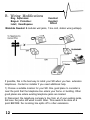
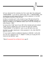
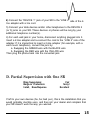
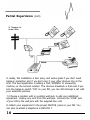
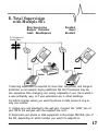
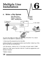
1
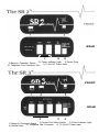
SR Series
Selective Ring Processor
Online Operating
Instructions
www.multi-link.net
REAR
.
/
3
4
5
3) Device Ports
2) Power Indicator Light
1) Barge-In Protection Switch
5) 12 Volt AC Power Input
4) Telephone Line Connector Port
FRONT
REAR
4
5
6
3) Power Indicator Light
2) Device Port Select Switch
1) Barge-In Protection Switch
6) 12 Volt AC Power Input
5) Telephone Line Connector
4) Device Ports
Contents
1 Introduction/
How the SR Cal1 Processor Works ..................... .2
2 Features and Applications ................................. .4
3 Safety Instructions
4 Installation
............................................. .6
.......................................................... .8
5 Single Line Installation
A. Simple Plug In .................................................
B. Wiring Modifications ..........................................
C. Installation with Adapters .....................................
D. Partial Supervision with One SR ...........................
E. Total Supervision with Multiple S R ' s ......................
11
12
14
15
17
6 Multiple Line Installation
A. Before a Key System ......................................... 18
B
.
. .................................... 19
7 Commonly Asked Questions ............................
20
8 Appendix
Recommended Parts and Materiais .......................... 22
Technical Specifications ........................................ 23
FCC Registration .................................................. 23
COPYRIGHT © 1991 MULTI-LINK, INC.
SR series
1
Introduction/How the
SR Call Processor Works
1
Congratulations! You are now the owner of
the highest quality Selective Ring Call
Processor on the market - The SR series.
We at Multi-Link value you as a customer and
have provided you with this manual and a Warranty Registration Card.
Please read the manual carefully and be sure to fill out all the informatioti
requested on your warranty card. Should you need technical assistance,
please call our Technical Support department at 800-535-4651. Thank you
for selecting Multi-Link for your communications management needs.
A Word About the “Distinctive Ring Service”
Your local telephone company has provided you with an inexpensive
“Distinctive Ring” service which increases your communications capability.
The service goes by different names depending on the telephone company
-Custom R i n g i n g by U.S. West, Smart R i n g by GTE, Ring M a s t e r by
Bell South, Ring M a t e by NYNEX, Personalized Ringing by
Southwestern Bell, Call Identification Service by Ameritech, Ident-a R i n g
by Bell Atlantic, etc. These services all work in the same manner. Two, and
sometimes three, different numbers can be requested from the phone
company. The numbers ring through a single line coming into the
business or residence and each number can be distinguished by the
pattern of the ring. These ring patterns are made up of various
combinations of ring bursts. Examples of the different ring patterns would
be:
Original Number
Second Number
Third Number
2
1 Regular Ring
2 Short Rings
3 Rings (Shorts and Longs)
SRSr
How The SR Cal1 Processor
Works
The SR Call Processor counts the number of bursts in the ring pattern of
the telephone number called. It then directs the call to one of the
numbered device ports at the rear of the unit. The device ports are output
jacks that connect your phone devices (phones, MODEMs, FAX, answering
and dictation machines) to the SR Call Processor. When you have
attached the phone devices you wish to use, the SR Call Processor routes
each different ring pattern (i.e. telephone number) to a specific phone
device without ringing other phones on the same line.
Example:
Ring Pattem
Port
Devices Used (examples)
Original Number
Second Number
Third Number
Device 1
Device 2
Device 3
Telephones
FAX
Computer Modem (SR3 only)
SR Series
3
Features and
Applications
There are many applications for your SR Call
Processor in the home or small business. To
optimize the phone configuration that is best
for you, it is important to understand the features available from your SR
Call Processor.
FEATURES
Exclusion Feature - Both SR models have an exclusion feature which
allows you to control line accessibility between your phone devices. This
feature can be activated by the protection switch labeled “Barge-In” on the
front panels of the SR2 and SR3. (See inside front cover for end-panel
view).
1) “Barge-In” Protection On - This setting enables you to protect
phone conversations and data transmissions from being interrupted by
other phone devices on the same line. When extensions are picked up
a busy signal will be heard.
2) “Barge-In” Protection Off - This setting allows you to answer any
incoming call from any extension in the home or business. In addition,
you can conference any call from any extension.
Surge Protection - This feature is standard for both the SR2 and SR3.
Harmful voltage spikes will be carried to the earth ground through the SR’s
internal surge suppression network when the SR is properly installed.
2/3 Port Select Switch [SR3 only] - This switch allows you to configure
your SR3 to operate with either 2 or 3 numbers. In the “2” position, calls
will ring through to Device 2 in the shortest possible time. If you have 3
numbers, the switch must be set in the “3” postion.
4
SR Series
APPLICATIONS
The advantage of call routing is to allow you the
capability of upgrading or modifying your
communications network as your needs change. Here are a few
applications you may consider.
In The Home - With your SR Call Processor, you can now assign any
phone device in your home its own individual telephone number. Your
children, spouse or roommate can now have calls routed to their personal
phones without ringing other phones in the house.
Home Office - In the home office application, it is important for each
phone number to be routed without ringing other phone devices in the
house. The SR Call Processor will route the phone numbers you have
assigned to your phone/office equipment to those particular devices. You
may choose to have one number for your family phone, one for your
business phone, and if you have a FAX and/or MODEM, one for these. The
routing process is completely invisible to the caller. No one will ever know
your business is operated out of your home.
Small Business - Shared office space by different businesses is
predominant throughout the US. With the SR Call Processor, it is possible
for 3 small businesses to share the the same single-line location without
having to share the same phone number. If you are a small business or
single residence office your FAX, modems, dictation and answering
machines may be assigned individual phone numbers.
SR Series
5
Safety
Instructions
Read These Instructions !!!
When using your SR Series Call Processor,
basic safety precautions should always be
followed to reduce the risk of fire, electric shock and injury to persons,
including the following:
1. Read and understand all instructions.
2. Follow all warnings and instructions marked on the product.
3. Unplug this product from the wall outlet before cleaning. Do not use
liquid cleaners or aerosol cleaners. Use a damp cloth for wiping off the
plastic cabinet.
4. Do not use or install this product near water, for example, near a bath
tub, wash bowl, kitchen sink, or laundry tub, in a wet basement, or near a
swimming pool.
5. Do not place this product on an unstable cart, stand, or table. The
product may fall, causing serious damage to the product.
6. This product should never be placed near or over a radiator or heat
register.
7. This product should be operated only from the type of power source
indicated on the marking label. If you are not sure of the type of power
supply to your home, consult your dealer or local power company.
8. This product is equipped with a three wire grounding type plug having a
third (grounding) pin. This plug will only fit into a grounding type power
outlet. This is a safety feature. If you are unable to insert the plug into the
outlet, contact your electrician to replace your obsolete outlet. Do not
defeat the safety purpose of the grounding type plug.
9. Do not allow anything to rest on the power cord. Do not locate this
product where the cord will be abused by persons walking on it.
10. Do not overload wall outlets and extension cords as this can result in
the risk of fire or electric shock.
6
SR Serles
V
11. Never push objects of any kind into this product
through cabinet slots as they may touch dangerous
voltage points or short out parts that could result in a risk of fire or electric
shock. Never spill liquid of any kind on the product.
12. To reduce the risk of electric shock, do not disasemble this product, but
take it to a qualified serviceman when some service or repair work is
required. Opening or removing covers may expose you to dangerous
voltages or other risks. Incorrect reassembly can cause electric shock when
the appliance is subsequently used.
13. Unplug this product from the wall outlet and refer servicing to qualified
service personnel under the following conditions:
A) When the power supply cord or plug is damaged or frayed.
B) If liquid has been spilled into the product.
C) If the product has been exposed to rain or water.
D) If the product does not operate normally by following the operating
instructions. Adjust only those controls that are covered by the operating
instructions because improper adjustment of other controls may result in
damage and will often require extensive work by a qualified technician to
restore the product to normal operation.
E) If the product has been dropped or the cabinet has been damaged.
F) If the product exhibits a distinct change in performance.
14. Avoid using a telephone (other than a cordless type) during an electrical
storm. There may be a remote risk of electric shock from lightning.
15. Do not use the telephone to report a gas leak in the vicinity of the leak.
SAVE THESE INSTRUCTIONS !!!
INSTALLATION PRECAUTIONS
1. Never install telephone wiring during a lightning storm.
2. Never install telephone jacks in wet locations unless the jack is
specially designed for wet locations.
3. Never touch uninsulated telephone wires or terminals unless the
telephone line has been disconnected at the network interface.
4. Use caution when installing or modifying telephone lines.
SR
Serles
7
Installation
Your SR Call Processor, when properly
installed and configured, can link together a
variety of telephones and data
communication products, including FAX machines, MODEMs, credit
authorization terminals and answering machines.
Proper Installation Is Important!
You probably won’t be able to plug your SR in just anwhere and get the
desired results. Please read the following paragraphs to better understand
how to install your SR.
To understand the importance of proper installation and placement, think
of your SR Call Processor as a telephone “traffic top” that supervises
traffic through an intersection. Any telephones and data devices that are
attached THROUGH the SR can be allowed to ring, and allowed or denied
access to the telephone line.
Just as a traffic top cannot control traffic that does not pass through his
intersection, your SR cannot properly control telephones and data devices
that are not connected THROUGH the SR.
There are three factors to consider when chosing an installation method.
They are:
1) Which phones and data devices require ring supervision?
Any data device that answers calls (FAX, MODEM, answering
machine, etc.) should be connected THROUGH your SR. Phones
that may awaken you at night should also be connected through your
SR. Certain other phones may be left directly connected to the
telephone line if you don' t need barge-in protection.
8
SR Serles
2) Do I need barge-in protection?
If you use a data device (FAX, MODEM, etc),
V
you should place the “BARGE-IN” switch in the “ON” position.For
your SR to properly provide barge-in protection, any telephone or
other device that could interrupt the call or data transfer must be
connected THROUGH the SR. If barge-in protection is not required
(for example, in a voice-only application at home), certain phones
may be attached directly to the telephone line.
3) Ease and expense of changing my telephone wiring.
In most applications, a complete re-wire is not needed. Many homes
are wired in a way that allows some “tricks” to make installation
easier and less expensive.
Several methods of installation are described in the following pages. Each
has advantages and limitations.
If you feel uncomfortable at any point with the installation procedures, we
recommend that you contact your dealer for assistance. You may also
want to contact your telephone company or an independent installer to
assist you with any wiring changes that may be necessary at your site.
For Safety
Your telephone company has probably installed a small box called a
lightning arrestor near where the telephone line comes into your
building or home. Both the incoming line and the wire(s) servicing your
phones and equipment are attached to this box. Under no
circumstances should you disconnect or alter the wire going from this
box toward the telephone company. The only wires and connections
you should change are those going from this box toward your
equipment.
SR Series
9
V
You will need to apply power to your SR with the
supplied AC adaptor. Be sure to pick an installation
location where a grounded 110VAC power outlet is nearby. You will also
want to set the switch(es) on your SR for your particular application (See
inside front cover).
Initial Check Out
Please check the box and make sure you have:
-either an SR2 or SR3 Selective Ring Call Processor
-a 12 VAC Class 2 power source
-one silver modular line cord with RJ- 11 plugs on each end.
-a Warranty Registration Card
If any of these items are missing, please alert the retailer from which you
purchased your SR Call Processor and also Multi-Link, Inc. at
1-606-885-6363.
The following installation examples describe the best ways to attach your
SR to either a single or multiple line telephone. Each is described with a
rating of how the installation handles ring supervision, barge-in protection,
and ease/expense of installation!
NOTE: All installations described on the following pages assume that your
existing telephones will be rung by your primary number that generates a
single ring, and that your data equipment or special phones will be rung by
the additional numbers that generate multiple rings. If necessary, after
following these instructions, you may need to rearrange the number
assignments by rearranging the DEVICE port connections on your SR.
10
SR Series
Single Line
Installation
A. Simple Plug-In
(one jack,
e x t e n s i o n s )
Ring Supervision:
Barge-in Protection:
Install, Ease/Expense
Excellent
Excellent
Excellent
To Telephone Co.
Central Office
This installation will only work if you have only one jack with no extension
jacks!!!
If you are fortunate enough to have this configuration in your home or
business, take your best friend out to dinner!
1) Simply unplug whatever is in the wall jack and connect the “LINE” input
of your SR to the wall jack with the supplied line cord.
2) Reattach your phone to DEVICE 1. Connect your data device to the
DEVICE 2 (and 3) ports with a line cord.
SR
series
ll
B. Wiring Modifications
Ring Supervision:
Barge-in Protection:
Install, Ease/Expense
Excellent
Excellent
Difficult
V
Materials Needed: 2 modular wall jacks, 1 line cord, station wire (perhaps).
If possible, this is the best way to install your SR when you have extension
telephones. Contact an installer if you need additional help.
1) Choose a suitable location for your SR. One good place to consider is
near the point that the telephone line enters your home or building. Other
good places are where existing telephone jacks are located.
2) Disconnect the telephone company’s line from all of your existing jacks,
but leave the jacks still wired to each other. This needs to be done at a
point BEFORE the incoming line splits off to other extensions.
12
SR
Series
3) If you disconnect the incoming line from a jack, label the existing jack
“TELEPHONES”. If you did not, install a jack, label it “TELEPHONES”, and
connect the two wires going toward your phone equipment to the RED
and GREEN terminals of this new jack.
4) Mount a modular jack* at the location of your SR and connect the
telephone company incoming line to the RED and GREEN terminals. It
may be necessary to run additional station wire* from the incoming line.
Label this jack “LINE”.
5) Connect the “LINE” input of your SR to the modular wall jack marked
“LINE” with the supplied line cord. Connect the wall jack marked
“TELEPHONES” to the DEVICE 1 jack on your SR with a line cord.
6) Attach any other telephones or data equipment to the other DEVICE
jacks on your SR.
7) If you need to attach an additional telephone to DEVICE 1 at the SR,
you can use a telephone line “Y” adapter* to allow you to plug two line
cords into the DEVICE 1 jack.
* Refer to Recommended Parts and Materials Section, page 22.
SR Series
13
C. Installation with Adapters:
(only for use in homes where only one line is
used, and each jack has four wires attached)
Excellent
Ring Supervision:
Excellent
Barge-in Protection:
Install, Ease/Expense
Good
Materials Needed: 1 two-line splitter for each existing wall jack, 1 line cord.
To Telephone
Co. Central
Office
l=
If your home has 4 or 6-wire cable to each wall jack, you can make your
installation look electronically like installation B by using special 2-line (to
1-line) splitter adapters*. The adapters will utilize an unused pair of wires
in your home to connect your telephones.
1) Choose a location where there is an existing wall jack and where only
one phone or data device will be connected BY ITSELF to a DEVICE jack.
You will install your SR at this location.
2) Unplug anything connected to this wall jack and plug the 2-line adapter*
into the wall jack.
3) (READ CAREFULLY) Connect the “LINE” jack of your SR to the
“LINE 1” side of the 2-line adapter with the supplied line cord.
* Refer to Recommended Parts and Materials Section, page 22 Sectiuo2.
14
SR
Series
4) Connect the “DEVICE 1” jack of your SR to the “LINE 2” side of the 2line adapter with a line cord.
5) Connect your data devices and/or other telephones to the DEVICE 2
(or 3) jacks on your SR. These devices or phones will be rung by your
additional telephone number(s).
6) For each wall jack in your home, disconnect anything plugged into it.
Insert a 2-line adapter and re-connect the cord to the ,“LINE 2” side of the
adapter. If it is impractical to insert a 2-line adapter (for example, with a
wall-mount telephone), convert this jack by:
a. Swapping the GREEN wire with the BLACK wire
b. Swapping the RED wire with the YELLOW wire
Then plug the phone back into the converted jack.
D. Partial Supervision with One SR
Ring Supervision:
Barge-in Protection:
Install, Ease/Expense
Fair
Sorry!
Excellent
If left to your own devices (ha, ha; bad pun), this is the installation that you
would probably stumble upon, and then call your dealer and complain that
your SR doesn’t work the way you wanted.
‘SR
‘GtSeriess
15
Partial Supervision (cont)
To Telephone Co.
Central Office
In reality, this installation is fast, easy, and works great if you don’t need
barge-in protection and if you don' t care if your other phones ring all the
time. The best application is adding a FAX, MODEM, or answering
machine on the second number. The obvious drawback is that even if you
turn the barge-in switch “ON” on your SR, you can still interrupt a call with
your extension phones.
1) Choose a location with an existing wall jack to add your additional
equipment. Unplug any cord from the wall jack. Connect the “LINE” jack
of your SR to the wall jack with the supplied line cord.
2) Attach your equipment to the proper DEVICE jacks on your SR. You
can also re-attach a telephone to DEVICE 1.
16
SR
Series
E. Total Supervision
with Multiple SR’s
Ring Supervision
Barge-in Protection:
Install, Ease/Expense
Excellent
Nope!
Excellent
To Telephone Co.
Central Office
If total ring supervision is required for more than one phone, and barge-in
protection is not needed, buying additional SR Call Processors may be
less expensive than changing your wiring, especially if your site is wired in
a user-unfriendly way, or if your extensions are in other buildings.
For EACH location where you want the phone or data device to ring on
only one number:
1) Unplug any cord attached to the wall jack. Connect the “LINE” jack of
your SR to the wall jack with the supplied line cord.
2) Reconnect your phone or data equipment to the proper DEVICE jack of
the SR, depending on which number you want it to respond to.
SR SeriesSerles
17
Multiple Line
Installation
A. Before a Key System
Ring Supervision:
Barge-in Protection:
Install, Ease/Expense
Excellent
Excellent
Good
TO KEY PHONES
You can only install your SR on the CO* side of the KSU. You cannot
install it on the station or extension side.
1) Disconnect the desired line from the KSU.
2) Mount the SR in a convenient location near the KSU. Under two of the
feet on the SR are mounting slots.
3) At the demarc, install an RJ-11 if one does not exist. Label it “LINE”.
Attach the “LINE” jack of the SR to this RJ-11 with the supplied line cord.
Shorten if desired.
* Telephone company
18
SR
Serles
4) If necessary, install an RJ-11 on the
KSU side of this line. Connect the
“DEVICE 1” jack to this RJ-11 with a line cord.
5) If necessary, run additional station wiring to the data devices and install
modular jacks on each end. Connect the proper DEVICE jack on the SR to
the close jack, and connect the data device to the far jack.
B. RJ-14 Two Line System
Ring Supervision:
Barge-in Protection:
Install, Ease/Expense
(no KSU)
Excellent
Excellent
Call an Installer!
This installation scheme has been the Waterloo of many an armchair
telephone man. Either you or your wiring will emerge the victor, and the
odds are greatly against you! Think of your family. Save yourself the high
cost of going insane and get someone who knows what they are doing to
install this one for you.
We have provided you with a picture, so you may see how difficult the
wiring configuration and installation is. Don't stress out if you don’t
understand it - simply show the diagram to your local telephone installer.
SR
Serles
19
Commonly Asked
Questions
How does the SR Series Call Processor work?
The SR Series Call Processor recognizes
the ring pattern of incoming calls by counting the number of bursts in the
pattern. Your original phone number has one long burst, your 2nd and 3rd
numbers have 2 and 3 bursts, respectively. After counting the bursts, the
call is routed to the phone device you have designated for answering that
telephone number without ringing other phones in your home. Operation is
invisible to the caller and the SR will never misdirect a call. The SR does not
rely on special tones to direct calls to FAX or MODEMs.
Can a conversation or data transmission be interrupted by someone
picking up an extension on the same line?
Yes and no. This option is selected by the user and depends on the
application. In the home, the SR Call Processor routes calls to particular
phones. With the exclusion feature “on”, that particular call can only be
answered on that particular phone and no other extension can “barge-in”
on the conversation. With exclusion “off”, calls routed to particular phones
can be answered on other extensions. In business, you should have the
exclusion feature on to protect against interruption of data transmission by
a FAX or MODEM.
How does surge suppression work?
The SR Call processor “limits” transient voltage and lightning strikes to a
safe level. Excess voltage is routed out of the ground in the SR power
supply
Do I have to operate this device through my phone somehow?
No. Routing is automatic. No switches to constantly reset or codes to dial
in. Just designate which phones you want to ring your different telephone
numbers. It’s that easy.
20
SR Series
Why does my SR Call Processor repeatedly click-click
when I pick up the line?
If you cannot get a dial tone, and only hear a clickclick every two seconds or so, the SR does not have a good connection to
the phone company. Check your installation and wiring for loose or open
connections. Connect a single-line telephone directly to the incoming line.
Check for dial tone and proper operation. A dead line should be reported to
your telephone company.
Why does my FAX answer all incoming calls?
Your SR Call Processor may not be getting any power. Check the LED
indicator on the front panel. If the LED is not lit, check the power
connector, the AC adaptor, and the AC power source.
SR Series
21
Appendix
Recommended Parts
and Materials
Many electronics supply houses carry most
of the parts and materials you may need to modify your site wiring for
installation of your SR Series Processors. One of the most convenient of
these is Radio Shack. Below is a list of materials which are recommended
in the event that you need to modify your wiring. Again, if this information
seems fuzzy, you may wish to get help from an independent telephone
installer or contractor.
Radio Shack Part #
Nomenclature
Modular Sutface Mount Wall Jack
279-420
4 Conductor Station Wire
278-372
Line Cord
279-374
Splices
64-3080
1 Line “Y” Adapter
2 Line Splitter
(Duplex Jack)
279-357*
(3 Way Jack)
279-402*
*These products look similar, but are not interchangeable!
22
SR Series
Technical Specifications
7%” L
Dimensions: 5” W
Weight: 11.2 ozs.
Shipping Weight: 2 Ibs
86 ti
Input Power Requirements
At AC Transformer: 110-125 Volts AC only, 60HZ
At Power Jack on both SR models: 12-15 Volts AC only
CO Interface: REN 0.9 B
Input Ring detection: 40-150 Volts AC, 15-68 HZ
DEVICE Interface:
Battery: Nominal - 48 Volt DC to devices 1, 2 and 3
Off-hook detection: 6 - 150 ma
Power Consumption: 1.9 Watts (Both models)
Telephone Interface: RJ 11
Trunking: SR2 Model - 2 to 1
SR3 Model - 3 to 1
FCC/DOC Approved, Meets UL 1459/CSA 22.2 requirements
2 Year Warranty (US only)
FCC Registration
This equipment complies with Part 68 and Part 15 of the FCC rules. On the
bottom of this equipment is a label that contains, among other information,
the FCC Registration Number and Ringer Equivalence Number (REN) for
this equipment. You must, upon request, provide this information to your
telephone company.
The REN is useful to determine the quantity of devices you may connect to
your telephone line and still have all of those devices ring when your
SR S e r i e s
23
telephone number is called . In most, but not all areas , the sum of the RENs
of all devices connected to one line should not exceed five (5.0). To be
certain on the number of devices you may connect to your line, as
determined by the REN, you should contact your local telephone company
to determine the maximum REN for your calling area.
If your telephone equipment causes harm to the telephone network, the
telephone company may discontinue your service temporarily. If possible,
they will notify you in advance. But if advance notice is not practical, you
will be notified as soon as possible. You will be informed of your right to
file a complaint with the FCC.
Your telephone company may make changes in its facilities , equipment,
operations or procedures that could affect the proper functioning of your
equipment. If they do, you will be notified in advance to give you an
opportunity to maintain uninterrrupted telephone service.
If you experience trouble with this telephone equipment, please contact
Multi-Link, Inc. for information on obtaining service or repairs.
The telephone company may ask that you disconnect this equipment from
the network until the problem has been corrected or until you are sure that
the equipment is not malfunctioning.
This equipment may not be used on coi n service provided by the
telephone company, and is not intended for use with party line service.
24
SR Series
The SR Series Call Processor contains patented and otherwise
proprietary circuits and software algorithms. This owner’s manual
describes the operation and function of some of these circuits and
algorithms. Unauthorized duplication of this manual is a violation
of U.S. and other copyright laws, and unauthorized use of all or
part of this manual may result in patent infringement. Therefore,
THIS MANUAL IS TO BE USED ONLY WITH OR AS A
MARKETING TOOL FOR THE SR SERIES CALL PROCESSOR.
Duplication of all or part of this manual without the permission of
Multi-Link, Inc. is prohibited.
Printed in the U.S.A.
Multi-Link, Inc.
225 Industry Parkway
Nicholasville, KY 40356
(606) 885-6363
COPYRIGHT © 1991 MULTI-LINK. INC.