1
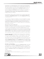
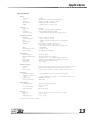
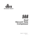
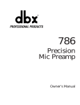
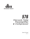
Compressor/
Limiter
262
Operation
Manual
WARNING
CAUTION
FOR YOUR PROTECTION, PLEASE READ THE FOLLOWING:
RISK OF ELECTRIC SHOCK
DO NOT OPEN
A T T E N T I O N : RISQUE DE CHOC ELECTRIQUE - NE PAS OUVRIR
W A R N I N G : TO REDUCE THE RISK OF FIRE OR ELECTRIC
SHOCK DO NOT EXPOSE THIS EQUIPMENT TO RAIN OR MOISTURE
The symbols shown above are internationally accepted symbols that warn of
potential hazards with electrical products. The lightning flash with arrowpoint in
an equilateral triangle means that there are dangerous voltages present within
the unit. The exclamation point in an equilateral triangle indicates that it is necessary for the user to refer to the ownerÕs manual.
These symbols warn that there are no user serviceable parts inside the unit.
Do not open the unit. Do not attempt to service the unit yourself. Refer all servicing to qualified personnel. Opening the chassis for any reason will void the
manufacturerÕs warranty. Do not get the unit wet. If liquid is spilled on the unit,
shut it off immediately and take it to a dealer for service. Disconnect the unit
during storms to prevent damage.
WATER AND MOISTURE: Appliance should not be used near water (e.g. near a
bathtub, washbowl, kitchen sink, laundry tub, in a wet basement, or near a swimming
pool, etc). Care should be taken so that objects do not fall and liquids are not spilled
into the enclosure through openings.
POWER SOURCES: The appliance should be connected to a power supply only of
the type described in the operating instructions or as marked on the appliance.
GROUNDING OR POLARIZATION: Precautions should be taken so that the grounding or polarization means of an appliance is not defeated.
POWER CORD PROTECTION: Power supply cords should be routed so that they are
not likely to be walked on or pinched by items placed upon or against them, paying
particular attention to cords at plugs, convenience receptacles, and the point where
they exit from the appliance.
SERVICING: To reduce the risk of fire or electric shock, the user should not attempt
to service the appliance beyond that described in the operating instructions. All other
servicing should be referred to qualified service personnel.
FOR UNITS EQUIPPED WITH EXTERNALLY ACCESSIBLE FUSE RECEPTACLE:
Replace fuse with same type and rating only.
U.K. MAINS PLUG WARNING
ELECTROMAGNETIC COMPATIBILITY
A moulded mains plug that has been cut off from the cord is unsafe. Discard the
mains plug at a suitable disposal facility. NEVER UNDER ANY CIRCUMSTANCES SHOULD YOU INSERT A DAMAGED OR CUT MAINS PLUG INTO
A 13 AMP POWER SOCKET. Do not use the mains plug without the fuse cover
in place. Replacement fuse covers can be obtained from your local retailer.
Replacement fuses are 13 amps and MUST be ASTA approved to BS1362.
This unit conforms to the Product Specifications noted on the Declaration of
Conformity. Operation is subject to the following two conditions:
¥ this device may not cause harmful interference, and
¥ this device must accept any interference received, including interference
that may cause undesired operation. Operation of this unit within significant electromagnetic fields should be avoided.
¥ use only shielded interconnecting cables.
SAFETY INSTRUCTIONS
NOTICE FOR CUSTOMERS IF YOUR UNIT IS EQUIPPED WITH A POWER
CORD.
DECLARATION OF CONFORMITY
ManufacturerÕs Name:
ManufacturerÕs Address:
WARNING: THIS APPLIANCE MUST BE EARTHED.
dbx Professional Products
8760 S. Sandy Parkway
Sandy, Utah 84070, USA
The cores in the mains lead are coloured in accordance with the following code:
declares that the product:
GREEN and YELLOW - Earth
BLUE - Neutral
BROWN - Live
As colours of the cores in the mains lead of this appliance may not correspond
with the coloured markings identifying the terminals in your plug, proceed as follows:
¥ The core which is coloured green and yellow must be connected to the
terminal in the plug marked with the letter E, or with the earth symbol, or
coloured green, or green and yellow.
¥ The core which is coloured blue must be connected to the terminal
marked N or coloured black.
¥ The core which is coloured brown must be connected to the terminal
marked L or coloured red.
This equipment may require the use of a different line cord, attachment plug, or
both, depending on the available power source at installation. If the attachment
plug needs to be changed, refer servicing to qualified service personnel who
should refer to the table below. The green/yellow wire shall be connected
directly to the unit's chassis.
CONDUCTOR
WIRE COLOR
Normal
Alt
L
LIVE
BROWN
BLACK
N
NEUTRAL
BLUE
WHITE
E EARTH GND GREEN/YEL
GREEN
WARNING: If the ground is defeated, certain fault conditions in the unit or in the
system to which it is connected can result in full line voltage between chassis
and earth ground. Severe injury or death can then result if the chassis and
earth ground are touched simultaneously.
dbx 262
conforms to the following Product Specifications:
Safety:
EN 60065 (1993)
IEC65 (1985) with Amendments 1, 2, 3
EMC:
EN 55013 (1990)
EN 55020 (1991)
Supplementary Information:
The product herewith complies with the requirements of the
Low Voltage Directive 73/23/EEC and the EMC Directive
90/336/EEC as amended by Directive 93/68/EEC.
dbx Professional Products
Vice-President of Engineering
8760 S. Sandy Parkway
Sandy, Utah 84070, USA
February 6, 1997
European Contact: Your Local dbx Sales and Service Office or
International Sales Office
68 Sheila Lane
Valparaiso, Indiana
46383, USA
Tel: (219) 462-0938
Fax: (219) 462-4596
Table of Contents
Warranty
............................. 2
Introduction . . . . . . . . . . . . . . . . . . . . . . . . . . . . 2
Inspection . . . . . . . . . . . . . . . . . . . . . . . . . . . . . 3
Front Panel Operation . . . . . . . . . . . . . . . . . . . . 3
Rear Panel Operation . . . . . . . . . . . . . . . . . . . . . 5
Connections . . . . . . . . . . . . . . . . . . . . . . . . . . . . 5
Operating Notes . . . . . . . . . . . . . . . . . . . . . . . . . 6
Applications . . . . . . . . . . . . . . . . . . . . . . . . . . . . 7
Specifications . . . . . . . . . . . . . . . . . . . . . . . . . . .13
¨
8760 South Sandy Parkway
Sandy, Utah 84070 USA
Tel: (801) 568-7660
Fax: (801) 568-7662
E•Mail: [email protected]
Home Page: http://www.dbxpro.com
International Sales
68 Sheila Lane
Valparaiso, Indiana
46383 USA
Tel: (219) 462-0938
Fax: (219) 462-4596
Compressor/
Limiter
262
1
Warranty and Introduction
Warranty
1. The warranty registration card must be mailed within 30 days after purchase
date to validate this warranty and proof-of-purchase is considered to be the
burden of the consumer.
2. dbx warrants this product, when bought and used solely within the U.S., to
be free from defects in materials and workmanship under normal use and
service.
3. dbx liability under this warranty is limited to repairing or replacing defective
materials that show evidence of defect, provided the product is returned to
dbx WITH RETURN AUTHORIZATION from the factory, where all parts and
labor will be covered up to a period of two years. A Return Authorization
number may be obtained from dbx by telephone. The company shall not be
liable for any consequential damage as a result of the product's use in any
circuit or assembly.
4. dbx reserves the right to make changes in design or make additions to, or
improvements upon this product without incurring any obligation to install
the same on products previously manufactured.
5. The foregoing is in lieu of all other warranties, expressed or implied, and
dbx neither assumes nor authorizes any person to assume for it any obligation or liability in connection with the sale of this product. In no event shall
dbx or its dealers be liable for special or consequential damages or from any
delay in the performance of this warranty due to causes beyond their control.
Introduction
2
We congratulate and thank you for your purchase of the dbx 262
Compressor/Limiter. The 262 provides two channels of classic dbx compression
at an unheard of price and boasts features found on our industry standard compressor/limiters, such as:
• OverEasy®/Hard Knee Selection - allows selection between our famous
OverEasy® compression curve and the classic “Hard Knee” curve popularized
by the original dbx 160, 161, and 162.
• True RMS Level Detection - senses the power in the program in a musical
manner, much as the ear does, giving results superior to peak or average
detection.
• True RMS Power Summing™ - When the two channels of the 262 are stereo
coupled together, the RMS energy of the two signals is intelligently summed
together in a way that prevents phase cancellation of the two signals which
would normally cause unmusical compressor action.
• Balanced 1/4” TRS Inputs and Outputs can be used with pro and semi-pro,
balanced or unbalanced systems..
• DC-Controlled Parameters - the signal does not pass through any of the front-
Inspection and Front Panel
panel controls. Instead, a DC voltage controls all functions; this eliminates any
possibility of potentiometer noise developing over time.
Although the dbx 262 was designed to be the easiest stereo compressor/limiter
on the market to use, we suggest that you read this operation manual to fully
understand the 262's power. We have kept the manual simple and easy to read
so that you can get back to work quickly.
We know you'll enjoy your 262 and thanks again for purchasing a quality dbx
product.
Inspection
Before continuing any further, please inspect the contents of the dbx 262 box to
be sure that the following items are included:
• dbx 262 Compressor/Limiter
• Operation Manual (yes, you are already reading it)
• Registration/Warranty card
• 4 Rack Screws and Washers
• Power Cord
If anything is missing, please notify your dealer.
The information contained in this manual is subject to change at any time without notification.
C H A N N E L
O N E
C H A
-10
-20
4:1
0
0
6:1
3:1
:1
-10
-30
2:1
+10
+10
-40
dBu
+20
THRESHOLD
O
STEREO
COUPLE
-4:1
OVEREASY
+
1:1
-2:1
-1:1
RATIO
30
-20
dB
25
GAIN REDUCTION dB
20 15 10
6
3
-3
BYPASS
1
+20
OUTPUT GAIN
BYPASS Switches and LEDs: In Bypass mode, the 262’s processing and controls are disabled, presenting unaltered input signal at the 262’s output. The
bypass mode for each channel works independently, even when in stereo couple mode. Bypass mode is especially useful for making comparisons between
processed and unprocessed signals. When bypassed, the red LED adjacent to
the switch is lit.
Front Panel
Operation
THRESHOLD Control: Adjust this control to set the threshold of compression
from -40 to +20 dBu.
Compressor/
Limiter
262
3
Front Panel
OverEasy® Switch: OverEasy® provides a smooth transition from the compressor’s linear region to the compressed region. This smooth transition greatly
reduces compression artifacts and allows faster attack times and higher compression ratios while still maintaining the natural characteristics of the signal.
The switch lights to indicate OverEasy® processing is enabled. Figure 1 below
illustrates the the input/output relationships for OverEasy® operation. Figure 2
illustrates the same for hard knee operation. When conventional hard knee processing is desired, disable the OverEasy® function
.
1:1
1:1 Unity
+15
2:1
+10
4:1
+5
:1
0
B
AM
-5
-15
RED
Above Threshold
EN
OverEasy Range
RE
-10
ER
OUTPUT LEVEL (dB)
+20
Below Threshold
-15 -10 -5
0
+5 +10 +15 +20
RED
Above Threshold
+15
2:1
+10
4:1
+5
20:1
0
:1
Rotation Point Threshold
-5
-10
G
OUTPUT LEVEL (dB)
+20
-15
GREEN
Below Threshold
-15 -10
-5
0
+5 +10 +15 +20
INPUT LEVEL (dB)
INPUT LEVEL (dB)
Fig. 1 -OverEasy®
Fig. 2 - Hard Knee
THRESHOLD LEDs: These three LEDs indicate the relationship of the input
signal level to the threshold of compression. The green “below” (-) LED is on
when the signal is below threshold and the red “above” (+) LED is on when the
signal is above threshold. When the 262 is switched to OverEasy® mode, the
amber “O” LED is on when the signal is in the OverEasy® region (See Figure
1).
COMPRESSION RATIO Control: This control selects the ratio between input
and output levels for signals above the threshold. Rotate this control clockwise
to increase the amount of compression from 1:1 (no compression) up to infinity:1 (no increase in output level, regardless of input level increases above
threshold); further clockwise rotation increases compression into the INFINITY+™ region, up to a maximum of -1:1 (i.e., a 1dB increase in input level
above threshold causes a 1dB decrease in output level). In the INFINITY+™
region, the 262 inverts the program dynamics for special effects. Figures 1 and 2
illustrate input/output slopes corresponding to various compressor/limiter ratio
settings.
OUTPUT GAIN Control: Adjust this control to vary the amount of fixed gain
(up to ±20 dB) in the 262’s output amplifier stage. The OUTPUT GAIN control
does not interact with the threshold of compression.
GAIN REDUCTION Meter: This 8-segment LED meter indicates the amount of
gain reduction due to compression/limiting, ranging from 0 to 30 dB.
STEREO COUPLE Switch and LED: This switch changes the 262 from two
independent compressors into a stereo compressor. In Stereo mode, Channel 1
4
Rear Panel and Connections
is the master, and Channel 2 is the slave. Each of the Channel 2 controls and
switches will be overridden and controlled by Channel 1 except the Bypass
switch which will remain independent. Also, Channel 2’s 3-LED Threshold Meter
will be disabled, while both channels’ Gain Reduction Meters will identically
indicate the amount of gain reduction occurring. It is important to note that
while Channel 1 is the master as far as the controls go, both channels have
equal precedence as far as signal processing is concerned. The 262 uses True
RMS Power Summing™, an extremely accurate and musical way to combine
detector outputs in a stereo situation. The LED adjacent to the switch will be lit
when switched to stereo couple mode.
15 WATTS
CHANNEL TWO
¨
CAUTION
RISK OF E L E CT RIC SHOCK
DO NOT OPE N
PROFESSIONAL PRODUCTS
100V
50/60Hz
120V
60Hz
A HARMAN INTERNATIONAL
COMPANY
SALT LAKE CITY, UTAH
MADE IN USA
MODEL 262
OUTPUT
A T T E N T I O N : RISQUE DE CHOC E L E CT RIQUE -NE PAS OUVRIR
INPUT
BAL /
UNBAL
CHANNEL ONE
OUTPUT
INPUT
BAL /
UNBAL
W A R N I N G : T O RE DUCE T HE RISK OF F IRE OR E L E CT RIC
SHOCK DO NOT E XPOSE T HIS E QUIPME NT T O RAIN OR MOIST URE
INPUT Jacks: The input jacks accept a standard 1/4” TRS phone plug for a
balanced input source, or a standard 1/4” TS phone plug for an unbalanced
source.
Rear Panel
Operation
OUTPUT Jack: The output jacks accept a standard 1/4” TRS phone plug for driving balanced lines, or a standard 1/4” TS phone plug for driving unbalanced
lines.
AC Power Receptacle: This receptacle accepts an IEC-type power cord (as
shipped with the unit). Check that the AC power markings below the AC power
connector are correct for your area. (Either 100/120V, or 230V.) Plug the cord
into the unit and mains power. Note that the 262 does not have a power
switch. It is recommended that the 262 be “On” at all times. Power consumption is low. If you do not plan to use the 262 for an extended period of time,
unplug it. Connection to an inappropriate power source may result in
extensive damage which is not covered by the warranty.
The 262 has balanced inputs and outputs, and can be used with any line-level
device. Some common examples include: mixing consoles, patch bays and
other signal processors.
Connections
For all connections, refer to the following steps:
1. Turn off all equipment before making any connections.
2. Mount the 262 in a 1U rack space (optional).
The 262 requires one rack space (height). It can be mounted above or below
anything that doesn’t generate excessive heat, since it requires no special ventilation. Ambient temperatures should not exceed 113˚F (45˚C) when equipment
Compressor/
Limiter
262
5
Operating Notes
is powered.
Caution: Never remove the cover. There are no user-serviceable parts inside,
and you run the risk of an electric shock.
3. Make balanced or unbalanced connections via 1/4” TRS jacks according to
your requirements.
4. Check the line voltage: The unit is shipped for either 100-120V or 230V,
50/60 Hz operation (ie: not both). Refer to the unit’s rear panel AC power connector to verify that the voltage is correct for your area. Securely connect the
AC power cord to the unit and mains power.
Operating Notes
Using the THRESHOLD Control
In Hard Knee mode (OverEasy® switch out), THRESHOLD sets a reference
level above which input signals will be processed by the 262’s gain change circuitry in the manner defined by the setting of the RATIO control. Input signals
which fall below this level will pass through the 262 unprocessed (except for
fixed gain changes directed by the OUTPUT GAIN control).
In OverEasy® Mode (OverEasy® switch depressed), signals begin to gradually
activate the 262’s gain change circuitry as they approach the THRESHOLD reference level and do not get fully processed in the manner defined by the RATIO
control until they have passed somewhat above the THRESHOLD reference
level. In OverEasy® mode there is no distinct point at which processing begins,
and the THRESHOLD setting corresponds to a point on the input/output transfer curve midway between the onset of processing and that point at which the
transfer curve corresponds to the setting of the RATIO control. Figure 1 on page
4 shows the OverEasy® compression curves and how they correlate with the
THRESHOLD LEDs. Similarly, Figure 2 on the same page illustrates the
THRESHOLD LED operation for the Hard Knee mode.
Using the COMPRESSION RATIO Control
When an input signal is above the THRESHOLD reference level, the setting of
this control determines the number of decibels by which the input signal must
change in level to produce a 1 dB increase in the signal level at the output of
the 262. A setting of 2:1 indicates an input:output ratio wherein a 2 dB increase
in signal (above threshold) will produce a 1 dB increase in output signal. A setting of °:1 indicates that an infinite increase in input level would be required to
raise the output level by 1 dB. In other words, the output level stays constant
when the input signal rises above threshold.
The 262’s RATIO control covers the entire range from 1:1 to °:1 and, in addition, goes to Infinity+™ (negative) ratios. At a setting of -1:1, the above threshold input signal must increase by 1 dB in level to decrease the signal at the output of the 262 by 1 dB. See Figure 3 below. The control curve of the RATIO
potentiometer has been designed to provide total operator control, with scale
expansion at the subtle, lower ratios for easy, repeatable settings.
6
Operating Notes and Applications
¥
-
OUTPUT LEVEL (dB)
1:1
-
+20
+15
2:1
+10
4:1
+5
¥:1
0
-5
Threshold
-10
-1:1
-15
-15 -10
-5
0
+5 +10 +15 +20
INPUT LEVEL (dB)
Figure 3: Ratio Control and Infinity+™ (Negative) Ratios
Applications
Typical patch points include: a mixer’s channel or subgroup inserts when using
the 262 on individual instruments or tracks; the mixer’s main outputs or bus
inserts when mixing; an instrument preamp’s effects loop when using the 262
for guitar or bass; main outs of a submixer (e.g., drum mixer) as the signal is
sent to main mixer; between a DAT’s output and an analog cassette input.
When using a chain of processors, the 262 may be placed either before or after
effects or dynamic processors. However, if you are using the 262 for speaker
protection, the compressor should be as close to the amplifier as possible in the
signal chain. We recommend you use common sense and experiment with different setups to see which one provides the best results for your needs.
Mixing Board
If you wish to compress a particular track of a multitrack recording or one
channel of a live performance, connect a cable from the audio source’s output
jack to the 262 INPUT, and connect the 262 OUTPUT to a line input jack (balanced or not), or the 262’s INPUT and OUTPUT can be wired to an insert point.
In the latter case, the signals will most likely be unbalanced as is typical of
most insert signals.
Note: The amount of compression is directly related to the level of the input
signal. However, depending upon your system’s setup, it may not always be
crystal clear as to which volume controls in your chain affect input level and
which affect output level. If the 262, in relation to your mixer channel’s volume
controls, is “pre-fader” (i.e., the 262 is connected to mixer inserts so that the
compression effect occurs before the mixer channel’s volume fader), you can
boost or cut the input level by adjusting the mixer channel source’s volume
control (e.g., a synthesizer’s volume control) and vary the track’s output level
using either the 262’s OUTPUT GAIN control or the mixer channel’s volume
fader (the latter here is great for track fade-outs). Keep in mind that it is best to
set the OUTPUT GAIN of the 262 to achieve a “nominal” level that the mixer
channel would like to “see” and use the channel fader to change levels. This
method maintains proper signal levels through the channel and avoids either
running out of headroom (clipping) or increasing noise by running the channel
Compressor/
Limiter
262
7
Applications
signal too low.
If the 262 is “post fader” (i.e., the 262 is connected to mixer inserts so that the
compression effect occurs after the level set by the mixer channel’s volume
fader), adjusting the mixer’s volume fader changes the input level and the
amount of compression. If you would rather have this volume fader control output, we suggest you set up the compressor directly between the source and the
mixer channel’s input. This way, you can use the instrument’s volume control to
define the input level and amount of compression and the mixer’s volume fader
to change only the overall volume of the track.
Musical Instruments (e.g., Electric Guitar, Bass, Keyboards, ElectricAcoustic Instruments)
The output of an electric guitar is sometimes not “hot” enough to drive the
262’s INPUT. When this is the case, you should use the “PREAMP OUT” of your
guitar amp (if so equipped), or the output of some other device that is designed
to accept low-level instrument inputs (including various foot pedal effects,
acoustic pickup preamps, and rack mount audio products, like the dbx 163A
and 263A). Such sources can be balanced or unbalanced - this is no problem
for the 262.
With most setups these low-level sources require signal boost to drive the 262’s
INPUT. For example, when recording voice directly to a portable tape deck, a
mic preamp (like the dbx 760X) placed between the mic and the 262 (which is
then fed to one of the recorder’s inputs) can boost the low-level signal to a
line-level required by the 262.
Keyboards, samplers, drum machines and sound modules typically produce a
line-level signal and can be connected directly from the instrument’s output to
the 262’s INPUT.
Note: DO NOT CONNECT the output of a power amp or the speaker out of an
instrument to the input of the 262. Severe damage to system components may
result.
Patch Bay
In the studio, the 262 may be connected to a patch bay to allow it to be
patched anywhere in the studio system.
Sound Reinforcement
To compress a live mix or to protect loudspeakers, connect the 262 between
the source (mixing board or distribution amp) and the power amp(s). If multiway loudspeakers with low-level electronic crossovers are used, the 262(s)
should go after the crossover(s). For a stereo system, you can separately stereo
couple the two high band crossovers, low band crossovers, etc.
Specific Applications
Note: The following control settings for each application are suggested as a
starting point. Adjust them for your requirements.
Smoothing Out Variations in Microphone Levels
Variations in signal level can occur when the distance between a vocalist and a
8
Applications
mic changes, or when the dynamics of a voice changes relative to a vocalist’s
range. To smooth out these variations, start with the 262 in OverEasy® mode
and adjusted for a low to medium COMPRESSION RATIO (e.g., 4:1). Adjust the
THRESHOLD control so that the GAIN REDUCTION meters show 6 dB to 10 dB
of gain reduction, then increase the COMPRESSION RATIO if necessary. Due to
the gentle OverEasy® characteristic of your 262 you will find that even fairly
high ratios are handled transparently.
Smoothing Out Variations (and Increasing Sustain) in Musical Instrument
Levels
To achieve a smoother electric (or electronic) bass sound, compress the instrument’s output with a COMPRESSION RATIO of approximately 4:1, then adjust
the THRESHOLD control for 10dB to 12dB of gain reduction. Compression
lessens the loudness variations among the strings and increases the bass’ inherent sustain. Other instruments, such as horns, vary in loudness depending on
the note being played, and benefit similarly.
To control untimely volume shifts in “hot” guitar or synth parts and to keep
them from overloading your tape deck or mixer during recording and live performances, start with the COMPRESSION RATIO at approximately 5:1 and the
THRESHOLD set to the average maximum level of the track. This will ensure
that only the offending “hot” part is compressed. Adjust both controls as necessary.
To add sustain to guitar or synthesizer string sounds, begin with a higher COMPRESSION RATIO (from 10:1 to °:1), then adjust the THRESHOLD control to
taste. For example, you can use a compressor to alter the envelope of a synth
patch to create an otherworldly synth pad that has just the right amount of
body and soul without losing its initial impact: begin with a synth sound that
has a bite on its attack, but ends with a long release time. While playing slow,
but steady, synth stabs or chords, compress the sound heavily; adjust the
THRESHOLD to taste and toggle between OverEasy® and Hard Knee modes to
hear the effect each mode has on the attack and release of the envelope. Heavy
compression of guitars and synths, as they are being recorded to digital formats,
can often help revive their sense of “analog life.”
Negative ratios alter the envelope of a sound differently than high compression
ratios. With the 262 in the path of a synth or guitar, set the COMPRESSION
RATIO to -1:1, -2:1 or -5:1. Methodically strike a series of chords and listen to
how the compression softens the attack and quickens the release. Adjust the
THRESHOLD and experiment with different types of sounds and 262 settings.
Negative ratios can also be used to prevent musicians from continually increasing the volume of their instrument (e.g., in live applications where there is no
sound engineer to control the house levels). With their signal compressed by a
negative COMPRESSION RATIO, each volume increase initiated at the instrument or amp would actually decrease the volume level at the final mix.
Fattening Kick Drums and Compressing Other Drums
Weak, flabby kick drums often have too much boom, and not enough slap. To
tighten them up, start with the 262 adjusted for a medium to high COMPRESSION RATIO (e.g., 6:1), adjust the THRESHOLD control so that the GAIN
Compressor/
Limiter
262
9
Applications
REDUCTION meters show 15dB of gain reduction, then increase the COMPRESSION RATIO if necessary. In OverEasy® mode, the 262 takes slightly longer to
react than in Hard Knee mode, and will therefore emphasize the slap at the
beginning of the note and reduce the boominess of its body. The 262 also
works well for tightening snare drums and tom toms and can be used with
drum machines to effectively alter the character of any electronic drum sound.
For drum kit submixes (e.g., mixing multiple drum tracks to two tracks while
using two 262s for compression), consider backing off the COMPRESSION
RATIO on each 262 (down to 2:1) to avoid an excess of cymbal “splattering.” In
larger multitracking systems, compress the kick and snare separately. A further
possibility (if you have two more compressors) is to heavily compress a stereo
submix of toms and leave the remaining percussives unaffected.
Raising a Signal Out of a Mix
Since reducing dynamic range increases the average signal level by a small
amount, a single track can be raised out of a mix by boosting its level slightly
and applying compression. Start with a 2:1 COMPRESSION RATIO and a relatively low THRESHOLD setting (-20dB). Adjust both controls as necessary.
Compressors have also been used to bring vocals to the forefront of a mix in
volume-restricted studios (e.g. home studios). Start by adding a foam windscreen to the mic (if it doesn’t have one). Set the COMPRESSION RATIO to 10:1
and the THRESHOLD to -10dB. With your mouth approximately 2 inches from
the mic, sing the vocal part, but with less volume than normal. Use phrasing to
give the part some intensity. An equalizer (e.g., a dbx 3031 Graphic Equalizer)
or a vocal effects device (e.g., dbx 290, delay, distortion) can be added to further toughen the performance.
Note: When compressing stereo program material, the factors affecting a compression curve and the actual COMPRESSION RATIO and THRESHOLD settings,
are like those previously covered with reference to single channels of program
material. However, it will generally be found that large amounts of compression
are more audible in a mixed stereo program than they might be on the separate
tracks that were mixed to create the program.
Preventing Tape Saturation
With programs of widely varying levels, compression can prevent recording levels (e.g., cymbal tracks in a final mix or drum kit submix) from saturating tape
tracks.
Preventing Digital Overload
Digital recorders and samplers produce audible distortion when they exceed
their headroom. The 262 effectively ensures that audio input does not overload
a digital recorder’s D/A (digital-to-analog) converters. The 262 can perform this
compression quietly enough for all digital media. Set the 262 for limiting with
Hard Knee mode On, the COMPRESSION RATIO to °:1, and set the THRESHOLD 2 to 3 dB below the overload point of the recorder.
Speaker Protection (Auditoriums, Churches, Mobile DJs and Sound
Systems)
Compressors are frequently used to prevent excessive program levels from dam-
10
Applications
aging drivers in a sound-reinforcement system (whether you’re doing auditorium, church, or club sound engineering, or are a mobile DJ for small dances, or
like to push the limits of your home’s audio entertainment center). Set the 262
for limiting (Hard Knee mode On, with a COMPRESSION RATIO of 10:1 or
greater) and adjust the THRESHOLD to provide 15dB or more of compression
(just a few dB below the input clip). For low-level signals, the 262 won’t
change gain, but if large signals come along, the gain will be reduced to prevent clipping and save sensitive system components from excessive heat
buildup or other type of damage.
In circumstances where the 262 is expected to cause no change in gain unless
an emergency arises (wildly excessive levels), some operators set Hard Knee
mode On, the COMPRESSION RATIO to °:1, and the THRESHOLD to the highest permissible level.
As a general rule, compressors should be as close to the amplifiers as possible
in the signal chain. If the 262 is placed before the EQ (equalizer), for example,
a potentially damaging boost in the EQ won’t be seen by the 262 and the
speakers may be damaged. For maximum sound pressure levels, large sound
reinforcement systems frequently use a separate compressor on each output of
the electronic crossover(s).
Raising Average Level in PA Systems
Limiting (i.e., compression at high ratios like °:1) also benefits intelligibility by
allowing low-level input signals to be reproduced through the system at higher
volume. In a musical performance, this provides additional intimacy as the
vocalist’s whispers are heard clearly at every seat in the house. The OverEasy®
curve available with the 262 permits a very high amount of compression (COMPRESSION RATIO of 10:1 or greater) to be used in many situations. This allows
dynamic speakers, vocalists and other musicians to concentrate on their presentation or performance without worrying about the ill effects of volume changes.
Using Your EQ to Reduce Feedback in Live Settings (Indoor and Outdoor
Concerts, Churches)
You can use your 262 and EQ (equalizer) to reduce feedback in clubs, churches, outdoor concerts and other live settings. Patch or insert the 262 into the
main output of a mixer, set the 262 to Hard Knee mode and slowly increase the
console gain control until the first feedback “ring” occurs, then set up the 262
with its COMPRESSION RATIO at °:1 and THRESHOLD low. The 262 will catch
the first feedback ring and hold it as a constant tone so you can adjust your EQ
to minimize it. Continue to increase your console gain and set your EQ until the
next 3 or 4 “ring” frequencies have been compensated for.
The 262 as a Line Amplifier
To use the 262 as a line amplifier, adjust the COMPRESSION RATIO control fully
counterclockwise (1:1 position), THRESHOLD fully clockwise (+20) and OUTPUT GAIN to whatever setting is required for the application. Remember, excessive gain may lead to output clipping of high level signals. To add compression,
adjust the COMPRESSION RATIO and the THRESHOLD controls to the desired
settings.
Increasing Sustain
To increase the sustain of a musical instrument (e.g., a guitar or bass). Set the
Compressor/
Limiter
262
11
Applications
262 to Hard Knee mode, with a fairly low THRESHOLD and a moderate COMPRESSION RATIO.
Stereo Couple
The ability to choose between dual mono or stereo coupled operation allows
flexibility in a variety of situations. Use dual mono (uncoupled) operation when
processing independent signals such as individual instruments or on channel
inserts of a mixer. Use stereo coupled operation when simultaneously processing stereo L/R signals such as mastering to tape or compressing the stereo L/R
outputs of a live mixing console. Stereo coupling not only allows identical control of both channels from one set of master controls, but it causes identical
gain reduction in both channels. This is not only desirable, but necessary to
maintain the stereo image. If the left and right channels’ gains were allowed to
change independently, the stereo image would audibly shift away from the
channel in which gain reduction is occurring, toward the channel in which less
(or no) gain reduction is occurring.
To provide the most pleasing and accurate signal dynamics, dbx processors use
True RMS Power Summing™. This means that, in stereo couple mode, signals
above the compressor threshold in either channel cause gain reduction in both
channels. This ensures that the protective or creative action of the compressor is
maintained for both channels, while preserving the integrity of the stereo image.
Additionally, True RMS Power Summing™ allows stereo signals to be combined
without phase cancellation in an intelligent way, interpreting the combined signals the same way the human ear and brain combine and interpret them. The
natural result is the pleasing sound of dbx compression that has become a
world-wide standard.
12
Applications
Specifications
Inputs:
Connectors:
Type:
Impedance:
Max Input Level
CMRR:
1/4” TRS
Electronically balanced/unbalanced, RF filtered
Balanced > 50 k½, unbalanced > 25 k½.
+22 dBu, balanced or unbalanced
> 40 dB, typically > 55 dB at 1 kHz
Outputs::
Connectors:
Type:
Impedance:
Max Output Level:
1/4” TRS
Impedance-balanced/unbalanced, RF filtered
Balanced 200 ½, unbalanced 100 ½
> +21 dBu balanced/unbalanced into 2 k½ or greater
System Performance:
Bandwidth:
Frequency Response:
Noise:
Dynamic Range:
THD+Noise
IMD:
Interchannel Crosstalk:
Stereo Coupling:
20 Hz to 20 kHz, +0/-0.5 dB
< 3 Hz to > 90 kHz, +0/-3 dB
< -92 dBu, unweighted, 22 kHz measurement bandwidth
> 114 dB
0.01% typical at +4 dBu, 1 kHz unity gain
0.09% typical at +20 dBu, 1 kHz, unity gain
< 0.2%, any amount of compression up to 40 dB, 1 kHz
< 0.2% SMPTE
< -90 dB at 1 kHz
True RMS Power Summing™
Compressor:
Threshold Range:
Threshold Characteristic:
Ratio:
Attack Time:
Release Time:
Output Gain:
-40 dBu to +20 dBu
Selectable OverEasy® or hard knee
1:1 through °:1 to -1:1; > 60 dB maximum compression
Typically 15 ms for 10 dB, 5ms for 20 dB, 3 ms for 30 dB
Program-dependent, 125 dB/sec rate
-20 to +20 dB
Function Switches:
OverEasy®
Bypass:
Stereo Couple:
Activates the OverEasy® compression function, one switch per channel.
Electronically disables gain reduction, one switch per channel.
Couples channels for stereo operation. Channel One is the master.
Indicators:
Gain Reduction Meter:
Compressor Threshold
Meter:
Bypass Switch:
Stereo Couple Switch:
Power Supply:
Operating Voltage:
Power Consumption:
Mains Connection:
Physical:
Dimensions:
Weight
Shipping Weight:
8-segment LED bar graph at 1,3,6,10,15,20,25, and 30 dB
3-segment LED bar graph at Below (-), OverEasy® (O), and Above (+)
Red LED per channel
Amber LED
100VAC 50/60 Hz, 120VAC 60 Hz
230 VAC 50/60 Hz
15 Watts
IEC 320 receptacle
1.75” H X 19” W X 6.9”D (4.4cm x 48.3 cm x 17.5cm)
3.6 lbs. (1.6 kg)
5.3 lbs. (2.4 kg)
Note: Specifications subject to change
Compressor/
Limiter
262
13
¨
8760 South Sandy Pkwy.
Sandy, Utah 84070
Phone: (801) 568-7660
Fax: (801) 568-7662
IntÕl Phone (219) 462-0938
IntÕl Fax: (219) 462-4596
A Harman International Company
Questions or comments?
E¥mail us at: [email protected]
or visit our World Wide Web home page at:
http://www.dbxpro.com
2/6/97
Part Number: 18-2152-B