1
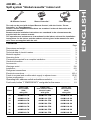
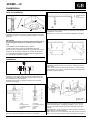
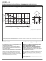
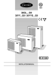
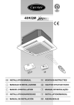
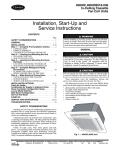
40KMC---N
AM
PM
INSTALLATION MANUAL
IR Remote Control
“Room Controller”
“Zone Manager”
The unit can be used with infrared Remote Control, with the Carrier “Room
Controller” or “Zone Manager”.
Infrared control installation instructions are contained in the unit instruction and
maintenance manual.
Remote controls intallation instructions are contained in the relevant manuals,
supplied with the remote controls.
The operation and maintenance instructions for the indoor unit and the installation
instructions for the indoor and the outdoor unit are given in the manuals for each
unit. These are supplied with the unit.
Contents
Page
Dimensions and weight.........................................................................................
2
Technical data .......................................................................................................
3
Technical data of electric heaters .........................................................................
3
Material supplied ..................................................................................................
3
Operating limits .....................................................................................................
3
Components required for a complete installation .................................................
3
General information ..............................................................................................
4
Accessories ..........................................................................................................
4
Warnings: avoid ....................................................................................................
5/6
Installation ............................................................................................................
6/8
Refrigerant connections .......................................................................................
9
Electrical connections ........................................................................................... 10/14
Fresh air renewal and conditioned air supply to adjacent room ........................... 15/16
System configuration ............................................................................................
17
Operating test, address switch and address selector .................................
18
Fault code, button T: “EMERGENCY” and guide for the owner ..................
19
Indoor unit
item number
50Hz
with grille
Indoor unit
item number 50Hz +
electric heater
with grille
Indoor unit
item number
60Hz
with grille
12
40KMC012-7N
40KMC112-7EN
40KMC012-3N
18
40KMC018-7N
40KMC118-7EN
40KMC018-3N
24
40KMC024-7N
40KMC124-7EN
40KMC024-3N
28
40KMC028-7N
40KMC328-7EN
40KMC028-3N
36
40KMC036-7N
40KMC336-7EN
40KMC036-3N
48
40KMC048-7N
40KMC348-7EN
40KMC048-3N
60
40KMC060-7N
40KMC360-7EN
40KMC060-3N
Sizes
ENGLISH
40KMC---N
Split system “Global cassette” indoor unit
GB - 1
40KMC---N
Dimensions and weight
575
575
91
70
158
0
Ø
Ø
15
225
280
298
120
52
56
720
40KMC 012N - 018N - 024N
515
550
30
Ø 25
50
825
168
237
Ø
298
15
0
120
825
595
150
40KMC 028N - 036N - 048N - 060N
960
813
Ø 100
66
Ø 25
48
40KMC---7N
Unit
Frame / Grille assembly
GB - 2
kg
012
17,5
3
018
19
3
024
19
3
028
36
5
036
38
5
048
38
5
060
41
5
40KMC---N
Technical data
ENGLISH
Table I: Nominal data
POWER INPUT (WATT)
Sizes
12
18
24
28
36
48
60
standard
40KMC012-7N
40KMC018-7N
40KMC024-7N
40KMC028-7N
40KMC036-7N
40KMC048-7N
40KMC060-7N
Sizes
with electric heaters
12
18
24
28
36
48
60
40KMC112-7EN
40KMC118-7EN
40KMC124-7EN
40KMC328-7EN
40KMC336-7EN
40KMC348-7EN
40KMC360-7EN
POWER INPUT (WATT)
Cooling only
Cooling
75
80
105
107
131
178
231
Cooling
75
80
105
107
131
178
231
Heat pump
Heating
75
80
105
107
131
178
231
Heating
1575
2580
2605
3107
3131
3178
3231
standard
40KMC012-7N
40KMC018-7N
40KMC024-7N
40KMC028-7N
40KMC036-7N
40KMC048-7N
40KMC060-7N
Sizes
12
18
24
28
36
48
60
Sizes
with electric heaters
12
18
24
28
36
48
60
40KMC112-7EN
40KMC118-7EN
40KMC124-7EN
40KMC328-7EN
40KMC336-7EN
40KMC348-7EN
40KMC360-7EN
Cooling
75
80
105
107
131
178
231
Cooling
75
80
105
107
131
178
231
Heating
75
80
105
107
131
178
231
Heating
1575
1580
1605
2107
2131
2178
2231
Note: For power supply wire size and delay type fuses, refer to the outdoor unit installation instructions.
Table II: Technical data of electric heaters (if installed)
Mod.
12
18
Heat pump
24
28
36
Electric heater
capacity
kW
1.5
1.5
1.5
Supply voltage
V
Max. current draw
Control device
A
Safety thermostat
Power supply cables
mm2
Recommended fuse (gL type) A
48
60
2 x 1.0 2 x 1.0 2 x 1.0 2 x 1.0
12
Cooling only
24
28
36
18
48
60
1.5
1.5
1.5 2 x 1.0 2 x 1.0 2 x 1.0 2 x 1.0
+
+
+
+
+
+
1.0
1.0 2 x 0.5 2 x 0.5 2 x 0.5 2 x 0.5
230
230
230
230
230
230
230
230
230
230
400
400
400
400
(*)
(*)
(*)
(*)
(*)
(*)
3N
3N
3N
3N
6.5
6.5
6.5
8.8
8.8
8.8
8.8
6,5
10.8
10.8
7.5
7.5
7.5
7.5
GMC electronic control
N° 1 Manual reset thermostat ST1 60°C
N° 1 Manual reset thermostat ST2 100°C
3 G 1.5 3 G 1.5 3 G 1.5 4 G 1.5 4 G 1.5 4 G 1.5 4 G 1.5 3 G 1.5 3 G 2.5 3 G 2.5 5 G 1.5 5 G 1.5 5 G 1.5 5 G 1.5
8
8
8
8
8
8
8
8
12
12
10
10
10
10
*In areas with a 2 kW limit for single-phase electric heaters it is possible to divide the power supply on two phases and neutral of a three phase supply with neutral.
Use cable type H07 RN-F - 4G1,5 mm2 - 400V 2N ~
Table III:
Material supplied
Description
Quantity
Installation instructions
Owner's Manual
Fresh air intake baffle
1
1
1
Use
Indoor unit installation
Correct use
Air renewal
Table IV: Operating limits
Cooling / Heating
Main power supply
Electric heater
Refer to outdoor unit installation manual.
Nominal single-phase voltage
230V ~ 50Hz
Operating voltage limits
min. 198V – max. 264V
Nominal three-phase voltage
400V 3N ~ 50Hz
Operating voltage limits
min. 342V – max. 462V
27°C
230V-240V ~ 60Hz
Table V: Components required for a complete installation
Name
Connection pipe
Wall sleeve
Wall cap
Finishing tape
Fastening tape
Tube insulation
Drain hose
Sealer putty
- Outdoor power supply cable
- Electrical connecting cable
between indoor and outdoor unit
Specification
40KMC 012N Ø (1/2") 12.70 mm (Gas) / Ø (1/4") 6.35 mm (Liquid)
40KMC 018N, 024N, 028N, 036N, 048N and 060N Ø (1/2") 12.70 mm (Gas) / Ø (1/4") 6.35 mm (Liquid)
PVC film
I.D. 16 - 17 mm
H07 RN-F (60245IEC66),
cable with synthetic rubber insulation and polychloroprene sheath.
H07 RN-F (60245IEC66),
cable with synthetic rubber insulation and polychloroprenesheath.
GB - 3
40KMC---N
General information
Unit installation
“Operating limits” of the outdoor unit installation manual, will
immediately invalidate the unit warranty.
Read this instruction manual thoroughly before starting
installation.
• Failure to observe electric safety codes may cause a fire hazard in
the event of short circuits.
• This unit complies with the low-voltage (EEC/73/23) and
electromagnetic compatibility (EEC/ 89/336) directives.
• Inspect equipment for damage during transport. In case of
damage file an immediate claim with the shipping company.
Do not install or use damaged units.
• Follow all current national safety code requirements.
In particular ensure that a properly sized and connected ground
wire is in place.
• In case of malfunction turn the unit off, disconnect the mains
power supply and contact a qualified service engineer.
• Check that the voltage and frequency of the mains power supply
are as required for the unit to be installed; the available power
source must be adequate to operate all other appliances
connected to the same line.
Also ensure that national safety code requirements have been
followed for the main supply circuit.
• Connection of the system to the mains power supply is to be
carried out in compliance with the wiring diagram shown in
the installation instructions of the external section.
• Connect indoor and outdoor units with field-supplied copper
pipes by means of flare connections. Use insulated seamless
refrigeration grade pipe only, (Cu DHP type according to
ISO1337), degreased and deoxidized, suitable for operating
pressures of at least 4200 kPa and for burst pressure of at least
20700 kPa. Under no circumstances must sanitary type copper
pipe be used.
• Maintenance of the refrigerant circuit must only be carried out by
qualified personnel.
• All of the manufacturing and packaging materials used for this
appliance are biodegradable and recyclable.
• Dispose of the packaging material in accordance with local
requiremements.
• This equipment contains refrigerant that must be disposed of
correctly.
When disposing of the unit at the end of its operational life,
take the unit to an authorised waste disposal centre, or to the
original equipment dealer, for correct disposal.
Choosing the installation site
• Where necessary, use field-supplied 25 mm I.D. PVC pipe (not
supplied) of appropriate length and with the correct thermal
insulation for the condensate drain extension.
Positions to avoid:
• After installation thoroughly test system operation and explain all
system functions to the owner.
• Exposure to direct sunlight.
• Areas close to heat sources.
• Use this unit only for factory approved applications: the unit
cannot be used in laundry or steam pressing premises.
• On damp walls or in positions that may be exposed to water
hazard.
WARNING:
Disconnect the mains power supply switch before servicing
the system or handling any internal parts of the unit.
• Where curtains or furniture may obstruct free air circulation.
• Do not open the remote control to avoid possible damage. In case
of malfunctioning contact a qualified service engineer.
Recommendations:
• This installation manual describes the installation procedures of
the indoor unit of a residential split system consisting of two
Carrier manufactured units.
Do not connect this unit to any other manufacturer's outdoor unit.
The manufacturer declines any liability for system malfunction
resulting from unauthorised system combinations.
• Choose an area free from obstructions which may cause uneven
air distribution and/or return.
• The manufacturer declines any liability for damage resulting
from modifications or errors in the electrical or refrigerant
connections.
Failure to observe the installation instructions, or use of the
unit under conditions other than those indicated in table
• Look for a position in the room which ensures the best possible air
distribution.
Table VI: Accessories
Description
Electrostatic filter
Active carbon filter
Room Controller
Notes:
(1)
(2)
GB - 4
Code
A
X
Not to be used on units equipped with electric heater.
IMQ approved kit.
B= mod. 028, 036, 048, 060.
B
Description
Air supply outlet obstruction kit
X
X
X
• Choose a position that allows for the clearances required.
• Install unit in a position where condensate can easily be piped to an
appropriate drain.
A= mod. 012, 018, 024.
40GK-900---001-40
40GK-900---011-40
40GK-900---002-40
40GK-900---012-40
33MC-RC
• Consider using an area where installation is easy.
X
X
Room Controller kit (Grouping)
Zone manager kit (Zoning)
Zone manager
Infrared control kit (2)
(1)
Code
A
40GK-900---003-40
40GK-900---013-40
33MC9002
33MC9001
33MC-ZM
33MC-MC
X
X
X
X
X
B
X
X
X
X
X
40KMC---N
Warnings: avoid...
ENGLISH
... any obstruction of the unit air intake or supply grilles.
... exposure to direct sunshine, when the unit is operating in the
cooling mode; always use shutters or shades.
... positions too close to heating sources which may damage the unit.
... exposure to oil vapours.
... connecting condensate piping to sewage system drain without
appropriate trap. Trap height must be calculated according to the
unit discharge head in order to allow sufficient and continuous
water evacuation.
... installation in areas with high frequency waves.
... only partial insulation of the piping.
Non-level installation which will cause condensate dripping.
MAX 200 mm
... ascending sections of condensate drain piping.
These may only be used near the unit with a maximum height
difference of 200 mm from the top of the unit.
... flattening or kinking the refrigerant pipes or condensate pipes.
... horizontal sections or curves of condensate drain piping with less
than 2% slope.
... excessive height difference between outdoor and indoor units
(see installation manual of outdoor unit).
GB - 5
40KMC---N
Warnings: avoid...
... slack on electrical connections.
... disconnecting refrigerant connections after installation: this will
cause refrigerant leaks.
... unnecessary turns and bends in connection pipes (see
installation manual of outdoor unit).
Excessive connection pipe length (see installation manual of
outdoor unit).
Installation
Max. 2 louvres closed
• Install the unit as centrally as possible in the room, the air flow
direction can be controlled by means of the remote control
(where used) or automatically, according to the operating mode
(cooling or heating): this will ensure optimum distribution of the
air in the room.
• During cooling mode operation the best position for the
deflecting louvres is one which allows air diffusion close to the
ceiling (Coanda effect).
In heating mode, the louvres should be positioned so that the air
is directed towards the floor, in order to prevent layers of hot air
forming in the upper part of the room (this will happen
automatically when the deflecting louvres are positioned in the
“AUTOMATIC” mode).
Alternatively the louvres can be placed in intermediate positions
(with infrared control only) or allowed to move continuously
(SWING).
GB - 6
Heat pump: louvre position for correct air flow
Cooling: louvre position for correct air flow
• In order to allow easy and rapid installation and maintenance,
make sure that in the selected position it is possible to remove
the ceiling panels or, if the ceiling is constructed using
masonry, that access to the unit is guaranteed.
ATTENTION:
Only restrict the air outlets as indicated in the drawing.
WARNING:
To close one or two air outlets use the special kit.
40KMC---N
Installation
ENGLISH
Prior to installation
Threaded hangers
"T" bar
(to be removed)
It is advisable to place the unit as close as possible to the
installation site before removing it from the packaging. The grille
panel and the remote control are separately packed for maximum
protection.
First position the refrigerant lines, as described in the chapter
“Refrigerant connections”.
Remove the “T” bar in order to facilitate installation operations.
IMPORTANT:
Do not lift the unit by the condensate drain discharge pipe or
by the refrigerant connections; hold it by its four corners
only.
Unit installation will be facilitated using a stacker.
If plaster board ceiling panels are installed the maximum
dimensions of the unit housing must not exceed 660 x 660 mm (for
models 12-18-24) and 900 x 900 mm (for models 28-36-48-60).
In rooms with high humidity, brackets should be insulated using
the self adhesive insulation supplied.
Installation
Suspension brackets
Carefully lift the unit (without the frame) using the four
suspension brackets (or the four corners), inserting it into the
false ceiling.
If the “T” bar cannot be removed the unit may need to be tilted
(this operation may only be carried out with false ceilings with a
minimum height of 300 mm).
Mark the position of the hangers, refrigerant lines and condensate
drain pipe, power supply cables and remote control cable (see
dimensions); the cardboard template (supplied with the kit) may
be of assistance for this operation.
Depending on the type of ceiling the hangers can be fixed as
shown in the drawing.
mm
Nut
Wooden frame
Threaded hangers
Washers
Nut
Washer
Threaded hangers
Washer
Nut
Nut
Once the threaded hangers have been positioned, do not tighten
the nuts, and insert the washers as shown in the drawing.
False ceiling
Spirit level
Align and level the unit by adjusting the nuts and locknuts on
the threaded hangers, maintaining a distance of 25 - 30 mm
between the sheet metal body and the underside of the false
ceiling.
Reposition the “T” bar and align the unit in relation to the bar by
tightening the nuts and locknuts.
After connection of the condensate drain line and the refrigerant
lines, carry out a final check to make sure that the unit is level.
GB - 7
40KMC---N
Installation
Indoors
Outdoors
Frame support brackets
Making the hole for connection pipes in the external wall
Installation of grille/frame assembly
• After positioning the units and determining the connection position,
make a 70 mm Ø hole in the wall. The same hole can be used as a
condensate drain pipe conduit.
Carefully unpack the assembly and check for damage sustained in
transport. Attach the assembly to the unit by using the two hooks.
• The hole should have a 5 - 10 mm slope toward the outside.
Insert the plastic conduit provided.
• Pass the power connection cables through the conduit (see
electrical connections).
Condensate drain pipe
Power connection
cables from frame
Power connection
cables from unit
Safety cord
Cable clamp
Frame support
screws
Tighten the four screws, link the electrical connectors and insert the
wires in the cable clamp.
Use the screws supplied to fix the frame in position.
50
2%
A. Gasket "A"
B. Gasket "B"
• To ensure correct condensate water flow, the drain pipe should
have a gradient of 2% without obstructions.
Furthermore an odour trap of at least 50 mm depth should be
made to prevent unpleasant odours from reaching the room.
A
AIR B
• Condensate may be discharged at a maximum height of 200 mm
above the unit, as long as the ascending tube is vertical and
aligned with the drainage flange.
• If it is necessary to discharge the condensate from a level
above 200 mm, install an auxiliary water discharge pump and
float valve.
A float valve is recommended to stop the compressor if there
is a fault at the auxiliary pump.
• The condensate pipe must be insulated with a condensationproof material such as polyurethane, propylene or neoprene of
5 to 10 mm thickness.
• If more than one unit is installed in the room, the drain system can
be made as shown in the drawing.
GB - 8
Ensure that the frame is not distorted by excessive tightening,
that it is aligned with the false ceiling and above all that there is
a seal between the air inlet and outlet.
In the drawing gasket “A” prevents return air from mixing with
the supply air and gasket “B” prevents the supply air from
leaking into the ceiling void.
On completion, the gap between the unit frame and the false
ceiling must not be more than 5 mm.
40KMC---N
Refrigerant connections
ENGLISH
IMPORTANT:
During the unit installation make first refrigerant connections
and then electrical connections. If unit is uninstalled first
disconnect electrical cables, then refrigerant connections.
Refer to the outdoor unit installation manual for tube sizing,
and limitations (slope, length, number of curves allowed,
refrigerant charge, etc.).
Pipe connection to the unit
Use two wrenches to tighten all connections.
Insufficient tightening torque could cause a refrigerant leak from
the connection.
Excessive tightening torque will damage the pipe flare.
Tube diameter
Mod.
12 - 18 - 24
28
36 - 48 - 60
Gas
(suction line)
mm
(inches)
12.70
15.87
19.05
(1/2")
(5/8")
(3/4")
Liquid
(discharge line)
mm
(inches)
6.35
6.35
9.52
(1/4")
(1/4")
(3/8")
For refrigerant tubes use seamless, insulated refrigeration grade
tube, (Cu DHP type according to ISO1337), degreased and
deoxidized, suitable for operating pressures of at least 4200 kPa
and for burst pressure of at least 20700 kPa.
Under no circumstances must sanitary type copper pipe be used.
Flaring the end of pipes
Tube diameter
mm
(inches)
6.35
(1/4")
9.52
(3/8")
12.70
(1/2")
15.87
(5/8")
19.05
(3/4")
Torque
Nm
18
42
55
65
100
Pipe
Pipe insulation
Adhesive tape
Remove the protection caps from the copper pipe ends.
Holding the tube downward, cut the extreme end off, removing any
copper shavings with a deburring blade.
Remove the flare nuts from the “FLARE” connection body of the
indoor unit and insert them into the pipes.
Make the flare to the pipe end with the proper flaring tool.
Once all connections have been completed, check for leaks using
soapy water.
Finally, wrap connections with anti-condensate insulation and
tighten with tape, without exerting excessive pressure on the
insulation. Repair and cover any possible cracks in the insulation.
Extra charge of refrigerant (for R-410A only)
With pipe lengths up to 8 metres, the models shown below need an
extra charge of refrigerant (R-410A).
For longer pipes, refer to the outdoor unit installation manual.
Indoor unit model
Outdoor unit model
Pipe lengths
up to 8 m
40KMC024N
40KMC124EN
40KMC018N
40KMC118EN
38GL024G
38YY018G
70 g
110 g
Flare end must not have any burrs or imperfections.
The length of the flared walls must be uniform.
Checking
Lubricate the end of pipe and the thread of the flare connection
with anti-freeze oil.
Tighten by hand and then use two wrenches to tighten all
connections fully, applying the tightening torque shown in the table.
Pour several litres of water into the condensate drain pan and check
that it flows freely to the drain.
Check pipe gradient and look for possible obstructions.
GB - 9
40KMC---N
Electrical connections
CA
CLR
CG
CP
CV
C G
CV
CP
CLR
CA
A
A
B
B
CONTROL PANEL
mod. 12 - 18 - 24
Condenser
(under main terminal
board)
Ground connection screws
GMC board
Outdoor unit connection
terminal board
Relay board (only on
models with electric
heater)
Transformer
Holes for fixing panel in
position
Emergency push-button
Control panel can be reached by opening the grille and removing its
metal cover by 4 screws.
CONTROL PANEL
mod. 28 - 36 - 48 - 60
CV
CLR
CG
CP
CA
Fan connector
LED/RECEIVER connector
Float connector
Pump connector
Louvre connector
A. Electric heater supply
connection
B. Outdoor unit connection
SYSTEM CONFIGURATION
IMPORTANT:
• Make ground connection prior to any other electrical
connections.
• If the is fitted with an electric heater, this must have a separate
power supply.
• Make the electrical connections between units prior to proceeding
to the main supply unit connection.
• According to the installation instructions, the disconnecting
switches from the mains power supply should have a contact gap
(4 mm) such that total disconnection can be ensured under the
conditions provided for by overvoltage class III.
IMPORTANT for units equipped with electric heater:
The unit is equipped with two thermostats: one with automatic reset
and one with manual (electric) reset that can be reactivated by
switching the power supply off and then on.
GB - 10
• Make sure the electric heaters power supply cable is fixed as
shown in the figure CABLE PASSAGE (see page 14).
Make certain that the YELLOW/GREEN cable is stripped back
further than the others.
40KMC---N
Electrical connections
ENGLISH
Cooling only - 40KMC012N
L
N N
Y O W2
L
N N
Y O W2
WARNING:
The ground wire for the indoor unit-outdoor unit
connection cable must be clamped to a soft copper tinplated eyelet terminal with M4 screw hole.
Indoor and outdoor
units interconnection (mm2)
Model
GND
L
40KMC012N
N
N
Y
3G2.5
GND
3G2.5
O
W2
-
-
Cooling only - 40KMC012N
L
N N
Y O W2
L
N N
Y O W2
WARNING:
The ground wire for the indoor unit-outdoor unit
connection cable must be clamped to a soft copper tinplated eyelet terminal with M4 screw hole.
Indoor and outdoor
units interconnection (mm2)
O
W2
40KMC012N
Model
GND
L
4G2.5
N
Y
-
-
40KMC012N connected to a multisplit unit
4G1
-
-
GB - 11
40KMC---N
Electrical connections
Heat pump - 40KMC012N
L
N N
Y O W2
L
N N
Y O W2
햲
햵
WARNING:
The ground wire for the indoor unit-outdoor unit
connection cable must be clamped to a soft copper tinplated eyelet terminal with M4 screw hole.
햳
Indoor and outdoor
units interconnection (mm2)
Model
GND
L
40KMC012N
N
N
3G2.5
Y
GND
O
3G2.5
W2
2x1.5
Heat pump - 40KMC012N
L
N N
Y O W2
L
N N
Y O W2
햵
WARNING:
The ground wire for the indoor unit-outdoor unit
connection cable must be clamped to a soft copper tinplated eyelet terminal with M4 screw hole.
햴
Indoor and outdoor
units interconnection (mm2)
Model
GND
L
40KMC012N connected to a multisplit unit
10
100
1
L
N
N
Y
O
W2
GB - 12
Y
-
햲
햳
햴
햵
햶
5
10 80
N
O
3x1
4
Terminal box legend, all models
Earth
Live power supply
Neutral power supply
Neutral connection indoor/outdoor unit
Compressor interlocking contact
Reversing valve control
Outdoor fan signal
N
3G1
3
2
Power supply cable (H07 RN-F)
Interconnection cable (H07 RN-F)
Interconnection cable (H07 RN-F)
Interconnection cable (H07 RN-F)
Interconnection cable (H07 RN-F)
Notes:
• See outdoor unit installation manual.
• For correct passage of cables, please refer to the
drawing shown at the end of this section.
W2
40KMC---N
Electrical connections
ENGLISH
Cooling only - 40KMC 018N, 024N, 036N, 048N, 060N
R
C Y
R
O W2 S
C Y
O W2 S
Indoor and outdoor
units interconnection (mm2)
Model
GND
R
40KMC 018, 024N
C
Y
O
W2
4G1
40KMC 036, 048, 060N
S
Disconnected
Heat pump - 40KMC 018N, 024N, 036N, 048N, 060N
R
R
C Y
C Y
O W2 S
O W2 S
Indoor and outdoor
units interconnection (mm2)
Model
GND
R
40KMC 018, 024N
40KMC 018, 024N combined with Multisplit
10
O
100
S
3x1
-
1
4
10 80
W2
4x1
3G1
Terminal box legend, all models
Earth
Live connection indoor/outdoor unit
Neutral connection indoor/outdoor unit
Compressor interlocking contact
Reversing valve control
Outdoor fan signal
Defrost end signal
Y
3G1
40KMC 036, 048, 060N
R
C
Y
O
W2
S
C
Interconnection cable (H07 RN-F)
Interconnection cable (H07 RN-F)
Interconnection cable (H07 RN-F)
Interconnection cable (H07 RN-F)
2
3
Notes:
• See outdoor unit installation manual.
• For correct passage of cables, please refer to the
drawing shown at the end of this section.
GB - 13
40KMC---N
Electrical connections
Wiring diagram - Cooling only or heat pump units with electric heater
LEGEND
FACTORY WIRING
FIELD WIRING
CONNECTOR
TERMINAL ON COMPONENT
TERMINAL ON STRIP
NORMALLY CLOSE CONTACT
NORMALLY OPEN CONTACT
CAPACITOR
SENSOR
TRANSFORMER
FC
FAN CAPACITOR
FS
SAFETY MICRO FLOAT
IFM
INDOOR FAN MOTOR
PS
DRAIN PUMP
T
*
*
TRANSFORMER
C1
LED/IR BOARD CONNECTOR
C2
FLOAT CONNECTOR
C3
FAN MOTOR CONNECTOR
C4
LOUVRE MOTOR CONNECTOR
C5
PUMP CONNECTOR
LM
LOUVRE MOTOR
MSL
MICROSWITCH LOUVRE
PCB
RELAY BOARD
HTR
ELECTRIC HEATER
SAFETY THERMOSTAT
ST
*
IF PRESENT
RC-
LIVE POWER SUPPLY
NEUTRAL POWER SUPPLY
WIRE COLOURS
A/C COOLING ONLY
H/P HEAT PUMP
60Hz Special Exsport Market
A
BROWN
O
ORANGE
B
BLUE
R
RED
C
BLACK
W WHITE
G
GREY
Y
Y-G
YELLOW
YELLOW/GREEN
NOTE:
IMPORTANT
THE ELECTRIC HEATER POWER
SUPPLY CABLE MUST BE OF THE 5G2.5
H07 RN-F TYPE.
THE WARRANTY WILL BE INVALIDATED,
IF FACTORY WIRING AND SETTINGS ARE
FIELD-CHANGED.
Cable passage
GB - 14
Power supply cable
Interconnection cable
Interconnection cable
Electric heaters power supply cable
(optional)
Room Controller/CZM connecting cable
(optional)
Refer to the control manual.
40KMC---N
Fresh air renewal and conditioned air supply to an adjacent room E N G L I S H
105 120
49
B
Ø
Ø
6
C
A
21
Ø
A
Model
ØA
mm
B
mm
ØC
mm
012N-018N-024N 028N-036N-048N-060N
150
120
70
150
120
100
Duct connection flange
Clip
6 mm neoprene gasket
Insulated flexible duct
Fresh air intake
Conditioned air supply to an
adjacent room
Polystyrene partition
Baffle
Frame
Air intake grille
Wall
Undercut door
Wall-fitted grille
Door-fitted grille
• Side knockouts allow connection of fresh air inlet ducts and
ducts to deliver conditioned air to an adjacent room.
• Remove the external prepunched anti-condensate insulation and
take away the knockout panels using a punch.
• Use locally purchased material, suitable for operating
temperatures of 60 °C (continuous).
Conduits can be of flexible polyester (with spiral core) or
corrugated aluminium, externally covered with anti-condensate
material (fibre glass from 12 to 25 mm thickness).
Air distribution to adjacent room
• To complete the installation, all non-insulated ducts must be
covered with anti-condensate insulation (ex. expanded
neoprene, 6 mm thickness).
With a pencil, trace a line on the polystyrene around the inside
edges of the panel that was previously removed.
Cut away the polystyrene with a knife, taking care not to damage
the heat exchange coil.
Not observing of these instructions may cause condensate
dripping; the manufacturer will not be held responsible for
any damage caused.
Fresh air intake
• The two prepunched side knockouts must not be used at the
same time to deliver conditioned air to an adjacent room.
Remove the polystyrene partition.
Introduce baffle supplied after frame has been hooked as per
above figure.
Following that screw the frame/grille assembly using the 4 screws.
• The return and supply duct lengths can be calculated in
accordance with the “air distribution to an adjacent room” and
“fresh air renewal” diagrams (also taking into account the
pressure drop through air diffusers, grilles and fresh air filters),
as well as the increase in noise caused by these ducts.
GB - 15
40KMC---N
Fresh air renewal and conditioned air supply to an adjacent room
Diagram of conditioned air supply to an adjacent room: one louvre closed
External static pressure - Pa
40
30
20
24/28
60
36
10
12
18
48
0
0
100
410
300
200
400
450 m3/h
113,9 125
l/s
0
30
60
90
120
Air flow
Supply air duct to adjacent room
In case of two louvres closed, the fresh air flow towards the adjacent room is 50% higher compared with only one louvre
closed (with equal static external pressure).
Fresh air renewal
Conditioned air supply to an adjacent room
• The supplementary fan motor for outside air intake has to be
supplied separately and controlled by a bipolar ON-OFF switch
with safety fuses (field-installed).
To adjust the fan motor air flow to the required values it is
advisable to install a speed controller.
Fresh air flow must be less than 10% of the total air flow, to
avoid operating problems.
For fresh air ventilation rates higher than 10%, a primary air
treatment system with separate deflectors is recommended.
• Air supply to an adjacent room requires that the outlet
corresponding with the duct is closed, using the air
supply outlet obstruction kit supplied.
The kit cannot be used in units equipped with electric
heater.
An air inlet grille must be fitted (if possible near the floor)
between the air conditioned room (where the unit is situated)
and the adjacent room or, alternatively, the door must be
undercut, as shown in the drawing.
• Install an air inlet grille with filter inspection port to prevent
dust and dirt from entering and fouling the indoor unit heat
exchanger.
Filter installation also makes the installation of a duct closing
damper during shutdown periods unnecessary.
• The duct lengths can be calculated in accordance with the “air
distribution to an adjacent room” diagram, also taking into
account the pressure drop through air diffusers and fresh air
filters.
• DO NOT use active carbon or electrostatic filter kits for ducts
towards adjacent rooms.
GB - 16
40KMC---N
System configuration
ENGLISH
System configuration
Multisplit/T-Kit configuration
The unit settings are made at the factory (refer to the specific
instruction sheet).
In the case of system installation other than the original one (as
referred to in the specific instruction sheet) the factory configuration
must be changed.
Such operation must be performed by the installer as follows:
•
•
•
•
•
Cooling only configuration (of the system)
•
•
•
•
Check all electrical connections (instructions and wiring diagram).
Insert the batteries into the remote control and leave it OFF.
Energise the system, turning the power supply ON.
and
buttons of the infrared remote control and
Press the
hold them pressed for more than 5 seconds.
• The display will be cleared, the time segments will display the
first configuration item (rAdr = remote address) and the temperature segments will display the default value of this configuration
item (Ab = control of both indoor units).
repeatedly until “UCFG” is displayed.
• Press button
• Press either the
or
button to change the default value (HP)
to the new value (CO).
button to send the configuration to the unit, which
• Press the
will confirm with a “beep”.
button to leave the configuration menu.
• Press
For other available configuration options, see table VII.
Heat pump configuration (of the system)
• Check all electrical connections (instructions and wiring diagram).
• Insert the batteries into the remote control and leave it OFF.
• Energise the system, turning the power supply ON.
and
buttons of the infrared remote control and
• Press the
hold them pressed for more than 5 seconds.
• The display will be cleared, the time segments will display the
first configuration item (rAdr = remote address) and the temperature segments will display the default value of this configuration
item (Ab = control of both indoor units).
repeatedly until “UCFG” is displayed.
• Press button
or
button to change the default value (CO)
• Press either the
to the new value (HP).
• Press the
button to send the configuration to the unit, which
will confirm with a “beep”.
button to leave the configuration menu.
• Press
For other available configuration options, see table VII.
•
•
•
•
Check all electrical connections (instructions and wiring diagram).
Insert the batteries into the remote control and leave it OFF.
Energise the system, turning the power supply ON.
and
buttons of the infrared remote control and
Press the
hold them pressed for more than 5 seconds.
The display will be cleared, the time segments will display the
first configuration item (rAdr = remote address) and the temperature segments will display the default value of this configuration
item (Ab = control of both indoor units).
button until will appear “GFdn” on the display.
Push
to change the default value “1” into
Through the buttons and
239 for T-KIT configuration or 240 for MULTISPLIT configuration.
Press the
button to send the configuration to the unit, which
will confirm with a “beep”.
button to exit from this configuration menu.
Press the
Note:
When 30 seconds have elapsed and no buttons have been
pressed, the remote controller will automatically exit the
configuration menu and the procedure has to be restarted.
Cooling only configuration (of the remote controller)
• Insert the batteries into the remote controller and leave it OFF.
and
buttons of the infrared remote control and
• Press the
hold them pressed for more than 5 seconds.
• The display will be cleared, the temperature segments will display
the first configuration item (CH = remote address) and the time
segments will display the default value of this configuration item
(Ab = control of both indoor units).
repeatedly until “rc” is displayed.
• Press button
button to change the default value (HP)
• Press either the or
to the new value (CO).
• Press the
button to send the configuration to the unit, which
will confirm with a “beep”.
button to save the new remote control configuration.
• Press
For other available configuration options, see table VIII.
Note:
When 30 seconds have elapsed and no buttons have been
pressed, the remote controller will automatically exit the
configuration menu and the procedure has to be restarted.
Table VII
Item Shown on display
Options
Description
Remote address indoor unit A. See paragraph "address selector"
Remote address indoor unit B. See paragraph "address selector"
2
“UCFG”
3
“UAdr”
“A”: remote unit A
“b”: remote unit B
“Ab”: remote units A and B
“HP”: heat pump
“AC”: cooling only
1-240 with increase of 1
4
“ZONE”
1-240 with increase of 1
5
“GFdn”
1-240 with increase of 1
6
“A St”
“OF”: The unit remains OFF
“On”: Unit automatic restarting
1
“rAdr”
Default address is both indoor units.
Refer to the specific instruction sheet
Unit CCN address (Carrier Confort Network)
Default = 1.
Number of zone.
Default = 0.
Default = 1. (Monosplit systems)
39 = configured as T-kit
2
40 = configured as multisplit
2
Choose of operating mode after a power supply
interruption. Pre-arranged "ON".
GB - 17
40KMC---N
Operating test, address switch and address selector
Table VIII
Shown on display
“CH”
“tU”
“rc”
“Hr”
“Cr”
“CL”
Options
Description
“A”: unit A
“b”: unit B
“Ab”: units A and B
“C”: Degrees Celsius
“F”: Degrees Fahrenheit
“HP”: heat pump
“CO”: cooling only
17 – 32: 17°C ÷ 32°C
63 – 90: 63°F ÷ 90°F
17 – 32: 17°C ÷ 32°C
63 – 90: 63°F ÷ 90°F
12 : 12: hour clock (AM/PM)
24 : 24: hour clock
Address indoor unit A. See paragraph "address selector"
Address indoor unit B. See paragraph "address selector"
Default address is both indoor units.
Temperature.
Default is °C.
Default address is heat pump.
Change address for cooling only.
Heating temperature range °C min. and max.
Heating temperature range °F min. and max.
Cooling temperature range °C min. and max.
Cooling temperature range °F min. and max.
Time format (AM = morning; PM = afternoon).
Default is 12 : 12.
NOTE: If the selection is changed from “rc” (HP operation) to
cooling only and the remote control operating mode is auto or
heating, the operating mode is set to cool.
NOTE: If the “HR” is set to a value that is lower than “CR” and the
remote control operating mode is auto, the operating mode is set
to cooling.
Operating test
• Remote control
- Remove the lid of the battery case.
- Assign the address switch of one remote control to B.
- Press the RST button with a sharp object.
• Indoor unit
- Turn off the unit and pull out the power plug.
- Remove the front panel and terminal block cover.
- Assign the address switch of one indoor unit to B.
• Perform the operating test after the units have been installed in
position and the gas leak test has been completed.
• Check all electrical connections (instructions and wiring
diagram).
• Insert the batteries into the remote control and leave it OFF.
• Energise the system, turning the power supply ON.
and
buttons of the infrared remote control and
• Press the
hold them pressed for more than 5 seconds.
The display will be cleared, the time segments will display the
icon (Src = service test).
This procedure is used to check the operation after unit
installation.
• Press the EMER. button continuously for 5~10 seconds.
The unit will now be in Test Mode.
• Press the EMER. button once more after checking, to activate
the remote control. If there is any input signal (remote control
signal or EMER. button press) during test operation, the TEST
mode will change to the input signal mode.
• The setting conditions of the test operation are as follows:
- Operating mode: COOL
- Fan speed: HIGH
- Timer mode: Disabled
- Discharge air direction: SWING
NOTE:
• Indoor fan speed will be "HIGH" in Test operation.
• The swing motor will operate when the indoor fan is operated.
• Operate the unit in accordance with the Owner's Manual and
check the following:
a. Indoor unit.
- Do all switches operate normally?
- Does each light come on normally?
- Do the horizontal louvres operate normally?
- Is the drain correct?
b. Outdoor unit.
- Is there any abnormal noise or vibration during operation?
- Is there any gas leakage?
Address switch
If you are installing two indoor units in the same room, it is
necessary for you to assign each unit its own address so each
can be operated by its own remote control.
One address switch is on the back of remote control, and the
other is in the PCB side.
The address switch is set to A when you purchase the unit.
GB - 18
• After test has been completed, press
menu.
button to leave the test
Note: When 30 minutes have elapsed and no buttons have been
pressed, the remote control will automatically exit the test menu
and resume its normal operation.
Address selector
If you are installing two indoor units in the same room and you
want them to operate in independent mode, it is necessary to
assign each unit its own address so that each unit can operate via
its own remote control. For configuration, proceed as follows:
• Switch the remote control off (OFF).
Configuration (of the unit)
• Press the
and
buttons of the infrared remote control and
hold them pressed for more than 5 seconds.
• The display will be cleared, the time segments will display the
first configuration item (rAdr = remote address) and the
temperature segments will display the default value of this
configuration item (Ab = control of both indoor units).
or
button to change the default value (Ab)
• Press either the
to the new value (A) or (b).
• Press
button to transmit the new configuration to the unit.
button to leave the configuration menu.
• Press
Configuration (of the remote controller)
• Press the
and
buttons of the infrared remote control and
hold them pressed for more than 5 seconds.
• The display will be cleared, the temperature segments will
display the first configuration item (CH = remote address) and
the time segments will display the default value of this
configuration item (Ab = control of both indoor units).
or
button to change the default value (Ab)
• Press either the
to the new value (A) or (b).
button to transmit the new configuration to the unit.
• Press
• Press
button to leave the configuration menu.
Note: When 30 seconds have elapsed and no buttons have been
pressed, the remote control will automatically exit the
configuration menu and the procedure has to be restarted.
40KMC---N
Fault code, button T: “EMERGENCY” and guide for the ownerE N G L I S H
Warning lamps and emergency button
P : Green LED
T : “Emergency”
Q : Red LED
R : Yellow LED
S : Remote control signal receiver
Fault code
Button T: “EMERGENCY”
Once a failure occurs with the indoor unit in operation, the green
unit LED flashes at intervals of 0.5 seconds.
The fault code is deduced from the number of times the green
LED flashes, blocking unit operation.
Between one flash cycle and the next one, a pause of 5 seconds
elapses.
This is used by qualified personnel only.
Table IX: Fault code
When the unit is in the OFF mode and the T button is pressed for
5 seconds, the unit will operate as follows:
Code
Description
3
Room air sensor fault
2
Condensate discharge pump
4
Indoor unit coil sensor fault
6*
Filter dirty
7
Outdoor unit failure
10
EEPROM corrupt
11
Card serial number damaged
12
Address / zone incomplete
13
Gas flow distributor corrupt
* with enabled code
Can be used when the remote control is lost or inoperative.
Use a screwdriver to press the push-button through the metal
protection grill.
Emergency operation:
-
Automatic mode
Temperature preset to 22°C
Automatic fan speed
Louvres set automatically according to the operating mode
OFF timer
When a signal is received by the remote control, the unit operates
accordingly.
TEST operation:
Is exclusively used by service personnel to test unit operation.
The test procedure is activated via the remote control.
Guide for the owner
• Turning the unit on and off.
• Functions of the remote control.
When installation and tests are completed explain the Operation
and Maintenance Manual to the owner, with particular attention to
the main operating modes of the air conditioner, such as:
Leave the two installation manuals for the indoor and outdoor units
with the owner for future use during maintenance operations or for
any other needs.
GB - 19
L010127H26 - 1205
Via R. Sanzio, 9 - 20058 Villasanta (MI) Italy - Tel. 039/3636.1
The manufacturer reserves the right to change any product specifications without notice.
December, 2005.
Printed in Italy