1
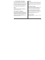
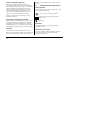
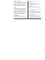
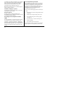
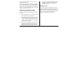
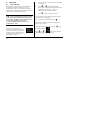
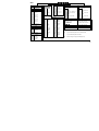
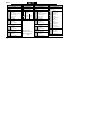
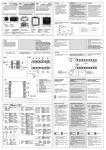
Process Indicator
3200i
User Guide
ENG
E U ROT H E R M
3200i Series Process Indicators and Alarm Units
Applies to Model numbers 3216i, 32h8i and 3204i
Contents
1.
What Instrument Do I Have? ............................................................................ 4
1.1
1.2
1.3
1.4
1.4.1
1.4.2
1.4.3
1.4.4
1.5
2.
Unpacking Your Indicator ...................................................................................................5
Dimensions Front Views.....................................................................................................5
Dimensions – Side and Top Views .......................................................................................6
Step 1: Installation.............................................................................................................7
Panel Mounting the Indicator.................................................................................................................................. 7
Panel Cut-out Sizes ..................................................................................................................................................... 7
Recommended minimum spacing of indicators. ............................................................................................... 8
To Remove the Indicator from its Sleeve ............................................................................................................ 8
Ordering Code ....................................................................................................................9
Step 2: Wiring.................................................................................................10
2.1
2.2
2.3
2.4
2.5
2.6
2.6.1
2.6.2
Terminal Layout 3216i Indicator........................................................................................10
Terminal Layout 32h8i Indicator........................................................................................11
Terminal Layout 3204i Indicators ......................................................................................12
Wire Sizes .........................................................................................................................13
Sensor Input (Measuring Input) ........................................................................................13
Outputs - 1/8 and 1/4 DIN Indicators.................................................................................14
Output 1 & Output 4 (AA Relay) .......................................................................................................................... 14
Output 3 Retransmission......................................................................................................................................... 15
Part number HA029005.
Issue 1.0
Sept-05.
Applies to software version 1.02
T
1
2.6.3
2.6.4
2.6.5
2.7
2.8
2.9
2.10
2.10.1
3.
Safety and EMC Information............................................................................19
3.1
4.
Installation Safety Requirements ...................................................................................... 20
Switch On ........................................................................................................24
4.1
4.1.1
4.2
4.3
4.3.1
4.3.2
4.3.3
4.4
4.4.1
5.
New Indicator................................................................................................................... 24
To Re-Enter Quick Code Mode............................................................................................................................. 28
Pre-Configured Controller or Subsequent Starts ............................................................... 28
Front panel layout............................................................................................................ 29
Alarm Indication ........................................................................................................................................................ 30
Out of Range Indication.......................................................................................................................................... 30
Sensor Break Indication........................................................................................................................................... 30
Operator Parameters in Level 1 ........................................................................................ 31
Tare Correction.......................................................................................................................................................... 32
Operator Level 2..............................................................................................33
5.1
5.1.1
5.2
2
Transmitter Supply.................................................................................................................................................... 15
Digital Inputs A and B .............................................................................................................................................. 15
Transducer Supply .................................................................................................................................................... 15
Indicator Power Supply .................................................................................................... 16
Example Wiring Diagram .................................................................................................. 16
Digital Communications (Optional) .................................................................................. 17
Additional Connections for 3216i...................................................................................... 18
Input/Output 1 & Output 2............................................................................................................................. 18
To Enter Level 2 ............................................................................................................... 33
To Return to Level 1................................................................................................................................................. 33
Level 2 Parameters ........................................................................................................... 34
5.3
5.3.1
5.3.2
5.3.3
5.3.4
5.3.5
5.3.6
5.4
5.4.1
5.4.2
Strain Gauge Calibration...................................................................................................38
Load Cell Calibration ................................................................................................................................................ 38
Comparison Calibration........................................................................................................................................... 39
Shunt Calibration....................................................................................................................................................... 39
Manual Calibration.................................................................................................................................................... 40
Automatic Calibration.............................................................................................................................................. 40
Calibration Using a Digital Input........................................................................................................................... 41
Recipes .............................................................................................................................42
To Store Values in a Recipe ................................................................................................................................... 42
To Load a Recipe ....................................................................................................................................................... 42
3
Installation and Basic Operation
1. What Instrument Do I Have?
Thank you for choosing this 3200i series Process
Indicator.
These are available as:Model
3216i
32h8i
32h8i/SG
3204i
4
Size
1/16
DIN
Inputs
Thermocouple
Pt100 RTD
V/mA/mV
1/8
DIN
Thermocouple
Pt100 RTD
V/mA/mV
2 Digital
1/8
DIN
1/4
DIN
Strain gauge
Outputs
1 – Relay, Logic,
Analogue or dig in
2 – Relay, or
Analogue
4 Changeover
relay
1 Changeover
relay
3 Retransmission
4. Changeover
relay
and Transmitter
PSU
As 32h8i
As 3216i
As 32h8i
Relay outputs can be configured for alarm and events
and analogue retransmission of process variable. 2wire Modbus digital communications is available in
all models.
The indicator may have been ordered to a hardware
code only or pre-configured using an optional ‘Quick
Start’ code. The label fitted to the side of the sleeve
shows the ordering code of the indicator. If the
Quick Code shows ***** the indicator will need to
be configured when it is first switched on.
This User Guide takes you through step by step
instructions to help you to install, wire, configure and
use the indicator. For features not covered in this
User Guide, a detailed Engineering Manual, Part No
HA029006, and other related handbooks can be
downloaded from www.eurotherm.co.uk.
1.1
Model 3216i
Unpacking Your Indicator
The following items are included in the box:
Latching
ears
•
Indicator mounted in its sleeve
•
Two panel retaining clips
•
AN IP65 sealing gasket mounted on the sleeve
•
Component packet containing a snubber for
each relay output and a 2.49Ω resistor for
current inputs (see section 2)
•
This User Guide
1.2
48mm
(1.89in)
48mm
(1.89in)
Model 3204i
Dimensions Front Views
Models 32h8i
Latching
ears
96mm
(3.78in)
48mm
(1.89in)
96mm (3.78in)
96mm (3.78in)
5
1.3
Dimensions – Side and Top Views
Side View –1/8 DIN & 1/4 DIN
Side View –1/16 DIN
2
48mm
(1.89in)
96mm
(3.78in)
1
3
1
1
d
3
2
2
90mm (3.54in)
Top View – 1/16 & 1/8 DIN
3
3
d
90mm (3.54in)
1 Latching ears
2 Panel retaining clip
3 IP65 Sealing Gasket
6
2
48mm
(1.89in)
1
d
90mm (3.54in)
d = Fascia depth 1.25mm (0.5in)
1.4
Step 1: Installation
3.
Insert the indicator through the cut-out
This indicator is intended for permanent installation,
for indoor use only, and enclosed in an electrical
panel
4.
Spring the panel retaining clips into place.
Secure the indicator in position by holding it
level and pushing both retaining clips forward.
Select a location which is subject to minimum
vibrations, the ambient temperature is within 0 and
55oC (32 - 131oF) and humidity 5 to 95% RH non
condensing.
5.
Peel off the protective cover from the display
The indicator can be mounted on a panel up to
15mm thick
1.4.2
Panel Cut-out Sizes
45 mm
Model
3216i
To ensure IP65 and NEMA 4 front sealing against
dust and water, mount on a non-textured surface.
Please read the safety information in section 3
before proceeding. The EMC Booklet part number
HA025464 gives further installation information.
1.4.1 Panel Mounting the Indicator
1. Prepare a cut-out in the mounting panel to the
size shown. If a number of instruments are to
be mounted in the same panel observe the
minimum spacing shown.
2.
- 0.0 + 0.6
1.77 inch
-0.00, +0.02
Model 32h8i
92 mm - 0.0 + 0.8
45 mm
3.62 inch -0.00, +0.03
- 0.0 + 0.6
1.77 inch
-0.00, +0.02
92 mm
- 0.0 + 0.8
3.62 inch
Model 3204i
-0.00, +0.03
Fit the IP65 sealing gasket behind the front
bezel of the indicator
7
1.4.3
Recommended minimum spacing of
indicators.
Applies to all Model sizes
10mm (0.4 inch)
38mm (1.5 inch)
(Not to scale)
8
1.4.4
To Remove the Indicator from its
Sleeve
The indicator can be unplugged from its sleeve by
easing the latching ears outwards and pulling it
forward out of the sleeve. When plugging it back
into its sleeve, ensure that the latching ears click
back into place to maintain the IP65 sealing.
1.5
1
Ordering Code
2
3
4
5
6
7
1. Model No.
3216i
1/16 DIN size
32h8i
1/8 DIN size (horizontal)
3204i
1/4 DIN size
2. Function
AL
Standard Unit
FM
FM Alarm Unit
DN
DIN 3440 alarm unit
SG
Strain Gauge Input 32h8i only
3. Power Supply
VL
24Vac/dc
VH
100–240Vac
4. Outputs
LRXX
RRXX
LDXX
DRXX
RXXX
(OP1, OP2, OP3)
OP1 Logic, OP2 Relay *
OP1 Relay, OP2 Relay *
OP1 Logic, OP2 Analogue *
OP1 Analogue, OP2 Relay *
OP1 Relay
(32h8i & 3204i only)
RXDX
OP1 Relay, OP3 Analogue
(32h8i & 3204i only)
* 3216i only
8
9
10
11
12
13
14
5. AA Relay (OP4)
R
Relay (Form C)
6. Options
XXX
Not fitted
(3216i only)
XXL
Digital input A (not
32h8i/SG, optional in 3216i)
2XL
RS232 & Digital input A
(includes Dig In A except
32h8i/SG)
4XL
RS485 & Digital input A
(includes Dig In A except
32h8i/SG)
7. Fascia colour/type
G
Green
S
Silver
8/9 Product/Manual Language
ENG
English
FRA
French
GER
German
ITA
Italian
SPA
Spanish
Quick Start Code (see section 4)
10. Input Adaptor
XX
None
V1
1-10Vdc
A1
mA Burden Resistor
(2.49Ω)
11. Warranty
Standard
XXXXX
Extended
WL005
12. Certificates
None
XXXXX
CERT1
Cert of
conformity
CERT2
5 Point Factory
calibration
13. Custom Label
XXXXX
None
14. Special and Accessories
XXXXXX
None
RES250
250Ω ; 0-5Vdc
OP
RES500
500Ω ; 0-10Vdc
OP
9
2. Step 2: Wiring
Key to Symbols used in the wiring diagrams
Logic (SSR drive) output
2.1
!
Relay output
Contact input
mA analogue output
Terminal Layout 3216i Indicator
Ensure that you have the correct supply for your indicator. Check order code of the indicator supplied
Digital input A
+
+
Input/Output 1
-
+
Output 2
-
Line Supply 100 to 240Vac 50/60Hz
OR Low Voltage Supply 24Vac/dc
1A
CT
AA
1B
C
AB
2A
LA
AC
2B
COM HD
VI
L
N
A(+) HE
B(-)
HF
V+
Part No SUB21/IV10
+
+
RS232
RS485
10
+
+
100KΩ
806Ω
2.49Ω
V-
Digital Communications
10V Potential divider
module
AA relay (OP4)
T/C Pt100
-
mA
mV
Sensor Input
10V
Input
-
2.2
Terminal Layout 32h8i Indicator
!
Ensure that you have the correct supply for your indicator. Check order code of the indicator supplied
Line Supply 100 to 240Vac 50/60Hz
OR
Low Voltage Supply 24Vac/dc
N
Input Connections for
32h8i/SG Indicator - Strain gauge input
Note: Dig in A is not available with this indicator
Signal |
-
+
24V
OP3 DC
Transmitter Retrans
Supply
V/mA
L
3D
3C
3B
-
+
-
Cal2
LC
LB
2B
2A
1B
1A
HD
AC
AB
AA
+
32h8i Indicator
Txdcr Supply
Cal1
3A
Output 1 (OP1)
Changeover
Relay
Dig in B
Ext-
Ext+
-
+
V-
-
T/C
Sensor Input
V+
VI
C
CT
HF
HE
+
Dig in A
Pt100
mV/V
LA
-
+
B(-) A(+) COM
Digital Comms
AA Relay
(OP4)
mA include the 2.49Ω load resistor
2.49Ω
11
2.3
!
Terminal Layout 3204i Indicators
Ensure that you have the correct supply for your indicator. Check order code of the indicator supplied
Output 1 (OP1)
Digital Input B
DC Retrans (OP3)
mA only
24V Transmitter Supply
1A
AA
1B
AB
AC
2B
HD
COM
LB
HE
A(+)
Digital
Communications
B(-)
RS232 or RS485
3204i Indicator
LC
HF
3A
+
CT
3B
-
C
3C
+
24V
-
LA
3D
Line Supply
100 to 240Vac 50/60Hz
OR
Low Voltage Supply
24Vac/dc
AA Relay (OP4)
2A
VI
L
V+
N
V-
Digital
input A
+
+
2.49Ω
-
T/C
Pt100
-
mA/mV
Sensor Input
12
+
100KΩ
10V Input
806Ω
- divider
10V Potential
module
Part No SUB21/IV10
2.4
Wire Sizes
The screw terminals accept wire sizes from 0.5 to 1.5
mm (16 to 22AWG). Hinged covers prevent hands or
metal making accidental contact with live wires. The
rear terminal screws should be tightened to 0.4Nm
(3.5lb in).
2.5
•
•
Sensor Input (Measuring Input)
Do not run input wires with power cables
When shielded cable is used, it should be
grounded at one point only
Any external components (such as zener barriers)
connected between sensor and input terminals
may cause errors in measurement due to
excessive and/or un-balanced line resistance, or
leakage currents.
Not isolated from the logic outputs & digital
inputs
•
•
Thermocouple Input
+
V+
Positive
V-
•
Negative
Use the correct compensating cable preferably
shielded.
RTD Input
•
VI
PRT
V+
PRT
V-
Lead compensation
The resistance of the three wires must be the
same. The line resistance may cause errors if it
exceeds 22Ω.
Linear mA, or mV Inputs
+
Positive
V+
V-
•
2.49Ω
Negative
-
For a mA input connect the 2.49Ω burden
resistor supplied between the V+ and Vterminals as shown. For mV omit this resistor.
Linear Voltage Inputs
+
0-10V
Input
V+
V-
-
An external potential
divider is required
for 3216i and 3204i
available as part no
SUB21/IV10.
13
2.6
Outputs - 1/8 and 1/4 DIN
Indicators
32h8i and 3204i indicators are supplied as standard
with two changeover relay outputs.
2.6.1
Output 1 & Output 4 (AA Relay)
Relay (Form C, changeover)
OP1
OP4
1A
AA
1B
AB
2A
AC
•
Isolated output 240Vac CATII
•
Contact rating:: 2A 264Vac resistive
•
Output functions: Alarm/Event
14
* General Notes about Relays and Inductive
Loads
High voltage transients may occur when switching
inductive loads such as some contactors or solenoid
valves. Through the internal contacts, these transients
may introduce disturbances which could affect the
performance of the instrument.
For this type of load it is recommended that a
‘snubber’ is connected across the normally open
contact of the relay switching the load. The snubber
recommended consists of a series connected
resistor/capacitor (typically 15nF/100Ω). A snubber
will also prolong the life of the relay contacts.
A snubber should also be connected across the output
terminal of a triac output to prevent false triggering
under line transient conditions.
WARNING
When the relay contact is open, or it is connected
to a high impedance load, it passes a current
(typically 0.6mA at 110Vac and 1.2mA at 240Vac).
You must ensure that this current will not hold on
low power electrical loads. If the load is of this
type the snubber should not be connected.
2.6.2
Output 3 Retransmission (Output 2
3216i)
•
OP3
•
3A
+
3B
-
•
•
Isolated output 240Vac CATII
2.6.4
Dig In A
Software configurable: 0-20mA
or 4-20mA plus 0-5V, 0-10V, 15V and 2-10V.
Max load resistance: 500Ω
Calibration accuracy: +(<0.25% of reading +
<50μA
Digital Inputs A and B
Digital input A is not available in 32h8i/SG and
optionally available on 3216i.
Dig In B
LA
LB
C
LC
•
Not isolated from the sensor input
•
Switching: 12Vdc at 40mA max
•
Output functions: PV retransmission.
•
Contact open > 500Ω. Contact closed < 200Ω
•
Output 2 non-isolated on 3216i
•
2.6.3
Transmitter Supply
A fixed 24Vdc supply is available to power an
external transducer (not 32i6i).
3C
+
3D
-
•
Isolated output 240Vac CATII
Input functions: Please refer to the list in the
quick codes.
2.6.5
Transducer Supply
In 32h8i/SG a 10Vdc supply is available as an
excitation voltage for a bridge type transducer
Ext1
+
•
Minimum load resistance 300Ω
Ext2
-
•
Isolated output 240Vac CATII
15
2.7
Indicator Power Supply
2.8
1.
Before connecting the indicator to the power
line, make sure that the line voltage corresponds
to the description on the identification label.
2.
Use copper conductors only.
3.
The power supply input is not fuse protected.
This should be provided externally.
4.
•
•
Fuse
N
L
3D
Signal |
RCAL
For 24V the polarity is not important.
3C
3B
3A
LC
LB
2B
2A
1B
1A
Txdcr Supply
- +
-
+
Cal1
Cal2 Ext-
Ext+
HF
HE
HD AC
AB AA
-
L
Line
24
24V
N
Neutral
24
24V
High voltage supply: 100 to 240Vac, -15%,
+10%, 50/60 Hz
Low voltage supply: 24Vac/dc, -15%, +10%
Recommended external fuse ratings are as
follows:For 24 V ac/dc, fuse type: T rated 2A 250V
For 100-240Vac, fuse type: T rated 2A 250V.
16
N
L
32h8i/SG Indicator
Power Supply
•
Example Wiring Diagram
This shows 32h8i connected to a strain gauge bridge.
+
Strain
Gauge
Safety requirements for permanently connected
equipment state:
• A switch or circuit breaker shall be included in
the building installation
• It shall be in close proximity to the equipment
and within easy reach of the operator
• It shall be marked as the disconnecting device for
the equipment.
Note: a single switch or circuit breaker can drive more
than one instrument.
2.9
Digital Communications (Optional)
RS485 Connections
Digital communications uses the Modbus protocol.
The interface may be ordered as RS232 or RS485 (2wire).
•
* RS232/RS485 2-wire
communications converter
eg Type KD485
Isolated 240Vac CATII.
RS232 Connections
Rx Tx
Com
Screen
Rx Tx
220Ω termination
resistor on last
controller in the line
Com
Daisy Chain to
further
controllers
Tx Rx Com
Local Ground
*
RxB/ RxA/
TxB TxA Com
Screen
HD
Common
HD
Common
HE
Rx A(+)
HE
Rx A(+)
HF
Tx B(-)
HF
Tx B(-)
220Ω termination
resistor
Twisted pairs
17
2.10
Additional Connections for 3216i
Connections for the 3216i indicator are similar to the
3216 controller.
DC Output
•
OP1/2
2.10.1 Input/Output 1 & Output 2
I/O1 may be configured as input or output.
1A
+
1B
-
•
Outputs can be logic (SSR drive), or relay, or mA dc.
•
Input is contact closure.
•
Relay Output (Form A, normally open)
•
•
OP1/2
1/2A
1/2B
Isolated output 240Vac CATII
Contact rating: 2A 264Vac
resistive
•
Output functions: Alarm or event
Logic (SSR drive) Output
•
OP1
1/2A
+
1/2B
-
•
18
•
•
Not isolated from the sensor
input
Output ON state: 12Vdc at
40mA max
Output OFF state: <300mV,
<100μA
Output functions: Alarm or event
•
Not isolated from the sensor input
Software configurable: 0-20mA
or 4-20mA.
Max load resistance: 500Ω
Calibration accuracy: 1%,
+100μA
Output functions: Retransmission.
Logic Contact Closure Input (OP1 only)
•
Not isolated from the sensor input
OP1
•
1A
•
1B
•
Switching: 12Vdc at 40mA max
Contact open > 500Ω. Contact
closed < 150Ω
Input functions: Please refer to
the list in the Quick Start codes.
3. Safety and EMC Information
GENERAL
This indicator is intended for industrial temperature
and process applications when it will meet the
requirements of the European Directives on Safety and
EMC. Use in other applications, or failure to observe
the installation instructions of this handbook may
impair safety or EMC. The installer must ensure the
safety and EMC of any particular installation.
The information contained in this manual is subject to
change without notice. While every effort has been
made to ensure the accuracy of the information, your
supplier shall not be held liable for errors contained
herein.
Safety
The packaging should contain an instrument mounted
in its sleeve, two mounting brackets for panel
installation and an Installation & Operating guide.
Certain ranges are supplied with an input adapter.
This indicator complies with the European Low
Voltage Directive 73/23/EEC, by the application of
the safety standard EN 61010.
Electromagnetic compatibility
This indicator conforms with the essential protection
requirements of the EMC Directive 89/336/EEC, by
the application of a Technical Construction File. This
instrument satisfies the general requirements of the
industrial environment defined in EN 61326. For
more information on product compliance refer to the
Technical Construction File.
Unpacking and storage
If on receipt, the packaging or the instrument is
damaged, do not install the product but contact your
supplier. If the instrument is to be stored before use,
protect from humidity and dust in an ambient
temperature range of -10oC to +70oC.
Service and repair
This indicator has no user serviceable parts. Contact
your supplier for repair.
19
Caution: Charged capacitors
Before removing an instrument from its sleeve,
disconnect the supply and wait at least two minutes to
allow capacitors to discharge. It may be convenient to
partially withdraw the instrument from the sleeve,
then pause before completing the removal. In any
case, avoid touching the exposed electronics of an
instrument when withdrawing it from the sleeve.
Failure to observe these precautions may cause
damage to components of the instrument or some
discomfort to the user.
Electrostatic discharge precautions
When the indicator is removed from its sleeve, some
of the exposed electronic components are vulnerable
to damage by electrostatic discharge from someone
handling the indicator. To avoid this, before handling
the unplugged controller discharge yourself to ground.
may be used to clean other exterior surfaces of the
product.
3.1
Installation Safety Requirements
Safety Symbols
Various symbols may be used on the indicator. They
have the following meaning:
!
Caution, (refer to accompanying documents)
Equipment protected throughout by DOUBLE
INSULATION
☺
Helpful hints
Personnel
Installation must only be carried out by suitably
qualified personnel
Cleaning
Enclosure of Live Parts
Do not use water or water based products to clean
labels or they will become illegible. Isopropyl alcohol
may be used to clean labels. A mild soap solution
To prevent hands or metal tools touching parts that
may be electrically live, the controller must be
enclosed in an enclosure.
20
Caution: Live sensors
The indicator is designed to operate if the temperature
sensor is connected directly to an electrical heating
element. However, you must ensure that service
personnel do not touch connections to these inputs
while they are live. With a live sensor, all cables,
connectors and switches for connecting the sensor
must be mains rated for use in 240Vac CATII.
Wiring
It is important to connect the indicator in accordance
with the wiring data given in this guide. Take
particular care not to connect AC supplies to the low
voltage sensor input or other low level inputs and
outputs. Only use copper conductors for connections
(except thermocouple inputs) and ensure that the
wiring of installations comply with all local wiring
regulations. For example in the UK use the latest
version of the IEE wiring regulations, (BS7671). In
the USA use NEC Class 1 wiring methods.
operator and marked as the disconnecting device for
the instrument.
Overcurrent protection
The power supply to the system should be fused
appropriately to protect the cabling to the units.
Voltage rating
The maximum continuous voltage applied between
any of the following terminals must not exceed
240Vac:
•
relay output to logic, dc or sensor connections;
•
any connection to ground.
The indicator must not be wired to a three phase
supply with an unearthed star connection. Under fault
conditions such a supply could rise above 240Vac
with respect to ground and the product would not be
safe.
Power Isolation
Conductive pollution
The installation must include a power isolating switch
or circuit breaker. This device should be in close
proximity to the indicator, within easy reach of the
Electrically conductive pollution must be excluded
from the cabinet in which the indicator is mounted.
For example, carbon dust is a form of electrically
conductive pollution. To secure a suitable atmosphere
21
in conditions of conductive pollution, fit an air filter to
the air intake of the cabinet. Where condensation is
likely, for example at low temperatures, include a
thermostatically controlled heater in the cabinet.
This product has been designed to conform to
BSEN61010 installation category II, pollution degree 2.
These are defined as follows:Installation Category II (CAT II)
For equipment on nominal 230V supply, the maximum
rated impulse voltage is 2500V.
Pollution Degree 2
Normally only non conductive pollution occurs.
Occasionally, however, a temporary conductivity caused
by condensation shall be expected.
Grounding of the temperature sensor
shield
In some installations it is common practice to replace
the temperature sensor while the controller is still
powered up. Under these conditions, as additional
protection against electric shock, we recommend that
the shield of the temperature sensor is grounded. Do
not rely on grounding through the framework of the
machine.
22
Over-temperature protection
When designing any control system it is essential to
consider what will happen if any part of the system
should fail. In temperature control applications the
primary danger is that the heating will remain
constantly on. Apart from spoiling the product, this
could damage any process machinery being
controlled, or even cause a fire.
Reasons why the heating might remain constantly on
include:
•
•
•
•
•
the temperature sensor becoming detached from
the process
thermocouple wiring becoming short circuit;
the controller failing with its heating output
constantly on
an external valve or contactor sticking in the
heating condition
the controller setpoint set too high.
Where damage or injury is possible, we recommend
fitting a separate over-temperature protection unit,
with an independent temperature sensor, which will
isolate the heating circuit.
This indicator can be used in addition to a controller
as an over temperature device. It is recommended that
the relay used to indicate the alarm condition should
be set to high alarm configured with sensor break and
inverse ‘Inv’ operation so that it relaxes to the alarm
condition when power is removed.
Installation requirements for EMC
To ensure compliance with the European EMC
directive certain installation precautions are necessary
as follows:
•
•
•
In this case to meet the conducted emissions
requirement, a suitable mains filter should be
installed. We recommend Schaffner types
FN321 and FN612.
Routing of wires
To minimise the pick-up of electrical noise, the low
voltage DC connections and the sensor input wiring
should be routed away from high-current power
cables. Where it is impractical to do this, use shielded
cables with the shield grounded at both ends. In
general keep cable lengths to a minimum.
For general guidance refer to Eurotherm Controls
EMC Installation Guide, HA025464.
When using relay outputs it may be necessary to
fit a filter suitable for suppressing the emissions.
The filter requirements will depend on the type
of load. For typical applications we recommend
Schaffner FN321 or FN612.
If the unit is used in table top equipment which is
plugged into a standard power socket, then it is
likely that compliance to the commercial and
light industrial emissions standard is required.
23
4. Switch On
4.1
1.
Press any button. The first character will change
to a flashing ‘-‘.
2.
Press
or
to change the flashing
character to the required code shown in the quick
New Indicator
If the indicator is new and has not previously been
configured it will start up showing the ‘Quick
Configuration’ codes. This is a built in tool which
enables you to configure the input type and range, the
output functions and the display format.
!
W
code tables –see next page. Note: An x
indicates that the option is not fitted.
3.
Incorrect configuration can result in damage
to the process and/or personal injury and must be
carried out by a competent person authorised to do
so. It is the responsibility of the person
commissioning the instrument to ensure the
configuration is correct
V
Press
°
to scroll to the next character.
☺ You cannot scroll to the next character until the
current character is configured.
☺
To return to the first character press
When all five characters have been configured the
display will go to Set 2.
When the last digit has been entered press
The quick code consists of two
‘SETS’ of five characters. The upper
section of the display shows the set
selected, the lower section shows the
five digits which make up the set.
Adjust these as follows:-.
24
.
°
again,
the display will show
V
W
Press
or
to
. The indicator will then
automatically go to the operator level.
SET 1
K C H C 0
Input Type
Display units
Decimal point
PV Colour
G
Strain gauge
Temperature
0
nnnnn (1)
32h8i only
32h8i only
C
oC
1
nnnn.n (1)
G
Green
N
PV only
F
oF
2
nnn.nn (1)
R
Red
A
First Alarm SP
K
K
3
nn.nnn (1)
C
Colour change on
X
None
4
n.nnnn (1)
P
%
Thermocouple
B
Type B
J
Type J
K
Type K
L
Type L
N
Type N
R
Type R
S
Type S
T
Type T
C
Custom C
RTD
P
Pt100
X
(2)
Home display
only
Alarm. Green to
red
1
PV + Alarm SP
R/W
Not applicable
2
PV + Alarm SP
R/O
32h8I/SG only:
0
Pa
D
L-m
1
mPa
E
%RH
2
Kpa
G
%O2
3
Bar
H
%CO2
4
mBar
J
%CP
5
PSI
L
V
Linear (all units)
6
Kg/cm2
M
Amp
M
0-80mV
7
mmWG
R
mA
2
0-20mA
8
inWG
T
mV
4
4-20mA
9
mmHG
U
Ohm
Linear 32h8i only
A
Torr
W
ppm
0
0-10Vdc
B
1
1-5Vdc
3
2-10Vdc
6
0-5Vdc
L-H
Y
RPM
Z
m-s
Set 1 is followed
Set this for the maximum
with R N G . H I
display range required
Then
RNG.Lo
display range required
Set 2 follows these
See next page
Set this for the minimum
parameters
(1)
Up to 2 decimal places on 3216i and 3204i
Up to 4 decimal places on 32h8i
(2)
Colour change on top part of display only
25
SET 2
H 3 L W V
OP1
X
Unconfigured
OP2/OP3
X
OP4 (AA Relay)
Unconfigured
X
Unconfigured
Digital input A and B
X
Unconfigured
Relay or Logic Output
Analogue Output
Alarm 1
PV Retransmission
Alarm 4
(Dig in A not available on
32h8i/SG)
H
High alarm
1
4-20mA
H
High alarm
W
L
Low alarm
2
0-20mA
L
Low alarm
R
Rate-of change - Rising
3
0-5Vdc
R
Rate-of change-Rising
N
New alarm flag
New alarm flag
Sensor break
1-5Vdc
N
O
4
Sensor break
Power fail
5
O
P
0-10Vdc
6
2-10Vdc
P
Power fail
With sensor Break
32h8i
only
With sensor Break
7
High alarm
7
High alarm
8
Low alarm
8
Low alarm
9
Rate-of change
9
Rate-of change
With power Fail
With power fail
A
High alarm
A
High alarm
B
Low alarm
B
Low alarm
C
Rate-of change
C
Rate-of change
With sensor
Break and power fail
E
High alarm
F
Low alarm
G
Rate-of change
26
For 3216i see
additional codes on
the following page
W
With sensor
Break and power fail
E
High alarm
F
Low alarm
G
Rate-of change
Alarm
acknowledge
K
Keylock
U
Remote up
button
D
Remote down
button
V
Recipe 2/1
J
Alarm Inhibit
M
Peak Reset
Y
Freeze PV
T
Tare correction
Z
Automatic zero
select
and span
calibration –
32h8I/SG only
Additional Quick Codes for 3216i - SET 2
1 K
OP2
OP1
Relay or Logic Output
Analogue Output
Alarm 2 (3216i only)
PV Retransmission
H
High alarm
(3216i only)
L
Low alarm
1
4-20mA
R
Rate-of change-Rising
2
0-20mA
N
New alarm flag
O
Sensor break
P
Power fail
With Sensor break
7
High alarm
8
Low alarm
9
Rate-of change
Logic Output
With power Fail
Digital input (3216i)
A
High alarm
W
Alarm acknowledge
B
Low alarm
K
Keylock
C
Rate-of change with sensor break and power fail
U
Remote up button
With Sensor break and power Fail
D
Remote down button
E
High alarm
V
Recipe 2/1 select
F
Low alarm
G
Rate-of change
27
4.1.1
To Re-Enter Quick Code Mode
If you need to re-enter the ‘Quick Configuration’
mode this can always be done as follows:1.
Power down the indicator
2.
Hold
button down and power up the
indicator again. Keep the button pressed until
you are requested to enter a passcode.
3.
V
4.2
Pre-Configured Controller or
Subsequent Starts
A brief start up sequence consists of a self test in
which all elements of the display are illuminated and
the software version number is shown.
The indicator will briefly show the quick codes
during start up, then proceed to Operator Level 1.
You will see the display shown below. It is called
the HOME display.
W
32h8i example
Enter a passcode using the
or
buttons. In a new indicator the passcode
defaults to 4. If an incorrect passcode is
entered you must repeat the whole procedure.
Process Value
Message Centre
Status Beacons
☺
Parameters may also be configured using a
deeper level of access. This is described in the
3200i Engineering Handbook Part No. HA029006.
This may be downloaded from
www.eurotherm.co.uk.
28
☺
If the Quick Codes do not appear during start up,
this means that the indicator has been configured in
a deeper level of access, see previous note. The
quick codes may then not be valid and are therefore
not shown.
4.3
Front panel layout
Operator Buttons:From any display - press to return to the
HOME display.
°
Press to select a new parameter. Hold down
to continuously scroll through parameters.
W
Press to change or decrease a value.
V
Beacons:ALM
Alarm active (Red)
OP1
Lit when output 1 is ON
OP2
This appears in 3216i only and is lit
when output 2 is ON
OP3
Lit when output 3 is configured to
retransmit the process value
OP4
Lit when output 4 is ON
REM
Communications active
Press to change or increase a value.
Message Centre
A scrolling message may appear in this section.
For example, if a high alarm is configured to
operate output 1, and a low alarm is configured to
operate output 4, the scrolling messages ‘ALARM
1 HIGH’ and ‘ALARM 4 LOW’ are shown
together with the beacons ‘ALM’, ‘OP1’ and
‘OP4’. ‘ALM’ flashes if the alarm has not been
acknowledged.
If the input sensor is broken ‘S.br’ appears in the
top display and the scrolling message ‘INPUT
SENSOR BROKEN appears in the message centre.
29
4.3.1
Alarm Indication
Up to four alarms can be configured. If any alarm
occurs, the red ALM beacon will flash. A scrolling
text message will describe the source of the alarm, for
example ALARM 1 HIGH. Any output attached to the
alarm will operate.
°
and
(Ack) together to
Press
acknowledge the alarm
If the alarm is still present the ALM beacon will light
continuously.
By default alarms are configured as non-latching, deenergised in alarm. If you require latched alarms,
please refer to the engineering handbook.
4.3.2
Out of Range Indication
If the input is too high HHHHH will be displayed
If the input is too low LLLLL will be displayed
30
4.3.3
Sensor Break Indication
An alarm condition (S.br) is indicated if the sensor
or the wiring between sensor and controller becomes
open circuit.
For a PRT input, sensor break is indicated if any one
of the three wires is broken.
For mA input sensor break will not be detected due to
the load resistor connected across the input terminals.
For Volts input sensor break may not be detected due
to the potential divider network connected across the
input terminals.
4.4
Operator Parameters in Level 1
Operator level 1 is designed for day to day operation
of the indicator and access to these parameters is not
protected by a pass code.
°
to step through the list of parameters. The
Press
mnemonic of the parameter is shown in the lower
display. After five seconds a scrolling text
description of the parameter appears.
Parameter
Mnemonic
HIGH
PEAK HIGH
LOW
PEAK LOW
tare
TARE FUNCTION
Linear inputs only
See also section 4.4.1.
A1
A2
A3
A4
(----)
(----)
(----)
(----)
The value of the parameter is shown in the upper
display. In level 1 the value is read only.
The parameters that appear depend upon the functions
configured. They are:-
Scrolling text and Description
ALARM 1 SETPOINT
ALARM 2 SETPOINT
ALARM 3 SETPOINT
ALARM 4 SETPOINT
Availability
This is the highest reading that the indicator has
recorded since switch on or since it was reset
This is the lowest reading that the indicator has recorded
since switch on or since it was reset
No tare correction
OFF
On
Select to automatically correct for tare
weight
Displayed if tare correction cannot be made
faiL
(----) shows the type of alarm configured. For
example HI, LO, ROC. This parameter sets the alarm
thresholds.
31
4.4.1 Tare Correction
Tare correction can be made in Operator Level 1. It is
used, for example, when it is required to weigh the
contents of a container but not the container itself.
The procedure is to place the empty container on the
weigh bridge and ‘zero’ the indicator. Since it is
likely that following containers will have different
tare weights the tare function is available in operator
level 1.
1.
With the empty container placed on the weigh
cell, repeatedly press
displayed.
V
or
W
°
until TARE is
to select On
2.
Press
3.
The weight of the container will automatically
be taken form the total weight.
4.
FaiL will be displayed if the tare function
fails, for example, if the weight is outside the
high and low limits or a sensor break condition
occurs. In this case correct the fault and repeat
the procedure.
32
Alternatively, a digital input may have been set by
selecting T in the quick codes (section 4.1) to provide
this function via an external source such as a switch
or pushbutton. In this case pressing the button will
have the same effect as selecting ‘On’ in 2 above.
5. Operator Level 2
6.
Press
Level 2 provides access to additional parameters. It is
protected by a security code.
5.1
To Enter Level 2
1.
From any display press and hold
2.
After a few seconds the
Release
Press
V
W
to
choose Lev 2 (Level 2)
5.
to enter the
If an incorrect code is entered the indicator
reverts to Level 1.
5.1.1
.
or
W
.
(If no button is pressed for 45 seconds the
display returns to the HOME display)
4.
or
pass code. Default = ‘2’
7.
display will show:3.
V
To Return to Level 1
1.
Press and hold
2.
Press
W
to select LEv 1
The indicator will return to the level 1 HOME
display. Note: A pass code is not required when
going from a higher level to a lower level.
After 2 seconds the
display will show:-
33
5.2
Level 2 Parameters
°
As in Level 1, press
to step through the list of
parameters. The mnemonic of the parameter is
shown in the message centre. After five seconds a
scrolling text description of the parameter appears.
The value of the parameter is shown in the upper
display. Press
V
or
W
repeatedly pressing
V
while holding down
.
To return to the HOME display at any time, press
.
The following table shows a list of parameters
available in Level 2.
Scrolling Display and description
Range
PRST
PEAK RESET Select On to reset the HIGH and LOW peak values. The
display automatically returns to OFF
OFF
ON
HIGH
PEAK HIGH This is the highest reading that the indicator has
recorded since switch on or since it was reset
Read only
LOW
PEAK LOW This is the lowest reading that the indicator has recorded
since switch on or since it was reset
Read only
tare
TARE FUNCTION
Linear inputs only
See also section 4.4.1.
34
°
to adjust this value.
If no key is pressed for 30 seconds the controller
returns to the HOME display.
Mnemonic
Backscroll is achieved when you are in this list by
OFF
On
faiL
No tare correction
Select to automatically correct for tare weight
Displayed if the tare correction cannot be made
Continued on next page W
Mnemonic
SG.TYP
Scrolling Display and description
STRAIN GAUGE CALIBRATION TYPE Select the calibration for the
type of sensor in use.
Range
SHnt
Strain gauge
bridge
Comparison
Load cell
ComP
CELL
OFF or 40.0 to 100.0%
LO.CAL
SHUNT CALIBRATION To set the high calibration point for a bridge
type strain gauge or pressure transducer.
STRAIN GAUGE LOW CAL 32h8i/SG only. See also section 5.3.
Hi.CAL
STRAIN GAUGE HIGH CAL 32h8i/SG only.
aut,sg
STRAIN GAUGE AUTO CAL
32h8i/SG only. See also section 5.3.5.
A1 (----)
A2 (----)
ALARM 1 SETPOINT
ALARM 2 SETPOINT
A3 (----)
ALARM 3 SETPOINT
A4 (----)
ALARM 4 SETPOINT
ADDR
ADDRESS Digital communications address for the instrument
1 to 254
HOME
HOME DISPLAY This configures the parameter which will be
displayed in the HOME display in normal operation
PV
Process variable
aLm
Alarm setpoint
SHUNT
See also section 5.3.
No
yes
Perform automatic strain gauge calibration
(----) shows the type of alarm
configured. For example
HIGH, LOW,
pv.aL
PV + Alarm SP
p.a.ro
PV + Alarm SP
read only
Continued on next page W
35
Mnemonic
Scrolling Display and description
Range
ID
CUSTOMER ID Customised instrument identification number
0 to 9999
REC.NO
CURRENT RECIPE NUMBER The recipe currently in use.
none
No recipe
See also section 5.4
1 - 5
1 to 5 selected
FaiL
Fail is shown if no
recipe is saved
RECIPE TO SAVE
none
No recipe to store
See also section 5.4
1 - 5
1 to 5
done
Recipe saved
STORE
Continued on next page W
36
Mnemonic
Scrolling Display and description
O
o
O
o
O
Kelvin
none
No units displayed
Perc
Percentage
pa
Pascals *
mpa
Mpascals *
kpa
Kpascals *
bar
Bar *
mbar
milli Bar *
psi
PSI *
kgcm
kg/sq cm *
mmwg
mm water gauge *
inwg
Inches water gauge *
mmhg
mm mercury *
torr
Torr *
L-H
Litres per hour *
L-m
Litres per minute *
p.rh
%Relative humidity*
p.O 2
% O2 *
p.CO2
% CO2 *
P.CP
% carbon potential*
VoLt
Volts *
Amp
Amps *
ma
milli amps *
mV
milli volts *
Ohm
Ohms *
ppm
Parts per million *
rpm
Revs per minute *
m-s
milli seconds *
SEC
Seconds *
min
Minutes *
hrs
Hours *
PH
Ph *
P.PH
% Ph *
mPH
Miles per hour *
mG
milli grams *
GrAm
Grams *
kG
Kilo grams *
C
* These
units only
appear in
32h8i
indicators
☺
Press
☺ Hold
Range
DISPLAY UNITS The display units are shown in the top right hand
corner of the display in normal operation. Units available are:-
UNITS
C
F
F
k
at any time to return immediately to the HOME screen at the top of the list.
°
down to continuously scroll through the above list
37
5.3
Strain Gauge Calibration
Different strain gauge transducers may be connected
to a 32h8i/SG indicator. It is generally necessary to
calibrate the instrument to the transducer in use. This
can be done in Operator Level 2 using any one of
three methods. These are:-
5.3.1 Load Cell Calibration
Connect a load cell as shown below:N
L
Fuse
N
SHUNT. This is so called since it refers to switching
a calibration resistor across one arm of a four wire
measurement bridge in a strain gauge transducer
(section 5.3.3).
The calibration for each of these can be made in Level
2 as described in the following sections.
To configure the different modes:In Level 2, press
V
38
or
W
°
Signal |
3B 3A LC
LB
2B 2A 1B 1A
Txdcr Supply
- +
Load Cell
-
+
CalI
Cal2
°
Ext-
Ext+
HF HE HD AC AB AA
1.
In Level 2, press
2.
Remove all weight from the load cell and press
V
or
W
to scroll to LO.CAL.
to select yes
3.
The indicator will show busy as it calibrates
the zero weight condition. pass or faiL will
be indicated when the low point calibration is
complete.
4.
Now add a weight which represents the full
scale span of the load cell
5.
Repeat the above to calibrate the high point –
HI.CAL.
to scroll to SG.TYP and press
to select CeLL, COmp or shnt
3D 3C
32h8i/SG Indicator
CELL. Here a load cell is connected directly to the
input terminals marked Signal + and – (section 5.3.1).
COMPARISON. The load cell is connected as
above but the calibration is compared with a reference
device or reference weight (section 5.3.2).
L
5.3.2 Comparison Calibration
Comparison calibration is most appropriate when
calibrating the indicator against a second reference
device.
5.3.3 Shunt Calibration
A bridge type strain gauge is connected as shown.
Depending on the type of gauge, RCAL may be
included internally or supplied as a separate item.
The load cell is connected as shown in the previous
example.
N
L
1.
In Level 2, press
press
V
or
W
°
Fuse
3D 3C
Signal |
3.
Press
or
to set the low value
calibration point as indicated by the reference
device. As soon as the value is entered the
indicator will show busy as it calibrates the
minimum weight condition. pass or faiL
will be indicated when the low point calibration
is complete.
W
Repeat the above steps to calibrate the high
point - HI.CAL
3B 3A LC
LB
2B 2A
1B 1A
Txdcr Supply
- +
RCAL
°
Press
to scroll to the next parameter C.ADJ (CALIBRATION ADJUST)
4.
L
32h8i/SG Indicator
to select yes
2.
V
N
to scroll to LO.CAL and
-
+
CalI
Cal2
Ext-
Ext+
HF HE HD AC AB AA
+
Strain
Gauge
The high (span) and low (zero) adjustment of the
transducer can be performed automatically or
manually. Manual allows the low point and high
point to be calibrated individually. Automatic
performs both low and high point calibration by the
selection of one parameter.
39
5.3.4 Manual Calibration
1.
Remove all pressure from the transducer to
establish a zero reference
2.
Press
°
to scroll to SHUNT and press
5.3.5 Automatic Calibration
1.
Remove all pressure from the transducer to
establish a zero reference
V
2.
In Level 2, press
3.
Press
W
or
to select the high calibration point for
the type of sensor in use. This will normally be
80.0%
3.
Press
or
4.
5.
40
W
°
to scroll to LO.CAL and press
V
to select yes
The indicator will show busy as it calibrates
the minimum weight condition. pass or
faiL will be indicated when the low point
calibration is complete.
or
W
to scroll to AUT.SG
to select yes
The indicator will automatically perform the
following sequence:a.
Disconnect the calibration resistor RCAL
b.
Calculate the low point calibration value by
continuously averaging two sets of 50
measurements of the input until stable readings
are obtained. Lo will be indicated during this
process.
c.
Connect the calibration resistor by closing a
contact between terminals VI and LA
d.
Calculate the high point calibration value by
continuously averaging two sets of 50
measurements of the input until stable readings
are obtained. Hi will be indicated during this
process.
°
Press
to scroll to HI.CAL and repeat the
above steps to calibrate the high point - HI.CAL
V
°
5.3.6 Calibration Using a Digital Input
A digital input may have been set by selecting Z in
the quick codes (section 4.1) to allow the transducer
to be calibrated automatically via an external source
such as a switch or pushbutton. In this case pressing
the button will have the same effect as selecting yes
in 3 above.
5.3.6.1 Fail
Fail will be displayed in any of the above calibration
procedures if the calibration is not possible. For
example, the input shows Sensor Break or is out of
range or the transducer or load cell is not connected
correctly. It is necessary to correct the fault and start
the procedure again.
41
5.4
5.4.2
Recipes
It is possible to store operating values in up to five
different recipes by taking a snapshot of the current
settings and storing these in a recipe number.
Examples, of typical operating parameters may be
alarm setpoint values. A particular recipe number
may then be recalled for a particular process.
5.4.1
To Load a Recipe
°
1.
In the list of parameters, press
rec.no
2.
Select a recipe number from 1 to 5 in which the
required settings have been stored. The values
will automatically loaded from the recipe. If no
values have been stored in that recipe, faiL
will be indicated.
to select
To Store Values in a Recipe
°
to select
1.
In the list of parameters, press
store
2.
Select a recipe number from 1 to 5 in which to
store the current settings. The indicator will
show done when the values are stored. All
previous values which may have been stored in
this recipe are overwritten.
This indicator meets the European directives
on safety and EMC
42
INTERNATIONAL SALES AND SERVICE
AUSTRALIA Sydney
Eurotherm Pty. Ltd.
Telephone (+61 2) 9838 0099
Fax (+61 2) 9838 9288
E-mail [email protected]
FRANCE Lyon
Eurotherm Automation SA
Telephone (+33 478) 664500
Fax (+33 478) 352490
E-mail [email protected]
IRELAND Dublin
Eurotherm Ireland Limited
Telephone (+353 1) 469180
Fax (+353 01) 4691300
E-mail [email protected]
SWEDEN Malmo
Eurotherm AB
Telephone (+46 40) 384500
Fax (+46 40) 384545
E-mail [email protected]
AUSTRIA Vienna
Eurotherm GmbH
Telephone (+43 1) 7987601
Fax (+43 1) 7987605
E-mail [email protected]
GERMANY Limburg
Eurotherm Deutschland GmbH
Telephone (+49 6431) 2980
Fax (+49 6431) 298119
E-mail [email protected]
ITALY Como
Eurotherm S.r.l
Telephone (+39 31) 975111
Fax (+39 31) 977512
Telex 380893 EUROTH I
E-mail [email protected]
SWITZERLAND Freienbach
Eurotherm Produkte (Schweiz) AG
Telephone (+41 55) 4154400
Fax (+41 55) 4154415
E-mail [email protected]
BELGIUM & LUXEMBURG Huy
Eurotherm S.A/N.V.
Telephone (+32) 85 274080
Fax (+32 ) 85 274081
E-mail [email protected]
HONG KONG & CHINA
Eurotherm Limited Aberdeen
Telephone (+85 2) 28733826
Fax (+85 2) 28700148
E-mail [email protected]
KOREA Seoul
Eurotherm Korea Limited
Telephone (+82 31) 2738507
Fax (+82 31) 2738508
E-mail [email protected]
UNITED KINGDOM Worthing
Eurotherm Limited
Telephone (+44 1903) 268500
Fax (+44 1903) 265982
E-mail [email protected]
Web www.eurotherm.co.uk
BRAZIL Campinas-SP
Eurotherm Ltda.
Telephone (+5519) 3707 5333
Fax (+5519) 3707 5345
E-mail [email protected]
Guangzhou Office
Telephone (+86 20) 8755 5936
Fax (+86 20) 8755 5831
NETHERLANDS Alphen a/d Ryn
Eurotherm B.V.
Telephone (+31 172) 411752
Fax (+31 172) 417260
E-mail [email protected]
DENMARK Copenhagen
Eurotherm Danmark A/S
Telephone (+45 70) 234670
Fax (+45 70) 234660
E-mail [email protected]
FINLAND Abo
Eurotherm Finland
Telephone (+358) 22506030
Fax (+358) 22503201
Beijing Office
Telephone (+86 10) 6762 0936
Fax (+86 10) 6762 0931
Shanghai Office
Telephone (+86 21) 6352 6406
Fax (+86 21) 6352 7351
INDIA Chennai
Eurotherm India Limited
Telephone (+9144) 24961129
Fax (+9144) 24961831
E-mail [email protected]
NORWAY Oslo
Eurotherm A/S
Telephone Oslo (+47 67) 592170
Fax (+47 67) 118301
E-mail [email protected]
ED43
SPAIN Madrid
Eurotherm España SA
Telephone (+34 91) 6616001
Fax (+34 91) 6619093
E-mail [email protected]
© Copyright Eurotherm Limited 2005
All rights are strictly reserved. No part of this document may be reproduced, modified, or transmitted in any form by any means, nor may it be stored in a retrieval system other than for the purpose
to act as an aid in operating the equipment to which the document relates, without the prior written
permission of Eurotherm limited.
Eurotherm Limited pursues a policy of continuous development and product improvement. The
specifications in this document may therefore be changed without notice. The information in this
document is given in good faith, but is intended for guidance only. Eurotherm Limited will accept no
responsibility for any losses arising from errors in this document.
HA029005/1 CN21593
U.S.A Leesburg VA
Eurotherm Inc.
Telephone (+1 703) 443 0000
Fax (+1 703) 669 1300
E-mail [email protected]
Web www.eurotherm.com
ENG
http://www.eurotherm.co.uk