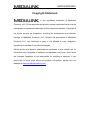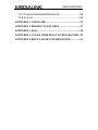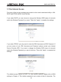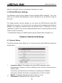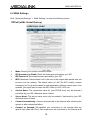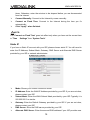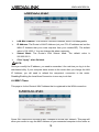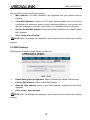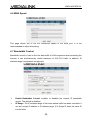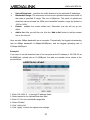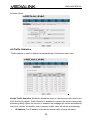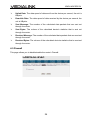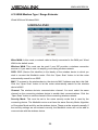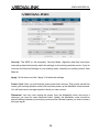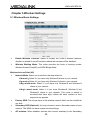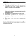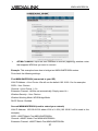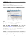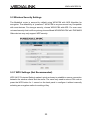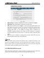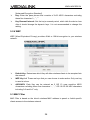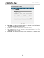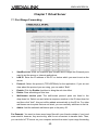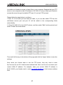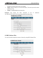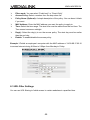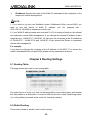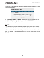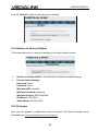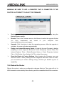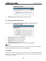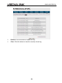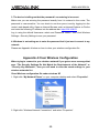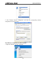
1
MWN-WAPR300N MWN-WAPR300N Copyright Statement is the registered trademark of Medialink Products, LLC. All the products and product names mentioned herein are the trademarks or registered trademarks of their respective holders. Copyright of the whole product as integration, including its accessories and software, belongs to Medialink Products, LLC. Without the permission of Medialink Products, LLC. any individual or party is not allowed to copy, plagiarize, reproduce or translate it into other languages. All the photos and product specifications mentioned in this manual are for references only. Upgrades of software and hardware may occur, and if there are changes, Medialink is not responsible for notifying in advance. If you would like to know more about our product information, please visit our website at www.medialinkproducts.com. MWN-WAPR300N Contents CHAPTER 1 PRODUCT INTRODUCTION ...................... 1 1.1 PACKAGE CONTENTS.................................................1 1.2 LED INDICATORS AND PORT DESCRIPTION .................1 CHAPTER 2 PRODUCT INSTALLATION ........................ 4 CHAPTER 3 HOW TO CONFIGURE YOUR COMPUTER’S ETHERNET (LAN) CONNECTION. ....... 5 3.1 HOW TO SET THE NETWORK CONFIGURATIONS...........5 3.2 LOG IN TO THE ROUTER ...........................................10 3.3 FAST INTERNET ACCESS ..........................................11 3.4 DEFAULT WIRELESS SETTINGS ................................12 CHAPTER 4 ADVANCED SETTINGS .............................. 12 4.1 SYSTEM STATUS .....................................................12 4.2 WAN SETTINGS ......................................................14 4.3 LAN SETTINGS .......................................................17 4.4 MAC CLONE ...........................................................18 4.5 DNS SETTINGS .......................................................19 4.6 WAN SPEED ...........................................................20 4.7 BANDWIDTH CONTROL .............................................20 4.8 TRAFFIC STATISTICS................................................23 4.9 FIREWALL ...............................................................24 4.10 WAN MEDIUM TYPE / RANGE EXTENDER ...............25 5.1 WIRELESS BASIC SETTINGS .....................................29 5.2 WIRELESS SECURITY SETTINGS ...............................33 5.2.1 WPS SETTINGS (NOT RECOMMENDED) .................33 5.2.2 WPA-PSK (WPA-PERSONAL)..............................34 MWN-WAPR300N 5.2.3 WPA2-PSK (WPA2-PERSONAL)..........................35 5.2.4 WEP ...................................................................36 5.3 MAC FILTER ...........................................................36 5.4 CONNECTION STATUS..............................................37 CHAPTER 6 DHCP SERVER ............................................. 38 6.1 DHCP SERVER .......................................................38 6.2 DHCP CLIENT LIST .................................................38 CHAPTER 7 VIRTUAL SERVER ...................................... 40 7.1 PORT RANGE FORWARDING .....................................40 7.2 DMZ SETTINGS .......................................................42 7.3 UPNP SETTINGS ....................................................42 CHAPTER 8 SECURITY SETTINGS ............................... 43 8.1 CLIENT FILTER SETTINGS ........................................43 8.2 MAC ADDRESS FILTER ............................................44 8.3 URL FILTER SETTINGS ............................................45 8.4 REMOTE WEB MANAGEMENT ...................................47 CHAPTER 9 ROUTING SETTINGS ................................. 48 9.1 ROUTING TABLE ......................................................48 9.2 STATIC ROUTING .....................................................48 CHAPTER 10 SYSTEM TOOLS ........................................ 50 10.1 TIME SETTINGS .....................................................50 10.2 DDNS ..................................................................50 10.3 BACKUP/RESTORE ................................................51 10.4 RESTORE TO FACTORY DEFAULT ...........................53 10.5 FIRMWARE ............................................................53 10.6 REBOOT THE ROUTER ...........................................54 MWN-WAPR300N 10.7 CHANGE USERNAME/PASSWORD ...........................55 10.8 SYSLOG ................................................................55 APPENDIX 1 GLOSSARY .................................................. 57 APPENDIX 2 PRODUCT FEATURES .............................. 57 APPENDIX 3 FAQ ............................................................... 58 APPENDIX 4 CLEAR WIRELESS CONFIGURATION . 59 APPENDIX 5 REGULATORY INFORMATION.............. 61 MWN-WAPR300N Chapter 1 Product Introduction Thank you for purchasing the Medialink Wireless 300N Router! This router is extremely easy to setup and easy to use. It supports 802.11n devices and is backwards compatible with 802.11b/g devices. The router can support various types simultaneously without slowing down your network. The Medialink wireless router includes a router, wireless AP, four-port Fast Ethernet (10/100) switch and firewall. It provides powerful online monitor functions and supports URL filter and MAC filter. With WDS function, it can repeat and amplify wireless signals from compatible Access Points so as to enlarge network coverage area. It supports UPnP and WMM to make your audio and video streaming smooth. With QoS function, it can efficiently distribute the data downloading from your ISP to the clients in your network. The router also comes equipped with WISP (Wireless WAN) function to access an ISP’s wireless hotspot or to create a new wireless network in addition to your existing wireless network by wirelessly connecting to any existing wireless router. 1.1 Package Contents Please verify the following items after you open the package: One Wireless N Broadband Router One Quick Installation Guide One Power Adapter One CD If any of the listed items are missing or damaged, please contact the Medialink reseller for immediate replacement. 1.2 LED Indicators and Port Description Panel and LED indicators show: LED indicator description on the front panel 1 MWN-WAPR300N Back panel ports 2 MWN-WAPR300N Back panel port description 3 MWN-WAPR300N Chapter 2 Product Installation 1. Please use only the included power adapter to power your router. (NOTE: Use of an unmatched power adapter could cause damage to this product). 2. Please connect the router’s LAN port to your computer with an Ethernet cable and connect your broadband line provided by your ISP to the router’s WAN port. 3. By default the Medialink router is set to use a Dynamic (DHCP) connection through the WAN port so unless you have a DSL Modem that requires the router to use a PPPoE type setup, then you will immediately have Internet access through the Medialink router. If you have a PPPoE setup that requires a DSL Username and Password to be entered into the router proceed to Step 4. 4. PPPoE Setup a. Open any Internet browser such as Internet Explorer or Firefox. b. In the address bar, type http://192.168.8.1 , then hit “Enter” on your keyboard. c. At the prompt enter the default Username (admin) and Password (admin). d. Select “PPPoE”, enter your DSL Username and DSL Password provided by your ISP and hit “Apply” 4 MWN-WAPR300N Chapter 3 How to configure your computer’s Ethernet (LAN) connection. (Please note that most computers are already configured correctly and do not require this step.) 3.1 How to Set the Network Configurations Network Configurations under Windows XP 1. Right click “My Network Places” on your computer desktop and select “Properties”. 2. Right click “Local Area Connection” and select “Properties”. 3. Select “Internet Protocol (TCP/IP)” and click “Properties”. 5 MWN-WAPR300N 4. Select “Obtain an IP address automatically” and “Obtain DNS server address automatically”. Click “OK” to save the configurations. Or if you want to specify a Static IP Address for your computer, select “Use the following IP address” and enter the IP address, Subnet mask, Default gateway as follows: IP Address: 192.168.8.XXX: (XXX is a number from 2~254) Subnet Mask: 255.255.255.0 Gateway: 192.168.8.1 6 MWN-WAPR300N DNS server: You should input the DNS server address provided by your ISP. Otherwise, you can enter 192.168.8.1. Click “OK” to save the configurations. Network Configurations under Windows 7 1. Click the network icon on the lower right corner of your computer desktop, and then click” Open Network and Sharing Center”. 2. Click “Change adapter settings” on the left side of the window. 7 MWN-WAPR300N 3. Right click “Local Area Connection” and select “Properties”. 4. Double click” Internet Protocol Version 4(TCP/IPv4)". 5. Select “Obtain an IP address automatically” and “Obtain DNS server address 8 MWN-WAPR300N automatically”. Click “OK” to save the configurations. Or if you want to specify a Static IP Address for your computer select “Use the following IP address” and enter the IP address, Subnet mask, Default gateway as follows: IP Address: 192.168.8.XXX: (XXX is a number from 2~254) Subnet Mask: 255.255.255.0 Gateway: 192.168.8.1 DNS server: You should input the DNS server address provided by your ISP. Otherwise, you can enter 192.168.8.1. Click “OK” to save the configurations. 9 MWN-WAPR300N 3.2 Log in to the Router 1. To access the Router’s Web-based Utility, launch a web browser such as Internet Explorer or Firefox and enter http://192.168.0.1 Press “Enter”. 2. You will be prompted to Login. The Default Username is “admin” and the Default Password is “admin” as well. Click Apply to enter the router’s GUI. 3. Note: To change the Login Credentials once you are logged in, go to “Advanced Settings” > “System Tools” > “Change Username/Password”. Once you have logged in, you will be directed to the Basic Settings Page where you can name your wireless network and set a password as well as configure your connection type. Click “Advanced Settings” to adjust any other settings within the router. 10 MWN-WAPR300N 3.3 Fast Internet Access Two kinds of fast access methods are provided on the router’s web-based utility or GUI: DHCP and PPPoE (aDSL Virtual Dial-Up). If you select DHCP, you can choose to change the Wireless SSID (name of network) and/or the Wireless Password if you want. Then click “Apply” to complete the settings. If you select PPPoE, you only need to enter the DSL Username and DSL Password. If you are unsure of your DSL Username and Password, please contact your Internet Service Provider (ISP). If you want to change the Wireless SSID (name of network) and/or the Wireless Password you can do that here. Then click “Apply” to complete the settings. The default access method is DHCP. For other access methods, please refer to WAN settings in Chapter 4. The wireless password must contain at least 8 characters. The 11 MWN-WAPR300N default is “password” and you can change it whenever you want. 3.4 Default Wireless Settings Your Medialink router is set by default to have a Wireless SSID “medialink”. This is the name of your network that will appear in a list to choose from on any device in range of the router. The default wireless security settings on your router are WPA-Personal using AES Algorithm for encryption. You can choose to you other security methods in the Advanced Settings. The password otherwise known as “Network Key” or “WPA Key” is set to “password” by default. This can be changed but please note it is case sensitive and must contain at least 8 characters. (For advanced setting or to disable wireless security, please refer to Chapter 5.2). Chapter 4 Advanced Settings 4.1 System Status The System Status screen allows you to view the router’s (blue) WAN port status and system status. Connection Status: This displays the router’s WAN connection status. Disconnected: indicates the router’s WAN port has not been connected with a network cable. Connecting: indicates the router’s WAN port is obtaining an IP address. Connected: indicates the Router is connected with your ISP or modem. WAN IP:IP address obtained from ISP, modem, or router. Subnet Mask: Obtained from ISP, modem, or router. 12 MWN-WAPR300N Gateway: Obtained from ISP, modem, or router. DNS Server: Obtained from ISP, modem, or router. Alternate DNS Server: Obtained from ISP, modem, or router. Connection Type: displays your current access method. LAN MAC Address:displays the Router’s LAN MAC Address. WAN MAC Address:displays the Router’s WAN MAC Address. System Time:displays the system’s updated time. Connected Client :displays the number of the connected computers whose IP addresses were obtained via DHCP server. Firmware Version:displays the Router’s firmware version. Hardware Version:displays the Router’s hardware version. 13 MWN-WAPR300N 4.2 WAN Settings Click “Advanced Settings” > “WAN Settings” to enter the following screen: PPPoE (aDSL Virtual Dial-up) Mode: Shows your current connection mode. ISP Username (or Email): Enter the Username provided by your ISP. ISP Password: Enter the password provided by your ISP. MTU: Maximum Transmission Unit is the size of the largest data packet that can be sent over the network. The default value is 1492. Do NOT modify it unless necessary, but if a specific website or web application software cannot open or be enabled, you might want to lower the MTU value to 1450, 1400, etc. Service Name: The connection name for your PPPoE must only be entered if instructed by your ISP. Otherwise leave it blank. Server Name: The server name must only be entered if instructed by your ISP. Otherwise leave it blank. Connect Automatically: Connect automatically to the Internet after rebooting the system or after connection failure. Connect on Demand: Re-establish your connection to the Internet after the specific time (Max Idle Time). Zero means you are connected to the Internet at all 14 MWN-WAPR300N times. Otherwise, enter the minutes to be elapsed before you are disconnected from the Internet. Connect Manually: Connect to the Internet by users manually. Connect on Fixed Time: Connect to the Internet during the time you fix automatically. Click “Apply” when finished. NOTE: The “Connect on Fixed Time” goes into effect only when you have set the current time in “Time Settings” from “System Tools”. Static IP If you have a Static IP account with your ISP, please choose static IP. You will need to enter the IP Address, Subnet Mask, Gateway, DNS Server and Alternate DNS Server provided by your ISP or network administrator. Mode: Shows your current connection mode. IP Address: Enter the WAN IP Address provided by your ISP. If you are not clear, please contact your ISP. Subnet Mask: Enter the WAN Subnet Mask provided by your ISP. Typically it is 255.255.255.0 or similar. Gateway: Enter the Default Gateway provided by your ISP. If you are not clear, DNS Server: Enter the DNS server provided by your ISP. Alternate DNS Server: Enter the second DNS address if your ISP provides one. please contact your ISP. 15 MWN-WAPR300N (optional) Click “Apply” when finished. Dynamic IP (Via DHCP) If your connection mode is Dynamic IP, it means every time you access the Internet, you will get a different IP Address. You do not need to enter any parameters in this mode, just Click “Apply” to apply the setting. PPTP Mode: Show your current connection mode. PPTP Server Address: The IP address or domain name of the destination server is used to specify the destination address for the PPTP connection. Username/Password: Used to validate identity when connecting to the PPTP server. Address Mode: Set the router’s IP address mode. You can select either “Dynamic” 16 MWN-WAPR300N or “Static”. If your ISP doesn’t provide the IP address, please select “Dynamic”. IP Address: Please enter the IP address provided by your ISP. Subnet mask: Please enter the subnet mask provided by your ISP, generally it is 255.255.255.0 or similar. Gateway: Please enter the gateway provided by your ISP. Click “Apply” when finished. L2TP Mode: Shows your current connection mode. L2TP Server Address: The IP address or domain name of the destination server is used to specify the destination address for the L2TP connection. Username/Password: Used to validate identity when connecting to the L2TP server. Address Mode: Set the router’s IP address mode. You can select either “Dynamic” or “Static”. If your ISP does not provide the IP address, please select “Dynamic”. IP address: Please enter the IP address provided by your ISP Subnet mask: Please enter the subnet mask provided by your ISP, generally it is 255.255.255.0 or similar. Gateway: Please enter the gateway provided by your ISP. Click “Apply” when finished. 4.3 LAN Settings Click “Advanced settings” > “LAN settings” to enter the following screen: 17 MWN-WAPR300N LAN MAC Address: The Router’s LAN MAC Address, which is unchangeable. IP Address: The Router’s LAN IP Address (not your PC’s IP address and not the WAN IP Address that your router acquires from your modem/ISP). The default value is 192.168.8.1. You can change this when necessary. Subnet Mask: The Router’s LAN Subnet Mask. The default value is 255.255.255.0 Click “Apply” when finished. NOTE: Once you modify the IP address, you need to remember it for next time you log in to the web-based utility. If your computer loses access to the router after you change the LAN IP Address, you will need to refresh the computer’s connection to the router. Disabling/Enabling the Local Area Connection is one way to do that. 4.4 MAC Clone This page is for the Router’s MAC Address that is registered to the WAN connection. Some ISPs require the end-user’s MAC Address to access their network. This page will allow your router to copy the MAC Address of your connected computer to the router so 18 MWN-WAPR300N that your ISP connection will work properly. MAC Address: The MAC Address to be registered with your Internet Service Provider. Clone MAC Address: Copies your PC’s MAC Address. Make sure you are using a computer that does work properly when connected directly to your modem and that your computer is currently connected to your Medialink router via Ethernet. Restore Default MAC Address: Restores the MAC Address to the default factory MAC Address. Click “Apply when finished. NOTE: After the settings are completed, reboot the device to activate the modified settings. 4.5 DNS Settings DNS stands for Domain Name System (or Service). Enable Manual DNS Assignment: Select to enable the manual DNS settings. Primary DNS Address: Enter a valid DNS address. Alternate DNS address: Enter a valid DNS address or leave this field blank. (optional) Click “Apply” when finished. NOTE: After the settings are completed, reboot the device to activate the modified settings. 19 MWN-WAPR300N 4.6 WAN Speed This page allows you to set the connection speed of the WAN port. It is not recommended to adjust this setting. 4.7 Bandwidth Control Bandwidth control is used to limit the data traffic of LAN computers when accessing the Internet. It can simultaneously control maximum of 254 PCs' traffic. In addition, IP address range configuration is supported. Enable Bandwidth Control: enables or disables the internal IP bandwidth control. The default is disabled. IP Range: The IP address range of the hosts whose traffic has been controlled. It can be a single IP address or IP address range. (For Single IP, enter the same IP in both fields. 20 MWN-WAPR300N Upload/Download: specifies the traffic direction for the selected IP addresses. Bandwidth Range: The maximum and minimum upload/download data traffic of the hosts in specified IP range. The unit is KByte/sec. The uplink of upload and download cannot exceed the WAN port bandwidth limitation range (by default is 1500 or 1492). Enable: enables the current edited rule. Otherwise, the rule will not go into effect. Add to list: After you edit the rule, click the “Add to list” button to add the current rule to the rule list. Here we take 2Mbps bandwidth as an example. Theoretically, the biggest downloading rate for 2Mbps bandwidth is 2Mbps=256KByte/s, and the biggest uploading rate is 512kbps=64KByte/s Example 1 If you want to set the download rate of the computer at the IP address of 192.168.8.2 as 80-90KByte/s, upload rate as 10-15KByte/s, first add one upload rule as shown in the picture below: 1. Enter 192.168.8.2 in the both IP address fields 2. Select upload in the Upload/Download field. 3. Enter 10-15 in the bandwidth range field 4. Select “Enable” 5. Click “Add to list” 6. Click “Apply” to finish the upload rule settings. 21 MWN-WAPR300N And then add a download rule as shown in the picture below. 1. Enter 192.168.8.2 in the both IP address fields 2. Select download in the Upload/Download field. 3. Enter 80-90 in the bandwidth range field 4. Select “Enable” 5. Click “Add to list” 6. Click “Apply” to finish the download rule settings. Example 2 Set the download rate of all computers within the range of 192.168.8.2--192.168.8.254 as 100-120KByte/s, and the upload rate as 20-30KByte/s, as shown in the picture below. Upload Rule: 22 MWN-WAPR300N Download Rule: 4.8 Traffic Statistics Traffic statistics is used to display the bandwidth that LAN devices have used. Enable Traffic Statistics: Enable the Medialink router to calculate the traffic used by the LAN devices. By default, Traffic Statistics is disabled to improve the router’s data packet processing ability. When this function is enabled, the webpage will refresh automatically every five minutes, meanwhile, each computer’s traffic value will refresh automatically. IP Address: The IP address of the device whose traffic is being calculated. 23 MWN-WAPR300N Uplink Rate: The data speed of data sent from the device per second, the unit is KByte/s. Downlink Rate: The data speed of data received by the device per second, the unit is KByte/s. Sent Message: The number of the calculated data packets that are sent out Sent Bytes: The volume of the calculated device’s statistics that is sent out Received Message: The number of the calculated data packets that are received Received Bytes: The volume of the calculated device’s statistics that is received through the router. through the router. through the router. through the router. 4.9 Firewall This page allows you to disable/enable the router’s Firewall. 24 MWN-WAPR300N 4.10 WAN Medium Type / Range Extender Wired WAN and Wireless WAN Wired WAN: In this mode, a network cable is directly connected to the WAN port. Wired WAN is the default mode. Wireless WAN: This mode can be used if your ISP provides a wireless connection service or if you want to use it to amplify your existing wireless network. SSID: SSID (Service Set Identifier) is the identity of the wireless device to which you wish to connect the Medialink router. Click the “Open Scan” button to let the router automatically search for an SSID. MAC: To connect to the wireless device, the device’s MAC Address must be in this field. Click the “Open Scan” button to let the router automatically search for the wireless device’s MAC. Channel: The wireless device’s communication channel. You must select the same channel as the connecting wireless device to enable their communications. Click the “Open Scan” button to see the channel of the connecting wireless network. Security Mode: This must be set to the same security mode that is used by the connecting device. The Medialink router must have the same Security Mode, Algorithm or Encryption Mode and Key as the wireless device. These must be entered manually. If the security settings are not entered correctly, the Medialink router will not be able to communicate with the wireless device. 25 MWN-WAPR300N How to use Wireless WAN to create a Wireless Bridge from your existing Wireless Router: LAN IP Address: First make sure the LAN IP Address of your Medialink router is on a different network segment than your connecting device. If the LAN IP Address of your existing wireless router or ISP’s wireless device is 192.168.0.1 then the LAN IP Address of your Medialink router must be 192.168.XXX.YYY where XXX does not equal “0”. YYY can be anything from 1~254. For example: If Existing Wireless Router’s LAN IP – 192.168.0.1 Then Medialink Wireless Router’s LAN IP – 192.168.8.1 will work. And Medialink Wireless Router’s LAN IP – 192.168.0.2 will not work. The LAN IP of your Medialink Router can be set in “Advanced Settings” > “LAN Settings” PLEASE NOTE: Since the WAN IP and LAN IP must be on different network segments, the devices that connect to your Existing Wireless Router will not be able to communicate to devices that connect to your Medialink router. Network printers, network attached storage and other shared devices will not be accessible across the two connections. DHCP: Make sure the DHCP Server of your Medialink router is Enabled. It is Enabled by default. Scan for Networks: To connect to the existing Wireless Router, click “Open Scan” to view the networks in your area as seen below: 26 MWN-WAPR300N Note: The Signal Strengh is displayed in dBm (-). It is not a percentage. Therefore the lowest number is the strongest signal. Select Your Network: Select the SSID that you wish to have your Medialink router connect to in order to extend the signal. The SSID and corresponding MAC Address and Channel will be added to the fields above automatically. If your network’s SSID is hidden you will have to manually enter it as seen below. Note that the channel and MAC have been automatically copied. 27 MWN-WAPR300N Security: The SSID (in this example), Security Mode, Algorithm and Key have been manually entered and exactly match the settings on the existing wireless router. If you do not know the Security Settings of your existing router, consult your existing router’s User Manual. Apply: Scroll down and click “Apply” to finalize the settings. Power Cycle: After you are finished, power down both devices. Then power up the first router (your existing wireless router) first and then power up the Medialink router second. You will now have a stronger signal to which you can connect. Placement: You may now unplug the power from the Medialink router and move it wherever you have an open electrical outlet. Ideally, the Medialink router should be placed halfway between your existing router and the ultimate location you wish to have a stronger signal. 28 MWN-WAPR300N Chapter 5 Wireless Settings 5.1 Wireless Basic Settings Enable Wireless Function: Select to enable the router’s wireless features; Wireless Working Mode: This router provides two kinds of working modes: deselect to disable it and all functions related with wireless will be disabled. Wireless Access Point(AP) and WDS Bridge Mode Wireless Access Point (AP) Network Mode: Select one mode from the drop-down list. 11b mode:Select it if you have only Wireless-B clients in your network. 11g mode:Select it if you have only Wireless-G clients in your network. 11b/g mixed mode: Select it if you have only Wireless-B and Wireless-G clients in your network. 11b/g/n mixed mode: Select it if you have Wireless-B, Wireless-G and Wireless-N clients in your network. This mode is default is recommended since b/g/n clients will each connect at their respective top speeds. Primary SSID: The unique name of the wireless network which can be modified at any time. Secondary SSID (Optional): You may choose to enter a Secondary name of your network. This SSID can have unique security settings. AP Isolation: When enabled, devices that connect wirelessly to the Secondary 29 MWN-WAPR300N SSID will be isolated from other devices that wirelessly connect to the Secondary SSID. AP Isolation is enabled by default. Broadcast (SSID): Select “Enable” to enable the router’s SSID to be detected by wireless devices. The default is enabled. If you disable it, the wireless devices must know the SSID for communication for it will be hidden. Channel: The channel currently used by the router. Select an effective channel (from 1 to 11 or AutoSelect) of the wireless network. The best channel is the least used channel by your neighbors. WMM Capable: Enables the router to enhance the transfer performance of the wirelessly transferred multimedia data (such as video or gaming). We recommend enabling this option at all times. APSD Capable: Used for auto power-saved service. The default is disabled. Channel Bandwidth: Select an appropriate channel bandwidth to enhance the wireless performance. Select 20/40M when the network has 11b/g and 11n wireless clients. Select 20M when the network has only non-11n wireless clients. Select 20/40M to promote its throughput when the wireless network is in 11b/g/n mode. Extension Channel: This allows devices to connect at n speeds using a 40M bandwidth. WDS Bridge Mode Settings WDS (Wireless Distribution System) is used to expand wireless coverage area. This can only be used with some wireless routers that support WDS and you must have ability to change the settings of both routers. 30 MWN-WAPR300N AP MAC Address: Input the MAC address of another (opposing) wireless router that supports WDS that you want to connect. Example: This example shows how to bridge two MWN-WAPR300N routers. First check the following settings: First MWN-WAPR300N (connected to your ISP) LAN IP Address: <Your Choice. We will use the default 192.168.8.1 for the example> SSID: <Your Choice> Channel: <Your Choice 1~11> Extension Channel: <Will be set automatically. Simply record it.> Wireless Security: <Your Choice> Wireless Working Mode: WDS Bridge Mode DHCP Server: Enabled Second MWN-WAPR300N (used to extend your network) LAN IP Address: 192.168.8.XXX where XXX is 2~254 (192.168.8.2 will be used in this example) SSID: <MUST Match First MWN-WAPR300N> Channel: <MUST Match First MWN-WAPR300N> Extension Channel: <MUST Match First MWN-WAPR300N> 31 MWN-WAPR300N Wireless Security: <MUST Match First MWN-WAPR300N> Wireless Working Mode: WDS Bridge Mode DHCP Server: Enabled (will be disabled as the last step of this configuration) Connect the Second MWN-WAPR300N to the First MWN-WAPR300N wirelessly: 1. Click “Open Scan” and select the First MWN-WAPR300N from the list and click the ”OK” button on the dialog box and then the corresponding wireless MAC address will be added to the AP MAC address field automatically. 2. Scroll down to the bottom of the page and click “Apply” after the MAC address is added. Connect the First MWN-WAPR300N to Second MWN-WAPR300N wirelessly: Repeat the steps above on the First MWN-WAPR300N to pair the two routers. Disable DHCP on the Second MWN-WAPR300N: Login to the Second MWN-WAPR300N at http://192.168.8.2 and disable the DHCP Server. Click “Apply”. Power Cycle: After you are finished, power down both devices. Then power up the First MWN-WAPR300N first and then power up the Second MWN-WAPR300N. You will now have a stronger signal to which you can connect. Placement: You may now unplug the power from the Second MWN-WAPR300N and move it wherever you have an open electrical outlet. Ideally, the Medialink router should be placed halfway between your existing router and the ultimate location you wish to have a stronger signal. 32 MWN-WAPR300N 5.2 Wireless Security Settings The Medialink router is secured by default using WPA-PSK with AES Algorithm for encryption. The default Key is “password”. WPA-PSK is very secure and very compatible with most devices. For stronger security, choose WPA2-PSK with AES. For even more universal security that is still very strong choose Mixed WPA/WPA2-PSK with TKIP&AES. Older devices may only support WEP security. 5.2.1 WPS Settings (Not Recommended) WPS (Wi-Fi Protected Setting) makes it quick and easy to establish a secure connection between the wireless clients and the router. The users only need to enter a PIN code or press the WPS button for 1 second on the back panel to configure it without manually selecting an encryption method or setting a Key. 33 MWN-WAPR300N WPS Settings: To enable or disable WPS function. The default is “Enable”. WPS Mode: PBC (Push-Button Configuration) and PIN code. PBC: Select the PBC and click “Apply”, or press and hold the WPS button on the back panel of the device for about one second. The WPS LED indicator will be flashing for 2 minutes, which means the WPS is enabled. During this time (flashing WPS LED), you can enable the wireless client to implement the WPS/PBC negotiation between them. When the WPS connection is completed, the LED indicator will be continuously lit. To add more clients, repeat the above steps.) PIN: If this option is enabled, you need to enter a wireless client’s PIN code in the field and keep the same code in the WPS client. NOTE: The use of WPS function requires the wireless client to support this function. If all devices do not support this function, then the devices that do not support it will not be able to connect. We do not recommend using WPS as it is not as secure as using other methods and creates compatibility issues in some networks. 5.2.2 WPA-PSK (WPA-Personal) WPA authentication guarantees to protect wireless users’ data and only the authorized network users will have access to the WLAN via the specified Network Key. 34 MWN-WAPR300N WPA Algorithms: Provides TKIP [Temporal Key Integrity Protocol] or AES [Advanced Encryption Standard]. Key: Enter the pass phrase that consists of 8-63 ASCII characters excluding these five characters \ , ' ; " Key Renewal Interval: Set the key’s renewal period, which tells the device how often it should change the dynamic keys. It is not recommended to change this setting. 5.2.3 WPA2-PSK (WPA2-Personal) WPA2 (Wi-Fi Protected Access version 2) provides higher security than and WPA (Wi-Fi Protected Access). WPA Algorithms: Provides TKIP [Temporal Key Integrity Protocol] or AES 35 MWN-WAPR300N [Advanced Encryption Standard]. Key: Enter the pass phrase that consists of 8-63 ASCII characters excluding Key Renewal Interval: Set the key’s renewal period, which tells the device how these five characters \ , ' ; " often it should change the dynamic keys. It is not recommended to change this setting. 5.2.4 WEP WEP (Wired Equivalent Privacy) provides 40-bit or 128-bit encryption to your wireless network. Default Key: Determines which Key will allow wireless clients to be accepted into WEP Key1~4: These are keys that you can choose to make active. Only one key the network. is used at a time. ASCII/HEX: Each Key can be entered as 5 OR 13 case sensitive ASCII characters excluding these five characters \ , ' ; " OR 10 OR 26 HEX characters including 0~9 and A~F only. 5.3 MAC Filter MAC Filter is based on the client’s wireless MAC address to permit or forbid specific clients access to the wireless network. 36 MWN-WAPR300N MAC Address Filter: “Permit” allows the clients in the list to be the only clients to be able to access the wireless network, “Forbid” prevents the clients in the list from accessing the wireless network but allows every one else. MAC Address: Input the MAC address of the each wireless client to implement the filter policy. Click “Add”. Repeat for additional clients. MAC Address list: Shows the added MAC addresses. You can add or delete them. Click “Apply” when finished. 5.4 Connection Status This screen shows each wireless client’s connection status, including MAC Address, Channel Bandwidth. Select SSID: Toggle between the Primary and Secondary SSID to see the clients MAC Address: Shows the MAC Addresses of the clients connected to the router. connected to each. Bandwidth: Shows the channel bandwidth of the currently connected wireless clients. 37 MWN-WAPR300N Chapter 6 DHCP Server 6.1 DHCP Server DHCP (Dynamic Host Control Protocol) is used to assign an IP address to the computers on the LAN/private network. When you enable the DHCP Server, the DHCP Server will allocate automatically an unused IP address from the IP address pool to the requesting computer when “Obtain an IP Address Automatically” is configured. You can specify the start and end address of the IP Address pool here: DHCP Server: Check “Enable” to enable DHCP server. IP Pool Start/End Address: Enter the range of IP addresses for the DHCP server Lease time: The valid time of the Dynamic IP address which is distributed to the to distribute. DHCP client’s host computer by your Medialink router’s DHCP server. During this time, the server will not distribute the IP address to any other connected device. 6.2 DHCP Client List DHCP client list displays user device’s IP Address, MAC address, host name and other information which are assigned by the DHCP server. You can manually enter the IP and MAC address and convert them to static assignment. 38 MWN-WAPR300N Host Name: The name of the device whose IP is allocated by the DHCP server. IP Address: Enter the IP address which needs static binding. This name is generated by the device itself. MAC Address: Enter the MAC address of the device you want to bind. Click “Add” to add the entry in the list. Lease time: The remaining time length of the corresponding IP address lease. 39 MWN-WAPR300N Chapter 7 Virtual Server 7.1 Port Range Forwarding Start/End Port: Enter the start/end port number which ranges the External ports used to set the server or Internet applications. LAN IP: Enter the IP address of the PC or device which you want to set as the server. Protocol: Select the protocol (TCP/UDP/Both) for the application. If you are not clear about the protocol you are using, you can select “Both”. Enable: Click the Enable checkbox to bring the rule into effect. Delete: Clear all settings of this item. Well-known service port: The well-known protocol ports are listed in the drop-down list. Select one and select a sequence number in the ID drop-down list and then click “Add”, this port will be added automatically to the ID list. For other well known service ports that are not listed, you can manually add them to the list. Add to: Add the selected well-known port to the policy ID. For Example: You want to share some large files with your friends outside of your local area network, however, they are too big, and it’s not convenient to transfer them. Then, you can build a FTP server on your computer and set the router’s port range forwarding 40 MWN-WAPR300N to enable your friends to access to these files on your computer. Suppose that your FTP server or your computer’s static IP address is 192.168.8.10, and you want your friends to access the server through the default FTP port: 21 and use TCP protocol. Please follow the steps below to configure. 1.Enter 21 in both start port and end port fields, or you can also select FTP from the well-known service port and port 21 will be added to the corresponding fields automatically. 2. Enter 192.168.8.10 in the LAN IP column, and then select “Both” as the protocol and select “Enable” as shown below: Then scroll all the way to the bottom of the page and click the “Apply” button to save the settings. Now, when your friends want to visit the FTP server, they only need to enter ftp://xxx.xxx.xxx.xxx:21 in their browser address field. Here, xxx.xxx.xxx.xxx means your router’s WAN IP address. For example, when your router’s WAN IP address is 24.65.128.52; your friends need to enter ftp://24.65.128.52:21 in the browser address field. 41 MWN-WAPR300N NOTE: If you set the service port of the virtual server as 80, you must set the Web management port on Remote Web Management screen to be any value except 80 such as 8080. Otherwise, there will be a conflict which will disable the virtual server. 7.2 DMZ Settings The DMZ Settings screen allows one local computer or device to be exposed to the Internet for use of a special-purpose service such as Gaming or VoIP. DMZ hosting forwards all ports to one device. DMZ Host IP Address: The IP address of the LAN device you want to set as the DMZ host. Enable: Check to enable the DMZ host. For example: Set your Game Console or VoIP device to the IP address 192.168.8.10 and then set that IP Address as the DMZ host to bypass the firewall of the router and allow for a smooth connection without interruption. NOTE: When the DMZ host is enabled, the firewall settings of the DMZ host will not function. 7.3 UPNP Settings UPnP (Universal Plug and Play): The LAN device can request the router to process some special port switching so as to enable the external host to access the resources of the internal host. 42 MWN-WAPR300N Enable UPnP: Click the checkbox to enable the UPnP. Chapter 8 Security Settings 8.1 Client Filter Settings You can enable Client Filter to control LAN computers’ access to some or all ports: Filter Mode: You can select either “Permit only” or “Forbid only”. Access Policy: Select a number from the drop-down list. Policy Name (Optional): A simple description of the policy. You can leave it blank if you want. Start/End IP: Enter the start/end IP address. Port: Enter the controlled TCP/UDP protocol port. You can specify a port or port range. For all ports enter 1 to 65535. Type: Select one protocol (TCP/UDP/Both) from the drop-down list. Time: Select the time range of client filter. The start time must be earlier than the 43 MWN-WAPR300N end time. The Time cannot cross over midnight. Day(s): Select the day(s) to run the access policy. The start day must be earlier Enable: To enable/disable the access policy. than the end day. Example1 Only Permit the Kids’ computers at the IP addresses 192.168.8.100~192.168.8.120 to access the Internet from 9am to 9pm. 8.2 MAC Address Filter You can limit certain computers’ access to Internet by using MAC Address Filter. 44 MWN-WAPR300N Filter mode: You can select “Forbid only” or “Permit Only”. Access Policy: Select a number from the drop-down list. Policy Name (Optional): A simple description of the policy. You can leave it blank if you want. MAC Address: Enter the MAC address you want the policy to apply to. Time: Select the time range. The start time must be earlier than the end time. The Time cannot crossover midnight. Day(s): Select the day(s) to run the access policy. The start day must be earlier than the end day. Enable: To enable/disable the access policy. Example 1 Forbid an employee’s computer with the MAC address of 14:35:8B:17:02:10 to access Internet during 8:00am to 5:00pm from Monday to Friday. 8.3 URL Filter Settings You can use URL filtering to forbid access to certain websites at a specified time. 45 MWN-WAPR300N Filter Mode: “Forbid only” is the only mode. Access Policy: Select a number from the drop-down list. Policy Name (Optional): A simple description of the policy. You can leave it blank if you want. Start/End IP: Enter the start/end IP address. URL Character String: Time: Select the time range. The start time must be earlier than the end time. The Specify the URL or keyword that you want to block. Time cannot crossover midnight. Day(s): Select the day(s) to run the access policy. The start day must be earlier than the end day. Enable: To enable/disable the access policy. Example1 Forbid all computers on LAN to access facebook.com during 8:00 to 18:00 from Monday to Friday. 46 MWN-WAPR300N NOTE: Enter only one domain name or keyword for each access policy. So, if you want to filter multiple domain names or keywords, you need to set multiple access policies. There is no way for any router to filter https:// addresses since they are encrypted so there is sometimes a way around this filtering process depending on the website and if the user knows this. 8.4 Remote Web Management This section instructs how to allow the network administrator to manage the Router remotely. Enable: Check to enable remote web management. Port: The management port open to outside access. The default value is 8080. 47 MWN-WAPR300N IP Address: Specify the range of the Public IP addresses of the computers on the Internet for remote management. NOTE: 1. If you want to log into your Medialink router’s Web-based Utility via port 8080, you need to use the format of WAN IP address: port (for example http : //220.135.211.56:8080) to implement remote login. 2. If your WAN IP address starts and ends with 0.0.0.0, it means all hosts on the Internet can implement remote Web management. If you change the Internet IP address to be a range like this: 124.88.97.17-124.88.97.19, then only the computers at the IP addresses of 124.88.97.17, 124.88.97.18 and 124.88.97.19 can access the Router to implement remote web management. For example: If you want to configure the computer at the IP address of 124.88.97.17 to access the router’s web-based utility via port 8080, please set the parameters as above. Chapter 9 Routing Settings 9.1 Routing Table This page shows the router’s core routing table. The main duty for a router is to look for the best path for every data packet, and transfer this data packet to a destination. In order to fulfill this function, many transferring paths, (i.e. routing table) are saved in the router, for use when needed. 9.2 Static Routing This screen is used to set the router’s static routing. 48 MWN-WAPR300N A static route is a pre-determined pathway that network information must travel to reach a specific host or network. Destination Network IP Address: The destination host or IP segment you visit. Subnet Mask: Enter the subnet mask, generally it is 255.255.255.0 Gateway: The entry IP address of the next router. NOTE: 1. The gateway must be at the same network segment as the router’s LAN IP Address. 2. If the destination IP address is one host’s address, then the subnet mask must be 255.255.255.255. 3. If the destination IP address is an IP segment, then it must match with the subnet mask. For example, if the destination IP is 10.0.0.0 then the subnet mask must be 255.0.0.0 49 MWN-WAPR300N Chapter 10 System Tools 10.1 Time Settings This section is to configure the router’s system time. You can set it manually or obtain the GMT time from the Internet. Time Zone: Select the time zone where you are operating the Router from the drop-down list. Customized time: Enter the time you wish to configure. This time is automatically acquired from your connected computer’s time settings. Use the Customized Time section to apply Daylight Savings Time. NOTE: When the Router is powered off, the time settings will be lost. The router will obtain the GMT time automatically the next time you access the Internet. Only when you connect to the Internet and obtain the GMT time or set the time on this screen, can the time settings in other functions (e.g. security settings) take effect. 10.2 DDNS DDNS (Dynamic Domain Name System) is used to assign a fixed host and domain name to a dynamic Internet IP address. Every time you access the Internet, the dynamic domain name software installed on your host will tell the ISP’S host server its dynamic IP address by sending messages. The server software is responsible for providing DNS service and implementing dynamic domain name resolution. 50 MWN-WAPR300N Main features: 1. Most ISP connections provide a dynamic IP address and the DDNS is used to capture the changeable IP address and match it to a fixed domain. Then users can have access to the Internet to communicate with others outside the network. 2. DDNS can help you to establish a virtual host in your home or company. DDNS: Click the radio button to enable or disable the DDNS service. Service provider: Select one from the drop-down list and click “Sign up” for registration. Username: Enter the username that you used to register from the DDNS provider Password: Enter the password that you used to register from the DDNS provider Domain name: Enter the effective registered domain name For example: Establish a Web server in the local host 192.168.8.10 and register in no-ip.com as follows: Username medialink Password password Domain Name medialink.no-ip.com After mapping the port in the virtual server, and setting account information in DDNS server, you can then access the web page by entering http://medialink.no-ip.com in any external PC’s browser address field. 10.3 Backup/Restore On this screen, you can back up the router’s current settings or restore previous settings. 51 MWN-WAPR300N Backup Settings: Click the Backup button to back up the router’s settings and select a path to save them. Click the “Save” button to save the configuration files. Restore Setting: Click the “Browse” button to select the backup files. 52 MWN-WAPR300N Click the “Restore” button to restore previous settings. 10.4 Restore to Factory Default This screen allows you to restore all settings to the factory default values. Restore to factory default: Click this button to restore to default settings. Factory default settings: Username: admin Password: admin Wireless SSID: medialink Wireless Password: password Wireless Security: WPA-PSK/AES IP Address: 192.168.8.1 Subnet Mask: 255.255.255.0 10.5 Firmware Here you can upgrade or rollback the router’s Firmware. The latest Firmware can be downloaded at www.medialinkproducts.com/support. 53 MWN-WAPR300N WARNING: BE SURE TO USE A COMPUTER THAT IS CONNECTED TO THE ROUTER VIA ETHERNET TO ADJUST THE FIRMWARE. Backup your settings: First Backup a copy of your router’s settings using the Backup/Restore section. Browse: Then in the Firmware screen, click Browse to select the upgrade file that you have downloaded and saved to your computer from www.medialinkproducts.com/support Upgrade: Click this button to start the upgrading process. After the upgrade is complete, the router will reboot automatically. Empty your Internet Browser’s Cache: In order for the new Firmware to display properly, you must empty the Browser’s Cache (Temporary Internet Files). For Internet Explorer: Tools > Delete Browser History > Check Temporary Internet Files > Click Delete. Once finished, hit F5 to refresh the screen. Reset the Router to Factory Settings: After changing the Firmware, you must reset the router to factory settings for the changes to take effect. After the reset, you can restore your router’s settings using a file that you backed up prior to upgrading. 10.6 Reboot the Router Reboot the router to make any configuration changes effective. The router will cut its WAN connection automatically after rebooting and then reestablish the WAN connection. 54 MWN-WAPR300N Reboot the router: Click this button to reboot the router. 10.7 Change Username/Password This section is to set a new password to better secure your router and network. Old Username: Enter the old username. New Username: Enter the new username. Old password: Enter the old password. New password: Enter a new password. Confirm new password: Re-enter to confirm the new password. NOTE: The default username and password is admin. To secure the router and your network, it is highly recommended that you change the initial password. 10.8 Syslog This section is to view the system log. You can view various conditions appearing after system start, and also check whether there’s an attack on the network. The log can record at most 150 entries. 55 MWN-WAPR300N Refresh: Click this button to update the log. Clear: Click this button to clear the currently shown log. 56 MWN-WAPR300N Appendix 1 Glossary Channel: A distinct frequency range within the 2.4 GHz wavelength. There are 11 available channels in North America ranging from 2412 MHz to 2462MHz. SSID: SSID (Service Set Identifier) is the network name shared by all devices in a wireless network. Your network’s SSID should be unique to your network and identical for all devices within the network. It is case-sensitive and must not exceed 20 characters. Make sure this setting is the same for all devices in your wireless network. WPA/WPA2 Encryption: A security protocol for wireless networks that builds on the basic foundations of WEP. It secures wireless data transmission by using a key similar to WEP, but the added strength of WPA is that the key changes dynamically. The changing key makes it much more difficult for a hacker to learn the key and gain access to the network. WPA2 is the second generation of WPA security and provides a stronger encryption mechanism through Advanced Encryption Standard (AES), which is a requirement for some government users. Appendix 2 Product Features Supports IEEE 802.11n, IEEE 802.11g, IEEE 802.11b, IEEE 802.3 and IEEE 802.3u standards. High gain omni-directional antenna, with strong signals and long transmission distance. Wireless transmission rate up to 150Mbps or 300 Mbps Provides one 10/100Mbps auto-negotiation Ethernet WAN port to connect to the Wide Area Network Provides four 10/100Mbps auto-negotiation Ethernet LAN ports to connect to the Local Area Network Supports Auto MDI/MDIX Supports xDSL/Cable MODEM, static and dynamic IP in community broadband networking as well as PPTP and L2TP. Includes router, wireless access point, four-port switch and firewall all in one SupportsWPA-PSK,WPA2-PSK,andWPA-PSK&WPA2-PSK mixed security modes Supports WPS button 57 MWN-WAPR300N Supports hidden SSID function and MAC Address-based access control Supports WMM to make your audio and video smoother Supports SNTP Supports UPnP and DDNS Supports WDS to extend wireless network Supports Wireless WAN and allows access to ISP’s wireless hotspots to share Internet access with multiple computers or the ability to extend an existing wireless network via a Wireless Bridge. Supports Virtual Server functions such as Port Forwarding and DMZ host. Provides Syslog to record the running status of the router Appendix 3 FAQ This section provides some solutions to the problems which may occur during the router’s installation or usage. The instructions below may help you deal with the problems. If website www.medialinkproducts.com your problem is not in the or list, send please visit an our E-mail to [email protected]. 1. Cannot log in to the Web-based Utility of the router after you enter the IP address in the address field? Step 1: Check if the router is working correctly, after the device is powered on for a few seconds, the SYS indicator on the front panel should light up. If it is not, please contact us. Step 2: Check that the network cables are connected correctly and the corresponding LED indicator lights up. Sometimes, the indicator lights up, but it does not mean it is functioning. Step 3: Run “Ping” command and check if it can ping the Router’s LAN IP address 192.168.8.1 (open “Command Prompt” and type “Ping 192.168.8.1” and then enter). If it is OK, please make sure your browser does not access the Internet by proxy server. If the ping fails, you can press the “RESET” button for 7 seconds to restore to default settings. And then repeat the ping operation. If it still does not work, please contact us. 2. I forgot the login password and cannot enter the Web-based Utility. Press the “RESET” button for 7 seconds to restore the Router to default settings. (UN: admin PW: admin) 58 MWN-WAPR300N 3. The device is telling me that the password I am entering is incorrect. Make sure you are entering the password exactly how it is entered in the router. The password is case-sensitive. You can check to see how yours is set by logging into the router’s web-based utility. Open an Internet Browser such as Internet Explorer or Firefox and enter the following IP address into the address bar: http://192.168.8.1 Log in using the default Username: admin and Password: admin. Then click Wireless Settings > Security Settings to see your password. 4. Windows is not asking me to enter the password but it just won’t connect to my network. Please see Appendix 4 below on how to clear your wireless configuration file. Appendix 4 Clear Wireless Configuration When trying to connect to your wireless network if you get an error message that says “The Security Settings Do Not Match the Requirements of the Network” or “Security Key Mismatch”, then you will need to clear the saved settings in your wireless networks list. Clear Wireless configuration file under windows XP 1. Right click “My Network Places” on your computer desktop and select “Properties”. 2. Right click “Wireless Network Connections” and select “Properties”. 59 MWN-WAPR300N 3. Click “Wireless Network Configuration” and clear the corresponding wireless configuration file as shown below. Clear Wireless configuration file under windows 7 1. Right click “Network” and click “Properties”. 60 MWN-WAPR300N 2. Click “Manage wireless networks” on the left side of the window. 3. Delete the corresponding configured file in the “Manage wireless networks”. Appendix 5 Regulatory Information EU Declaration or Declaration of Conformity Hereby, Medialink Products, LLC. declares that this Wireless Broadband Router is in compliance with the essential requirements and other relevant provisions of Directive 1999/5/EC. FCC Statement This equipment has been tested and found to comply with the limits for a Class B digital device, pursuant to part 15 of the FCC rules. These limits are designed to provide reasonable protection against harmful interference in a residential installation. This 61 MWN-WAPR300N equipment generates uses and can radiate radio frequency energy and, if not installed and used in accordance with the instructions, may cause harmful interference to radio communications. However, there is no guarantee that interference will not occur in a particular installation. If this equipment does cause harmful interference to radio or television reception, which can be determined by turning the equipment off and on, the user is encouraged to try to correct the interference by one or more of the following measures: -Reorient or relocate the receiving antenna. -Increase the separation between the equipment and receiver. -Connect the equipment into an outlet on a circuit different from that to which the receiver is connected. -Consult the dealer or an experienced radio/TV technician for help. To assure continued compliance, any changes or modifications not expressly approved by the party responsible for compliance could void the user’s authority to operate this equipment. (Example- use only shielded interface cables when connecting to computer or peripheral devices). “The antenna(s) used for this transmitter must not be co-located or operating in conjunction with any other antenna or transmitter.” FCC Radiation Exposure Statement This equipment complies with FCC radiation exposure limits set forth for an uncontrolled environment. This equipment should be installed and operated with the minimum distance of 20 cm. Operation is subject to the following two conditions: 1) This device may not cause interference, and 2) This device must accept any interference, including interference that may cause undesired operation of the device. Caution! The manufacturer is not responsible for any radio or TV interference caused by unauthorized modifications to this equipment. Such modifications could void the user authority to operate the equipment. 62