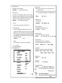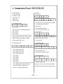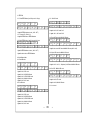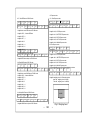
1
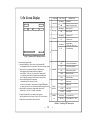
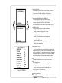
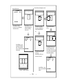
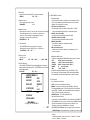
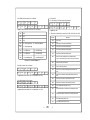
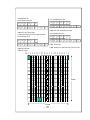
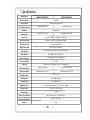
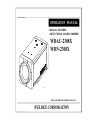
OPERATION MANUAL
Built-in x 23 ZOOM
AUTO FOCUS COLOR CAM ERA
WDAC-2308X
WDN-2308X
READ AND KEEP THIS OPERATION MANUAL
WELDEX CORPORATION
CAUTION
RISK OF ELECTRIC SHOCK
DO NOT OPEN
CAUTION:
TO REDUCE THE RISK OF ELECTRIC
SHOCK, DO NOT REMOVE COVER
(OR BACK). NO USER SERVICEABLE
PARTS INSIDE.
PREFER SERVICING TO QUALIFIED
SERVICE PERSONNEL.
Indicate a potentially hazardous situation which if not avoided,
may result in minor or moderate injury. It may also be used to
alert against unsafe practices.
Warning:
This equipment generates and uses radio frequency energy
and if not installed and used properly, I.e., in strict accordance
with the instruction manual, may cause harmful interference
to radio communications. It has been tested and found to comply
with the limits for a Class A computing device pursuant to Subpart
J of Part 15 of FCC Rules, which are designed to provide reasonable
protection against such interference when operated in a commercial
environment.
Warning:
TO PREVENT FIRE OR SHOCK HAZARD, DO NOT EXPOSE THIS
APPLIANCE TO RAIN OR MOISTURE.
CAUTION FOR SAFE OPERATION
1. Wate r and M oisture
To prevent fire or shock hazard, do not expose this camera
to rain or moisture.
8. Whe n operation is incorrect or a m alfunction is observed
While operating, if any abnormal condition (strange sound,
smell or smoke) or a malfunction (no pictures, etc.) is
observed, stop using the camera immediately, turn the
2. Servicing
Do not attempt to disassemble or repair by yourself.
You may be exposed to dangerous voltage or other hazards.
Note that all servicing is qualified service personnel.
Modifications not approved by manufacturer could
void the user's authority to operate the equipment.
pow er off, then contact your supplier.
9. Cleaning
Turn the pow er off and w ipe off the dirt w ith a dry soft
cloth. If it is extremely dirty, use furniture cleaner to w ipe it
off. To clean the lens, use a blow er or lens cleaning
tissue. (available from any camera dealer)
3. Pow e r Source s
To prevent electric shocks and risk of hazards, do NOT use
more than the specified pow er source.
10. Do not shoot any s ource of bright light.
If the objects contain very bright areas, bright vertical or
horizontal lines may appear on the screen. This is called
"smear" , a Phenomenon w hich often occurs w ith solid
- state pickups, and is not a malfunction.
4. Environm e nt
Do not install too w arm or too cold place. Recommended
operation temperature is betw een -5℃ and 60℃
11. Dam age Requiring s ervice
Unplug the camera from the pow er source and refer
servicing to qualified service personnel under the follow ing
5. Sunlight
Do not point the camera at the sun. CCD can be damaged.
condition:
a. If the power-supply cord or plug is damaged.
b. If the camera has been exposed to rain or water.
6. Heavy Shock and Vibration
Do not drop the camera or subject it to heavy shock of
vibration.
c. If liquid has been spilled, or objects hav e f allen into the camera.
d. If the camera does not operate normally by f ollowing the operating
instructions. Adjust only those controls that are cov ered by the
operating instructions as an improper adjustment of other controls
7. Install on an Unstable Place
Do not place or install this camera on an unstable place,
stand, tripod, bracket or table. That may cause serious injury
to people or damage to appliance.
-
2
may result in damage and will of ten require extensiv e work by a
qualif ied technician to restore the camera to its normal operation.
e. If the camera has been dropped or the cabinet has been damaged.
f . If the camera exhibits a distinct change in perf ormance.
-
CONTENTS
1. Features -------------------------------------------------------------- 4
2. Names & Functions ---------------------------------------------- 5
3. Installation----------------------------------------------------------- 6
4. Camera Control Methods------------------------------------------ 7
5. On Screen Display -------------------------------------------------- 9
6. Communication Protocol------------------------------------------ 14
7. Specifications-------------------------------------------------------- 26
8. Dimensions ---------------------------------------------------------- 28
Thank you for using this Auto Focus Zoom Color Camera. To get the best
efficiency, read carefully all instructions in this manual before use, and
keep this manual for reference. If you have any problems with this
camera, contact your supplier to service.
-
3
-
1. Features
Idea l Digita l Video Camera for Securi ty
AI / Fuzzy Control Circuit with DSP
The WDAC-2308X is a compact camera that of f ers easy sy stem
integration.Coming with the built-in zoom lens,the user can monitor
the scene f rom v ariable angle without the extra lens.
And,with the D.S.P. technology ,such intelligent controls as auto iris ,
auto back light compensation and auto white balance are possible to
realize clear detailed picture. Additionally ,through RS-232C/RS-485
linkage, remote Focus/Zoom operations are also possible,along with
manual control.All these f eatures including highly sensitiv e 1/4-inch
CCD make the ideal digital processing CCTV camera GC-655N/P
more ef f ectiv e surv eillance activ ities.
Adv anced DSP(Digital Signal Processor) technology automatically
adjusts operations such as Iris , White Balance f lexibly adapting to
env ironmental conditions.
Auto Iris : the iris is adjusted so that v isual output is kept at a
f ixed
lev el,ev en if brightness of the surrounding changes.
Auto White Balance : color adjustment according to the color
temperature of the light source illuminating the subject.
white balance can be obtained ev en with f luorescent
lights, halogen lamps or outdoor.
Built -in Optica l power zoom lens
M anua l Functi on Control( Key or Using RS-232C )
The WDAC-2308X with highly durable built-in zoom lens of f ers auto f ocus,
auto iris , and optical zoom f unctions enabling the user to monitor
a scene with clarity in any desired angle of v iew. With the x23 optical
zoom lens and up to x8 digital zoom processing,zoom ratio of the
GC-655N/P is expanded to x184.
High Resol ution & sensitivity SONY CCD
The chassis f eatures a highly sensitiv e 1/4-inch CCD pickup with
approximately 440,000) ef f ectiv e pixels
minimizing residual image and geometric distortion. All images are
reproduced with a high horizontal resolution of 470) TV lines f or f ine detail.
Remote Control through RS232C/RS485 Interfa ce
Remote control operations are possible through RS232C/RS485
interf ace f or Focus and Zoom (optical:up to x23,digital ~ x8) control.
In addition,the unit lets y ou command white balance and exposure
manually using RS232C/RS485 interf ace.
Compa ct si ze for va rious applica tions
The WDAC-2308X comes in the compact aluminum case enabling
the users put the unit into the other f orms of other outer case
( such as large dome camera or built in P/T/Z applications)
according to the particular purpose.
-
4
Following f unctions can be controlled manually
1) NEGA/POSI ;Negativ e/Positiv e
2) Digital Zoom ; x2 ~ x8 (Addition to Optical Zoom)
3) Iris Control ; Auto/Manual (Manual Iris lev el UP/DOWN)
4) AGC ; 8 dB ~ 38 dB Adjustable
5) White Balance ; Auto/Manual/Indoor/Outdoor/ATW
6) Manual White Balance ; R,B UP/DOWN
7) 64 Positions Zoom/Focus Preset
8) Power ON/OFF
9) Quick Zoom Control ; TELE/WIDE
10) Focus ; Auto/Manual/One shot ( PushAuto )
11) Manual Focus ; NEAR/FAR
12) On Screen Display Menu ; ALL Display / only Top / only Bottom
Display of f
13) 28 Steps Shutter Speed Control
14) Back Light Compensation ; ON/OFF/AUTO
15) Back Light lev el ; 00 ~ 80
16) Color ; ON/OFF
17) Mirror ; ON/OFF
18) Zoom Speed ; High/Medium/Low
19) Oneshot AF time ; 1 sec ~ 9 sec
20) AF sensitiv ity ; High/Low
21) Communication Baud-rate ; 1,200bps ~ 115,200bps
22) AE sensitiv ity ; High/Low
23) Minimum shooting distance ; 1cm ~ Inf inity ( ∞ )
24) simple priv acy area masking ; 6 areas
-
2. Names & Functions
FAR(-) BUTTON
S-VIDEO OUTPUT
This is the output terminal
for separate Y/C signal .
TELE(UP) BUTTON
NEAR(+) BUTTON
SVIDEO
VIDEO
MENU DISPLAY BUTTON
POWER
WIDE(DOWN) BUTTON
CONT
VIDEO OUTPUT
This is the output terminal
for composite video signal .
POWER INPUT TERMINAL
DC 12V input
( Please use a specified DC adaptor)
( Be careful its polarity )
CAMERA CONTROL CONNECTOR
POWER ON LAMP
This is the 14 pin connector for external
In power ON state , this LED is ON . camera controls .
( Refer to 4. CAMERA CONTROL METHODS )
-
5
-
3. Installation
3.1 Check all accessories with enclosed package .
-WDAC-2308X SET
- 14 PIN CONNECTION CABLE
- OPERATION MANUAL ( ENGLISH EDITION)
WDAC-2308X
14 PIN CONNECTION CABLE
OPERATION MANUAL
14P CABLE DESCRIPTION ;
1.
3.
5.
7.
9.
11.
13
KEY1 ( RED )
ZOOM ( GREEN )
MENU ( WHITE )
GND
( BLACK )
R+/NC ( BROWN )
T+/TD ( VIOLET )
EXT_VD ( WHITE )
2.
4.
6.
8.
10.
12.
14.
-
6
KEY2
FOCUS
COM
GND
R-/RD
T-/GND
GND
-
( YELLOW )
( BLUE )
( ORANGE )
( BLACK )
( PINK )
( GRAY )
( BLACK)
4. Camera Control Methods
4.1 Remote Control using for Hard wired connection ( Connector pin 3,4,5,6 )
Controller
TELE (-)
WIDE(+)
14P Cable
NEAR(+)
FAR (-)
MENU ON
4.2 Remote Control using for RS-232C connection ( Connector pin 10,11,12 )
Conne ct to Serial PORT
( COM 1 or COM 2 )
Serial Cable
14P Cable
Serial Cable
( 9 Pin D-Sub )
RD
2
TD
3
SG
5
14P Cable
1
0
1
1
1
2
RD ( TxD )
TD ( RxD )
GND
4
6
7
Conne ct internally
for com m unication
8
-
7
-
Re
la
y
Re
la
y
Re
la
y
14P Cable
3
ZOOM
4
FOCUS
5
MENU
6
COM
4.3 Remote Control using for RS-422/485 connection ( Connector pin 9,10,11,12 ) -------- OPTION
Connect to Serial PORT
(COM1 or COM2)
485 Conve rter
Se rial Cable
14P Cable
Serial Cable
( 9 Pin D-Sub )
RD
2
TD
3
SG
5
14P Cable
1
0
1
1
1
2
RD ( TxD )
TD ( RxD )
422
GND
4
6
7
485 Conve rter
Conne ct internally
for com m unication
T+
T-
8
R+
R-
14P Cable
9
1
0
1
1
1
2
R+
RT+
T-
485
485 Conve rter
TRxD+
TRxD-
-
8
-
14P Cable
9
1
0
1
1
1
2
R+
RT+
T-
5. On Screen Display
FUNCTION
①
,
Focus Mode
②
Back Light
③
Flickerless
④
Shutter Speed
<Fig5-1. Operating OSD display position>
5.1 How to display Operating OSD
a. Pressing the MENU key sof tly conf irm current Operating OSD.
It is disappeared about f iv e seconds later if there are no other key actions.
b. When it zoom in or out pressing TELE(up) or WIDE(down) key ,
⑤
whole Operating OSD is display ed and then disappeared.
Press NEAR(+) , FAR(-) key , only upper part of Operating OSD
( f or display ing camera mode ) is display ed and then disappeared.
(It is f or checking current whole camera mode and zoom position )
c. Ev en though Operating OSD is disappeared,
it keep display ing ID in lower part of screen.
In order to do not display ID, one method is to change EEPROM data
of Camera, the other is to use external communication through RS-232C.
⑥
d. Using RS-232C communication, change display position of ID;
Bottom Right -> Top Lef t -> Top Right -> Non display .
* If display Operating OSD is not needed by special purpose
like using external text ov erlay board, it can be OFF mode at all times
through external communication control as RS 232C.
⑦
OSD Format
Non display
MF
ZOOM
DISPLAY
CAMERA
ID
Manual / Push_Auto Mode
Non display
Back Light OFF
BL
Back Light ON
Non display
Flickerless OFF
FL
Flickerless ON
Non display
Normal Shutter
( NTSC:1/60 PAL :1/50 )
1 / 125
.
.
.
.
28 v ariable steps.
1 / 1 0, 0 0 0
ATW
WB MODE
DESCRIPTION
Auto Mode
Auto Trace White Balance
IN
Indoor Preset (3200°K)
OUT
Outdoor Preset (5400°K)
MWB
Manual WB mode
AWC
One Push mode
x23
Optical zoom
Dx50
Digital zoom
>> TELE
zoom TELE
<< WIDE
zoom WIDE
Non display
ID : 002
In case that ID is 0
In case that ID is 1 ~ 255
<Table5-1. Operating OSD description>
-
9
-
5.2 Display SETUP MENU
a. Press MENU key abov e 2 seconds so that SETUP MENU 1 is display ed
on the screen.
b. Select item of SETUP MENU using TELE(up) / WIDE(down) key .
c. NEAR(+) / FAR(-) key is used to increase / decrease data of selected item.
>>SETUP M ENU 1<<
.
.
.
.
.
.
NEXT M ENU
5.3 Mov e between SETUP MENU 1 and SETUP MENU 2
a. In order to change f rom SETUP MENU1 to SETUP MENU 2,
select NEXT MENU using TELE / WIDE key , and press NEAR / FAR key .
b. In order to change f rom SETUP MENU 2 to SETUP MENU1 ,
select PREV. MENU using TELE / WIDE key , and press NEAR / FAR key .
5.4 Quit SETUP MENU
a. Press the MENU key again. SETUP MENU is disappeared,
“SAVE?” or “QUIT?” is display ed at center of screen.
If there is no change of adjustment state of Camera,
“QUIT?” is showed, else “ SAVE?” is showed.
① “QUIT?” : quit SETUP MENU without sav ing changed v alue.
② “SAVE?” : quit SETUP MENU with sav ing changed v alue.
>>SETUP M ENU 2<<
.
.
.
.
.
.
PREV. M ENU
b. Press NEAR / FAR key to choose, and press the MENU key again.
whole SETUP MENU is quitted.
( If MENU key is not pressed and TELE / WIDE key is pressed,
SETUP MENU is appeared again. )
<Fig5-2. SETUP MENU change>
5.5 SETUP MENU 1 f unctions
① Backlight Compensation
: It is f or prev enting the center object too darken when the excessiv e light is
behind the center object. Press NEAR/ FAR key so that Backlight mode switch
ON/OFF. Set BACKLIGHT ON, then brighten the center object in the contrast to
the background light. Press NEAR/ FAR key in 2 sec, Backlight mode become
AUTO. When mode is AUTO, camera discriminate backlight condition and
compensate automatically . It can be changed backlight detection region of
screen .
According to changing backlight region its control is more smoothly and
becomes
proper brightness status.
BACKLIGHT
OFF → ON → (AUTO) → . . . .
<<SETUP MENU 1>>
① BACKLIGHT
OFF
② COLOR
ON
③ NEGATIVE
OFF
④ MIRROR
OFF
⑤ SHARPNESS
10
⑥ BRIGHTNESS
48
⑦ FLICKERLESS
OFF
⑧ MAX AGC
34dB
⑨ INITIAL SET
ON
② COLOR / Black&White Mode
: Use f or changing color and monochrome ( black & white )mode .
ON is Color mode, OFF is black&white mode.
COLOR
ON → OFF → . . . .
NEXT MENU
<Fig5-3. SETUP MENU 1 >
-
③ Positiv e / Negativ e Mode
10
-Positiv e and Negativ e mode. ON is Negativ e mode, OFF is Positiv e
: Use f or
mode namely general screen state.
NEGATIVE
OFF → ON → . . . .
ⅱ) Set BLC area in Backlight Auto mode
ⅰ) Set AUTO BLC mode
>> SETMENU 1 <<
BACKLIGHT
AUTO
.
.
.
.
.
1
1
5
5
1
?
5
NEXT MENU
Press MENU key , then
display ed backlight area
that can be modif y ing
( Ref er to B )
Press NEAR(+) or FAR(-)
key abov e 2 sec, then Backlight
mode becomes Auto.
If y ou want to change BLC
area , Mov e to desirable area
using TELE(up)/WIDE(down)
key .
The selected area becomes
blinking.
1
Press MENU key , then
display ed SETUP MENU1
again. At this time bellow
item ( color ON/Of f )becomes
blinking status.
>> SETMENU 1 <<
BACKLIGHT
AUTO
COLOR
ON
.
.
.
.
1
5
NEXT MENU
If y ou want to remov e current
selected area ,
Press NEAR(+)or FAR(-) key ,
current area is remov ed.
4
2
Press MENU key , then
PREV. to prev ious SETUP
MENU 1.
< Fig 5-4. Five BLC areas >
-
5
?
5
1
3
3
11
-
Press NEAR(+)or FAR(-) key ,
New area is selected, next
area is blinking. It can be selected
or remov ed all 5 areas with abov e
setting method repeatedly .
>> SETMENU 1 <<
BACKLIGHT
AUTO
COLOR
ON
.
.
.
.
NEXT MENU
④ Mirror Mode
: Mode ON is Mirror mode, Mode OFF is general screen state.
MIRROR
OFF → ON → . . . .
5.6 SETUP MENU 2 f unctions
⑤ Sharpness Control
: Use to change the contour of scene .
SHARPNESS
0 ~ 15
⑥ Brightness Control
: Adjust open and close lev el of iris in AI mode. The normal v alue is 48(50).
The smaller brightness v alue is, the darker it is, because iris is
closed more. On the contrary the bigger brightness v alue is,
the brighter it is, because iris is opened more.
BRIGHTNESS 0 ~ 99
⑦ Flickerless Mode
: Set FLICKERLESS ON to remov e the f licker of picture.
Shutter speed is f ixed as 1/100(NTSC) sec, 1/120(PAL) sec .
FLICKERLESS
OFF → ON → . . . .
⑧ Max AGC control
: Set AGC lev el.
MAX AGC
OFF → 8dB → 10dB → . . . . → 36dB → 38dB
⑨ INITIAL SET Mode
: Set the INITIAL SET Mode ON so that all changed data are returned to
shipping condition. Mode becomes OFF if SETUP MENU state is dif f erent
f rom shipping condition.
INITIAL SET
OFF → ON → . . . .
<<SETUP MENU 2>>
WB MODE
WB CONT
FOCUS SET
START ZOOM
END ZOOM
ATW
AUTO
ONESHOT
x1
x184
OFF
ID DISPLAY
SPECIAL MENU
PREV.
MENUMENU 2 >
< Fig 5-5.
SETUP
-
12
White Balance Mode
: Outer illumination condition is expressed by Color temperature ,Kelv in
(°K). It is White Balance that shows white as white in any illumination
conditions. It is composed of f iv e modes.
ATW ( Auto Trace White balance )
: do automatically under any condition in range 2,800°K ~ 8,000°K
It can be adjustable red and blue point of desired white position
INDOOR ( Indoor Preset WB )
: Use to set the preset illumination condition as 3200°K.
OUTDOOR ( Outdoor Preset WB )
: Use to set the preset illumination condition as 5400°K.
MANUAL ( Manual WB )
: Use to adjust to desired color temperature manually .
(0 ~ 99 decimal v alue )
AWC ( Auto White Control )
: Consider current illumination condition, do white balance by f orce
and lock as manual.
White Balance Mode Control
: It display s and changes White Balance Mode Control status of Camera.
ATW
AUTO ( It doesn’t need to adjust. )
INDOOR
3200°K ( It doesn’t need to adjust. )
OUTDOOR
5400°K ( It doesn’t need to adjust. )
MANUAL
50
( It can be adjust )
AWC
LOCK → PUSH → . . . .
(LOCK means Manual white balance status. Press NEAR(+) / FAR(-)
key continuously, LOCK mode becomes PUSH mode and white balance
acts automatically, and then white balance mode is locked as manual.)
Set Focus Mode
: It is composed of three modes.
AUTO : Use to f ocus automatically all the time.
MANUAL : Use to f ocus manually by pushing NEAR(+) / FAR(-)key .
Ev en though MANUAL mode, it will be f ocused in about 5 seconds af ter
zoom in(TELE) / out(WIDE), and return to MANUAL mode automatically .
This is f or f ocusing accurately af ter zooming.
ONESHOT(option) : It is similar to MANUAL mode.
But there are some dif f erence.
In case the f ocus mode is ONESHOT, it is f ocused whenev er ONESHOT
(AUTO/MANUAL key ) key is pushed. It will be returned to MANUAL mode
af ter the f ixed seconds ev en though can not be f ound best f ocus.
(Taking time is able to set in Special Menu. ) In this case
push ONESHOT(AUTO/MANUAL key ) key again, it will be in best f ocus.
-
PUSHAUTO(option) : While pushauto key is pushing, f ocus mode is auto.
☞ caution
1. According to Model, focus mode is Auto -> Manual -> Ones hot
or Auto -> Manual -> Pus hauto.
Set Start Zoom ratio
: Set boundary v alue of WIDE zooming.
START ZOOM
x 1 ~ x 22 ( in optical zoom region )
Set End Zoom ratio
: Set boundary v alue of TELE zooming. It can be set up to 184 x including
electronic zoom. ( in case the digital zoom limit is 8 times ) Since Start Zoom
and End Zoom ratio are set, simultaneously Camera mov es to setting zoom
times. So it can be enable to adjust in mov ing to desired position.
END ZOOM
x 23 ~ x 184 ( in digital zoom region )
☞ caution
1. End Zoom value mus t be lager than Start Zoom ratio.
Camera ID Display Mode
: Camera ID is indicating number assigned each Camera in case of
controlling many Cameras. It is f rom 0 to 255. But in case of 0, that is not
display ed on screen. It is alway s display ed ev en though whole Operating
OSD is disappeared on the screen. But it is possible to make non display
and to choose display position (BOTTOM RIGHT, TOP RIGHT, TOP LEFT)
by RS-232C communication.
ID DISPLAY
0 ~ 255
Special Menu (Option)
: Use f or Entering Special Menu.
5.7 SPECIAL MENU f unctions
O.S. AF TIME
MIN DIST
SHUTTER
BAUD RATE
AE SENS.
BLC LEVEL
HIGH
HIGH
5sec
50cm
NORMAL
9600bps
HIGH
24
ALL
OSD DISP.
RETURN
MENU MENU >
< Fig
5-6. SPECIAL
HIGH → LOW → ….
ZOOM Speed Control
: Set the zoom speed.
ZOOM SPEED
HIGH → MEDIUM → LOW
OneShot AF TIME control
: Set the Oneshot taking time in Focus mode.
O.S. AF TIME
1sec ~ 9 sec
Set Minimum Distance
: Set the minimum distance which can be f ocalized.
MIN DIST
1cm → 10cm → 50cm → 1m → 3m → 10m → infinity
Set BAUD RATE
: Set Baudrate to communicate by RS232C, RS485, RS232TTL.
BAUD RATE
9600bps → 1200bps → 2400bps → 4800bps →
19200bps → 38400bps → 76800bps → 115kbps
<<SPECIAL MENU>>
ZOOM SPEED
AF SENS.
Shutter Speed Control
: Set the Shutter Speed. (Ref er to. 17page Table 6-1)
At this time, Exposure mode becomes Shutter Fix mode.
SHUTTER
NORMAL→ 1/125 → … → 1/10000 → NORMAL
☞ caution
1. I n cas e of Camera I D FI X model, it cannot be s elected.
AF SENS.
AF SENS. Control
: High : Reaction of Auto Focus is f ast. It can be used when it shoot
objects mov ing f ast.
Low : Auto Focus is more stable. In f ast mov ing scene, AF doesn’t work
ev en though the scene is changed. It is f or stabilizing the scene.
-
13
AE SENS. Control
AE SENS.
HIGH → LOW
Set BLC Lev el
BLC LEVEL
24 ( 0 ~ 80 variable )
Set Operating OSD display
OSD DISP
ALL → NONE → TOP → BOTTOM → ALL → ...
ALL
: Display all operating OSD ( Focus mode& key action
status
, Zoom position , ID
Display )
NONE
: Clear all OSD except MENU page
TOP
: Display top position OSD only ( Focus mode , key action
status)
BOTTOM : Display bottom position OSD only ( Zoom position , ID )
-
6. Communication Protocol ( RS-232C,RS-422)
6.1 Serial Communication
6.1.1 Communication Format
A) Data length : 1by te (8bit)
B) Start bit / Stop bit : 1bit
C) Parity bit : none
D) Baud rate : 9600bps
6.2 Camera ID
6.2.1 Read Camera ID
byte2
byte3
byte4
0xC
C
dum
dum
dum
C/S
0xC
5
0xC
C
dum
dum
byte
5
dum
dum
dum
C/S
① 0xC5 means this protocol is to communicate between PC and CAMERA.
6.1.2 PC send 6by tes to Camera.
byte1
0xC5
byte5
② To communicate camera, read Camera ID f irst.
byte6
③ byte5 is Camera ID.
① by te1 : command 1
(which kind of protocol is this to communicate between A and B.)
② by te2 : command 2
③ by te3 : command 3
④ by te4 : command 4
⑤ by te5 : ID (To communicate cameras, each camera has its ID 0~255)
⑥ by te6 : checksum ( by te1 + by te2 + by te3 + by te4 + by te5 = C/S )
Command 2 is real acting code, and command 3, 4 are decided
according to command 2. ( Refer to 6.2~6.16 )
④ dum is dummy data that can be ignored.
6.1.3 Camera send 9by tes to PC.
6.2.3 Camera ID display ON/OFF
byte
1
byte2
byte
3
byte
4
byte5
byte
6
byte
7
byte8
⑤ C/S = 0xC5 + 0xCC + 0x00 + 0x00+ 0x00 = 0x91
6.2.2 Change Camera ID
0xC5
0xC5
byte3
0x78
byte
3
dum
dum
ID
dum
C/S
dum
dum
dum
C/S
dum
dum
C/S
dum
dum
C/S
① byte3 is New Camera ID which is to change .
② ID is current Camera ID.
byte
9
①
②
③
④
⑤
⑥
⑦
⑧
⑨
by te1 : command 1 receiv ed f rom PC
by te2 : command 2 receiv ed f rom PC
by te3 : command 3 receiv ed f rom PC
by te4 : command 4 receiv ed f rom PC
by te5 : send data 1
by te6 : send data 2
by te7 : send data 3
by te8 : send data 4
by te9 : checksum
( by te1 + by te2 + by te3 + by te4 + by te5 + by te6 + by te7 + by te8 = C/S )
-. byte1 ~ 4 must be same byte1 ~ 4 which PC send to Camera.
( If they are different , that means communication error. )
-. send data 1 ~ 4 are decided according to command 1~ 4.
-
0x78
14
0xC5
0xAA
0x6A
dum
ID
C/S
0xC5
0xAA
0x6A
dum
dum
dum
① Switch Camera ID display ON/OFF
② If the Camera ID is 0x00, then it’s not display ed.
6.2.4 Camera ID display position
0xC5
0x80
dum
dum
ID
C/S
0xC5
0x80
dum
dum
dum
dum
① Change camera ID display position.
② Bottom Right -> Top Lef t -> Top Right -> No display -> Bottom Right -> …
③ Whenev er this command is sent, position of ID is changed in upper order.
-
6.3 EEPROM
6.3.1 Read EEPROM data (f ront 2K by te out of 4K by te)
0xC5
0xF0
byte
3
dum
ID
0xC5
0xF0
byte
3
dum
byte5
6.4.3 Set AWC mode
dum
dum
dum
byte
3
byte
4
ID
0xC5
0x0F
byte
3
byte
4
dum
0xC5
0xAA
0x78
byte
4
dum
dum
dum
dum
C/S
0xC5
0xA
A
0x87
dum
ID
C/S
dum
dum
dum
0xC5
0xAA
0x87
dum
byte5
dum
dum
dum
C/S
C/S
① byte5 is the current HUE data at MANUAL WB mode (0x00 ~ 0x63).
0xC5
0xA
A
0x83
dum
ID
0xC5
0xAA
0x83
dum
byte5
6.4.5 Adjust HUE data at the MANUAL WB mode
C/S
dum
0xC5
0xA
A
0x65
byte
4
ID
0xC5
0xAA
0x65
byte
4
dum
0xC5
0xA
A
0x77
byte
4
ID
C/S
0xC5
0xAA
0x77
byte4
dum
dum
dum
dum
C/S
dum
C/S
6.4.6 Set ATW / MANUAL WB mode
0xC5
0xAA
byte3
dum
ID
C/S
0xC5
0xAA
byte
3
dum
dum
dum
① byte3 = 0x68 ; ATW mode
② byte3 = 0x69 ; MANUAL WB mode
③ It is not sav ed.
C/S
dum
dum
① byte4 = 0x00 ~ 0x63 ; 0 ~ 99(decimal) is HUE data at MANUAL WB mode
① byte5 = 0x00 ; ATW mode
② byte5 = 0x02 ; INDOOR WB mode
③ byte5 = 0x03 ; OUTDOOR WB mode
④ byte5 = 0x04 ; MANUAL WB mode
⑤ byte5 = 0x05 ; AWC mode
6.4.2 Set WB mode
;
;
;
;
;
C/S
C/S
6.4 White Balance Mode
6.4.1 Read WB mode
= 0x00
= 0x02
= 0x03
= 0x04
= 0x05
ID
6.4.4 Read HUE data at the MANUAL WB mode
② byte4 is data to write on EEPROM address
byte4
byte4
byte4
byte4
byte4
byte
4
② byte4 = 0x01 ; AWC mode “Push”
① byte3 is EEPROM address to write ( 0x00 ~ 0xFF )
①
②
③
④
⑤
0x78
① byte4 = 0x00 ; AWC mode “Lock”
6.3.2 Write EEPROM data ( f ront 2K by te out of 4K by te )
0x0F
0xA
A
C/S
① byte3 is EEPROM address to read ( 0x00 ~ 0xFF )
② ID : Camera’s ID ( Ref er 6.2.1)
③ byte5 is EEPROM data of EEPROM address
0xC5
0xC5
C/S
dum
dum
C/S
ATW mode
INDOOR WB mode
OUTDOOR WB mode
MANUAL WB mode
AWC mode
-
15
-
dum
dum
C/S
6.5 Exposure mode
6.5.1 Read Exposure mode
6.4.7 Read RED data at ATW WB mode
0xC5
0xA
A
0x85
dum
ID
0xC5
0xAA
0x85
dum
byte5
0xC5
C/S
dum
dum
dum
0xC5
C/S
① byte5 is the current RED data at ATW WB mode.
⑦ byte5 = 0x02 ; +2
0xC5
byte
4
ID
byte
4
dum
dum
dum
dum
C/S
0xC5
0xA
A
0x86
dum
ID
0xC5
0xAA
0x86
dum
byte5
0xC5
0xAA
0x76
byte
4
byte
4
0x60
byte
4
ID
byte4
dum
dum
dum
C/S
C/S
0xAA
0x60
dum
① byte4 = 0x00 ; AUTO Exposure mode
dum
dum
dum
⑤ byte4 = 0x04 ; MANUAL Exposure mode
6.5.3 Read Weighting v alue of Auto Exposure detection windows
C/S
0xC5
0xAA
0x6B
dum
ID
C/S
0xC5
0xAA
0x6B
dum
byte5
dum
① byte5 is weighting v alue of AE detection windows.
(upper 4bit ; weighting v alue f or WIND1.
lower 4bit ; weighting v alue f or WIND2.)
6.4.10 Adjust BLUE data at ATW WB mode
0x76
0xA
A
④ byte4 = 0x03 ; AGC FIX Exposure mode
C/S
is the current BLUE data at ATW WB mode.
= 0xFD ; -3 decimal BLUE data
= 0xFE ; -2
= 0xFF ; -1
= 0x00 ; 0
= 0x01 ; +1
= 0x02 ; +2
= 0x03 ; +3
0xA
A
C/S
③ byte4 = 0x02 ; IRIS FIX Exposure mode
6.4.9 Read BLUE data at ATW WB mode
0xC5
dum
② byte4 = 0x01 ; SHUTTER FIX Exposure mode
① byte4 is RED data to adjust at ATW WB mode.
byte5
byte5
byte5
byte5
byte5
byte5
byte5
byte5
dum
C/S
0xC5
6.4.8 Adjust RED data at ATW WB mode
①
②
③
④
⑤
⑥
⑦
⑧
dum
⑤ byte5 = 0x04 ; MANUAL Exposure mode
6.5.2 Set Exposure mode
⑥ byte5 = 0x01 ; +1
0x75
byte5
C/S
④ byte5 = 0x03 ; AGC FIX Exposure mode
⑤ byte5 = 0x00 ; 0
0xAA
0x00
ID
③ byte5 = 0x02 ; IRIS FIX Exposure mode
④ byte5 = 0xFF ; -1
0xC5
0x84
0x00
② byte5 = 0x01 ; SHUTTER FIX Exposure mode
③ byte5 = 0xFE ; -2
A
0xAA
0x84
① byte5 = 0x00 ; AUTO Exposure mode
② byte5 = 0xFD ; -3 decimal RED data
⑧ 0xC5
byte5 = 0xA
0x03 ; +3
0x75
0xA
A
WIND2
ID
C/S
dum
dum
dum
dum
WIND1
C/S
① byte4 is BLUE data to adjust at ATW WB mode.
< Fig 6-1. Weighting Area >
-
16
-
dum
dum
C/S
6.6.2 Read IRIS data
6.5.4 Adjust Weighting v alue of Auto Exposure detection windows
0xC5
0xA
A
0x6C
byte
4
ID
0xC5
0xAA
0x6C
byte4
dum
C/S
dum
dum
dum
C/S
0xC5
0xA
A
0x8B
dum
0xC5
0xAA
0x8B
dum
ID
C/S
byte5
dum
dum
dum
C/S
dum
dum
C/S
① byte5 is the current IRIS data of Camera lens.
① byte4 is weighting v alue of AE detection windows to adjust Camera.
(upper 4bit ; weighting v alue f or WIND1.
lower 4bit ; weighting v alue f or WIND2. Ref er to 6.5.3)
6.6.3 Adjust IRIS data
0xC5
0xAA
0x7C
byte4
ID
C/S
0xC5
0xAA
0x7C
byte4
dum
dum
6.5.5 Read AGC lev el
0xC5
0xA
A
0x8C
0x00
ID
0xC5
0xAA
0x8C
0x00
byte5
C/S
dum
dum
dum
① byte4 is IRIS data of Camera lens
(only in IRIS FIX or MANUAL Exposure mode : Ref er to 6.5.1 ).
C/S
① byte5 is the current AGC lev el of Camera.
② The range of IRIS data is 0x33 ~ 0xCD.
byte4
6.5.6 Adjust AGC lev el
0xC5
0xA
A
0x7D
0xC5
0xAA
0x7D
byte
4
byte
4
ID
dum
0x00
C/S
dum
dum
dum
C/S
① byte4 = 0x33 ~ 0xE8 ; AGC lev el of the Camera.
(only in AGC FIX or MANUAL Exposure mode : Ref er to 6.5.1).
6.5.7 Set Auto Exposure Sensitiv ity Mode
0xC5
0xA
A
0x5D
byte
4
0xC5
0xAA
0x5D
byte
4
ID
dum
C/S
dum
dum
dum
C/S
① byte4 = 0x00 ; High mode - Reaction is f ast.
② byte4 = 0x01 ; Low mode - Reaction is stable.
6.6 IRIS mode
6.6.1 Set AUTO / MANUAL Iris mode ( It is not sav ed. )
0xC5
0xA
A
byte
3
dum
0xC5
0xAA
byte
3
dum
ID
dum
C/S
dum
dum
dum
1/60
1/50
byte4
NTSC/PAL shutter speed
0x0E
1/1000
0x01
1/125
0x0F
1/1100
0x02
1/150
0x10
1/1200
0x03
1/200
0x11
1/1300
0x04
1/250
0x12
1/1500
0x05
1/300
0x13
1/1600
0x06
1/350
0x14
1/1800
0x07
1/400
0x15
1/2000
0x08
1/450
0x16
1/2500
0x09
1/500
0x17
1/3000
0x0A
1/600
0x18
1/3500
0x0B
1/700
0x19
1/4000
0x0C
1/800
0x1A
1/6000
0x0D
1/900
0x1B
1/10000
C/S
< Table 6-1. Shutter Speed >
① byte3 = 0x66 ; AUTO Iris mode
② byte3 = 0x67 ; MANUAL Iris mode
NTSC/PAL shutter speed
-
17
-
6.6.4 Read Shutter Speed ( Ref er to. Table 6-1)
0xC5
0xAA
0x8A
0x00
ID
C/S
0xC5
0xAA
0x8A
0x00
byte5
dum
6.7.4 Focus Manual Adjust (only in Manual Focus mode)
dum
dum
C/S
0xC5
0xA
A
byte
3
dum
ID
0xC5
0xAA
byte
3
dum
dum
C/S
dum
dum
dum
C/S
dum
dum
C/S
dum
dum
C/S
dum
dum
C/S
① byte3 = 0x5A ; FOCUS as FAR
② byte3 = 0X5B ; FOCUS as NEAR
③ byte3 = 0X5C ; FOCUS STOP
① byte5 is the current counter data to control Shutter Speed
6.6.5 Adjust Shutter Speed
6.7.5 Set Auto Focus Sensitiv ity Mode
0xC5
0xA
A
0x7B
byte
4
ID
0xC5
0xAA
0x7B
byte
4
dum
C/S
dum
dum
dum
0xC5
0xA
A
0x5E
byte
4
0xC5
0xAA
0x5E
byte
4
ID
C/S
C/S
① byte4 is shutter speed of the Camera
(only in SHUTTER FIX or MANUAL Exposure mode : Ref er to 6.5.1 ).
dum
dum
① byte4 = 0x00 ; High mode - Reaction is f ast.
② byte4 = 0x01 ; Low mode - Reaction is stable.
6.7.6 Adjust One-shot Auto Focus Time
6.7 Focus Mode
6.7.1 Set AUTO / MANUAL Focus mode ( It is not sav ed. )
0xC5
0xA
A
byte
3
dum
ID
0xC5
0xAA
byte
3
dum
dum
dum
dum
dum
0xA
A
0x73
0xC5
0xAA
0x73
byte
4
byte
4
ID
dum
0x58
byte
3
dum
0xC5
0x58
byte
3
dum
dum
ID
0xC5
0xAA
0x50
dum
dum
dum
0xC5
0x59
byte
3
dum
0xC5
0x59
byte
3
dum
ID
C/S
C/S
dum
dum
dum
dum
① byte3 = 0x00 - 1cm, 0x01 - 10cm, 0x02 - 50cm, 0x03 - 1m,
0x04 - 3m, 0x05 - 10m, 0x06 - Inf inity .
C/S
dum
dum
C/S
6.7.3 Sav e Focus mode
0x50
dum
6.7.7 Adjust Minimum Distance
② byte4 = 0x01 ; Push_Auto Focus mode
0xA
A
C/S
① byte3 = 0x01 ~ 0x09 ; The unit is seconds.
① byte4 = 0x00 ; AUTO/MANUAL Focus mode
0xC5
ID
C/S
① byte3 = 0x58 ; AUTO Focus mode
② byte3 = 0x59 ; MANUAL Focus
mode
6.7.2 Set Focus mode
0xC5
0xC5
C/S
dum
dum
C/S
① Whether current Focus mode is Auto or Manual, it is sav ed on EEPROM.
-
18
-
6.8 PRESET
6.8.1 Read Lens Zoom Position & Digital Zoom data
0xC5
0x36
dum
dum
ID
C/S
0xC5
0x36
dum
dum
byte5
byte
6
6.8.3.2 Read Zoom Position, Focus Position , D.zoom Data on EEPROM
( rear 2K by te out of 4K by te)
byte
7
dum
0xC5
0xF1
byte
3
dum
ID
C/S
0xC5
0xF1
byte
3
dum
byte5
dum
C/S
① byte5 = upper by te of Lens Zoom Position.
dum
dum
C/S
① by te3 is address to read preset data.
② byte6 = lower by te of Lens Zoom Position.
② by te5 is partial data of preset data.
③ byte7 = Digital Zoom data
6.8.2 Read Lens Focus Position
③ One preset data is composed of 4 data. (Ref er to 6.8.3.1)
6.8.3.3 Store PRESET position
0xC5
0x37
dum
dum
ID
C/S
0xC5
0x37
dum
dum
byte5
byte
6
( Zoom position, Focus position, D.zoom data of camera lens)
dum
dum
C/S
① byte5 = upper by te of Lens Focus Position.
② byte6 = lower by te of Lens Focus Position.
0xC5
0x79
byte
3
dum
ID
0xC5
0x79
byte
3
dum
dum
C/S
dum
dum
dum
C/S
① Read current Zoom position data, Focus position data, D.zoom data.
6.8.3 Internal Preset – It is to use EEPROM.
② Write data of ① on EEPROM rear 2K.
6.8.3.1 Write Zoom Position, Focus Position , D.zoom Data on
EEPROM ( rear 2K by te out of 4K by te)
0xC5
0x1F
byte3
byte4
ID
C/S
0xC5
0x1F
byte
3
byte
4
dum
byte
6
dum
③ The address of EEPROM to write is indicated by by te3, “index”.
6.8.3.4 Mov e to Preset Position with Non Tracking
dum
C/S
① byte3 is EEPROM address to write ( 0x00 ~ 0xFF )
0xC5
0x7A
byte
3
dum
ID
0xC5
0x7A
byte
3
dum
dum
C/S
dum
dum
dum
C/S
① by te3 is index of preset position, index is f rom 0 to 7 in numerical order.
② byte4 is partial data to write on EEPROM.
③ You hav e to write 4by te to sav e one preset data (Ref er to ④~⑧ example)
④ lower by te of lens zoom position (preset data 0) on address 0x00
② According to preset data on EEPROM, lens mov e to sav ing zoom position,
f ocus position, d.zoom data.
③ At this time lens mov e to the position without zoom tracking.
6.8.3.5 Slow Auto zoom tracking mov ing control
⑤ lower by te of lens f ocus position (preset data 0) on address 0x01
⑥ low 4bit of upper by te of lens zoom position (preset data 0)
on address 0x02 upper 4bit
⑦ low 4 bit of upper by te of lens f ocus position (preset data 0)
on address 0x02 lower 4bit
0xC5
0x7D
byte
3
dum
ID
0xC5
0x7D
byte
3
dum
dum
C/S
dum
dum
dum
C/S
⑧ digital zoom data (preset data 0) on address 0x03
① by te3 is index of preset position, index is f rom 0 to 63 in numerical order.
⑨ You can sav e 64 preset data. ( 4 x 64 = 256 )
② For example, index 0 is data on address 0x00 ~ 0x03,
index 1 is data on 0x04 ~ 0x07.
③ According to preset data, lens mov e to sav ing zoom position,
f ocus position, d.zoom data.
-
19
④ At this time lens mov e to the position with zoom tracking slowly .
-
6.8.3.6 Quick Auto Zoom Tracking mov ing Control
0xC5
0x7E
byte
3
dum
ID
0xC5
0x7E
byte
3
dum
dum
6.8.4.3 Store Lens D.zoom Position
C/S
dum
dum
dum
C/S
④ At this time lens mov e to the position with zoom tracking quickly .
6.8.3.7 Read Zoom tracking PRESET status
dum
ID
C/S
0xC5
0x7F
dum
dum
byte5
dum
byte4
ID
C/S
0xC5
0x4B
byte
3
byte
4
dum
dum
dum
dum
C/S
dum
dum
C/S
dum
C/S
6.8.4.4 Mov e to Preset Position with Non Tracking
③ According to preset data, lens mov e to sav ing zoom position,
f ocus position, digital zoom data.
dum
byte3
② byte4 = D.zoom Position.
② For example, index 0 is data on address 0x00 ~ 0x03,
index 1 is data on 0x04 ~ 0x07.
0x7F
0x4B
① byte3 = index ( 0 ~ 15 ).
① by te3 is index of preset data, index is f rom 0 to 63 in numerical order.
0xC5
0xC5
0xC5
0x4D
byte
3
dum
ID
C/S
0xC5
0x4D
byte
3
dum
dum
dum
① byte3 = index ( 0 ~ 15 ).
② Mov e to Preset Position(Zoom, Focus, D.zoom) of index.
dum
dum
C/S
6.8.4.5 Slow Auto Zoom Tracking mov ing control
① byte5 = 0x00 ; Zoom tracking PRESET is completed.
② byte5 = 0x01 ; Zoom tracking PRESET is perf orming currently .
6.8.4 External Preset (External Preset is to use Internal Ram of uCOM.)
0x49
byte3
byte4
ID
C/S
0xC5
0x49
byte
3
byte
4
dum
dum
0x7B
byte
3
dum
ID
0xC5
0x7B
byte
3
dum
dum
C/S
dum
dum
① by te3 is index of preset position, index is f rom 0 to 15 in numerical order.
6.8.4.1 Store Lens Zoom Position
0xC5
0xC5
② According to preset data, lens mov e to sav ing zoom position,
f ocus position, d.zoom data.
dum
dum
C/S
① byte3 = upper nibble is index ( 0~15 ),
lower nibble is upper by te of Lens Zoom Position.
③ At this time lens mov e to the position with zoom tracking slowly .
6.8.4.6 Quick Auto Zoom Tracking Mov ing Control
0xC5
0x7C
byte
3
dum
ID
C/S
0xC5
0x7C
byte
3
dum
dum
dum
dum
dum
C/S
② byte4 = lower by te of Lens Zoom Position.
① by te3 is index of preset position, index is f rom 0 to 15 in numerical order.
6.8.4.2 Store Lens Focus Position
② According to preset data, lens mov e to sav ing zoom position,
f ocus position, d.zoom data.
0xC5
0x4A
byte
3
byte
4
ID
C/S
0xC5
0x4A
byte
3
byte
4
dum
dum
③ At this time lens mov e to the position with zoom tracking quickly .
dum
dum
C/S
① byte3 = upper nibble is index ( 0~15 ),
lower nibble is upper by te of Lens Focus Position.
② byte4 = lower by te of Lens Focus Position.
-
20
-
6.9 ZOOM
6.10 Backlight Mode
6.10.1 Set Backlight mode
6.9.1 Set Digital Zoom mode
0xC5
0xA
A
0x6E
byte
4
ID
0xC5
0xAA
0x6E
byte
4
dum
C/S
dum
dum
dum
C/S
0xC5
0xA
A
0x70
byte
4
ID
C/S
0xC5
0xAA
0x70
byte
4
dum
dum
dum
dum
C/S
dum
C/S
① byte4 = 0x00 ; Backlight mode OFF
① byte4 = 0x00 ; Digital Zoom mode OFF
② byte4 = 0x01 ; Backlight mode ON
② byte4 = 0x01 ; Digital Zoom mode ON
③ Auto is prior to ON/OFF in Backlight mode.
6.10.2 Set Backlight mode ( It is sav ed on EEPROM. )
6.9.2 Read Digital Zoom Power
0xC5
0xA
A
0x8F
0x00
ID
0xC5
0xAA
0x8F
0x00
byte5
C/S
dum
dum
dum
C/S
0xC5
0xA
A
byte
3
dum
ID
C/S
0xC5
0xAA
byte
3
dum
dum
dum
① byte5 = 0x02 ; “x2”.
① byte3 = 0x56 ; Backlight mode ON
② byte5 = 0x03 ; “x3”
② byte3 = 0x57 ; Backlight mode OFF
dum
③ byte5 = 0x04 ; “x4”
6.10.3 Set Auto Backlight mode ( It is not sav ed on EEPROM. )
④ byte5 = 0x05 ; “x5”
⑤ byte5 = 0x06 ; “x6”
⑥ byte5 = 0x07 ; “x7”
⑦ byte5 = 0x08 ; “x8”
6.9.3 Set Digital Zoom Power
0xC5
0x52
0x52
byte3
byte
3
dum
dum
0xAA
0x6D
byte4
ID
C/S
0xC5
0xAA
0x6D
byte
4
dum
dum
dum
dum
C/S
dum
dum
C/S
① byte4 = 0x01 ; Auto Backlight mode ON
② byte4 = 0x00 ; Auto Backlight mode OFF
⑧ It is v alid only when Digital Zoom mode is ON.
0xC5
0xC5
ID
C/S
dum
dum
6.10.4 Read Auto Backlight Area
dum
dum
0xC5
0x84
dum
dum
ID
C/S
0xC5
0x84
dum
dum
byte5
dum
C/S
① byte5 is current Auto Backlight area.
① byte5 is Digital Zoom Power (Ref er to 6.9.3)
② It is v alid only when Digital Zoom mode is ON.
Bit5,6,7
③ In case that Digital Zoom Power is “x2”, End Zoom is “x23 ~ x46”.
-
21
-
N/C
Bit4
1: Area 5 ON
0: Area 5 OFF
Bit3
1: Area 4 ON
0: Area 4 OFF
Bit2
1: Area 3 ON
0: Area 3 OFF
Bit1
1: Area 2 ON
0: Area 2 OFF
Bit0
1: Area 1 ON
0: Area 1 OFF
< Table 6-2. Auto BLC area bit >
6.10.5 Set Auto Backlight Area
0xC5
0x85
byte
3
dum
ID
0xC5
0x85
byte
3
dum
dum
6.11 On Screen Display
6.11.1 Read MENU OSD display ON / OFF
C/S
dum
dum
dum
0xC5
0xAA
0x8D
0x00
ID
C/S
0xC5
0xAA
0x8D
0x00
byte5
dum
C/S
① byte3 is Auto Backlight area to set. (Ref er to. 6.10.4)
dum
dum
C/S
dum
dum
C/S
① byte5 = 0x00 ; MENU OSD is not display ed.
② byte5 = 0x01 ; MENU OSD is display ed.
Area 1
6.11.2 Set MENU OSD Display ON/OFF
Area 3
Area 5
Area 4
0xC5
0xAA
0x63
byte4
ID
C/S
0xC5
0xAA
0x63
byte
4
dum
dum
① byte4 = 0x00 ; Set MENU OSD Display OFF
( Once it is display ed as “SAVE?” or “QUIT?”, and twice it is not display ed.)
Area 2
② byte4 = 0x01 ; Set MENU OSD Display ON
6.11.3 Set OSD display language
< Fig 6-2. Auto BLC area >
6.10.6 Set Auto Backlight Area display mode ON/OFF
0xC5
0x86
byte
3
dum
ID
0xC5
0x86
byte
3
dum
dum
C/S
dum
dum
dum
0xC5
0x87
byte3
dum
ID
C/S
0xC5
0x87
byte
3
dum
dum
dum
dum
ID
0xC5
0xAA
0x61
dum
byte5
C/S
dum
dum
dum
dum
C/S
③ byte3 = 0x02 ; Chinese OSD
6.11.4 Read Operating OSD display mode
0xC5
0xA
A
0x8E
0x00
ID
C/S
0xC5
0xAA
0x8E
0x00
byte5
dum
6.10.7 Read Backlight lev el
0x61
C/S
② byte3 = 0x01 ; Korean OSD
② byte3 = 0x01 ; Auto Backlight Area is display ed.
0xA
A
dum
① byte3 = 0x00 ; English OSD
C/S
① byte3 = 0x00 ; Auto Backlight Area is not display ed.
0xC5
dum
dum
① byte5 = 0x00 ; Whole Operating OSD OFF
C/S
② byte5 = 0x01 ; Only Top line Operating OSD ON
① byte5 is the current Backlight lev el of Camera.
③ byte5 = 0x02 ; Only Bottom line Operating OSD ON
6.10.8 Adjust Backlight lev el
④ byte5 = 0x03 ; Whole Operating OSD (except Camera ID) ON
0xC5
0xA
A
0x62
byte
4
ID
C/S
0xC5
0xAA
0x62
byte
4
dum
dum
dum
dum
C/S
① byte4 is the v alue to adjust Backlight lev el of Camera.
② The range is 0x00 ~ 0x50.
-
22
-
6.11.5 Set Operating OSD Display mode
0xC5
0xC5
0xA
A
0xAA
0x64
0x64
byte
4
byte
4
ID
C/S
dum
dum
6.13.2 Adjust Brightness lev el
dum
dum
0xC5
0xAA
0x7A
byte4
ID
C/S
0xC5
0xAA
0x7A
byte
4
dum
dum
C/S
① byte4 = 0x00 ; Whole Operating OSD OFF
dum
dum
C/S
① byte4 = this v alue(00~99 decimal) is Brightness lev el of Camera.
② byte4 = 0x01 ; Only Top line Operating OSD ON
③ byte4 = 0x02 ; Only Bottom line Operating OSD ON
④ byte4 = 0x03 ; Whole Operating OSD(except Camera ID) ON
MF BL FL
AWC
6.14 Digital Ef f ect
6.14.1 Read the current Digital Ef f ect status
<- Top line
D x2 >> TELE
< Fig 6-3. Operating OSD >
6.12 Sharpness
6.12.1 Read Sharpness lev el
0xA
A
0x88
0x00
ID
0xC5
0xAA
0x88
0x00
byte5
C/S
dum
dum
dum
C/S
① byte5 is the current Sharpness lev el.
6.12.2 Adjust Sharpness lev el
0xC5
0xA
A
0x79
byte
4
0xC5
0xAA
0x79
byte
4
ID
dum
C/S
dum
dum
0xA
A
0x82
0x00
ID
C/S
0xC5
0xAA
0x82
0x00
byte5
dum
dum
dum
C/S
① byte5 is data contain the current Digital Ef f ect status
<- Bottom line
0xC5
0xC5
dum
Bit7
N/C
Bit6
1: Mosaic ON
0: Mosaic OFF
Bit5
1: Mono ON
0: Mono OFF
Bit4
N/C
Bit3
1: Negativ e ON
0: Negativ e OFF
Bit2
1: Mirror ON
0: Mirror OFF
Bit1
1: Art ON
0: Art OFF
Bit0
1: Cinema ON
0: Cinema OFF
C/S
< Table 6-3. Digital effect bit >
① byte4 = 0x00 ~ 0x0F ; 0 ~ 15(decimal) is Sharpness lev el of Camera.
6.14.2 Set Color mode
6.13 Brightness
6.13.1 Read Brightness lev el
0xC5
0xA
A
0x89
0x00
ID
0xC5
0xAA
0x89
0x00
byte5
C/S
dum
dum
dum
C/S
0xC5
0xA
A
0x71
byte
4
ID
C/S
0xC5
0xAA
0x71
byte
4
dum
dum
① byte4 = 0x00 ; Color mode OFF
① byte5 is the current Brightness data
② byte4 = 0x01 ; Color mode ON
-
23
-
dum
dum
C/S
6.14.3 Set Negativ e mode
6.15 Reset
0xC5
0xA
A
0x72
byte
4
ID
0xC5
0xAA
0x72
byte
4
dum
C/S
dum
dum
dum
C/S
① byte4 = 0x00 ; Negativ e mode OFF
0xC5
0x4F
0x00
0x00
ID
C/S
0xC5
0x4F
0x00
0x00
dum
dum
dum
dum
C/S
dum
dum
C/S
① Reset u-COM, and POWER OFF & ON.
② byte4 = 0x01 ; Negativ e mode ON
6.14.4 Set Screen Inv ersion ( Full Mirror ) ON/OFF
0xC5
0xA
A
0x7F
byte
4
ID
0xC5
0xAA
0x7F
byte4
dum
6.16 Read / Set status of Camera
6.16.1 Read the current status 1 of the Camera
C/S
dum
dum
dum
① byte4 = 0x00 ; Screen Inv ersion mode OFF
6.14.5Set Flickerless mode
0xA
A
0x74
byte
4
ID
0xC5
0xAA
0x74
byte
4
dum
dum
dum
dum
C/S
② byte4 = 0x01 ; Flickerless mode ON
6.14.6 Set FADE ON/OFF
0xA
A
byte
3
dum
ID
0xC5
0xAA
byte
3
dum
dum
0x80
0x00
ID
C/S
0xC5
0xAA
0x80
0x00
byte5
dum
C/S
dum
1
Data
C/S
① byte4 = 0x00 ; Flickerless mode OFF
0xC5
0xAA
① byte5 is data contain the current status 1 of the Camera
② byte4 = 0x01 ; Screen Inv ersion mode ON
0xC5
0xC5
C/S
dum
dum
0
Bit7
Focus Manual
Focus Auto
Bit6
Camera ID Display ON
Bit5
AWC Push
Camera ID Display
OFF
AWC Lock
Bit4
Backlight ON
Backlight OFF
Bit3
Flickerless ON
Flickerless OFF
Bit2
A/M Key :
Focus :
C/S
① byte3 = 0x54 ; FADE ON
Push_Auto or
② byte3 = 0x55 ; FADE OFF
AUTOMANUAL
AUTO or
MANUAL
Bit1
Digital Zoom ON
Digital Zoom OFF
Bit0
Initial MENU data
Not Initial MENU data
< Table 6-4. Camera status 1 >
-
24
-
6.16.2 Read the current status 2 of the Camera
0xC5
0xA
A
0x81
0x00
ID
0xC5
0xAA
0x81
0x00
byte5
6.17 Key Action
6.17.1 Key Action ( This action needs stop command )
C/S
dum
dum
dum
0xC5
0x5F
bye3
0x00
ID
C/S
0xC5
0x5F
byte
3
0x00
dum
dum
C/S
① byte5 is data contain the current status 2 of the Camera
dum
dum
② This action is f inished af ter y ou send 0xC5, 0x5F, 0x0C, 0x00, 0x01, 0x31.
Bit7
N/C
Bit6
N/C
Key Code
Bit5
N/C
0x00
No Key Action.
Bit4
00 : Zoom Speed Slow, 01 : Zoom Speed Medium
0x01
Zoom tracking to TELE by Normal Speed (0x08).
10 : Zoom Speed High
0x02
Zoom tracking to TELE by Quick Speed (0x0C).
0 : AE SENS High
0x03
Zoom tracking to WIDE by Normal Speed (0x08).
0x04
Zoom tracking to WIDE by Quick Speed (0x0C).
0x05
Switch Focus mode, Auto/Manual in Focus Auto/Manual mode.
Bit3
Bit2
C/S
① byte3 =key code.
1 : AE SENS Low
Bit1
1 : AF SENS Low
0 : AF SENS High
Bit0
1 : Auto Backlight ON
0 : Auto Backlight OFF
Description
Focus in Focus Oneshot mode.( Use when you don’t know current state)
< Table 6-5. Camera Status 2 >
6.16.3 Set the status 1 of the Camera
0xC5
0x89
byte
3
dum
ID
0xC5
0x89
byte
3
dum
dum
C/S
dum
dum
dum
C/S
0x06
Switch Focus mode, Auto or Manual
0x07
Focus in Focus Push_Auto mode
0x08
Move lens to Focus FAR by Normal Speed (0x05) at Manual Focus
mode.
0x09
Move lens to Focus NEAR by Normal Speed (0x05) at Manual Focus
mode.
0x0A
Move lens to Focus FAR by 1 Step at Manual Focus mode.
0x0B
Move lens to Focus NEAR by 1 Step at Manual Focus mode.
0x0E
Scroll 7 Digital Effect modes (Refer to 6.14.1)
0x0F
Increase Shutter Speed in only Shutter Fix or Manual Exposure mode
0x10
Decrease Shutter Speed in only Shutter Fix or Manual Exposure mode
0x11
Scroll 5 WB modes up (Refer to 6.4.2)
0x12
Scroll 5 WB modes down (Refer to 6.4.2)
① byte3 is data contain status 1 of the Camera(Ref er to. 6.16.1)
6.16.4 Set the status 2 of the Camera
0xC5
0x8A
byte
3
dum
ID
0xC5
0x8A
byte
3
dum
dum
C/S
dum
dum
dum
C/S
① byte3 is data contain status 2 of the Camera(Ref er to. 6.16.2)
-
25
-
Key Code
Description
Key Code
Description
0x13
Increase HUE in Manual WB mode
0x42
Increase IRIS level in only Iris Fix or MANUAL Exposure mode.
0x14
Decrease HUE in Manual WB mode
0x43
Decrease IRIS level in only Iris Fix or MANUAL Exposure mode.
0x15
Increase Brightness in only AUTO or Shutter Fix or AGC Fix Exposure
mode
0x44
Increase AGC level in only AGC Fix or MANUAL Exposure mode
0x16
Decrease Brightness in only AUTO or Shutter Fix or AGC Fix Exposure
mode
0x45
Decrease AGC level in only AGC Fix or MANUAL Exposure mode
0x48
Increase RED data in ATW WB mode
0x17
Increase Sharpness
0x49
Decrease RED data in ATW WB mode
0x18
Decrease Sharpness
0x4A
Increase BLUE data in ATW WB mode
0x19
Switch IRIS mode, Auto/Manual ( It is not saved. )
0x4B
Decrease BLUE data in ATW WB mode
0x1A
Switch Backlight mode, ON/OFF
0x4E
Set WB AWC mode “Push”
0x1B
Switch Flickerless mode, ON/OFF
0x4F
OSD Menu Item move down
0x1C
Switch ART mode, ON/OFF
0x50
OSD Menu Item move up
0x1D
Switch MIRROR mode, ON/OFF
0x51
Switch Focus mode, AUTO_MANUAL / Push_Auto
0x1E
Switch 100% Negative mode, Negative/Positive
0x55
Switch Operating OSD Display mode (Refer to 6.11.5 )
0x20
Switch Wide mode, ON/OFF
0x56
Move zoom position repeatedly ( x1 -> x8 -> x1 )
0x21
Switch Monochrome mode, Monochrome/Color
0x58
Turn Light ON/OFF
0x22
Switch Digital Zoom mode, ON/OFF
0x59
Scroll 5 Exposure modes up (Refer to 6.5.2)
0x23
Return to factory default state
0x5A
Scroll 5 Exposure modes down (Refer to 6.5.2)
0x24
Switch Operating OSD, ON/OFF
0x25
Switch MENU OSD, ON/OFF
0x27
OSD Menu move up
0x28
OSD Menu move down
0x29
Increase Shutter Speed in all AE mode
0x32
Switch the power of the Camera, ON/OFF
0x3A
Decrease Shutter Speed in all AE mode
< Table 6-6. Key function code >
-
26
-
6.18 Masking Priv acy Zone
6.18.1 Set the page of Priv acy Zone
6.18.3 Clear the Masking Priv acy Zone
0xC5
0x82
bye3
0x00
ID
C/S
0xC5
0x82
byte
3
0x00
dum
dum
dum
dum
0xC5
0x83
bye3
0x00
ID
C/S
0xC5
0x83
byte
3
0x00
dum
dum
C/S
dum
dum
C/S
dum
C/S
① byte3 = 0x00 ~ 0x05 ; the page which is to be cleared.
① byte3 = 0x00 ~ 0x05 ; There are 6 pages.
6.18.4 Set the Masking Priv acy Zone
② In order to mask Priv acy Zone, f irst of all the page must be chosen.
6.18.2 Set the Display ON / OFF
0xC5
0x8B
bye3
0x00
ID
C/S
0xC5
0x8B
byte
3
0x00
dum
dum
dum
dum
0xC5
0x81
bye3
byte4
ID
C/S
0xC5
0x81
byte
3
byte
4
dum
dum
dum
① byte3 ; the block number.
C/S
② byte4 ; the data of block. ( block0 - 0x80, block2 - 0x01, block33 - 0x03 )
① byte3 = 0x00 ; Non Display .
② byte3 = 0x01 ; Display .
bit : 7 6 5 4 3 2 1 0 7 6 5 4 3 2 1 07 6 5 4 3 2 1 0
Block0
Block1
Block2
Block3
Block4
Block5
Block6
Block7
Block8
Block9
Block10
Block11
Block12
Block13
Block14
Block15
Block16
Block17
Block18
Block19
Block20
Block21
Block22
Block23
Block24
Block25
Block26
Block27
Block30
Block31
Block30
Block31
Block32
Block33
Block34
Block35
24 zones
-
27
-
12 zones
7. Specifications
M odel Nam e
WDAC-2308X( NTSC )
WDAC-2308X( PAL )
Scanning Sys te m
2:1 Interlace
Pick -up De vice
1/4" SONY New Super HAD CCD
Total / Effective Pixels
410,000/380,000 Pixels
470,000/440,000 Pixels
More than 49dB
S/N Ratio
H. Res olution
More Than 470 TV Lines
More Than 450 TV Lines
Lens Spec.
x23 Zoom, F1.6(WIDE) ~ F3.8(TELE), f = 3.8~87.4mm
Le ns Cons truction
10 Elements in 7 groups ( including 2 asperical lenses )
M in. Illum inance
1.0 lx (AGC 34dB, 30 IRE )
Digital Zoom ratio
X24 ~ x184 can be adjustable
Sync Syste m
Internal / External (Line pulse lock ), Auto detecting selectable
White Balance
ATW / MWB / Indoor / Outdoor / AWC
Rem ote Control
RS-232C(Basic) / RS-422 , RS-485 (Option)
On Scre en Display
ON / OFF
Vide o out
Composite output 75Ω terminated 1.0 Vpp, Y/C Separate output
Shutte r Spe ed Cont.
1/60~1/10000 28 Steps
1/50~1/10000 28 Steps
Flick e rle s s M ode
ON(Shutter Speed 1/100) / OFF
ON(Shutter Speed 1/120) / OFF
Backlight Com p.
ON / OFF / AUTO
AGC Control
OFF ~ 38dB adjustable
Zoom Spe e d
High / Medium / Low
Operating Te m p.
-5℃ ~ 60℃( Recommendation -5℃ ~ 50℃) , 0% RH ~ 90% RH
Storage Te m p.
-10℃ ~ 60℃ , 0% RH ~ 90% RH
Pow er Supply
DC 12±1V
Pow er Consum ption
Max 4.5W( Motor activ e) , 3.0W ( Motor Stop )
Dim ensions (WxHxD)
57 x 59.6 x 101.8 (mm)
We ight
410 g
-
28
-
8. Dimension
SVIDEO
VIDEO
POWER
CONT
-
29
-
MEMO
Printed in Korea
G-110547-002