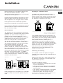
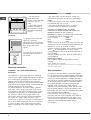
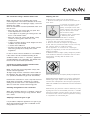
1
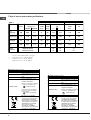
kitchen think Instructions for Installation and Use 90cm Free Standing Gas Cooker C90DPX To the Installer Before installation fill in the product details on the back cover this book. The information can be found on the rating plate. To the User You must read the instructions prior to installing and using the appliance and then retain them for future reference. Operating Instructions COOKER AND OVEN GB GB English,2 Contents Installation, 3-6 Room ventilation Disposing of combustion fumes Positioning and levelling Electrical connection Gas connection Table of burner and nozzle specifications Table of characteristics Description of the appliance, 7 Overall view Control panel Start-up and use, 8-13 C90DPX Using the hob Setting the time Using the oven Cooking modes for Multi-function (1rst Oven) Cooking modes for conventional-function (2nd Oven) Practical cooking advice Oven cooking advice table Precautions and tips, 15 General safety Disposal Respecting and conserving the environment Care and maintenance, 16 Switching the appliance off Cleaning the appliance Replacing the oven light bulb Gas tap maintenance Assistance Electric drawer, 17 Key Contacts, back cover Installation Before operating your new appliance please read this instruction booklet carefully. It contains important information concerning the safe installation and operation of the appliance. Please keep these operating instructions for future reference. Make sure that the instructions are kept with the appliance if it is sold, given away or moved. Disposing of combustion fumes GB The disposal of combustion fumes should be guaranteed using a hood connected to a safe and efficient natural suction chimney, or using an electric fan that begins to operate automatically every time the appliance is switched on (see figure). The appliance must be installed by a qualified professional according to the instructions provided. Any necessary adjustment or maintenance must be performed after the cooker has been disconnected from the electricity supply. Room ventilation Fumes channeled outside The appliance may only be installed in permanentlyventilated rooms, in accordance with current national legislation. The room in which the appliance is installed must be ventilated adequately so as to provide as much air as is needed by the normal gas combustion process (the flow of air must not be lower than 2 m3/h per kW of installed power). The air inlets, protected by grilles, should have a duct with an inner cross section of at least 100 cm2 and should be positioned so that they are not liable to even partial obstruction (see figure A). These inlets should be enlarged by 100% - with a minimum of 200 cm2 - whenever the surface of the hob is not equipped with a flame failure safety device. When the flow of air is provided in an indirect manner from adjacent rooms (see figure B), provided that these are not communal parts of a building, areas with increased fire hazards or bedrooms, the inlets should be fitted with a ventilation duct leading outside as described above. Adjacent room Room requiring ventilation A B A Ventilation opening Increase in the gap between for comburent air the door and the flooring After prolonged use of the appliance, it is advisable to open a window or increase the speed of any fans used. Fumes channelled through straight a chimney or a branched flue system (reserved for cooking appliances) ! The liquefied petroleum gases are heavier than air and collect by the floor, therefore all rooms containing LPG cylinders must have openings leading outside so that any leaked gas can escape easily. LPG cylinders, therefore, whether partially or completely full, must not be installed or stored in rooms or storage areas that are below ground level (cellars, etc.). Only the cylinder being used should be stored in the room; this should also be kept well away from sources of heat (ovens, chimneys, stoves) that may cause the temperature of the cylinder to rise above 50°C. Positioning and levelling It is possible to install the appliance alongside cupboards whose height does not exceed that of the hob surface. Make sure that the wall in contact with the back of the appliance is made from a non-flammable, heatresistant material (T 90°C). To install the appliance correctly: • Place it in the kitchen, the dining room or the bedsit (not in the bathroom). • If the top of the hob is higher than the cupboards, the appliance must be installed at least 600 mm away from them. • If the cooker is installed underneath a wall cabinet, there must be a minimum distance of 420 mm between this cabinet and the top of the hob. This distance should be increased to 700 mm if the wall cabinets are flammable (see figure). 3 GB 420 mm. 900 mm. Min. Min. 420 mm. Min. min. 650 mm. with hood min. 700 mm. without hood HOOD • Do not position blinds behind the cooker or less than 200 mm away from its sides. • Any hoods must be installed according to the instructions listed in the relevant operating manual. Levelling If it is necessary to level the appliance, screw the adjustable feet into the places provided on each corner of the base of the cooker (see figure). The legs* fit into the slots on the underside of the base of the cooker. Electrical connection WARNING – THIS APPLIANCE MUST BE EARTHED. The appliance is designed to work with alternating current at the supply voltage and frequency indicated on the rating plate (situated on the rear part of the appliance and on the last page of the instruction booklet) or at the end of the instruction booklet. Make sure that the local supply voltage corresponds to the voltage indicated on the rating plate. To connect directly to the mains supply, a doublepole switch with a contact separation of at least 3 mm suitable for the load and complying with current standards and regulations, must be fitted between the appliance and the mains supply outlet. The yellow-green earth wire must not be interrupted by the switch. The supply cable must be in such a position that no part of it can reach a temperature of 50 °C above room temperature. Do not use adapters or shunts as they could cause heating or burning. Before connecting to the power supply, make sure that: 4 • the limiter valve and the domestic system can withstand the load from the appliance (see rating plate); • the supply system is efficiently earthed according to standards and laws in force; • the socket or double-pole switch are easily accessible when the appliance is installed. FAILURE TO OBSERVE THE ACCIDENTPREVENTION REGULATIONS RELIEVES THE MANUFACTURER OF ALL LIABILITY. Important: the wires in the mains lead are coloured in accordance with the following code: Green & Yellow - Earth Blue - Neutral Brown - Live As the colours of the wires in the mains lead may not correspond with the coloured markings identifying the terminals in your plug, proceed as follows: Connect the Green & Yellow wire to terminal marked “E” or or coloured Green or Green & Yellow. Connect the Brown wire to the terminal marked “L” or coloured Red. Connect the Blue wire to the terminal marked “N” or coloured Black. Replacing the cable Use a rubber cable of the type H05VV-F with a suitable cross section 3 x 2.5 mm². The yellow-green earth wire must be 2-3 cm longer than the other wires. Gas connection Connection to the gas network or to the gas cylinder may be carried out using a flexible rubber or steel hose, in accordance with current national legislation and after making sure that the appliance is suited to the type of gas with which it will be supplied (see the rating sticker on the cover: if this is not the case see below). When using liquid gas from a cylinder, install a pressure regulator which complies with current national regulations. To make connection easier, the gas supply may be turned sideways*: reverse the position of the hose holder with that of the cap and replace the gasket that is supplied with the appliance. Check that the pressure of the gas supply is consistent with the values indicated in the Table of burner and nozzle specifications (see below). This will ensure the safe operation and durability of your appliance while maintaining efficient energy consumption. Gas connection using a flexible rubber hose Make sure that the hose complies with current national legislation. The internal diameter of the hose must measure: 8 mm for liquid gas supply; 13 mm for methane gas supply. Once the connection has been performed, make sure that the hose: • Does not come into contact with any parts that reach temperatures of over 50°C. • Is not subject to any pulling or twisting forces and that it is not kinked or bent. • Does not come into contact with blades, sharp corners or moving parts and that it is not compressed. • Is easy to inspect along its whole length so that its condition may be checked. • Is shorter than 1500 mm. • Fits firmly into place at both ends, where it will be fixed using clamps that comply with current regulations. If one or more of these conditions is not fulfilled or if the cooker must be installed according to the conditions listed for class 2 - subclass 1 appliances (installed between two cupboards), the flexible steel hose must be used instead (see below). Adapting the hob Replacing the nozzles for the hob burners: 1. Remove the hob grids and slide the burners off their seats. 2. Unscrew the nozzles using a 7 mm socket spanner (see figure), and replace them with nozzles suited to the new type of gas (see Burner and nozzle specifications table). 3. Replace all the components by following the above instructions in reverse. Adjusting the hob burners minimum setting: 1. Turn the tap to the minimum position. 2. Remove the knob and adjust the regulatory screw, which is positioned inside or next to the tap pin, until the flame is small but steady. If the appliance is connected to a liquid gas supply, the regulatory screw must be fastened as tightly as possible: 3. While the burner is alight, quickly change the position of the knob from minimum to maximum and vice versa several times, checking that the flame is not extinguished. Connecting a flexible jointless stainless steel pipe to a threaded attachment Make sure that the hose and gaskets comply with current national legislation. To begin using the hose, remove the hose holder on the appliance (the gas supply inlet on the appliance is a cylindrical threaded 1/2 gas male attachment). Perform the connection in such a way that the hose length does not exceed a maximum of 2 metres, making sure that the hose is not compressed and does not come into contact with moving parts. Checking the tightness of the connection When the installation process is complete, check the hose fittings for leaks using a soapy solution. Never use a flame. The hob burners do not require primary air adjustment. After adjusting the appliance so it may be used with a different type of gas, replace the old rating label with a new one that corresponds to the new type of gas (these labels are available from Authorised Technical Assistance Centres). Should the gas pressure used be different (or vary slightly) from the recommended pressure, a suitable pressure regulator must be fitted to the inlet hose in accordance with current national regulations relating to regulators for channelled gas. Adapting to different types of gas It is possible to adapt the appliance to a type of gas other than the default type (this is indicated on the rating label on the cover). 5 GB GB Table of burner and nozzle specifications Table 1 Burner Liquid Gas Diameter (mm) Thermal Power kW (p.c.s.*) By-Pass Nozzle 1/100 1/100 Natural Gas Flow* g/h Nozzle 1/100 Nominal Reduced (mm) (mm) *** ** (mm) Flow* l/h Fast (Large)(R) 100 3,00 0,7 41 86 218 214 116 286 Semi Fast (Medium)(S) 75 1,90 0,4 30 70 138 136 96 157 Auxiliary (Small)(A) 55 1,00 0,4 30 50 73 71 71 95 Triple Ring (TC) 130 3,25 1,5 63 91 236 232 124 309 28-30 20 35 37 25 45 Nominal (mbar) Minimum (mbar) Maximum (mbar) Supply Pressures * ** *** 20 17 25 At 15°C and 1013 mbar - dry gas Propane P.C.S. = 50.37 MJ/kg Butane P.C.S. = 49.47 MJ/kg Natural P.C.S. = 37.78 MJ/m³ st TECHNICAL DATA (1 Oven ) Oven dimensions H:33;W:38;D:54 cm Volume 68 Lt may be adapted for use with any Burners type of gas shown on the data plate Voltage and frequency see data plate Directive 2002/40/EC on the label of electric ovens. Regulation EN 50304 ENERGY LABEL Energy consumption for Natural convection – heating mode: Traditional mode; Declared energy consumption for Forced convection Class – heating mode: Multi cooking Mode. EC Directives: 73/23/EEC dated 19/02/73 (Low Voltage) and subsequent amendments 89/336/EEC dated 03/05/89 (Electromagnetic Compatibility) and subsequent amendments 90/369/EEC dated 29/06/90 (Gas) and subsequent amendments - 93/68/EEC dated 22/07/93 and subsequent amendments - 2002/96/EC. 6 nd TECHNICAL DATA (2 Oven) Dimensions H:33.8;W:24.5;D:43.8 cm Volume 36 l may be adapted for use with any Burners type of gas shown on the data plate Voltage and frequency see data plate Directive 2002/40/EC on the label of electric ovens. Regulation EN 50304 ENERGY LABEL Energy consumption for Natural convection – heating mode: Traditional mode; EC Directives: 73/23/EEC dated 19/02/73 (Low Voltage) and subsequent amendments 89/336/EEC dated 03/05/89 (Electromagnetic Compatibility) and subsequent amendments 90/369/EEC dated 29/06/90 (Gas) and subsequent amendments - 93/68/EEC dated 22/07/93 and subsequent amendments - 2002/96/EC. Description of the appliance Overall view GB 3000W 1900W CONTROL PANEL 3250W 1900W 1000W 2nd OVEN Compartement opening 1nd OVEN Adjustable feet SAFETY DEVICES Ignition for GAS BURNERS Control panel TIMER knob THERMOSTAT knob (1st. OVEN) Knob (2nd. OVEN) SELECTOR THERMOSTAT BURNERS Control knob THERMOSTAT Indicator light(1st. OVEN) 1st. OVEN • GAS BURNERS differ in size and power. Use the diameter of the cookware to choose the most appropriate burner to cook with. SELECTOR knob (1st. OVEN) 2nd. OVEN knob (2nd. OVEN) THERMOSTAT Indicator light (2nd. OVEN) • Control Knobs for GAS BURNERS adjust the power or the size of the flame. • GAS BURNERS ignition enables a specific burner to be lit automatically. 7 Start-up and use GB Using the hob Using the oven Lighting the burners For each BURNER knob there is a complete ring showing the strength of the flame for the relevant burner. To light one of the burners on the hob: 1. Bring a flame or gas lighter close to the burner. 2. Press the BURNER knob and turn it in an anticlockwise direction so that it is pointing to the maximum flame setting . 3. Adjust the intensity of the flame to the desired level by turning the BURNER knob in an anticlockwise direction. This may be the minimum setting , the maximum setting or any position in between the two. The first time you use your appliance, heat the empty oven with its door closed at its maximum temperature for at least half an hour. Ensure that the room is well ventilated before switching the oven off and opening the oven door. The appliance may emit a slightly unpleasant odour caused by protective substances used during the manufacturing process burning away. Never put objects directly on the bottom of the oven; this will avoid the enamel coating being damaged. If the appliance is fitted with an electronic lighting device (see figure), press the BURNER knob and turn it in an anticlockwise direction, towards the minimum flame setting, until the burner is lit. The burner may be extinguished when the knob is released. If this occurs, repeat the operation, holding the knob down for a longer period of time. ! If the flame is accidentally extinguished, switch off the burner and wait for at least 1 minute before attempting to relight it. If the appliance is equipped with a flame failure safety device, press and hold the BURNER knob for approximately 2-3 seconds to keep the flame alight and to activate the device. To switch the burner off, turn the knob until it reaches the stop position 0. Practical advice on using the burners For the burners to work in the most efficient way possible and to save on the amount of gas consumed, it is recommended that only pans that have a lid and a flat base are used. They should also be suited to the size of the burner: To identify the type of burner, please refer to the diagrams contained in the “Burner and nozzle specifications”. For models equipped with a reducer grid, the latter must be used only for the auxiliary burner, when pans with a diameter of less than 12 cm are used. Burner ø Cookware Diameter (cm) Fast (R) 24 - 26 Semi Fast (S) 16 - 20 Auxiliary (A) 10 - 14 Triple Crown (TC) 24 - 26 8 In order to cool down the temperature of their exterior, some models are fitted with a cooling fan that comes on when the programme selector knob is turned. In this case, the fan is always on and a normal flow of air can be heard exiting between the oven door and the control panel. Note: when cooking is done, the fan stays on, even if knob is set to “0”, until the oven has cooled down sufficiently. In "Fast cooking" mode, the fan comes on automatically only when the oven is hot. Once you have removed the food from the oven, we recommend you leave the oven door ajar for a few minutes: this will drastically reduce the duration of the cooling cycle. The process is controlled by an additional thermostat and can consist of one or more cycles. 1. Select the desired cooking mode by turning the SELECTOR knob. 2. Select the recommended temperature for the cooking mode or the desired temperature by turning the THERMOSTAT knob. A list detailing cooking modes and suggested cooking temperatures can be found in the relevant table (see Oven cooking advice table). During cooking it is always possible to: • Change the cooking mode by turning the SELECTOR knob. • Change the temperature by turning the THERMOSTAT knob. • Stop cooking by turning the SELECTOR knob to the “0” position. Always place cookware on the rack(s) provided. THERMOSTAT indicator light When this is illuminated, the oven is generating heat. It switches off when the inside of the oven reaches the selected temperature. At this point the light illuminates and switches off alternately, indicating that the thermostat is working and is maintaining the temperature at a constant level. OPERATION indicator light When this is illuminated, the oven is generating heat. halfway through the cooking process. GB MULTI-COOKING mode Oven light This is switched on by turning the SELECTOR knob to any position other than “0”. It remains lit as long as the oven is operating. By selecting 8 with the knob, the light is switched on without any of the heating elements being activated. Cooking modes for Multi-function main oven (1 rst Oven) The first time you use your appliance, heat the empty oven with its door closed at its maximum temperature for at least half an hour. Ensure that the room is well ventilated before switching the oven off and opening the oven door. The appliance may emit a slightly unpleasant odour caused by protective substances used during the manufacturing process burning away. A temperature value can be set for all cooking modes between 50°C and Max, except for the following modes • MAXI-GRILL / MINI-GRILL (recommended: set only to MAX power level) • GRATIN (recommended: do not exceed 200°C). TRADITIONAL OVEN mode Both the top and bottom heating elements will come on. When using this traditional cooking mode, it is best to use one cooking rack only. If more than one rack is used, the heat will be distributed in an uneven manner. BAKING mode The rear heating element and the fan are switched on, thus guaranteeing the distribution of heat in a delicate and uniform manner throughout the entire oven. This mode is ideal for baking and cooking temperature sensitive foods (such as cakes that need to rise) and for the preparation of pastries on 3 shelves simultaneously. Z All the heating elements (top, bottom and circular) switch on and the fan begins to operate. Since the heat remains constant throughout the oven, the air cooks and browns food in a uniform manner. A maximum of two racks may be used at the same time. MINI-GRILL mode The central part of the top heating element is switched on. The high and direct temperature of the grill is recommended for food that requires a high surface temperature (veal and beef steaks, fillet steak and entrecôte). This cooking mode uses a limited amount of energy and is ideal for grilling small dishes. Place the food in the centre of the rack, as it will not be cooked properly if it is placed in the corners. MAXI-GRILL mode All the top heating element are activated . e GRATIN mode The top heating element and the rotisserie (where present) are activated and the fan begins to operate. This combination of features increases the effectiveness of the unidirectional thermal radiation provided by the heating elements through forced circulation of the air throughout the oven. This helps prevent food from burning on the surface and allows the heat to penetrate right into the food. The GRILL and GRATIN cooking modes must be performed with the oven door shut. Practical cooking advice Do not place racks in position 1 or 5 during fanassisted cooking. Excessive direct heat can burn temperature sensitive foods. MULTILEVEL PIZZA mode The circular heating elements and the elements at the bottom of the oven are switched on and the fan is activated. This combination heats the oven rapidly by producing a considerable amount of heat, particularly from the element at the bottom. If you use more than one rack at a time, switch the position of the dishes • Use positions 2 and 4, placing the food that requires more heat on the rack in position 2. • Place the dripping pan on the bottom and the rack on top. 9 GB GRILL Starting the oven • When using the GRILL cooking mode, place the rack in position 4 and the dripping pan in position 1 to collect cooking residues (fat and/or grease). When using the GRATIN cooking mode, place the rack in position 2 or 3 and the dripping pan in position 1 to collect cooking residues. • We recommend that the power level is set to maximum. The top heating element is regulated by a thermostat and may not always operate constantly. PIZZA MODE 1. Select the desired cooking mode by turning the SELECTOR knob. 2. Select the recommended temperature for the cooking mode or the desired temperature by turning the THERMOSTAT knob. A list detailing cooking modes and suggested cooking temperatures can be found in the relevant table (see Oven cooking advice table). • Use a light aluminium pizza pan. Place it on the rack provided. For a crispy crust, do not use the dripping pan as it prevents the crust from forming by extending the total cooking time. • If the pizza has a lot of toppings, we recommend adding the mozzarella cheese on top of the pizza halfway through the cooking process. Cooking modes for Conventional main oven (2nd oven) The first time you use your appliance, heat the empty oven with its door closed at its maximum temperature for at least half an hour. Ensure that the room is well ventilated before switching the oven off and opening the oven door. The appliance may emit a slightly unpleasant odour caused by protective substances used during the manufacturing process burning away. A temperature value can be set for all cooking modes between 60°C and Max, except for the following modes • MAXI-GRILL / MINI-GRILL (recommended: set only to MAX power level) During cooking it is always possible to: • Change the cooking mode by turning the SELECTOR knob. • Change the temperature by turning the THERMOSTAT knob. • Set the total cooking time and the cooking end time (see below). • Stop cooking by turning the SELECTOR knob to the “0” position. Never put objects directly on the bottom of the oven; this will avoid the enamel coating being damaged. Only use position 1 in the oven when cooking with the rotisserie spit. Always place cookware on the rack(s) provided. THERMOSTAT indicator light When this is illuminated, the oven is generating heat. It switches off when the inside of the oven reaches the selected temperature. At this point the light illuminates and switches off alternately, indicating that the thermostat is working and is maintaining the temperature at a constant level. Oven light This is switched on by turning the SELECTOR knob to any position other than “0”. It remains lit as long as the oven is operating. By selecting 8 with the knob, the light is switched on without any of the heating elements being activated. TRADITIONAL OVEN mode Both the top and bottom heating elements will come on. When using this traditional cooking mode, it is best to use one cooking rack only. If more than one rack is used, the heat will be distributed in an uneven manner. 10 GB PASTRY Mode The bottom heating element comes on. This mode is ideal for baking and cooking delicate foods - especially cakes that need to rise because the heat coming from the bottom helps the leavening process. Please note that it takes a considerable amount of time for the higher temperatures to be reached, therefore we recommend you use the “Convection Mode” in these cases. MINI GRILL The top central heating element comes on. The extremely high and direct temperature of the grill makes it possible to brown the surface of meats and roasts while locking in the juices to keep them tender. The grill is also highly recommended for dishes that require a high temperature on the surface: beef steaks, veal, rib steak, filets, hamburgers etc... Some grilling examples are included in the “Practical Cooking Advice” paragraph. MAXI GRILL The top heating element comes on. This mode can be used to brown food at the end of cooking. Practical cooking advice GRILL • When using the GRILL cooking mode, place the rack in position 4 and the dripping pan in position 1 to collect cooking residues (fat and/ or grease). • We recommend that the power level is set to maximum. The top heating element is regulated by a thermostat and may not always operate constantly. The GRILL cooking mode must be performed with the oven door shut. 11 GB TIMER (ELECTRIC OVEN) The programmer makes it possible to preset the oven and the grill in terms of: • delay start with a preset length of time for cooking; • immediate start with a preset length of time for cooking; • timer. Button functions: : Timer with hour and minutes; : Length of cooking time; : End cooking time; Release the button, and within 4 seconds, the current time will reappear with the symbol and "auto." 3. Press the button, and then use the - and + buttons to set the end cooking time. Let us suppose that it is 13:00 4. Release the button and the display will show the current time within 4 seconds: : Manual change; - : Change time (backwards); + : Change time (forwards). How to Reset the Digital Clock After the appliance has been connected to the power source or following a power outage, the clock display will begin to blink and read: 0:00 buttons at the same time. Then Press the use (within 4 seconds) the - and + buttons to set the exact time. Use the + button to move the time forwards. Use the - button to move the time backwards. The time can also be changed in the following two ways: 1. Repeat all of the foregoing steps. When "auto" is lighted, it indicates that the length and end Cancelling a Preset Cooking Time button, and use the - button to set the Press the time to: • 2. Press the button, and then use the - and + buttons to reset the time. Manual Operation Mode for the Oven After the time has been set, the programmer is automatically set to manual mode. Note: Press the button to return the oven to manual mode after every "Automatic" cooking session. Delayed Start Time with Preset Cooking Length The length and the end cooking times must be set. Let us suppose that the display shows 10:00. 1. Turn the oven control knob to the cooking setting and temperature desired (example: convection oven at 200°C). and the use (within 4 seconds) the 2. Press the and + buttons to set the length of the cooking time. Let us suppose that 30 minutes was set for the length of the cooking time. In this case, the display will show: 12 Then press the manual cooking mode button . Timer Feature The timer can be used to count down from a given length of time. This feature does not control when the oven comes on or turns off, but, rather, it only emits an acoustic signal when the preset time has run out. Press the button, and the display will read: Then use the - and + buttons to set the desired time. Release the button, and the timer will start at that second. The display will show the current time. At the end of the preset time, an acoustic signal will sound, which can be turned off by pressing any button (except the - and + buttons), and the symbol will turn off. Changing and Cancelling Settings • The settings can be changed at any time by pressing the corresponding button and using the or + button. • When the length setting for the cooking time is cancelled, the end cooking time setting is also cancelled, and vice versa. • When in automatic cooking mode, the appliance will not accept end cooking times prior to the start cooking time proposed by the appliance itself. Multi funcituon Oven cooking advice table (1rst Oven) Cooking times shown in the charts are approximate and may vary according to personal taste. When cooking a certain food for the first time, it is advisable to choose the lowest values in the cooking time range given in the table and then increase times if necessary. Cooking modes Foods Duck Traditional Roast veal or beef Pork roast Oven Biscuits (short pastry) Tarts Tarts Fruit cakes Plum cake Sponge cake Stuffed pancakes (on 2 racks) Baking Mode Small cakes (on 2 racks) Cheese puffs (on 2 racks) Cream puffs (on 3 racks) Biscuits (on 3 racks) Meringues (on 3 racks) Pizza Pizza Mode Roast veal or beef Chicken Pizza (on 2 racks) Lasagne Lamb Roast chicken + potatoes Mackerel MultiPlum cake Cream puffs (on 2 racks) cooking Biscuits (on 2 racks) Sponge cake (on 1 rack) Sponge cake (on 2 racks) Savoury pies Mini grill Maxi grill Gratin Grill cooking Toast Pork chops Mackerel Soles and cuttlefish Squid and prawn kebabs Cuttlefish Cod filet Grilled vegetables Veal steak Sausages Hamburgers Mackerels Toasted sandwiches (or toast) Grilled chicken Cuttlefish Weight (in kg) Rack Position Pre-heating time (minutes) Recommended temperature Cooking time (minutes) 1 1 1 1 0.5 1 0.7 0.5 1.2 0.6 0.4 0.7 0.7 0.5 0.5 1 1 1 1 1 1+1 1 1 0.5 0.5 0.5 1 1.5 3 3 3 3 3 3 2 or 3 3 3 2 and 4 2 and 4 2 and 4 1 and 3 and 5 1 and 3 and 5 1 and 3 and 5 3 2 2 or 3 2 and 4 3 2 2 and 4 2 2 2 and 4 2 and 4 2 2 and 4 3 15 15 15 15 15 15 15 15 15 15 15 15 15 15 15 15 10 10 15 10 10 15 10 10 10 10 10 10 15 200 200 200 180 180 180 180 180 160 200 190 210 180 180 90 220 220 180 230 180 180 200 180 170 190 180 170 170 200 65-75 70-75 70-80 15-20 30-35 20-30 40-45 40-50 25-30 30-35 20-25 15-20 20-25 20-25 180 15-20 25-30 60-70 15-20 30-35 40-45 60-70 30-35 40-50 20-25 10-15 15-20 20-25 25-30 n.°4 1.5 1.1 2 and 3 2 and 3 2 and 3 - - 10 30 35 0.7 0.6 0.6 0.8 0.4 0.8 0.6 0.6 1 4 and 6 1.5 1.5 4 4 4 4 3 or 4 4 4 4 4 4 2 2 10 10 Max Max Max Max Max Max Max Max Max Max 200 200 10-12 8-10 10-15 10-15 15-20 15-20 15-20 10-12 15-20 3-5 55-60 30-35 13 GB GB Conventional Oven cooking advice table (2nd Oven) Cooking modes Traditional PASTRY OVEN Mini Grill Maxi Grill 14 Foods Lasagne Cannelloni Baked pasta Veal Chicken Duck Rabbit Pork Lamb Mackerel Mackerel Trout baked in foil Neapolitan-style pizza Biscuits and small cakes Sweet unleavened flans and desserts Savoury pies Leavened cakes Fruit cakes Perfecting cooking Sole and cuttlefish Squid and prawn kebabs Cod fillet Grilled vegetables Veal steak Chops Hamburgers Mackerel Toast With the rotisserie spit Spit-roast veal Spit-roast chicken Weight (in kg) Rack position Preheating time (min) 2.5 2.5 2.0 1.7 1.5 1.8 2 2.1 1.8 1.1 1.5 1 1 0.5 1.1 1 0.5 1 2 3 3 2 3 3 3 3 3 2 2 2 2 3 3 3 3 3 1 1 1 1 1 1.5 1 1 4 pcs 1.0 2.0 5 5 5 10 10 10 10 10 10 5 5 5 15 10 10 10 10 10 Recommended Temperature (°C) 200 200 200 180 200 180 180 180 180 180 180 180 220 180 180 180 160 170 Cooking time (minutes) 45-50 30-35 30-35 60-70 80-90 90-100 70-80 70-80 70-80 30-40 30-35 25-30 15-20 10-15 25-30 30-35 25-30 25-30 2 and 3 and 3 2 and 3 3/4 4 4 3 4 4 5 5 5 5 5 5 5 5 5 Max Max Max Max Max Max Max Max Max 8 4 10 8-10 15-20 20 7 15-20 5 - 5 5 Max Max 70-80 70-80 Precautions and tips This appliance has been designed and manufactured in compliance with international safety standards. The following warnings are provided for safety reasons and must be read carefully. General safety The appliance was designed for domestic use inside the home and is not intended for commercial or industrial use. The appliance must not be installed outdoors, even in covered areas. It is extremely dangerous to leave the appliance exposed to rain and storms. Do not touch the appliance with bare feet or with wet or damp hands and feet. The appliance must be used by adults only for the preparation of food, in accordance with the instructions provided in this booklet. The instruction booklet accompanies a class 1 (insulated) or class 2 - subclass 1 (recessed between 2 cupboards) appliance. Do not touch the heating elements or certain parts of the oven door when the appliance is in use; these parts become extremely hot. Keep children well away from the appliance. Make sure that the power supply cables of other electrical appliances do not come into contact with the hot parts of the oven. The openings used for the ventilation and dispersion of heat must never be covered. Always use oven gloves when placing cookware in the oven or when removing it. Do not use flammable liquids (alcohol, petrol, etc...) near the appliance while it is in use. Do not place flammable material in the lower storage compartment or in the oven itself. if the appliance is switched on accidentally, they could catch fire. The internal surfaces of the compartment (where present) may become hot. Always make sure the knobs are in the “0” position when the appliance is not in use. When unplugging the appliance, always pull the plug from the mains socket; do not pull on the cable. Never perform any cleaning or maintenance work without having disconnected the appliance from the electricity mains. If the appliance breaks down, under no circumstances should you attempt to perform the repairs yourself. Repairs carried out by inexperienced persons may cause injury or further malfunctioning of the appliance. Contact Assistance. Do not rest heavy objects on the open oven door. Before operating the product, remove all plastic film from the sides of the appliance. Disposal When disposing of packaging material: observe local legislation so that the packaging may be reused. The European Directive 2002/96/EC relating to Waste Electrical and Electronic Equipment (WEEE) states that household appliances should not be disposed of using the normal solid urban waste cycle. Exhausted appliances should be collected separately in order to optimise the cost of re-using and recycling the materials inside the machine, while preventing potential damage to the atmosphere and to public health. The crossed-out dustbin is marked on all products to remind the owner of their obligations regarding separated waste collection. For further information relating to the correct disposal of exhausted household appliances, owners may contact the public service provided or their local dealer. Respecting and conserving the environment You can help to reduce the peak load of the electricity supply network companies by using the oven in the hours between late afternoon and the early hours of the morning. Always keep the oven door closed when using the GRILL and GRATIN modes: This will achieve improved results while saving energy (approximately 10%). Check the door seals regularly and wipe them clean to ensure they are free of debris so that they adhere properly to the door, thus avoiding heat dispersion. 15 GB Care and maintenance GB Switching the appliance off Inspecting the oven seals Disconnect your appliance from the electricity supply before carrying out any work on it. Cleaning the appliance Check the door seals around the oven regularly. If the seals are damaged, please contact your nearest Authorised After-sales Service Centre. We recommend that the oven is not used until the seals have been replaced. Never use steam cleaners or pressure cleaners on the appliance. Replacing the oven light bulb The stainless steel or enamel-coated external parts and the rubber seals may be cleaned using a sponge that has been soaked in lukewarm water and neutral soap. Use specialised products for the removal of stubborn stains. After cleaning, rinse well and dry thoroughly. Do not use abrasive powders or corrosive substances. The hob grids, burner caps, flame spreader rings and burners may be removed to make cleaning easier; wash them in hot water and non-abrasive detergent, making sure all burnt-on residue is removed before drying them thoroughly. 1. After disconnecting the oven from the electricity mains, remove the glass lid covering the lamp socket (see figure). 2. Remove the light bulb and replace it with a similar one: voltage 230 V, wattage 25 W, cap E 14. 3. Replace the lid and reconnect the oven to the electricity supply. Gas tap maintenance Clean the terminal part of the flame failure safety devices* frequently. Over time, the taps may become jammed or difficult to turn. If this occurs, the tap must be replaced. The inside of the oven should ideally be cleaned after each use, while it is still lukewarm. Use hot water and detergent, then rinse well and dry with a soft cloth. Do not use abrasive products. This procedure must be performed by a qualified technician authorised by the manufacturer. Clean the glass part of the oven door using a sponge and a non-abrasive cleaning product, then dry thoroughly with a soft cloth. Do not use rough abrasive material or sharp metal scrapers as these could scratch the surface and cause the glass to crack. The accessories can be washed like everyday crockery, and are even dishwasher safe. Do not close the cover when the burners are alight or when they are still hot. The internal surfaces of the compartment (where present) may become hot. 16 Assistance Never use the services of an unauthorised technician. Please have the following information to hand: The type of problem encountered. The appliance model (Mod.). The serial number (S/N). The latter two pieces of information can be found on the data plate located on the appliance. Electric drawer GB 1 0 2 3 SELECTOR knob OPERATION indicator light The heated compartment makes it possible to: Leaven dough and defrost food (position 1 on the selector knob). Reheat food and keep it warm (positions 2 and 3 on the selector knob). Heat up pans and crockery (position 1on the selector knob). The appliance only heats up if the compartment has been closed properly. To activate the desired function: 1. Open the compartment by pressing gently on the front panel (push/push mechanism). 2. Place the crockery or the food to be leavened/ defrosted/reheated inside. 3. Select a function using the SELECTOR knob. The OPERATION indicator light illuminates. 4. Close the compartment. 5. A heating element will be activated, thus enabling the selected programme to be performed. To stop the function, open the compartment and turn the SELECTOR knob to 0. The OPERATION indicator light will switch off. 17 GB 18 GB 19 Key Contacts After Sales Service Over 1200 trained specialists, directly employed by us, ensure that you can have complete confidence in both the appliances and services we offer. Repair Service and Information Desk UK: 08709 066 066 (Open 8 to 8 Mon - Fri, 8 to 6 Sat, 10 to 4 Sun & Bank Holidays) www.cannonservice.co.uk Republic of Ireland: 1850 302 200 Note: Our operators will require the following information: Model number: Serial number: Extended Warranties UK: 08709 088 088 (Open 8 to 8 Mon - Sun) www.cannonservice.co.uk Republic of Ireland: 1850 502 200 Genuine Parts and Accessories UK: 08709 077 077 (Open 8-30 to 5-30 Mon - Fri & 9 to 12 Sat) www.cannonservice.co.uk Republic of Ireland: (01) 842 6836 www.cannoncooking.co.uk Indesit Company UK LTD, Morley Way, Peterborough, PE2 9JB. 07/2007 - 19506021700