1
http://waterheatertimer.org/Review-GE-Heat-Pump-water-heater.html
HP 200-1 E AI-F
Compress 3000
Electric Heat Pump Water Heater
http://waterheatertimer.org/Review-GE-Heat-Pump-water-heater.html
6 720 646 804 (2011/06) US
6720646804-00.1V
Index
Index
1
Warnings
3
6
Troubleshooting/Problem Solving
26
2
2.1
2.2
2.3
2.4
5
5
5
7
7
Electrical diagram
33
8
Interior components and parts list
34
2.5
Appliance details
Overview
Features and safety devices
Specification tables
Principle of Operation
(brief overview of modes)
Dimensions
9
Protecting the environment
36
3
3.1
3.2
3.3
3.4
3.5
3.6
3.7
3.8
3.9
3.10
Installation instructions
Tools required
Location requirements
Venting (specifications and vent runs)
Water piping
Electric requirements
Installation configurations
Insulation blanket
Filling the water heater
Installation checklist
What to expect for “normal startup”
10
10
10
11
11
13
14
16
16
16
17
10
Limited Warranty
37
4
4.1
4.2
4.3
4.4
4.5
4.6
4.7
Operating Instructions
Control Pad
Safety warnings
Water temperature setting
Operating modes
Feature buttons on the user interface
Using the combination buttons
Reset the temperature limiting control
18
18
20
20
21
21
21
22
5
5.1
5.2
5.3
5.4
5.5
5.6
5.7
5.8
Maintenance and repair
Periodic Inspection
Temperature and pressure relief valve
Flushing tank
Draining the Water Heater
Vacation and Extended Shutdown
Cleaning the Filter
Clearing the Condensation Drain Tubes
Anode Rod servicing
23
23
23
23
23
24
24
24
25
2
8
9
6 720 646 804
Warnings
1
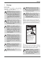
Warnings
For your safety
Warning: Precautions must be taken
prior to manually operating the relief
valve to avoid contact with hot water
which may cause a scalding injury and
to prevent water damage.
Do not store or use gasoline or other flammable,
combustible or corrosive vapors and liquids in the
vicinity of this or any other appliance.
Warning: Field wiring connections and
electrical grounding must comply with
local codes, or in the absence of local
codes, with the latest edition of the
National Electric Code, ANSI/NFPA 70,
or in Canada, all electrical wiring must
comply with the local codes and the
Canadian Electrical Code, CSA C22.1
Part 1.
Danger: Shock hazard: line voltage is
present. Before servicing the water
heater, disconnect power supply.
Failure to do so could result in severe
personal injury or death.
Caution: Label all wires prior to
disconnection when servicing controls.
Improper wiring may lead to shock
hazards and fires, which may cause
serious injury or death.
Verify proper operation after servicing.
FCC:
This device complies with Part 15 of the FCC rules.
Operation is subject to the following two conditions: (1)
This device may not cause harmful interference, and (2)
this device must accept any interference received,
including interference that may cause undesired operation.
Warning: The appliance should be
located in an area where leakage of the
heater or connections will not result in
damage to the area adjacent to the
appliance or to lower floors of the
structure. When such locations cannot
be avoided, a suitable drain pan,
adequately drained, must be installed
under the appliance.
DANGER
HOT
BURN
Warning: If a water heater is installed in
a closed water supply system, such as
one having a backflow preventer in the
cold water supply line, means shall be
provided to control thermal expansion
and to avoid the potential that the water
heater may burst. Contact a plumbing
professional on how to control this
situation.
Warning: To avoid the potential for ignition and fire, keep appliance area clear
and free from combustible materials,
gasoline and other flammable vapors
and liquids.
Warning: This water heater is not
suitable for pool heating.
6 720 646 804
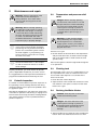
Water temperature over 120°F can
cause severe burns instantly or
death from scalds.
Children, disabled and elderly are
at highest risk of being scalded.
See instruction manual before
setting temperature at water
heater.
Feel water before bathing or
showering.
Fig. 1
To prevent serious injury, unit damage or damage to
other property, please use the electric heat pump
properly, please read this manual carefully and
understand the following information correctly.
Warning: Improper or incorrect
operation of the water heater can
create a hazardous condition that may
lead to serious injury or death. Read
this manual before installing or
operating the water heater.
3
Warnings
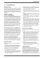
For installation in the state of California
California Law requires that residential water heaters
must be braced, anchored or strapped to resist falling
or horizontal displacement due to earthquake motions.
For residential water heaters up to 52 gallon capacity, a
brochure with generic earthquake bracing instructions
can be obtained from:
Office of the State Architect, 400 P Street,
Sacramento, CA 95814
or you may call 916.324.5315 or ask a water heater
dealer.
However, applicable local codes shall govern installation. For residential water heaters of a capacity greater
than 52 gallons, consult the local building jurisdiction
for acceptable bracing procedures.
The California Safe Drinking Water and Toxic Enforcement Act requires the Governor of California to publish
a list of substances known to the State of California to
cause cancer, birth defects, or other reproductive harm,
and requires businesses to warn of potential exposure
to such substances.
Proposition 65 Warning: this product contains a chemical known to the
State of California to cause cancer,
birth defects, or other reproductive
harm. This appliance can cause low-level exposure to some of the substances
included in the Act.
4
6 720 646 804
Appliance details
2
Appliance details
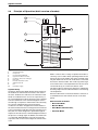
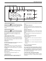
2.1
Overview
7
5
6
1
2
3
4
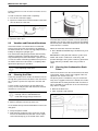
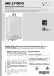
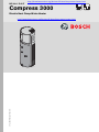
Fig. 2
1
2
3
4
5
6
7
Appliance overview
Temperature & pressure relief valve
Hot outlet
Cold intlet
Drain
Vent opening
Display
8" vent collar
i
2.2
6720646804-04.1V
Vent collar does not come installed on the
water heater.
air exchanger, heat may be taken from a mechanical
room or a sun porch or attic space, or from hot areas in
any other domestic environments.
Heating capacity
The unit absorbs ambient energy and releases the heat
into the water stored in the tank. If the ambient temperature is low, the heating capacity of the heat pump will
be reduced, but you can still rely on the electrical elements for backup.
Features and safety devices
Environmentally friendly and safe
Produces no harmful gas locally from the combustion of
oil, coal, or gas and is free of potential hazards from carbon monoxide.
Easy to operate and multiple heat sources
Easy to use adjustment keys for easy setting of the
water temperature. Depending upon the location of the
6 720 646 804
5
Appliance details
Temperature limiting controls (TCOs)
The water heater is equipped with two temperature-limiting controls (TCOs) that are located above the upper
heating heating element in contact with the tank surface. If for any reason the water temperature becomes
excessively high, the temperature-limiting control (TCO)
breaks the power circuit to the heating element. Once
the control opens, it must be reset manually. Resetting
of the temperature limiting controls should be done by
a qualified service technician.
Caution: The cause of high
temperature conditions must be
investigated by a qualified service
technician and corrective action must
be taken before placing the water heater
in service again.
Defrosting
Under the heating mode, the unit will shut down the
heat pump automatically if an unusually low temperature
is detected at the evaporator. This cycle can last
between 2 and 10 minutes and ensures maximum heating efficiency.
The fan motor will stop running when the unit is defrosting.
Working conditions
In order to use the unit correctly, please run the unit at
ambient temperature 45°F - 115°F.
The unit includes sophisticated electronic devices, care
should be taken to feed the unit only with potable water.
Do not use untreated water from lakes, rivers or
untreated groundwater!
Overheating protection
When the water temperature reaches 165°F power to
the unit will be cut off (see section 4.7 for instructions
on resetting the temperature limiter).
Water temperature or pressure protection
The unit is equipped with a T&P valve for your safety. If
the tank pressure reaches 150PSI or the temperature
reaches 210°F, the T&P valve will open automatically to
relieve the pressure and or reduce the temperature to
safe limits.
6
6 720 646 804
Appliance details
2.3
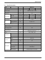
Specification tables
Model
HP200-1E...
Running models
Economy
Auto
E-heater
45 - 115
45 - 115
-5 - 130
Running ambient temp.
°F
Outwater Temp.
°F
Default 120°,100°F - 140°F
Power supply
Ph/V/Hz
1-240-60
Storage size
US Gal
50
Water heating
Capacity
kW / BTU/h
1.50 / 5123
1.50 / 5123
4.00 / 13661
Max. input
kW / BTU/h
0.80 / 2732
4.50 / 15368
4.00 / 13661
US Gal
-
56.00
52.00
A
6.5
21.6
18.7
First Hour Rating
Max. current
Ambient temp.
Unit
°F
- 5 - 130
Dimension (D×H)
inch
Ø22.4 × 64.5
Packing (W×H×D)
inch
25 × 68.5 × 27
Weight
lbs
209.4 / 242.5
dB(A)
48
lbs
R134a/1.7
PSIA
331/86 at ambient 70°F
PSI
150
Noise level
Refrigerant type/quantity
Refrigerant design pressure
Tank design pressure
Throttling type
Thermal expansion valve
System protection
TCO, TDO, P&T valve, over-load protector temp.
ground fault protector etc.
Ft3/h
Air flow
Compressor
Model
FFC110HBX
Type
Piston
Brand
Embraco
Input
Fan motor
kW
YDK12-6B
Brand
welling
Speed
W
40
RPM
970/750/550
Water inlet pipe
Male NPT ¾
Water outlet pipe
Male NPT ¾
Drainage pipe
Hose fitting NPT ¾
PT valve joint
Female NPT ¾
Max. pressure
psi
Heat exchanger
E-heater
0.7
Model
Input
Water pipeline
13066 / 9888 / 7063
145
Dividing wall type heat exchanger
kW
4.0 × 2
Table 1
6 720 646 804
7
Appliance details
2.4
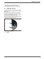
Principle of Operation (brief overview of modes)
2
3
9
8
1
7
4
5
10
4
6
6720646804-01.1V
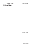
Fig. 3
1
2
3
4
5
6
7
8
9
10
Air Heat Exchanger
Compressor
Cooled / Dehumidified Air
Upper/Lower Electric element
Condensor Coil (heat exchanger)
Drain valve
Domestic Hot Water outlet
Ambient Room Air
Fan
Cold water supply
System theory
An Electric Heat Pump Water Heater draws heat from
the ambient air and transfers that heat to the water in
the tank. Ambient air inside the room where the water
heater is installed is blown across an evaporator by a
fan. Cold refrigerant inside an expansion valve is heated
from this ambient air. This warmed refrigerant is then
sent through a compressor where it becomes extremely
hot. The hot refrigerant then passes through a
condenser coil that is wrapped around the outside of
the tank. The heat from the hot refrigerant is transferred
to the stored water inside the tank. After transferring it's
heat, the now warm refrigerant is pushed through an
expansion valve where it is cooled and depressurized so
the process can begin again. In addition, the ambient air
is cooled and dehumidified as it passes through the
evaporator and can be used to adjust the climate of the
room.
8
Built in controls offer a variety of operational modes to
suit every user’s needs. When operating with the heat
pump only (Economic Mode), the water is heated using
only the ambient air. Economic mode does not activate
the electric element inside. This mode may take longer
to heat the water to set temperature but uses less than
1/2 the electricity of a similar size electric tank.
The Auto mode use the electric element to supplement
the heat pump in the event that the water is not reaching
set temperature.
Electric mode allows for the water heater to function as
a standard electric tank without the use of the heat
pump.
Brief overview of modes
• Economic Mode;
• Electric Mode;
• Auto Mode (default mode);
• Vacation Mode.
6 720 646 804
Appliance details
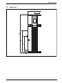
2.5
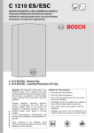
Dimensions
22.4
3.07
27.9
37.6
64.5
8
6720646804-03.1V
Fig. 4
Dimensions (inches)
6 720 646 804
9
Installation instructions
3
Installation instructions
Warning: This water heater SHOULD
NOT be installed in a space where
liquids which give off flammable vapors
are to be used or stored. Such liquids
include gasoline, LP gas (butane and
propane), paint or adhesives and their
thinners,
solvents
or
removers.
Because of natural air movement in a
room or other enclosed space,
flammable vapors can be carried from
where their liquids are being used or
stored. Any arc within the water
heater's electronic controls can ignite
these vapors causing an explosion or
fire which may result in severe burns or
death to those in range, as well as
property damage.
The manufacturer’s warranty does not cover any
damage or defect caused by improper installation,
attachment or use of any type of energy-saving or other
unapproved devices (other than those authorized by the
manufacturer) into, onto or in conjunction with the water
heater.
The manufacturer disclaims any responsibility for such
loss or injury resulting from the use of such
unauthorized devices.
3.1
Tools required
• Wrench ¾"
• Phillips screwdriver
• Flat screwdriver
• Wire strippers
• Level
• Measuring tape
• Standard plumbing tools.
3.2
Location requirements
Warning: To avoid the potential for
ignition and fire, the water heater should
not be installed in a space where liquids
which give off flammable vapors are to
be used or stored.
Locate the water heater in a clean, dry area as near as
practical to the area of greatest hot water demand.
Long uninsulated hot water lines can waste energy and
water.
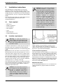
Note: Because this unit draws in air from the room to
heat the water, the room must be at least 10' x 10' x 7'
(700 cubic feet) or larger. If the room is smaller, there
must be louvers installed to allow for adequate airflow.
Place the water heater in such a manner that the air filter, cover and front panels can be removed to permit
inspection and servicing, such as removal of elements,
draining the tank, or cleaning of the filter.
The water heater and water lines should be protected
from freezing temperatures and highly corrosive atmospheres. Do not install the water heater in outdoor or
unheated, unprotected areas.
Caution: The water heater should not
be located in an area where leakage of
the tank or connection will result in
damage. In installations where risk of
water damage cannot be avoided, a
suitable catch pan, adequately drained,
must be installed under the water
heater.
10
Fig. 5
NOTE: Auxiliary catch pan MUST conform to local
codes. Catch Pan Kits are available from the store
where the water heater was purchased, a building supply store or any water heater distributor.
Local installation regulations
This water heater must be installed in accordance with
these instructions, local codes, plumbing codes (UPC
or IPC), utility codes, utility company requirements or, in
the absence of local codes, the latest edition of the
National Electrical Code. It is available from some local
libraries or can be purchased from the National Fire Prevention Association, Batterymarch park, Quincy, MA
02169 as booklet ANSI/NFPA 70.
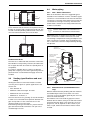
Required clearances
It is recommended that there is 5-½” of clearance (air
space) between any object and the front and rear
shrouds.
6 720 646 804
Installation instructions
5½”
5 ½”
6720646804-06.1V
Fig. 6
A 27” minimum vertical clearance is required to remove
the filter for cleaning and to replace the anode rod. The
hot and cold water plumbing and electrical connections
must not interfere with the removal of the filter.
3.4
Water piping
3.4.1
Inlet - Outlet connections
Refer to the illustration below for suggested typical
installation. The installation of unions or flexible copper
connectors is recommended on the hot and cold water
connections so that the water heater may be easily disconnected for servicing if necessary. The HOT and
COLD water connections are clearly marked and are
¾”NPT on all models.
Install a shut-off valve in the cold water line
near the water heater. This will enable easier service or maintenance of the unit later.
i
27”
IMPORTANT: Do not apply heat to the HOT or COLD
water connections. If sweat connections are used,
sweat tubing to adapter before fitting the adapter to the
water connections on heater. Any heat applied to the
hot or cold water connection will permanently damage
the dip tube.
To electrical
distribution panel
6720646804-05.1V
Fig. 7
Condensation drain
The unit has a condensate drain, therefore a drain must
be available in close proximity to the unit. The drain must
be no higher than 36” above the floor (laundry drain is
acceptable).
If no drain is available, then a common condensate
pump with a capacity no less than 1 gallon/day must be
purchased from a local builder and supply store and
installed.
3.3
Venting (specifications and vent
runs)
Electrical junction box
(use only copper
conductors)
Temperature and
pressure relief valve
(shown in different
location for clarity)
Union
Hot water outlet
to fixtures
Jacket
access panel
Union
To cold water
supply
Jacket
access panel
Thermal expansion
tank (if required)
6’ drain hose
Relief discharge
line to suitable
open drain
Auxiliary catch
pan 2” maximum
6” air gap
Drain valve
Venting the outlet air of the water heater to another
room may be an option for specific applications. See
Section 3.6.
• Duct diameter: 8”
• Maximum outlet duct length: 16.5 feet
• Maximum Air flow: 219 CFM
• Maximum no. of elbows: 1.
The vent collar accessory (see Fig. 2) must be installed
in order to accommodate the required 8" diameter vent
pipe. Line up tabs on vent collar with slots in vent
opening. Rotate to lock into place.
If terminating venting to the outdoors, pitch horizontal
pipe downward towards termination 1/4" per foot to
avoid damage from rain.
6 720 646 804
6720646804-09.1V
Fig. 8
Typical installation
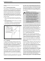
3.4.2
Dielectric union (recommended accessory)
Different metals between plumbing and tank materials
and additionally the effect of hot water can cause
corrosion of one of the metals (generally the one in the
tank is the metal attacked)
The Dielectric union will avoid any physical contact
between the two metals, acting as an effective insulator
and preventing this attack. How quick this corrosion
progresses, if at all, depends on the content of your
water, its pH, the dissolved minerals and the metals
involved.
11
Installation instructions
Failing to install this accessory will void the tank
warranty.
3.4.3
Condensate Drain Tubes
This unit has a condensation tray. The water collected
in the tray drains out of the drain ports coming off the
back of the unit. Two flexible hoses are included with
this unit. It is important that both of these hoses are
attached to the two drain ports coming off the back of
the unit. The upper drain serves as an overflow drain
that will operate only if the bottom drain is blocked.
Water leaking from the upper drain is an indicator that
the lower drain, and possibly the condensate pan itself,
require cleaning.
the outlet of the valve and must pitch downward from
the valve to allow complete drainage (by gravity) of the
relief valve and discharge line. The end of the discharge
line should not be threaded or concealed and should be
protected from freezing. No valve of any type, restriction, reducing coupling or tee should be installed in the
discharge line.
Warning: To reduce the risk of
excessive pressures and temperatures
in this water heater, install temperature
and pressure protective equipment
required by local codes and no less
than a combination temperature and
pressure relief valve certified by a
nationally recognized testing laboratory
that maintains periodic inspection of
production of listed equipment or
materials, as meeting the requirements
for Relief Valves for Hot Water Supply
Systems, ANSI Z21.22.
B Attach one end of the longer 6’ hose to the lower
drain port on the back of the unit, underneath the rear
cover.
B Direct the other end to a drain in the floor or no higher
than 3’ above the floor.
If such drain is unavailable, a condensate drain pump
(not provided) must be purchased and installed.
B Attach the shorter 3” hose to the top drain port.
This valve must be marked with a maximum set pressure
not to exceed the marked maximum working pressure of
the water heater. It should be installed into an opening
provided and marked for this purpose in the water
heater, and vented so that any discharge from the valve
exits only within 6 inches above, or at any distance
below, the structural floor, and does not contact any live
electrical part. The discharge opening must not be
blocked or reduced in size under any circumstances.
3.4.5
Fig. 9
3.4.4
T&P Valve
A combination temperature and pressure-relief valve,
complying with the Standard for Relief Valves for Hot
Water Supply Systems, ANSI Z21.22, is supplied and
must remain installed in the opening provided and
marked for the purpose on the water heater. No valve of
any type should be installed between the relief valve and
the tank. Local codes shall govern the installation of
relief valves.
Connect the outlet of the relief valve to a suitable open
drain so that the discharge water cannot contact live
electrical parts or persons and to eliminate potential
water damage. Under no circumstances should the
relief valve vent be connected to the condensate drain
line.
Piping used should be of a type approved for hot water
distribution. The discharge line must be no smaller than
12
Thermal expansion tank
Determine if a check valve exists in the inlet water
supply line. It may have been installed in the cold water
line as a separate backflow preventer, or it may be part
of a pressure-reducing valve, water meter or water
softener. A check valve located in the cold water inlet
line can cause what is referred to as a "closed water
system". A cold water inlet line with no check valve or
backflow prevention device is referred to as an "open"
water system.
As water is heated, it expands in volume and creates an
increase in the pressure within the water system. This
action is referred to as "thermal expansion". In an
"open" water system, expanding water which exceeds
the capacity of the water heater flows back into the city
main where the pressure is easily dissipated.
A "closed water system", however, prevents the
expanding water from flowing back into the main supply
line, and the result of "thermal expansion" can create a
rapid and dangerous pressure increase in the water
heater and system piping. This rapid pressure increase
can quickly reach the safety setting of the relief valve,
causing it to operate during each heating cycle. Thermal
expansion, and the resulting rapid and repeated
expansion and contraction of components in the water
heater and piping system, can cause premature failure
6 720 646 804
Installation instructions
of the relief valve, and possibly the heater itself.
Replacing the relief valve will not correct the problem!
The suggested method of controlling thermal expansion
is to install an expansion tank in the cold water line
between the water heater and the check valve. The
expansion tank is designed with an air cushion built in
that compresses as the system pressure increases,
thereby relieving the over-pressure condition and
eliminating the repeated operation of the relief valve.
Other methods of controlling thermal expansion are
also available. Contact your installing contractor, water
supplier or plumbing inspector for additional information
regarding this subject.
3.5
Electric requirements
Caution: Do not mis-wire electrical
connections. 240V AC must be applied
to L1 and L2 wires as shown in Fig. 10.
Failure to do so will VOID the warranty.
Connecting the water heater to 120V
AC may damage the compressor or
other electrical components.
Power requirements
Check the markings on the rating plate of the water
heater to be certain the power supply corresponds to
the water heater requirements.
Electrical connections
A separate branch circuit with copper conductors, overcurrent protective device and suitable disconnecting
means must be provided by a qualified electrician.
Fig. 10 Water heater junction box
Warning: Proper ground connection
is essential. The presence of water in
the piping and water heater does not
provide sufficient conduction for a
ground. Use of non-metallic piping,
dielectric unions, flexible connectors,
etc., can cause the water heater to be
electrically isolated, which may cause
fire or shock.
This water heater must be connected to the building
electrical system on a dedicated branch circuit. A
25amp circuit breaker must be installed for overcurrent
protection.
This water heater must be connected to the building's
electrical supply with 10AWG copper wire or larger.
If higher wattage elements are installed, consult the
National Electrical Code (NFPA 70) to determine the
proper circuit breaker and minimum wire size.
All wiring must conform to local codes or latest edition
of National Electrical Code ANSI/NFPA 70.
The water heater is completely wired to the junction box
at the top of the water heater. An opening for ½” or ¾”
electrical fitting is provided for field wiring connections.
The voltage requirements and wattage load for the
water heater are specified on the rating label on the
front of the water heater.
The branch circuit wiring should include either:
• Metallic conduit or metallic sheathed cable approved
for use as a grounding conductor and installed with
fittings approved for the purpose.
• Non metallic sheathed cable, metallic conduit or
metallic sheathed cable not approved for use as a
ground conductor shall include a separate conductor
for grounding. It should be attached to the ground
terminals of the water heater and the electrical distribution box.
6 720 646 804
13
Installation instructions
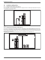
3.6
Installation configurations
3.6.1
Using heat from existing space (Fig. 11)
The water heater can remove heat from an area such as a garage or boiler room making the temperature in the space
more tolerable in the summer months.
6720646804-13.1V
Fig. 11
3.6.2
Cooling in the recirculating air mode (Fig. 12)
The room air is extracted from the storage room and is subsequently cooled and dehumidified in the electric heat
pump. The air is then piped to a wine cellar where the cool, dehumidified air can be utilized. Recreation rooms, boiler
rooms or utility rooms are ideal installation sites. The air duct leading through warm areas must be insulated to prevent
the formation of condensation.
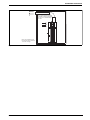
Alternatively, the cool air can be diverted outdoors if the cooling effect is not needed (Fig. 13).
6720646804-10.1V
Fig. 12
14
6 720 646 804
Installation instructions
Note: Pitch horizontal section
downward towards termination
1/4" per foot to avoid damage
from rain.
Note: vent termination may
be screened with a minimum
1/4" mesh or larger.
6720646804-12.1V
Fig. 13
6 720 646 804
15
Installation instructions
3.7
Insulation blanket
Contaminant
Recommended Level
If an insulation blanket is installed, the manufacturer’s
instructions included with the kit must be carefully followed.
Iron
Up to 0.3 mg/L
Manganese
Up to 0..05 mg/L
Application of any external insulation, blankets or water
pipe insulation to this water heater will require careful
attention to the following:
pH
6.5 to 8.5
Silver
Up to 0.10 mg/L
Sulfate
Up to 250 mg/L
TDS (Total Dissolved Solids)
Up to 250 mg/L
Zinc
Up to 250 mg/L
• Do not cover the temperature and pressure-relief
valve.
• Do not cover access panels to the heating elements.
• Do not cover the electrical junction box of the water
heater.
• Do not cover the operating or warning labels
attached to the water heater or attempt to relocate
them on the exterior of the insulation blanket.
• Do not block the air inlet grill or the exhaust vent
opening.
3.8
Filling the water heater
Warning: The tank must be full of
water before heater is turned on. The
water heater warranty does not cover
damage or failure resulting from
operation with an empty or partially
empty tank.
B Turn off power supply.
Table 2 Source: Part 143 National Secondary Drinking Water Regulations
1)
3.9
Hardness is not regulated by the National Secondary
Drinking Water Regulations
Installation checklist
1. Tank location
• Is room size less than 10’ x 10’ x 7’ (700 cu. ft.)? If
yes, louvered door or similar ventilation is needed.
• Is there 5-½” of clearance (air space) between any
object and the front and rear shrouds?
• Is front of unit free and clear?
• Use level to confirm water heater is exactly vertical. If
not condensate will not drain properly. Add shims as
needed under the base of the unit.
• Are bracing straps (if required) in place?.
2. Plumbing connections
B Make certain the drain valve is completely closed.
B Open the shut-off valve in the cold water supply line.
• Plumbing line must not block air filter removal on top
of the unit.
B Open a hot water faucet to purge air from the water
heater and piping.
• Check for leaks on plumbing lines and water heater
connections.
B A steady flow of water from the hot water faucet(s)
indicates a full water heater.
3. Condensate lines are in place
• Connect both drain lines. Connect longer condensate tube to lower drain and run to an appropriate
drain or condensate pump.
B Turn on power supply.
3.8.1
Water quality
If your water quality exceeds the levels in the table
below, you should consider treating or conditioning the
water entering the water heater. Bosch's warranty does
not cover product failures resulting from water quality
related issues.
Contaminant
Recommended Level
Total Hardness1)
More than 2 gpg
Aluminum
Up to 0.2 mg/L
Chlorides
Up to 250 mg/L
Copper
Up to 1.0 mg/L
Fluoride
Up to 2.0 mg/L
4. Ensure that the Temperature and PressureRelief Valve is operational and the drain line is
installed per local code.
5. Electrical connections
• Electrical connections do not prevent air filter
removal.
• Confirm that water heater electrical circuit is properly
isolated.
6. Verify control panel displays 120°F Auto mode.
7. Front cover is in place.
Table 2 Source: Part 143 National Secondary Drinking Water Regulations
16
6 720 646 804
Installation instructions
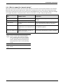
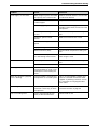
3.10 What to expect for “normal startup”
After the unit has been installed, with all electrical and water connections secure and checked, the unit should be
filled with water (vent tank by opening a hot water faucet somewhere in home to allow tank to fully fill with water).
Once tank is full and power is ON, the user must press the POWER button on the user interface. When the red light
on the upper left portion of the power button comes on, the heater is on and is ready to begin heating.
Approx. elapsed
time
HPWH actions
Comments
0 to 1.5 minutes
Unit is silent
1.5 to 3 minutes
Fans turn on
This 3 minute off-time prevents compressor
damage
3 to 8 minutes
Compressor turns on and runs for 5
minutes
This 5-minute period is used to ensure the tank
is full of water (Dry-fire prevention algorithm)
8 to 30 minutes
Compressor turns off, and Upper
Element turns on for about 20 minutes
To quickly provide initial amount of hot water for
user (about 25 gallons)
30 minutes and beyond
Upper element turns off and compressor turns back on
Uses efficient heat pump for majority of heating
Table 3
i
i
Note: The heat pump operating range is
45°F to 115°F. If the ambient temperature is outside of this range, the compressor will not be able to run and the backup
electric elements will be used until the ambient temperature returns to the operating
range.
Note: Unit automatically defaults to Auto
Mode.
6 720 646 804
17
Operating Instructions
4
Operating Instructions
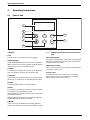
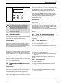
4.1
Control Pad
1
2
3
4
MODE
5
ENTER
8
7
press 3 seconds
for unlock
vacation
6
6720646804-02.1V
Fig. 14
1 Display
2 Up
4.1.1
Detailed description on the control function
Use up arrow to increase value or turn page up.
Auto lock function
3 Running light
If no buttons are pressed 1 minute, the control pad will
be locked. To deactivate the lock, press and hold the
lock pad for three seconds.
An illuminated light means the unit is running. When the
light is off the unit is not running. When the light is flashing the unit is in error or under protection.
Diagnostic function
4 Power
This is a service function for troubleshooting problems
and repair. See section 6.
For starting or shutting down the unit, note: when the
unit is in stand-by, the function still can be used.
Screen saver
5 Vacation
To extend the life of the screen, the screen will be
dimmed when there is no operation for one minute.
Press any key to activate the screen.
Use this button during times when no hot water will be
used, such as vacation for an extended period of time.
6 Down
For decreasing the value or turn page down.
7 Enter
For locking or unlocking the control pad. Press the button and the control pad will be locked.
When the panel is locked, press this key for 3 seconds
to deactivate the lock.
After changing the setpoint temperature through UP/
DOWN keys, press this key to confirm.
8 MODE
Users may choose between the following operating
modes: auto mode, economic mode and electric mode.
18
6 720 646 804
Operating Instructions
4.1.2
Description of LCD display
1
2
1
3
4
5
6
2
AUTO
7
ECO
8
SET TEMP
ELEC.
12
11
10
9
6720646804-15.2V
Fig. 15
1 Peak load shifting mode 1
Under this mode
will be illuminated. Heat pump
1
mode will run and users can set water temperature. This
mode will only appear when used in conjunction with a
Demand Response module (not available on this
model).
2 Peak load shifting mode
Under this mode
will be illuminated. Heat pump
2
mode will run and users cannot set water temperature.
The water temperature is set to be 110°F. This mode
will only appear when used in conjunction with a
Demand Response module (not available on this
model).
Note: when the unit is on auto mode this icon will flash
slowly.
8 Economic mode icon
Illuminates only when the unit is on Economic mode.
Note: when the unit is on Economic mode this icon will
flash slowly.
9 Electric mode icon
Illuminates only when the unit is on electric heat mode
and will be emitted when the unit is not on electric heat
mode.
Note: when the unit is on electric heat mode this icon
will flash slowly.
3 High temperature setting
10 Water temperature mode icon
If the temperature set by user or actual temperature is
above 120°F, this icon will be illuminated. It will not illuminate when the temp is 120°F or the unit is closed or
under screen saver mode.
There are 3 phases
• When 140°F TS 120°F, all 3 phases will be illuminated.
4 Lock icon
• When 120°F TS110°F, lower 2 phases will be
illuminated.
It will be illuminated when the control pad is locked, and
will be out when the pad is unlocked.
• When 110°FTS 100°F, lowest phase will be illuminated.
5 Alarm icon
Note: TS is preset water temperature.
It will flash when there is an error status or the unit is
under protection mode. In addition an alarm indicator
will buzz, and it will cease when the error or protection
is stopped.
11 Parameter display
6 Vacation mode icon
Reduces the required electrical energy during the
absence period.
Green light is illuminated when feature is on.
7 Auto mode icon
Illuminates when the unit is on auto mode and extinguishes when the unit is not under auto mode.
6 720 646 804
This icon illuminates when power supply is connected
and normally shows water temperature. When there is
an error or protection, it will show error code or protection code. When error or protection stops, it will show
water temperature again. When using the "query" function will show unit parameters.
12 Vacation time and diagnostic display
This icon is for setting the number of days for vacation
mode and is also used as a indicator when in diagnostic function.
19
Operating Instructions
4.2
Safety warnings
Warning: Hydrogen gas can be
produced in a hot water system served
by this water heater that has not been
used for a long period of time (generally
two weeks or more).
HYDROGEN GAS IS EXTREMELY
FLAMMABLE!
To dissipate such gas and to reduce
risk of injury, it is recommended that the
hot water faucet be opened for several
minutes at the kitchen sink before using
any electrical appliance connected to
the hot water system. If hydrogen is
present, there will be an unusual sound
such as air escaping through the pipe
as the water begins to flow. Do not
smoke or use an open flame near the
faucet at the time it is open.
Caution: Turn off power to water
heater if it has been subjected to
overheating, fire, flood or physical
damage.
4.3
The temperature of the water in the water heater can be
regulated by adjusting the temperature setting up or
down using arrow keys on the control panel.
Safety and energy conservation are factors to be considered when selecting the water temperature setting of
the water heater. The lower the temperature setting, the
greater the savings in energy and operating costs.
To comply with safety regulations, the water temperature is factory set at 120°F where local codes require.
This is the recommended starting point.
Water temperatures above 125°F can cause severe
burns or death from scalding. Be sure to read and follow
the warnings outlined in this manual and on the label on
the water heater. This label is located on the water
heater near the upper element access panel.
Mixing valves for reducing point-of-use water temperature by mixing hot and cold water in branch water lines
are available. Contact a licensed plumber or the local
plumbing authority for further information.
The chart below may be used as a guide in determining
the proper water temperature for your home.
Danger: There is a hot water scald
potential if the water temperature is set
too high. Households with small
children, disabled, or elderly persons
may require a 120°F or lower
thermostat setting to prevent contact
with HOT water that may cause
scalding and serious injury.
Caution: Do not turn on water heater
unless it is filled with water or internal
damage may occur.
Caution: To avoid thermal expansion
and the potential that the water heater
may burst, do not turn on water heater if
cold water supply shut-off valve is
closed.
Danger: To avoid the potential for
ignition and fire, do not store or use
gasoline or other flammable vapors and
liquids, such as adhesives or paint
thinner, in the vicinity of this or any
other appliance. If such flammables
must be used, open doors and
windows for ventilation.
Warning: If there's any difficulty in
understanding or following the
Operating Instructions or the Care and
Cleaning section, it is recommended to
have a qualified person or serviceman
performing the work.
i
20
Flammable vapours may be drawn by air
currents from surrounding areas to the
water heater.
Water temperature setting
Time/Temperature Relationship in Scalds
Temperature
Time to produce a serious burn
120°F
More than 5 minutes
125°F
1-1/2 to 2 minutes
130°F
About 30 seconds
135°F
About 10 seconds
140°F
Less than 5 seconds
145°F
Less than 3 seconds
150°F
About 1-1/2 seconds
155°F
About 1 second
Table 4
4.3.1
To adjust the temperature
B Press the UP or DOWN arrow on the control panel
key pad.
Then the temperature can be increased or decreased
by pressing the UP or DOWN arrows.
Finally press the ENTER button to confirm.
6 720 646 804
Operating Instructions
heating one day before your return, so that hot water will
be available.
MODE
ENTER
vacation
For example if you will be gone 14 days, press the
VACATION OR AWAY button, press the UP arrow
button until the display reads 14 days (the default is 14
days) and press ENTER. The unit will drop the water
temperature down to 50°F for 13 days. At the end of the
13th day, it will automatically return to the previous
operating mode and heat the water to the original
temperature setting.
press 3 seconds
for unlock
Control lock
6720646804-07.1V
The control pad can be locked out to prevent accidental
key presses.
Fig. 16
Danger: If the water temperature is set
too high, you may suffer a scalding injury from hot water; after you have set the
temperature setting, check the temperature of the water to ensure it is not too
hot. 120°F is the recommended water
temperature setting.
4.4
Operating modes
Simply press and hold the ENTER button for three
seconds. The display will show the lock icon when this
feature has been activated. No other key presses will be
allowed when the controls are locked.
To deactivate the lock, press and hold the ENTER pad
for three seconds. The screen will go to the default
display.
4.6
Using the combination buttons
This water heater defaults to the Auto operating mode.
The Auto mode is the recommended setting for this
water heater, but can be changed if desired.
By pressing select buttons on the control panel in
combination, a variety of options and parameters can be
changed.
Economic Mode
4.6.1
Economic is the the most energy-efficient mode for this
water heater. It takes heat from the surrounding air to
heat the water. The time it takes to heat the water is
longer in this mode, so it may NOT be sufficient if you
have a high-demand situation such as a large
household.
The water temperature display will default to °F.
Electric Mode
4.6.2
This mode uses only the upper and lower heating resistance elements to heat the water. The time it takes to
heat the water is less in this mode, but it is the LEAST
energy-efficient mode.
Auto Mode (recomended mode)
Auto mode combines the energy efficiency of Economic
with the recovery speed and power of the Electric
mode, with normal water usage.
4.5
Feature buttons on the user interface
Vacation mode
This feature is used when you will be away from the
home for an extended period of time and hot water is
not needed. In this mode, the unit will drop the water
temperature down to 50°F and will use the most
efficient heating mode to conserve energy while the
heater is sitting idle. The unit will automatically resume
6 720 646 804
°F and °C conversion
To show the temperatures in °C:
B Press the ENTER and MODE buttons simultaneously
for 1 second.
NOTE: To change back to °F, repeat the step above.
Inquire component’s parameter
To inquire component’s parameters:
B Press the ENTER and UP buttons simultaneously for
1 second.
NOTE: To exit the inquire function, repeat the step
above.
4.6.3
Clear malfunction
To clear a malfunction:
B Press the ENTER and DOWN buttons simultaneously for 1 second.
4.6.4
Clear an alarm
To clear an alarm:
B Press the ENTER and DOWN buttons simultaneously for 1 second.
21
Operating Instructions
4.7
Reset the temperature limiting
control
B Turn off power to the water heater.
B Pull off front cover below control pad (secured with
magnet). Remove upper jacket access panel (Fig. 8)
and insulation to access both temperature limiter
resets and insulation.
The thermostat protective cover should not be
removed.
B Press both red reset buttons to reset.
B Replace the insulation and jacket access panel(s)
before turning on the power to the water heater.
i
22
NOTE: if the power for the water heater is
turned off and then back on, the compressor will not start for 3 minutes to avoid internal damage.
6 720 646 804
Maintenance and repair
5
Maintenance and repair
Warning: Internal components of the
heater can become extremely hot
during operation. Use caution when
servicing and removing the front and
rear covers.
5.2
Danger: Before manually operating
the relief valve, make certain no one will
be exposed to the hot water released by
the valve. The water drained from the
tank may be hot enough to present a
scald hazard and should be directed to
a suitable drain to prevent injury or
damage.
Warning: Before manually operating
the relief valve, make certain no one will
be exposed to the danger of coming in
contact with the hot water released by
the valve. The water may be hot enough
to create a scald hazard. The water
should be released into a suitable drain
to prevent injury or property damage.
i
i
Temperature and pressure relief
valve
Warning: If a relief valve discharges
water periodically, this may be due to
thermal expansion in a closed water
supply system. Contact your installer or
service provider for assistance. Do not
plug the relief valve.
If the temperature and pressure-relief
valve on the hot water heater discharges
periodically, this may be due to thermal expansion in a closed water system. Contact
the water supplier or your plumbing contractor on how to correct this. Do not plug
the relief valve outlet.
At least once a year.
NOTE: If the power for the water heater is
turned off and then back on, the compressor will not start for 3 minutes to avoid internal damage..
Allow several gallons to flush through the discharge line
to an open drain.
Properly maintained, your water heater will provide
years of dependable trouble-free, economic service.
B lift and release the lever handle on the temperature
and pressure-relief valve, located on the back-right
side of the water heater to make certain the valve
operates freely.
5.3
Flushing tank
It is suggested that a routine preventive maintenance
program be established and followed by the user
A water heater’s tank can act as a settling basin for solids suspended in the water. It is therefore not uncommon for hard water deposits to accumulate in the
bottom of the tank.
5.1
To clean the tank of these deposits:
Periodic Inspection
It is further recommended that a periodic inspection of
the operating controls, heating elements and wiring
should be made by service personnel qualified in electric appliance repair.
Most electrical appliances, even when new, make some
sound when in operation. If the hissing or singing sound
level increases excessively, the electric heating element
may require cleaning. Contact a qualified installer or
plumber inspection.
B Open the drain valve located near the bottom of the
unit and drain a few quarts of water from the water
heater once a year.
5.4
Draining the Water Heater
Caution: Shut off power to the water
heater before draining water.
Danger: The water drained from the
tank may be hot enough to present a
scald hazard and should be directed to
a suitable drain to prevent injury or
damage.
B Attach a garden hose to the drain valve located at the
bottom of the unit and direct that hose to a drain.
6 720 646 804
23
Maintenance and repair
The decorative front cover must be removed to access
the valve.
In order to drain the water heater completely:
B Turn off the cold water supply.
B Open a hot water faucet or lift the handle on the relief
valve to admit air to the tank.
Fig. 17
Fig. 18
B Open the drain valve.
5.5
Vacation and Extended Shutdown
If the water heater is to remain idle for an extended
period of time, the power and water to the appliance
should be turned off to conserve energy and prevent the
buildup of dangerous hydrogen gas.
The water heater and piping should be drained if they
might be subjected to freezing temperatures. After a
long shutdown period, the water heater’s operation and
controls should be checked by qualified service personnel. Make certain the water heater is completely filled
again before placing it in operation.
i
5.6
Note: refer to the Hydrogen Gas Caution
in the Operating Instructions.
Cleaning the Filter
In the Auto and Economic modes, the heater moves air
through the system and out the back of the unit. The filter is in place to protect the evaporator from dirt and
dust.
A clean air filter is important to get the highest efficiency. Occasionally this filter will need to be cleaned
(minimum is once a year).
Once the filter has been cleaned, it can be replaced by
aligning it into the slot in the top of the unit and sliding
it down into place. When the handle is flush with the top
of the shroud, it is seated.
When the clean filter has been reinstalled:
B Press ENTER and DOWN keys simultaneously for 2
seconds.
IMPORTANT: A dirty filter will make the system work
harder and result in a reduction of efficiency and
possible damage to the system. In order to get the best
energy efficiency available, make sure your filter is
clean.
5.7
Clearing the Condensation Drain
Tubes
There are two drain hoses that are attached to the back
of the heater. If both of these get clogged, water will
spill down the outside of the unit.
The primary drain is intended to carry all condensate
away. If it is clogged or if the hose is kinked, the condensate will exit the secondary drain tube and onto the floor.
This is intended as a notification to the user that the primary drain is clogged.
B Remove the drain hose.
B Clear any debris and reattach.
i
If the filter gets too dirty, the unit will automatically switch to Standard Electric
mode and energy savings will be lost.
B Leave the power on.
B Remove the filter from the top of the unit.
It is located in the top of the unit behind the hot and cold
inlet pipes.
B Grasp the plastic handle
B Slide the filter straight up until it clears the shroud.
Once it has beed removed, the filter can be wiped
clean with a damp rag or rinsed with warm water.
Fig. 19
24
6 720 646 804
Maintenance and repair
B Periodically inspect the drain lines and clear any
debris that may have collected in the lines.
B See Installation Instructions for more information.
5.8
Anode Rod servicing
A water heater anode rod is the most important safety
guard any storage tank has against corrosion and premature failure.
Inspecting the anode rod is therefore very important.
Sacrificial rods are designed to deteriorate overtime.
Most water heating industry professionals recommend
inspecting the anode about every 2 years.
Homes with salty or softened water supplies should
consider more frequent inspection. When in doubt consult a local water heating professional.
1
2
6720646804-14.1V
Fig. 20 Water heater top view
1
2
Compressor
Anode Rod
6 720 646 804
25
Troubleshooting/Problem Solving
6
Troubleshooting/Problem Solving
i
NOTE: if the power for the water heater is
turned off and then back on, the compressor will not start for 3 minutes to avoid internal damage.
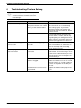
Problem
Cause
Solutions
Water heater is noisy.
Fans are used to move air through
the system. The fan noise volume
will vary as the water is heated.
Some amount of fan noise is normal (similar to the blower on a central heating
and cooling system). If you hear an
abnormal noise like a knocking or the
noise level seems unusually loud, please
contact service.
If noise level has been increasing over
the last weeks or months, the filter may
be getting dirty thus making the fan work
harder. Check to see if filter needs to be
cleaned. (See page 24 for instructions).
Water heater is making the
room too cold.
Room is not vented properly or is
too small.
If the room is smaller than 10’ x 10’ x 7’,
then a louvered door or other means to
allow air exchange with surrounding
rooms will be necessary.
Water dripping down the outside of the heater.
Condensate drain hoses are not
connected.
Two drain hoses are included with your
water heater. Connect the longer 6’ hose
to the lower condensate drain port. Connect the short 3” hose to the upper condensate drain port.
Condensate drain hoses are
kinked or clogged.
Remove each drain hose and clear any
debris from the line. You can use a small
wire like a hanger or a small screwdriver
to clear out any debris in the drain port
the unit.
Hot/Cold water connections are
not tightened.
Tighten the inlet and outlet pipe connections.
Table 5
26
6 720 646 804
Troubleshooting/Problem Solving
Problem
Cause
Solutions
Not enough or no hot water.
Water usage may have exceeded
the capacity of the water heater.
Wait for the water heater to recover after
an abnormal demand.
A fuse is blown or a circuit
breaker tripped.
Replace fuse or reset circuit breaker.
Electric supply may be off.
Make sure electric supply to water heater
and disconnect switch, if used, are in the
ON position.
Water temperature may be set
too low.
See the Water temperature setting section.
Leaking or open hot water
faucets.
Make sure all faucets are closed.
Electric service may be interrupted.
Contact the local electric utility supplier.
Improper wiring.
See the Installation Instructions section.
Manual reset limit (TCO).
See the Water temperature setting section.
Cold water inlet temperature may
be colder during winter months.
This is normal. The colder inlet water
takes longer to heat.
Water temperature is set too high.
See the Water temperature setting section.
Electronic control has failed.
Call for service.
Rumbling noise.
Water conditions in your home
caused a buildup of scale or mineral deposits on the heating elements.
Remove and clean the heating elements.
Relief valve producing popping
noise or draining.
Pressure buildup caused by thermal expansion to a closed system.
This is an unacceptable condition and
must be corrected. Contact the water
supplier or plumbing contractor on how
to correct this. Do not plug the relief
valve outlet.
The filter light is on.
The filter requires cleaning. A
clean filter is necessary for effective operation.
Follow the instructions on how to remove
and clean the filter on page 24.
Unit is not making noise.
If unit is using the electric elements, it will not make noise.
Check mode of unit.
Water is too hot.
Table 5
6 720 646 804
27
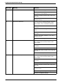
Troubleshooting/Problem Solving
Error code
Meaning
Solutions
E0
T2 sensor malfunction
1. Check wires for damage.
2. Check T2 sensor. Check wire connections
from sensor to control board.
3. Check T2 whether interfere with strong magnetic field.
4. Check actual temp. whether in O°C - 60°C
(tolerance +5°C).
E1
T3a sensor malfunction
1. Check wires for damage. Measure resistance
from control board connection. Refer to thermister table 8. This is a 55 kOhm thermister.
2. Check wire connections from sensor to control board.
3. Check T3a sensor damage or not (resistance).
4. Check T3a whether interfere with strong magnetic field.
5. Check actual temp. whether in -5°C - 30°C
(tolerance +5°C).
6. Check TXV for damage.
E4
T3b sensor malfunction
1. Check wires for damage. Measure resistance
from control board connection. Refer to thermister table 8.
2. Check wire connections from sensor to control board.
3. Check T3b sensor for damage.
4. Check T3b whether interfere with strong magnetic field
5. Check actual temp. whether in O°C - 30°C
E5
T4 sensor malfunction
1. Check wires for damage. Measure resistance
from control board connection. Refer to thermister table 8.
2. Check wire connections from sensor to control board.
3. Check T4 sensor for damage.
4. Check T4 whether interfere with strong magnetic field.
5. Check actual temp. whether in 30°C - 110°C
(tolerance 5°C)
6. Check refrigerant tubing for damage.
7. Check for refrigerant leakage.
Table 6
28
6 720 646 804
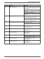
Troubleshooting/Problem Solving
Error code
Meaning
Solutions
E6
T5 sensor malfunction
1. Check wires for damage. Measure resistance
from control board connection. Refer to thermister table 7
2. Check wire connections from sensor to control board.
3. Check T5 sensor for damage.
4. Check T5 whether interfere with strong magnetic field.
E7
Heat pump malfunction
1. Heat pump has cycled off. If Temperature setting is >5°F above tank temperature, the heat
pump should restart within 15 minutes.
2. Spot inspection, check the last three error
codes to evaluate problem. Call service provider.
"LOCK + UP" Enter spot inspection.
E8
Water temperature is too high (T2 165°F)
1. Power off can resume.
2. Check actual water temperature. Replace T2
sensor if defective.
P0
Out of Run condition C
Run condition C:
T3a (30min) > 20°F
Cont. check after 30 min.
P1
Out of Run condition D
Run condition D:
T3b-T3a > 3°F
Cont. check after 30 min.
P2
Out of Run condition E
Run condition E:
T4 < 240°F
Cont. check
P4
Compressor current is too high
1. Check that supply voltage > 260 VAC.
2. Check compressor for damage.
P6
Out of Run condition A
Run condition A:
T4 (5 min) > T4 (0 min) + 15°F
One time check
P7
Out of Run condition B
Run condition B:
T4 > 100°F
Cont. check after 30 min.
Table 6
6 720 646 804
29
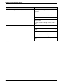
Troubleshooting/Problem Solving
Error code
Meaning
Solutions
P8
Upper Element has no current
1. Check power voltage whether in normal working range.
2. Check wire connections.
3. Check temperature limiters (TCOs).
4. Check upper heating element for damage.
5. Check the wire whether through current
sensor in PCB.
6. Check resistance through element (15.8 1
amp).
PA
Lower Element has no current
Check wire connections from sensor to control
board.
Check power voltage whether in normal working
range.
Check power code connect correct or not.
Check temperature limiters (TCOs).
Check lower element for damage.
Check resistance through element (15.8 1
amp)
Table 6
30
6 720 646 804
Troubleshooting/Problem Solving
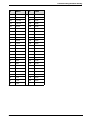
°C
KOhm
°C
KOhm
-40
336.00
85
1.070
-35
242.70
90
0.915
-30
177.00
95
0.787
-25
130.40
100
0.680
-20
97.06
105
0.592
-15
72.94
110
0.517
-10
55.32
115
0.450
-5
42.32
120
0.390
0
32.65
125
0.340
5
25.40
130
0.300
10
19.90
135
0.265
15
15.71
140
0.235
20
12.49
145
0.209
25
10.00
150
0.185
30
8.06
155
0.162
35
6.53
160
0.145
40
5.33
165
0.130
45
4.37
170
0.118
50
3.60
175
0.107
55
2.99
180
0.097
60
2.49
185
0.087
65
2.08
190
0.079
70
1.75
195
0.072
75
1.48
200
0.065
80
1.26
Table 7 Resistance table for T3a, T3b, T5 sensor
6 720 646 804
31
Troubleshooting/Problem Solving
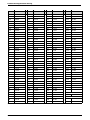
°C
KOhm
°C
KOhm
°C
KOhm
°C
KOhm
-20
542.7
20
68.66
60
13.59
100
3.702
-19
511.9
21
65.62
61
13.11
101
3.595
-18
483.0
22
62.73
62
12.65
102
3.492
-17
455.9
23
59.98
63
12.21
103
3.392
-16
430.5
24
57.37
64
11.79
104
3.296
-15
405.7
25
54.89
65
11.38
105
3.203
-14
384.3
26
52.53
66
10.99
106
3.113
-13
363.3
27
50.28
67
10.61
107
3.025
-12
343.6
28
48.14
68
10.25
108
2.941
-11
325.1
29
46.11
69
9.902
109
2.86
-10
307.7
30
44.17
70
9.589
110
2.781
-9
291.3
31
42.33
71
9.248
111
2.704
-8
275.9
32
40.57
72
8.94
112
2.63
-7
261.4
33
38.89
73
8.643
113
2.559
-6
247.8
34
37.30
74
8.358
114
2.489
-5
234.9
35
35.78
75
8.094
115
2.422
-4
222.8
36
34.32
76
7.82
116
2.357
-3
211.4
37
32.94
77
7.566
117
2.294
-2
200.7
38
31.62
78
7.321
118
2.233
-1
190.5
39
30.36
79
7.086
119
2.174
0
180.9
40
29.15
80
6.859
120
2.117
1
171.9
41
28.00
81
6.641
121
2.061
2
163.3
42
26.90
82
6.43
122
2.007
3
155.2
43
25.85
83
6.228
123
1.955
4
147.6
44
24.85
84
6.033
124
1.905
5
140.4
45
23.99
85
5.844
125
1.855
6
133.5
46
22.99
86
5.663
126
1.808
7
127.1
47
22.10
87
5.488
127
1.762
8
121.0
48
21.25
88
5.32
128
1.717
9
115.2
49
20.45
89
5.157
129
1.674
10
109.8
50
19.69
90
5.0
130
1.632
11
104.6
51
18.96
91
4.849
12
99.69
52
18.26
92
4.703
13
95.05
53
17.58
93
4.552
14
90.66
54
16.94
94
4.426
15
86.49
55
16.32
95
4.294
16
82.54
56
15.73
96
4.167
17
78.79
57
15.16
97
4.045
18
75.24
58
14.62
98
3.927
14.09
99
3.812
19
71.86
59
Table 8 Resistance table of T4 sensor
32
B (25/50) = 3950K
R (90°C) = 5K 3%
6 720 646 804
Electrical diagram
7
Electrical diagram
6720646804-17.1V
Fig. 21
6 720 646 804
33
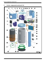
Interior components and parts list
8
Interior components and parts list
Fig. 22
34
6 720 646 804
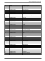
Interior components and parts list
Nr.
1
Code
8 738 721 051 0
Comp. description
Screen cover
2
8 738 721 052 0
Membrane
3
8 738 721 053 0
Back volute cover
4
8 738 721 054 0
Front shroud
5
8 738 721 055 0
Centrifugal fan assembly
6
8 738 721 060 0
Fan motor
7
8 738 721 062 0
Left rail
8
8 738 721 063 0
Wire connect box assembly
9
8 738 721 064 0
Wire connect box cover
10
8 738 721 065 0
Top cover
11
8 738 721 066 0
Air duct port
12
8 738 721 068 0
Steet net
13
8 738 721 069 0
Front volute cover
14
8 738 721 070 0
Right rail
15
8 738 721 072 0
Compressor
16
8 738 721 073 0
Air filter
17
8 738 721 074 0
Back shroud
18
8 738 721 244 0
Filter pipe II
19
8 738 721 245 0
TXV assembly
20
8 738 721 246 0
Accumulator assembly
21
8 738 721 247 0
Evaporator assembly
22
8 738 721 248 0
Gas discharging pipe assembly
23
8 738 721 249 0
Dryer
24
8 738 721 077 0
Upper electric heater cover
25
8 738 721 078 0
Lower electric heater cover
26
8 738 721 079 0
Front cover
27
8 738 721 044 0
Anode rod
28
8 738 721 045 0
Drain valve
29
8 738 721 046 0
Cover of T&P valve port
30
8 738 721 233 0
Water outlet pipe
31
8 738 721 047 0
T&P valve
32
8 738 721 048 0
Electric heater
33
8 738 721 235 0
Water inlet pipe
34
8 738 721 050 0
Cover of water inlet port
35
8 738 721 236 0
Relay
36
8 738 721 237 0
Two way relay
37
8 738 721 238 0
Capacitor
38
8 738 721 239 0
Capacitor holder
39
8 738 721 240 0
Transformer
40
8 738 721 241 0
Compressor capacitor
8 738 721 242 0
Mainboard assembly
41
Table 9
6 720 646 804
35
Protecting the environment
9
Protecting the environment
Packing
The packing box may be fully recycled as confirmed by
the recycling symbol
.
Components
Many parts in the heater can be fully recycled in the end
of the product life. Contact your city authorities for
information about the disposal of recyclable products.
Saving water resources:
B Make sure you close all the taps after any use. Avoid
leaving the taps dripping. Repair any leaking tap.
B Define the temperature you want, in the appliance.
This way you have the precise water flow needed
(mixing cold water to regulate temperature will
increase the water flow with consequent waste of
water).
Refrigerant
At the end of the service life of this appliance and prior
to it's envionmental disposal, a person qualified to work
with refrigerant circuits must recover the refrigerant
from within the sealed system.
Warning: The refrigerant must not be
vented to the atmosphere.
36
6 720 646 804
Limited Warranty
10
Limited Warranty
MODELS COVERED
This limited warranty is provided by Bosch
Thermotechnology Corp. (BTC) and covers Bosch
Compress 3000 Water Heater (hereinafter referred to
as "Water Heater"). This warranty is provided to the
original purchaser of the Water Heater as long as the
Water Heater remains installed at its original place of
installation.
WARRANTY COVERAGE
First Year - Limited Warranty
BTC warrants that the Water Heater shall remain free
from defects in workmanship and materials for ten years
from the date of original installation provided they are
installed and properly maintained by a qualified heating
contractor and the other conditions of this warranty are
met. If BTC determines that the Water Heater or any
part of Water Heater has a defect in workmanship or
materials, BTC, at its option, will repair or replace,
including labor charges at BTC approved rates, the
defective part for the first year from the date of original
installation, provided it is installed and properly maintained by a qualified heating contractor and the other
conditions of this warranty are met.
Second through Tenth Year - Limited Warranty
BTC warrants that the Water Heater shall remain free
from defects in workmanship and materials for ten years
from the date of original installation provided they are
installed and properly maintained by a qualified heating
contractor and the other conditions of this warranty are
met. If BTC determines that the Water Heater or any
part of Water Heater has a defect in workmanship or
materials, BTC, at its option, will repair or replace the
defective part. Labor charges are not included.
OTHER WATER HEATER COMPONENTS
The Water Heater may be installed with other components not manufactured by BTC ("Other Components).
Other Components are warranted by the manufacturer.
ITEMS NOT COVERED
This limited warranty does not cover the following circumstances:
1. Water Heater installed in a building other than a single family residential dwelling, unless individual
Water Heaters are installed for each dwelling unit.
2. Components or parts not provided by BTC.
3. Serviceable items and normal maintenance as
required per the Installation Manual.
4. The workmanship of any installer. BTC disclaims and
does not assume any liability of any nature for unsatisfactory performance caused by improper installation, repair or maintenance.
6 720 646 804
5. Any labor or material costs for removal, reinstallation,
repair and replacement of the defective component
or part unless otherwise provided above.
6. Transportation to BTC, if necessary.
7. Damage caused by abuse, accident, neglect, excessive water temperatures, freezing, flooding or acts of
God.
8. Damage caused by operation with either the temperature sensor rod or overheat sensor removed or T&P
valve obstruction.
9. Damage caused by scale deposits and/or highly mineralized/unsoftened water supply. See Installation
Manual for details.
10.Except as set forth above related to Other Components, components that are part of the water heating
system into which the Water Heater is incorporated
that are not Bosch products are not covered by this
warranty and are limited to the warranty of the manufacturer of such components. In order to file a claim
for warranty you should contact the manufacturer.
11.Shipping charges, delivery expenses or administrative fees incurred by the purchaser in repairing or
replacing the Water Heater.
CONDITIONS OF WARRANTY
The warranty herein is void under the following circumstances:
1. Failure or malfunction resulting from improper or negligent operation, accident, abuse, freezing, misuse,
unauthorized alteration or improper installation,
repair or maintenance. See the Owner's Manual for
installation and maintenance information.
2. Failure or malfunction resulting from operation of
Water Heater in a corrosive atmosphere or at water
temperatures exceeding the maximum rating.
3. Failure or malfunction resulting from operation of
Water Heater not supplied with potable water or is
operated with water that may cause deposits or corrosion.
4. Work performed without prior authorization or
approval and without authorization/requisition
number and without proper documentation verifying
compliance with above terms.
LIMITED WARRANTY
OTHER THAN THE OBLIGATIONS OF BTC
EXPRESSLY SET FORTH HERIN, BTC DISCLAIMS
ALL WARRANTIES, EXPRESS OR IMPLIED, INCLUDING BUT NOT LIMITED TO ANY IMPLIED WARRANTIES OF MERCHANTABILITY OR FITNESS FOR A
PARTICULAR PURPOSE. BTC'S SOLE OBLIGATION WITH RESPECT TO THE WATER HEATER AND
37
Limited Warranty
PURCHASER'S EXCLUSIVE REMEDIES ARE SET
FORTH IN THE FOREGOING LIMITED WARRANTY.
BTC SHALL NOT BE LIABLE FOR ANY INDIRECT,
PUNITIVE, INCIDENTAL, SPECIAL, CONSEQUENTIAL OR SIMILAR DAMAGES INCLUDING, WITHOUT
LIMIITATION, INJURY OR DAMAGE TO PERSONS
OR PROPERTY OR DAMAGES FOR LOSS OF USE,
LOST PROFITS, INCONVENIENCE OR LOSS OF
TIME.
NOTE THAT ANY REPAIRED OR REPLACED PRODUCT WILL BE WARRANTED FOR ONLY THE UNEXPIRED TERM OF THE ORIGINAL WARRANTY.
Some states do not allow the exclusion of limitation of
damages, or limitations on how long an implied warranty lasts, so the above limitations and exclusions may
not apply to you.
WARRANTY CLAIMS PROCESS
If you have a warranty claim you should notify the heating contractor who installed your Water Heater and ask
that the contractor notify the distributor from whom the
contractor purchased the Water Heater. If this action
is not possible or you don't receive a response, contact
Bosch Thermotechnology Corp., 50 Wentworth Avenue, Londonderry, NH 03053. To process your claim,
you will need a copy of your original invoice or other
proof of purchase and documentation showing the original installation date and location. The alleged defective
components or parts must be returned to BTC in
accordance with BTC procedure then in force for handling goods returned for the purpose of inspection to
determine cause of failure (contact BTC if you have
questions regarding the return process). If BTC determines that the returned components and/or parts are
defective and that this warranty applies, BTC will furnish
the repaired or replacement components and/or parts
to an authorized BTC distributor who, in turn, will forward the components and/or parts to the heating contractor who installed your Water Heater.
Effective for sales on or after 1/1/2011.
38
6 720 646 804
Limited Warranty
6 720 646 804
39
Replacement Parts available from:
BOSCH THERMOTECHNOLOGY
CORP.
50 Wentworth Avenue
Londonderry, NH 03053 USA
Tel. 866-330-2730
www.boschpro.com
© 2011 Bosch Thermotechnology Corp.,
Londonderry, NH