1
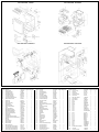
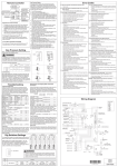
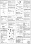
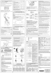
(Ensure gas pressure check under Commissioning has been completed
first !)
Error Codes
02
16 Over Temperature Warning
No burner operation during freeze protection mode
• Check for restrictions in air flow around unit and vent terminal.
• Check for low water flow in a circulating system causing short-
• Service Call
03 Power interruption during Bath fill (Water will not flow when
cycling.
power returns)
• Check for foreign materials in combustion chamber and/or
• Turn off all hot water taps. Press ON/OFF twice.
exhaust piping.
• Check for clogged heat exchanger.
10 Air Supply or Exhaust Blockage
Check gas type using data plate on side of unit.
If using spare PC board, check gas type switches (Fig.1) are in the
correct position. (dip switch 1 of SW2 ‘ON’ = NG, ‘OFF’ = LPG)
See Dip Switch Settings section below.
Note: ‘ON’ towards right, ‘OFF’ towards left.
•
•
•
•
•
•
•
32 Outgoing Water Temperature Sensor Fault
Ensure Rinnai approved venting materials are being used.
Check that nothing is blocking the flue inlet or exhaust.
Check all vent components for proper connections.
Ensure vent length is within limits.
Ensure condensation collar was installed correctly.
Verify dip switches are set properly.
Check fan for blockage.
•
•
•
•
33 Heat Exchanger Outgoing Temperature Sensor Fault
•
•
•
•
11 No Ignition
controller,
Set the Rinnai Water Heater to ‘Forced Low’ combustion by setting
No.7 dip switch of the (SW1) set of dip switches to ‘ON’. (Fig.3).
• Check that the gas is turned on at the water heater, gas meter,
or cylinder.
Ensure gas type and pressure is correct.
Ensure gas line, meter, and/or regulator is sized properly.
Bleed all air from gas lines.
Verify dip switches are set properly.
Ensure appliance is properly grounded.
Disconnect EZConnect or MSA controls to isolate the problem.
Ensure igniter is operational.
Check igniter wiring harness for damage.
Check gas solenoid valves for open or short circuits.
Remove burner cover and ensure all burners are properly
seated.
• Remove burner plate and inspect burner surface for
condensation or debris.
•
•
•
•
•
•
•
•
•
•
•
•
•
•
•
Check for restrictions in air flow around unit and vent terminal.
Check sensor wiring for damage.
Measure resistance of sensor.
Clean sensor of scale build up.
Ensure fan blade is tight on motor shaft and is in good
condition.
• Replace sensor.
52 Modulating Solenoid Valve Signal Abnormal
• Check modulating gas solenoid valve wiring harness for loose
or damage terminals.
• Measure resistance of valve coil.
61 Combustion Fan Failure
• Check that the gas is turned on at the water heater and gas
meter. Check for obstructions in the flue outlet.
Ensure gas line, meter, and/or regulator is sized properly.
Ensure gas type and pressure is correct.
Bleed all air from gas lines.
Ensure proper Rinnai venting material was installed.
Ensure condensation collar was installed properly.
Ensure vent length is within limits.
Verify dip switches are set properly.
Ensure appliance is properly grounded.
Disconnect keypad.
Disconnect EZConnect or MSA controls to isolate the problem.
Check power supply for loose connections.
Check power supply for proper voltage and voltage drops.
Ensure flame rod wire is connected.
Check flame rod for carbon build-up.
Disconnect and re-connect all wiring harnesses on unit and PC
board.
• Check all components for electrical short.
• Check gas solenoid valves for open or short circuits.
• Remove burner plate and inspect burner surface for
condensation or debris.
Burner
test point
SW1
1
SW2
Spare Parts
Only
APPLIANCE OPERATING PRESSURES
Table 1
LPG
5"W.C.
8"W.C.
150 PSI /10.5"W.C. /13.5"W.C. 0.65"W.C. 0.80"W.C. 2.8"W.C. 3.8"W.C.
should read 5"W.C. - 10.5"W.C. on Natural Gas and 8"W.C. - 13.5"W.C.
•
•
•
•
•
•
•
Troubleshooting
Heat Exchanger and Outgoing Water Temperature Thermistors:
2
3
ANTI-FROST
HEATER
AC120V
HOT
NEUTRAL
GROUND
W
W
W
W
W
W
D6
W
W
D5
W
FUSE
(3A)
GND
1
GND
G/Y
3
H7
Y
FLAME ROD
Y R
W BK
(CN12)
13
R Y
W BK D1
SURGE
PROTECTOR
W BK
1
1
BK
W
D
(CN3)
B
1
H
12
1
E
4
WW
P BL BR
G/Y
W BK D
2
GND
IG
1
3
1
2
3
4
5
6
O
F
F
(CN5)
1
(CN2)
A
H1
H2
MODULATING
SOLENOID VALVE POV O
O
H3
P
MAIN SOLENOID VALVE SV0 BK
H4
SOLENOID VALVE 1 SV1 R
BK
(CENTER)
H5
SOLENOID VALVE 2 SV2 O
BK
(LEFT)
H6
SOLENOID VALVE 3 SV3 Y
BK
(RIGHT)
WATER FLOW
CONTROL DEVICE
OVERHEAT
SWITCH
RR
R
BL
BR
Y
GY
F5
OUTGOING WATER
WATER THERMISTOR
HEAT EXCHANGER
WATER THERMISTOR
R
W
GY
R
BL
Y
BR
W
W
W
W
F4
W
P
W
W
R
Y
BK
QS
R
Y
BK
F2
WATER FLOW
SENSOR
BY-PASS FLOW
CONTROL DEVICE
FREEZE PROTECTION
(OPTIONAL)
F3
F1
G
R
W
Y
BK
R
R
W
1
2
3
4
5
6
DO NOT adjust the other dip switches unless specifically instructed
to do so. Incorrect Dip Switch Settings can cause the Rinnai water
heater to operate in an unsafe condition and may damage the water
heater and void the warranty.
SW
No.
GY F
ON
WARNING
High Altitude
RBK
O
F
F
1
2
3
4
5
6
7
8
5
1
2
3
4
5
6
ON
O
F
F
WY O RBR
O
F
F
BR
O
Y
R
W
The original PC boards on the water heaters do not
have the bank of 6 dip switches. Only spare PC
boards have this bank.
ON
1
2
3
4
5
6
7
8
G1
O
F
F
(CN7)
NAT.G
ON
1
LPG
Adjust switches 2 and 3 in the bank of 8 depending on
your altitude according to the table below.
G
R98LSe
R98LSe-ASME
Dip Switches Settings
D4
GY
GY
B1
BK
BK
Gas pressure
1
2
3
4
5
6
7
8
Dip SW2
F6 - H12
O
F
F
F6
H1
W RBK
Below 1 ohms
MAX
11 ~ 13 VDC
1
This unit has an inline (3) amp glass fuse. Remove the fuse and check continuity through it. If
Red - White
3
Thermal Fuse / Overheat Switch:
(CN9)
Using a voltage meter set on the 200 ohm scale, you should have a resistance reading. The
heater located on the heat exchanger piping should have a resistance reading of 139 ~ 161
ohms and the one located in the water flow sensor valve has a resistance reading of 335 ~ 385
ohms. The one located in the outlet valve has a resistance reading of 335 ~ 385. Voltage
throughout this circuit should be 120 VAC.
Gas type
Spare Parts Only
1-2
Dip SW1
C1
MODULATING VALVE
CURRENT ADJUSTING
N/A
(FM) Combustion Fan Motor:
Red - Black
6 ~ 45 VDC
N/A
E1
1-2
White - Black
5 ~ 10 VDC
9.2 ~ 9.4 K ohms
E1
2-4
Yellow - Black
11 ~ 13 VDC
3.5 ~ 3.9 K ohms
E1
2-3
Set your meter to the hertz scale. Reading across the white and black wires at terminals 2 and 4
you should read between 60 and 420 hertz.
IGNITER
This unit has six frost protection heaters mounted at different points inside the unit, to protect
(IG) Ignition System:
Grey - Grey
90 ~ 110 VAC
W
W
1-3
1.5 ~ 3.0 K ohms
(CN4)
10 ~ 13 VDC
F6
Remote Controls:
Terminals B1
THERMAL FUSES
1-5
2-5
3-5
4-5
#3
WW
B
1-3
2-3
D3
1-3
1-3
W
W
D2
D1
SPARK
ELECTRODE
N/A
N/A
C1
3 - 11
FROST SENSING
SWITCH
See example above F3
C
G1
G1
G1
G1
3-4
FM
By-pass Flow Control:
Brown - White
Orange - White
2 ~ 6 VDC
15 ~ 35 ohms
Yellow - White
(Unit in operating mode)
Red-White - Ground
See example above F4
BL BL
5.5 ~ 6.2 K ohms
F2
1 ~ 1.4 Mega ohms F2
flame at flame rod.
• Measure micro amp output of sensor circuit with flame present.
• Replace flame rod.
E1
COMBUSTION FAN
(QS) Water Flow Sensor:
Black - Red
11 ~ 13 VDC
Yellow - Black
4 ~ 7 VDC
9 - 10
5-7
5-8
sand paper.
• Check inside burner chamber for any foreign material blocking
Wiring Diagram
COLOR CODING
(M) Water Flow Control Device Servo or Geared Motor:
Red - Blue
11 ~ 13 VDC
22 ~ 28 ohms
F5
Grey - Brown
4 ~ 6 VDC
N/A
F5
Grey - Yellow
N/A
N/A
F5
NOTE: The grey wire listed above turns to black at F connector on the PCB.
• Ensure flame rod is touching flame when unit fires.
• Check all wiring to flame rod for damage.
• Remove flame rod and check for carbon build-up; clean with
LC Scale Build-up in Heat Exchanger (when checking
used.
maintenance code history “00” is substituted for “LC”)
Check for restrictions in air flow around unit and vent terminal.
• Flush heat exchanger. Refer to instructions in manual.
Check for low water flow in a circulating system causing shortcycling.
• Replace heat exchanger.
Ensure dip switches are set to the proper position.
No Code (Nothing happens when water flow is activated.)
Check for foreign materials in combustion chamber and/or
• Clean inlet water supply filter.
exhaust piping.
• On new installations ensure hot and cold water lines are not
Check heat exchanger for cracks and/or separations.
reversed.
Check heat exchanger surface for hot spots which indicate
•
Check for bleed over. Isolate unit from building by turning off
blockage due to scale build up. Refer to instructions in manual
hot water line to building. Isolate the circulating system if
for flushing heat exchanger.
present. Open your pressure relief valve; if unit fires, there is
Measure resistance of safety circuit.
bleed over in your plumbing.
Ensure high fire and low fire manifold pressure is correct.
•
Ensure you have at least the minimum flow rate required to fire
Check for improper conversion of product.
unit.
• Ensure turbine spins freely.
• Measure the resistance of the water flow control sensor.
• Remote control does not light up but you have 12 VDC at the
terminals for controls.
140°F = 2.2 ~ 2.7KΩ
221°F = 0.6 ~ 0.8KΩ
Outgoing Water Thermistor:
White - White
N/A
Heat Exchanger Temperature Thermistor:
Pink - White
N/A
Surge Protector:
Black - White
108 ~ 132 VAC
Black - White
108 ~ 132 VAC
72 Flame Sensing Device Fault
• Check gas type of unit and ensure it matches gas type being
•
•
59°F = 11.4 ~ 14KΩ
86°F = 6.4 ~ 7.8KΩ
113°F = 3.6 ~ 4.5KΩ
connections.
• Measure resistance of each solenoid valve coil.
14 Thermal Fuse
Regulator adjustment
screw access plug
(SV1, SV2, SV3 and POV) Gas valve and Modulating solenoids: (Set meter above 2K)
Wire color
Voltage
Resistance
Connector # Pin #'s
(Main) Pink - Black 11 ~ 13 VDC
24 ~ 28 ohms
H3
6-7
(SV1) Black - Red
11 ~ 13 VDC
37 ~ 43 ohms
H4
5-6
(SV2) Black - Orange 11 ~ 13 VDC
37 ~ 43 ohms
H5
4-6
(SV3) Black - Yellow 11 ~ 13 VDC
37 ~ 43 ohms
H6
3-6
(POV) Orange - Orange 2 ~ 15 VDC
67 ~ 81 ohms
H2
9 - 10
• Check wiring harness to all solenoids for damage and/or loose
REMOTE CONTROLLER
NAT.G
71 SV0, SV1, SV2, and SV3 Solenoid Valve Circuit Fault
1
LPG
If blank screen is present on remote control then the flow control
has shorted out. Unplug flow control. If remote lights up and unit
starts operating then replace flow control assembly.
(CN1)
NAT.G
MIN
R98LSe
R98LSe-ASME
LPG
65 Water Flow Servo Faulty (does not stop flow properly)
O P R Y Y
W O
BK O
NAT.G
Forced High
Forced Low
A1
for REU-EZC
(Optional)
Water
Inlet Max.
connections.
• Measure resistance of motor winding.
W :White
BK:Black
BR:Brown
R :Red
BL:Blue
Y :Yellow
P :Pink
O :Orange
G :Green
GY:Gray
Gas Inlet
Min./Max
• Ensure fan will turn freely.
• Check wiring harness to motor for damaged and/or loose
•
•
•
•
•
•
•
•
•
•
•
•
•
•
•
High Pressure
Potentiometer
Check sensor wiring for damage.
Measure resistance of sensor.
Clean sensor of scale build up.
Replace sensor.
34 Combustion Air Temperature Sensor Fault
12 Flame Failure
Gas Pressure Setting
Check sensor wiring for damage.
Measure resistance of sensor.
Clean sensor of scale build up.
Replace sensor.
GY
GY
Remote Controller
NOTES
High Altitude
Off
Off
Level 0
0-2000ft
(0-610m)
Off
On
Level 1
2001-5200ft
(610-1585m)
On
Off
Level 2
5201-7800ft
(1585-2377m)
On
On
Level 3
7801-10200ft
(2377-3109m)
R98LSe(VA3237W)
R98LSe-ASME
070 00012 35237 4
U273-1364(00)
EXPLODED VIEW - CABINET
EXPLODED VIEW - INTERNALS
EXPLODED VIEW - INTERNALS
EXPLODED VIEW - ELECTRICAL
703
Number
001
002
004
007
010
011
012
013
014
015
016
017
018
100
101
102
103
103
104
104
105
105
113
114
115
116
117
118
121
122
123
124
125
125
Description
Casing Assembly
Heat Protection Plate
Front Panel Assembly
Wall Installation Bracket
Front Panel Packing-Top
Front Panel Packing-Side
Connection Reinforcement Panel
Bag for Installation Manual
Seal Packing
Cable Access
Cable Access Packing
Rubber Bushing
Reinforcement Plate
Gas Connection(3/4"NPT)
Screw
Gas Control Assembly
Manifold Assembly-A(LPG)
Manifold Assembly-B(Nat.G)
Burner Unit Assembly(LPG)
Burner Unit Assembly(Nat.G)
Damper(LPG)
Damper(Nat.G)
Combustion Chamber Front Plate
Combustion Chamber Front Plate Packing
Electrode
Flame Rod
Electrode Packing
Electrode Holder
Electrode Sleeve
Solenoid Valve Cover
Upper Combustion Chamber Packing
Lower Combustion Chamber Packing
Heat Exchanger Complete Assembly
Heat Exchanger Complete Assembly
Quantity
Parts Number R98LSe R98LSe-ASME
109000067
1
1
H73-065
1
1
109000069
1
1
BU195-121
2
2
BU195-167
1
1
AU103-106
2
2
U273-115
1
1
CP-80736
1
1
AU105-113
1
1
BU56-602-N
1
1
109000071
1
1
CF79-41020-A
1
1
U273-113
1
1
CU195-1866
1
1
AU39-965
2
2
C36Q-7-AS
1
1
U273-200-A
1
1
U273-200-B
1
1
U273-240
1
1
106000024
1
1
U273-235
1
1
106000025
1
1
U211-266-2
1
1
U211-267
1
1
104000023
1
1
U250-295
1
1
AH66-398
1
1
AH66-393
1
1
AU206-218
1
1
U211-1027
1
1
U211-264
1
1
U211-268
1
1
U273-275-C-S
1
U273-1390-C
1
-
PARTS LIST
Quantity
R98LSe-ASME
R98LSe
Parts Number
Number Description
1
1
U211-351
131
Flue Outlet
1
1
U211-352
132
Flue Outlet Packing
1
1
AH24-653-4
133
Flue Outlet Packing-4
1
1
U250-565
150
Blower Motor
1
1
CH51-615
151
Fan Casing Assembly
1
1
153
U273-335
Fan Connecting Bracket
1
1
U211-552
154
Fan Connecting Packing
1
1
U273-330-A
156
Fan Motor All Assembly
1
1
H73-501-2
400
Water Inlet (3/4"NPT)
1
1
U250-631
401
Plug Band
1
1
402
H98-510-S
Water Filter Assembly
1
1
405
Water Flow Servo & Sensor Assembly 107000019
1
1
M8D1-15
406
Rectifier
1
1
M6J-1-4
407
Bypass-Servo Assembly
2
2
AH69-310
408
Stop Bracket
1
1
409
H112-508
Water Flow Servo Cover
1
1
U273-320
410
Hot Water Outlet (3/4"NPT)
1
1
AU103-413
411
Plug Band
1
1
AU142-444
412
Drain Valve
1
1
U211-322
413
Stop Bracket
1
1
105000053
700
PCB
1
1
105000014
701
Surge Protector
1
1
U273-355-US
702
PCB Cover-Front
1
1
105000016
703
PCB Cover-Side
1
1
U273-225
704
Ignitor Bracket
1
1
EI-144
705
Ignitor
1
1
BH38-710-240
706
High Tension Code
1
1
U273-226
707
Ignitor Cover
1
1
U273-380
708
120V Anti Frost Heater Assembly
2
2
CF29-742
709
Anti Frost Heater Clip
2
2
105000027
710
Anti Frost Heater Clip
1
1
AU124-618
711
Anti Frost Heater Clip
2
2
U273-381
712
120V Valve Heater Assembly
1
1
105000055
714
Thermal Fuse Harness
Number
715
716
717
718
720
721
722
723
800
801
802
803
804
805
806
807
808
809
810
811
812
813
814
815
816
817
821
822
823
824
888
889
900
Description
Thermal Fuse Clip
Thermistor
Thermistor Clip
Frost Sensing Switch
Fuse Harness
Power Supply Harness
Ignitor Harness
Sensor Harness
Screw
Washer
Screw
Washer
Screw
Screw
Screw
Screw
Screw
Screw
Screw
O-ring
O-ring
O-ring
O-ring
O-ring
O-ring
Packing
Screw
Screw
Screw
Screw
Operation/Instruction Manual
Tech Sheet
Front Panel Label(98)
Quantity
Parts Number R98LSe R98LSe-ASME
CP-80531
9
9
H111-650
2
2
CP-90172
1
1
H73-750
1
1
U273-370
1
1
105000056
1
1
U273-372
1
1
105000057
1
1
CP-30580
4
4
AU33-184
4
4
ZBD0508UD
2
2
AU48-174
5
5
ZFDB0408UD
8
8
CP-30583
5
5
CP-80452
1
1
ZFDB0412SZ
5
5
CP-30627-412
2
2
CP-20883-408UK 3
3
U217-449
1
1
M10B-1-24
1
1
M10B-2-18
3
3
M10B-2-16
1
1
M10B-2-14
2
2
M10B-2-7
1
1
M10B-2-4
2
2
C36F8-1
1
1
ZQAA0512UK
1
1
ZQAA0514UK
4
4
ZQAA0508UK
2
2
ZBA0512UK
3
3
100000040
1
1
100000050
1
1
100000047
1
1