1
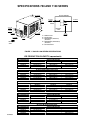
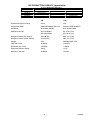
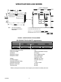
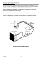
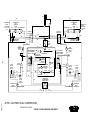
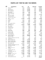
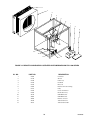
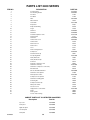
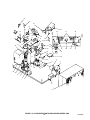
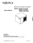
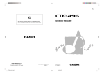
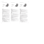
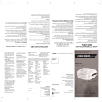
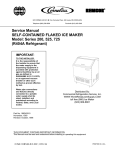
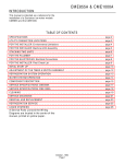
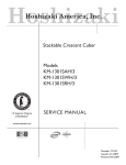
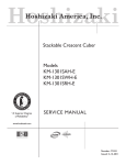
MODULAR FLAKED ICE MAKER Service Manual MODELS: SERIES 750 (R404a), SERIES 1100 (R22), SERIES 2400 (R404a) Part No. 166240009 OCTOBER 1994 Revised October, 1996 THIS DOCUMENT CONTAINS IMPORTANT INFORMATION This Manual must be read and understood before installing or operating this equipment IMI CORNELIUS INC; 10/94 - 10/95 PRINTED IN U.S.A TABLE OF CONTENTS Page INTRODUCTION . . . . . . . . . . . . . . . . . . . . . . . . . . . . . . . . . . . . . . . . . . . . . . . . . . . . . . . . . . . 1 SPECIFICATIONS 750 AND 1100 SERIES . . . . . . . . . . . . . . . . . . . . . . . . . . . . . . . . . . . . 2 SPECIFICATIONS 2400 SERIES . . . . . . . . . . . . . . . . . . . . . . . . . . . . . . . . . . . . . . . . . . . . 4 INSTALLATION INSTRUCTIONS . . . . . . . . . . . . . . . . . . . . . . . . . . . . . . . . . . . . . . . . . . . . 5 REMOTE CONDENSER . . . . . . . . . . . . . . . . . . . . . . . . . . . . . . . . . . . . . . . . . . . . . . . . 6 STACKING INSTRUCTIONS FOR STACKING KIT 29757 . . . . . . . . . . . . . . . . . . . 8 TYPICAL WATER CIRCUIT . . . . . . . . . . . . . . . . . . . . . . . . . . . . . . . . . . . . . . . . . . . . . 9 TYPICAL REFRIGERANT CIRCUIT . . . . . . . . . . . . . . . . . . . . . . . . . . . . . . . . . . . . . . 10 ELECTRICAL CIRCUIT . . . . . . . . . . . . . . . . . . . . . . . . . . . . . . . . . . . . . . . . . . . . . . . . . 11 CIRCUIT DESCRIPTION . . . . . . . . . . . . . . . . . . . . . . . . . . . . . . . . . . . . . . . . . . COMPONENT DESCRIPTION . . . . . . . . . . . . . . . . . . . . . . . . . . . . . . . . . . . . . . . . . . 11 11 BIN THERMOSTAT . . . . . . . . . . . . . . . . . . . . . . . . . . . . . . . . . . . . . . . . . . . . . . . 11 GEARMOTOR START RELAY . . . . . . . . . . . . . . . . . . . . . . . . . . . . . . . . . . . . . 11 POWER RELAY / CONTACTOR . . . . . . . . . . . . . . . . . . . . . . . . . . . . . . . . . . . . 11 GEARMOTOR DELAY THERMOSTAT . . . . . . . . . . . . . . . . . . . . . . . . . . . . . . 11 ON–OFF SWITCH / CIRCUIT BREAKER . . . . . . . . . . . . . . . . . . . . . . . . . . . . 11 FAN CYCLING SWITCH (R404A UNITS) . . . . . . . . . . . . . . . . . . . . . . . . . . . . 11 HIGH PRESSURE CONTROL . . . . . . . . . . . . . . . . . . . . . . . . . . . . . . . . . . . . . . 11 COMPRESSOR START RELAY . . . . . . . . . . . . . . . . . . . . . . . . . . . . . . . . . . . . 12 POTENTIAL RELAYS . . . . . . . . . . . . . . . . . . . . . . . . . . . . . . . . . . . . . . . . . . . . . 12 CAPACITORS – GENERAL . . . . . . . . . . . . . . . . . . . . . . . . . . . . . . . . . . . . . . . . 12 MAINTENANCE . . . . . . . . . . . . . . . . . . . . . . . . . . . . . . . . . . . . . . . . . . . . . . . . . . . . . . . . . . . 20 SANITIZING AND CLEANING PROCEDURE . . . . . . . . . . . . . . . . . . . . . . . . . . . . . . 21 WATER TREATMENT . . . . . . . . . . . . . . . . . . . . . . . . . . . . . . . . . . . . . . . . . . . . . . . . . . 22 WINTER STORAGE . . . . . . . . . . . . . . . . . . . . . . . . . . . . . . . . . . . . . . . . . . . . . . . . . . . 22 CLEANING THE CONDENSER (AIR COOLED) . . . . . . . . . . . . . . . . . . . . . . . . . . . 22 TROUBLESHOOTING . . . . . . . . . . . . . . . . . . . . . . . . . . . . . . . . . . . . . . . . . . . . . . . . . . . . . . 23 UNIT WILL NOT RUN . . . . . . . . . . . . . . . . . . . . . . . . . . . . . . . . . . . . . . . . . . . . . . . . . . 23 COMPRESSOR CYCLES INTERMITTENTLY. . . . . . . . . . . . . . . . . . . . . . . . . . . . . . 23 MAKING WET ICE. . . . . . . . . . . . . . . . . . . . . . . . . . . . . . . . . . . . . . . . . . . . . . . . . . . . . 24 UNIT RUNS BUT MAKES NO ICE. . . . . . . . . . . . . . . . . . . . . . . . . . . . . . . . . . . . . . . . 24 WATER LEAKS. . . . . . . . . . . . . . . . . . . . . . . . . . . . . . . . . . . . . . . . . . . . . . . . . . . . . . . . 24 WATER LEAKS. (CONT’D) . . . . . . . . . . . . . . . . . . . . . . . . . . . . . . . . . . . . . . . . . . . . . . 24 EXCESSIVE NOISE OR CHATTERING. . . . . . . . . . . . . . . . . . . . . . . . . . . . . . . . . . . 24 MACHINE RUNS WITH FULL BIN OF ICE. . . . . . . . . . . . . . . . . . . . . . . . . . . . . . . . 24 UNIT OFF OR TRIPS CIRCUIT BREAKER. . . . . . . . . . . . . . . . . . . . . . . . . . . . . . . . 25 UNIT GOES OFF OR TRIPS CIRCUIT BREAKER. (CONT’D) . . . . . . . . . . . . . . . 26 PARTS LIST FOR 750 AND 1100 SERIES . . . . . . . . . . . . . . . . . . . . . . . . . . . . . . . . . . . . 27 PARTS LIST 2400 SERIES . . . . . . . . . . . . . . . . . . . . . . . . . . . . . . . . . . . . . . . . . . . . . . . . . . 30 WARRANTY . . . . . . . . . . . . . . . . . . . . . . . . . . . . . . . . . . . . . . . . . . . . . . . . . . . . . . . . . . . . . . 32 i 166240009 TABLE OF CONTENTS (cont’d) LIST OF FIGURES Page FIGURE 1. 750 AND 1100 SERIES SPECIFICATIONS . . . . . . . . . . . . . . . . . . . . . 2 FIGURE 2. SPECIFICATIONS FOR 2400 SERIES . . . . . . . . . . . . . . . . . . . . . . . . . 4 FIGURE 3. WATER LEVEL . . . . . . . . . . . . . . . . . . . . . . . . . . . . . . . . . . . . . . . . . . . . . . 7 FIGURE 4. TYPICAL WATER CIRCUIT . . . . . . . . . . . . . . . . . . . . . . . . . . . . . . . . . . . 9 FIGURE 5. TYPICAL REFRIGERANT CIRCUIT . . . . . . . . . . . . . . . . . . . . . . . . . . . 10 FIGURE 6. WIRING DIAGRAM AF/WF–750–MH-R . . . . . . . . . . . . . . . . . . . . . . . . 13 FIGURE 7. WIRING DIAGRAM AF–750–PMH-50R . . . . . . . . . . . . . . . . . . . . . . . . . 14 FIGURE 8. WIRING DIAGRAM AF/WF–1100–MH . . . . . . . . . . . . . . . . . . . . . . . . . . 15 FIGURE 9. WIRING DIAGRAM RF–1100–MH . . . . . . . . . . . . . . . . . . . . . . . . . . . . . 16 FIGURE 10. WIRING DIAGRAM AF/WF–1100–MH–3 . . . . . . . . . . . . . . . . . . . . . . 17 FIGURE 11. WIRING DIAGRAM AF/WF–1100–MH–50 . . . . . . . . . . . . . . . . . . . . . 18 FIGURE 12. WIRING DIAGRAM 2400 SERIES . . . . . . . . . . . . . . . . . . . . . . . . . . . . 19 FIGURE 13. ILLUSTRATED PARTS BREAKDOWN SERIES 750 – 1100 . . . . . . 28 FIGURE 14. REMOTE CONDENSER ILLUSTRATED PARTS BREAKDOWN FOR 1100 SERIES . . . . . . . . . . . . . . . . . . . . . . . . . . . . . . . . . . . . . . . . . . . . . . . . . . . . . 29 FIGURE 15. ILLUSTRATED PARTS BREAKDOWN SERIES 2400 . . . . . . . . . . . 31 LIST OF TABLES AF-750-P-MHR PRODUCTION CHART . . . . . . . . . . . . . . . . . . . . . . . . . . . . . . . . . . . 2 AF-750-P-MH50R PRODUCTION CHART . . . . . . . . . . . . . . . . . . . . . . . . . . . . . . . . 2 WF-750-P-MHR PRODUCTION CHART . . . . . . . . . . . . . . . . . . . . . . . . . . . . . . . . . . 2 AF-1100-P-MH PRODUCTION CHART . . . . . . . . . . . . . . . . . . . . . . . . . . . . . . . . . . . 2 WF-1100-P-MH PRODUCTION CHART . . . . . . . . . . . . . . . . . . . . . . . . . . . . . . . . . . . 2 RF-1100-P-MH PRODUCTION CHART . . . . . . . . . . . . . . . . . . . . . . . . . . . . . . . . . . . 3 AF-2400-P-MHR PRODUCTION CHART . . . . . . . . . . . . . . . . . . . . . . . . . . . . . . . . . . 4 166240009 ii INTRODUCTION We have strived to produce a quality product. The design has been kept simple thus insuring trouble–free operation. This manual has been prepared to assist servicemen and users with information concerning installation, construction and maintenance of the ice making equipment. The problems of the serviceman and user have been given special attention in the development and engineering of our ice makers. If you encounter a problem which is not covered in this manual, please feel free to write or call. We will be happy to assist you in any way we can. When writing, please state the model and serial number of the machine. Address all correspondence to: A Product of IMI Cornelius Inc. One Cornelius Place Anoka, MN 55303–1592 Phone 800–554–3526 FAX 612–422–3232 PRINTED IN USA 1 166240009 SPECIFICATIONS 750 AND 1100 SERIES 23 1/8-IN. 59-CM CHUTE OPENING 8 1/4-IN. 21-CM 23-IN. 58-CM 1 1/2-IN. 4-CM 1 3/4-IN. 4-CM 1 1/2-IN. 4-CM A 5-IN. 13-CM FRONT BOTTOM VIEW B C D E 11 1/2-IN. 29-CM 5 1/16-IN. 13-CM 26 1/4-IN. 67-CM 2-IN. 5-CM REAR VIEW A = POWER INLET B = WATER INLET C = CONDENSER (WATER IN) (WC ONLY) D = CONDENSER (WATER OUT) (WC ONLY) E = CHASSIS DRAIN 9-IN. 23-CM FIGURE 1. 750 AND 1100 SERIES SPECIFICATIONS ÁÁÁÁÁÁÁÁÁÁÁÁÁÁÁÁÁÁÁÁÁÁÁÁÁÁÁÁ ÁÁÁÁÁÁÁ ÁÁÁÁÁÁÁÁÁÁÁÁÁÁÁÁÁÁÁÁÁÁ ÁÁÁÁÁÁÁÁÁÁÁÁÁÁÁÁÁÁÁÁÁÁÁÁÁÁÁÁ ÁÁÁÁÁÁÁÁÁÁÁÁÁÁÁÁÁÁÁÁÁÁ ÁÁÁÁÁÁÁ ÁÁÁÁÁÁÁÁ ÁÁÁÁÁÁÁÁ ÁÁÁÁÁÁÁÁ ÁÁÁÁÁÁÁ ÁÁÁÁÁÁÁÁ ÁÁÁÁÁÁÁÁ ÁÁÁÁÁÁÁÁ ÁÁÁÁÁÁÁ ÁÁÁÁÁÁÁÁ ÁÁÁÁÁÁÁÁ ÁÁÁÁÁÁÁÁ ÁÁÁÁÁÁÁ ÁÁÁÁÁÁÁÁ ÁÁÁÁÁÁÁÁ ÁÁÁÁÁÁÁÁ ÁÁÁÁÁÁÁÁÁÁÁÁÁÁÁÁÁÁÁÁÁÁÁÁÁÁÁÁ ÁÁÁÁÁÁÁ ÁÁÁÁÁÁÁÁÁÁÁÁÁÁÁÁÁÁÁÁÁÁ ÁÁÁÁÁÁÁÁÁÁÁÁÁÁÁÁÁÁÁÁÁÁÁÁÁÁÁÁ ÁÁÁÁÁÁÁÁÁÁÁÁÁÁÁÁÁÁÁÁÁÁ ÁÁÁÁÁÁÁ ÁÁÁÁÁÁÁÁ ÁÁÁÁÁÁÁÁ ÁÁÁÁÁÁÁÁ ÁÁÁÁÁÁÁ ÁÁÁÁÁÁÁÁ ÁÁÁÁÁÁÁÁ ÁÁÁÁÁÁÁÁ ÁÁÁÁÁÁÁ ÁÁÁÁÁÁÁÁ ÁÁÁÁÁÁÁÁ ÁÁÁÁÁÁÁÁ ÁÁÁÁÁÁÁ ÁÁÁÁÁÁÁÁ ÁÁÁÁÁÁÁÁ ÁÁÁÁÁÁÁÁ ÁÁÁÁÁÁÁÁÁÁÁÁÁÁÁÁÁÁÁÁÁÁÁÁÁÁÁÁ ÁÁÁÁÁÁÁ ÁÁÁÁÁÁÁÁÁÁÁÁÁÁÁÁÁÁÁÁÁÁ ÁÁÁÁÁÁÁÁÁÁÁÁÁÁÁÁÁÁÁÁÁÁÁÁÁÁÁÁ ÁÁÁÁÁÁÁ ÁÁÁÁÁÁÁÁ ÁÁÁÁÁÁÁÁ ÁÁÁÁÁÁÁÁ ÁÁÁÁÁÁÁÁÁÁÁÁÁÁÁÁÁÁÁÁÁÁ ÁÁÁÁÁÁÁ ÁÁÁÁÁÁÁÁ ÁÁÁÁÁÁÁÁ ÁÁÁÁÁÁÁÁ ÁÁÁÁÁÁÁ ÁÁÁÁÁÁÁÁ ÁÁÁÁÁÁÁÁ ÁÁÁÁÁÁÁÁ ÁÁÁÁÁÁÁ ÁÁÁÁÁÁÁÁÁÁÁÁÁÁÁÁÁÁÁÁÁÁÁÁÁÁÁÁ ÁÁÁÁÁÁÁÁ ÁÁÁÁÁÁÁÁ ÁÁÁÁÁÁÁÁ ÁÁÁÁÁÁÁÁÁÁÁÁÁÁÁÁÁÁÁÁÁÁÁÁÁÁÁÁ ÁÁÁÁÁÁÁ ÁÁÁÁÁÁÁÁÁÁÁÁÁÁÁÁÁÁÁÁÁÁ ÁÁÁÁÁÁÁ ÁÁÁÁÁÁÁÁÁÁÁÁÁÁÁÁÁÁÁÁÁÁ ÁÁÁÁÁÁÁÁ ÁÁÁÁÁÁÁÁ ÁÁÁÁÁÁÁÁ ÁÁÁÁÁÁÁ ÁÁÁÁÁÁÁÁ ÁÁÁÁÁÁÁÁ ÁÁÁÁÁÁÁÁ ÁÁÁÁÁÁÁÁ ÁÁÁÁÁÁÁ ÁÁÁÁÁÁÁÁ ÁÁÁÁÁÁÁÁ ÁÁÁÁÁÁÁÁ ÁÁÁÁÁÁÁ ÁÁÁÁÁÁÁÁ ÁÁÁÁÁÁÁÁ ÁÁÁÁÁÁÁÁ ÁÁÁÁÁÁÁÁÁÁÁÁÁÁÁÁÁÁÁÁÁÁÁÁÁÁÁÁ ÁÁÁÁÁÁÁ ÁÁÁÁÁÁÁÁÁÁÁÁÁÁÁÁÁÁÁÁÁÁ ÁÁÁÁÁÁÁÁÁÁÁÁÁÁÁÁÁÁÁÁÁÁÁÁÁÁÁÁ ÁÁÁÁÁÁÁÁÁÁÁÁÁÁÁÁÁÁÁÁÁÁ ÁÁÁÁÁÁÁ ÁÁÁÁÁÁÁÁ ÁÁÁÁÁÁÁÁ ÁÁÁÁÁÁÁÁ ÁÁÁÁÁÁÁ ÁÁÁÁÁÁÁÁ ÁÁÁÁÁÁÁÁ Á ÁÁÁÁÁÁÁÁ ÁÁÁÁÁÁÁ ÁÁÁÁÁÁÁ ÁÁÁÁÁÁÁÁ ÁÁÁÁÁÁÁÁ ÁÁÁÁÁÁÁÁ ÁÁÁÁÁÁÁ ÁÁÁÁÁÁÁÁ ÁÁÁÁÁÁÁÁ ÁÁÁÁÁÁÁÁ ICE PRODUCTION CAPACITY (approximate) AIR TEMPERATURE 50°F/10°C 70°F/21°C 90°F/32°C AIR TEMPERATURE 50°F/10°C 70°F/21°C 90°F/32°C AIR TEMPERATURE 50°F/10°C 70°F/21°C 90°F/32°C AIR TEMPERATURE 70°F/21°C 80°F/27°C 90°F/32°C AIR TEMPERATURE 70°F/21°C 80°F/27°C 90°F/32°C 166240009 AF-750-P-MHR PRODUCTION CHART WATER TEMPERATURE 50°F/10°C 70°F/21°C 873 lbs/397 kgs 745 lbs/339 kgs 869 lbs/395 kgs 738 lbs/335 kgs 755 lbs/343 kgs 662 lbs/301 kgs 80°F/27°C 695 lbs/316 kgs 688 lbs/313 kgs 609 lbs/277 kgs AF-750-P-MH50R PRODUCTION CHART WATER TEMPERATURE 50°F/10°C 70°F/21°C 748 lbs/340 kgs 643 lbs/292 kgs 739 lbs/336 kgs 635 lbs/289 kgs 678 lbs/308 kgs 586 lbs/266 kgs 80°F/27°C 595 lbs/279 kgs 585 lbs/266 kgs 542 lbs/246 kgs WF-750-P-MHR PRODUCTION CHART WATER TEMPERATURE 50°F/10°C 70°F/21°C 765 lbs/348 kgs 643 lbs/292 kgs 748 lbs/340 kgs 631 lbs/287 kgs 730 lbs/332 kgs 621 lbs/282 kgs 80°F/27°C 587 lbs/267 kgs 585 lbs/266 kgs 582 lbs/265 kgs AF-1100-P-MH PRODUCTION CHART WATER TEMPERATURE 50°F/10°C 60°F/16°C 1202 lbs/545 kgs 1119 lbs/508 kgs 70°F/21°C 988 lbs/448 kgs WF-1100-P-MH PRODUCTION CHART WATER TEMPERATURE 50°F/10°C 60°F/16°C 1151 lbs/523 kgs 1123 lbs/509 kgs 70°F/21°C 1060 lbs/467 kgs 2 ÁÁÁÁÁÁÁÁÁÁÁÁÁÁÁÁÁÁÁÁÁÁÁÁÁÁÁÁ ÁÁÁÁÁÁ ÁÁÁÁÁÁÁÁÁÁÁÁÁÁÁÁÁÁÁÁÁÁ ÁÁÁÁÁÁÁÁ ÁÁÁÁÁÁÁÁ ÁÁÁÁÁÁÁÁ ÁÁÁÁÁÁÁÁÁÁÁÁÁÁÁÁÁÁÁÁÁÁÁÁÁÁÁÁ ÁÁÁÁÁÁÁÁÁÁÁÁÁÁ ÁÁÁÁÁÁÁÁ ÁÁÁÁÁÁÁÁ ÁÁÁÁÁÁÁÁ ÁÁÁÁÁÁ ÁÁÁÁÁÁÁÁ ÁÁÁÁÁÁÁÁ ÁÁÁÁÁÁÁÁ ÁÁÁÁÁÁÁÁÁÁÁÁÁÁ ÁÁÁÁÁÁÁÁ ÁÁÁÁÁÁÁÁ ICE PRODUCTION CAPACITY (approximate) AIR TEMPERATURE 70°F/21°C 80°F/27°C 90°F/32°C RF-1100-P-MH PRODUCTION CHART WATER TEMPERATURE 50°F/10°C 60°F/16°C 1202 lbs/545 kgs 1119 lbs/508 kgs 70°F/21°C 988 lbs/448 kgs 750 1100 Compressor Electrical Rating 3/4 hp 2 hp Compressor Model Copeland RS64CIE-PAF-214 Copeland CRD-10200PFV Condenser Air or Water Cooled Air or Water Cooled Refrigerant Charge AC–21oz R404a AC–25 oz R–22 WC–18oz R404a WC–23 oz R–22 Refrigerant Control (Air Cooled) AXV (30 PSI) AXV (15-17 PSI) Refrigerant Control (Water Cooled) AXV (28 PSI) AXV (15-17 PSI) Voltage 115V 208/230V 60HZ 1PH Total Amp. Draw 16 AMPS 12 AMPS Gearmotor Amp. Draw 1.6 AMPS .7 AMPS Gearmotor Electrical Rating 1/8 hp 1/7 hp Maximum Fuse Size 20 AMPS 15 amps 3 166240009 SPECIFICATIONS 2400 SERIES 17 1/2-IN. 44-CM OVERALL DIMENSIONS 23-9/16-IN. HIGH x 45-1/8-IN. WIDE x 27-5/16-IN. DEEP 60-CM 115-CM 69-CM 8-IN. 20-CM 15 1/8-IN. 38-CM 44-IN. 112-CM 14 1/4-IN. 36-CM 15 1/8-IN. 38-CM ELECTRICAL WATER OUT (W/C) AIR IN 44-IN. 112-CM NOTE: CONDENSER SIDE WATER IN (W/C) WATER INLET 23 1/2-IN. 60-CM 9 1/8-IN. 23-CM A B 8 3/4-IN. 22-CM 27-IN. 69-CM 9 1/8-IN. 23-CM ”A”- ALTERNATE ICE DROP AREA FOR TOP UNIT WHEN TWO ARE STACKED. AIR IS EXHAUSTED OUT BACK AND SIDE OPPOSITE CONDENSER ”B”-ICE DROP AREA FOR BASIC UNIT. INDIVIDUAL ”A” & ”B” DIMENSIONS ARE 5-5/32-IN. x 8-9/32-IN. 13-CM 21-CM RECOMMENDED BIN TOP CUT OUT AS SHOWN ABOVE 14-1/4-IN. x 8-3/4-IN. 22-CM 36-CM FIGURE 2. SPECIFICATIONS FOR 2400 SERIES ÁÁÁÁÁÁÁÁÁÁÁÁÁÁÁÁÁÁÁÁÁÁÁÁÁÁÁÁ ÁÁÁÁÁÁÁÁÁÁÁÁÁÁÁÁÁÁÁÁÁÁÁÁÁÁÁÁ ÁÁÁÁÁÁÁ ÁÁÁÁÁÁÁÁÁÁÁÁÁÁÁÁÁÁÁÁÁÁ ÁÁÁÁÁÁÁÁ ÁÁÁÁÁÁÁÁ ÁÁÁÁÁÁÁÁ ÁÁÁÁÁÁÁ ÁÁÁÁÁÁÁÁ ÁÁÁÁÁÁÁÁ ÁÁÁÁÁÁÁÁ ÁÁÁÁÁÁÁ ÁÁÁÁÁÁÁÁ ÁÁÁÁÁÁÁÁ ÁÁÁÁÁÁÁÁ ÁÁÁÁÁÁÁ ÁÁÁÁÁÁÁÁ ÁÁÁÁÁÁÁÁ ÁÁÁÁÁÁÁÁ ICE PRODUCTION CAPACITY (approximate) AIR TEMPERATURE 50°F/10°C 70°F/21°C 90°F/32°C AF-2400-P-MHR PRODUCTION CHART WATER TEMPERATURE 50°F/10°C 70°F/21°C 2507 lbs/1140 kgs 2175 lbs/989 kgs 2495 lbs/1134 kgs 2045 lbs/930 kgs 2095 lbs/952 kgs 1800 lbs/818 kgs Compressor Electrical Rating Compressor Model Condenser Refrigerant Charge Refrigerant Control 80°F/27°C 2008 lbs/913 kgs 1850 lbs/841 kgs 1680 lbs/764 kgs 2 hp Copeland CS14K6E-PFV-235 Air Cooled 26 oz R404a/each side AXV 26-PSI factory setting/Each Side 208/230 1 ph. 60 hz. 3/8” SAE male flare 1/7 hp .7 amps at 230V 40 amps 30 amps Voltage Inlet Water Supply Gearmotor Electrical Rating Gearmotor Amp Draw Mamimum Fuse Size Total Amp Draw Refer to serial plate for maximum circuit ampacity and minimum time delay fuse size. 166240009 4 INSTALLATION INSTRUCTIONS You will get better service from the ice machine, longer life and greater convenience if you choose its location with care. Here are a few points to consider: 1. Select a location as close as possible to where you are going to use the ice. 2. Allow a minimum of 6” space at sides and rear of machine for ventilation. 3. A kitchen installation is not desirable as a rule. If a kitchen installation is necessary, locate the machine as far away from the cooking area as possible. Grease laden air will form a greasy deposit on the condenser. This reduces the ice making efficiency and necessitates thorough cleaning quite often. 4. If you install the unit in a storeroom, be sure the room is well ventilated. NOTE: Do not install where the ambient and incoming water temperature will drop below 50° F rise to over 100° F. WARNING: If water pressure exceeds 50 pounds, a water pressure regulator should be installed in water inlet line between water shut–off valve and strainer. Minimum incoming water pressure required is 22 pounds. 5. Uncrate the unit by removing the staples or nails from the bottom of the carton and lift off. 6. Remove the bolts holding the skid to the machine. 7. For units supplied with a bin sealing gasket, cement the gasket to the bottom outside edge of the machine before it is set on the bin. NOTE: This is an N.S.F. requirement and must be done by the installer. 8. Make sure the correct bin adapter has been supplied when used. Then mount the unit on the bin and level both properly. 9. For units not supplied with bin sealing gasket, seal the machine to bin with an N.S.F. approved sealant such as Dow R.T.V. #732, 734, or G.E. #102, 108. This is an N.S.F. requirement and is the responsibility of the installer. 10. The incoming water for the ice making section requires a 3/8” copper line. Connect this water line to the 3/8” male flare fitting on the back of the unit. NOTE: For water cooled units, a separate 3/8” copper water line is required to be connected to the flare fitting on the back of the unit marked condenser water in. A 3/8” flare connected line will have to be provided from the fitting marked condenser water out to the drain. A water regulating valve installed at the factory was set to maintain 270 to 310 PSI head pressure for R–404a units and 210 to 225 PSI for R–22 units (Approx. 105_ to 110_F). Check temperatures at condenser outlet and adjust if necessary. 11. Connect a drain hose to the condensate drain stub tube. NOTE: All plumbing must be done in accordance with national and local codes. 12. Bring the electrical supply into the unit through a handy box located on the back of unit and make connections. NOTE: NOTE: Make sure the proper voltage and number of wires are provided. See serial plate and make connections. NOTE: All wiring must conform to national and local codes. 13. Turn on water supply and observe water level in evaporator sections. Water level is to be maintained at the top of the evaporator. (See adjustment procedure) 5 166240009 14. Turn machine on and check for proper voltage and amp draw on the entire unit as well as components such as the gearmotor and fan motor. 15. Check refrigerant circuit and all plumbing connections for leaks, etc. 16. Check bin thermostat or mechanical shut–off for proper operations. In the mid–range the bin thermostat will open at 42° and has a 6° differential. REMOTE CONDENSER Remote condensers should be installed above the ice machine and in a level configuration. They are connected to the ice making unit by copper tubing and line valves. The female half of the line valve is mounted on the ice making unit and the remote condenser. The male half is soldered on the tube ends when tubing kits are provided with the machine. If tubing kits are not provided, the male half of the line valves will be provided in a valve kit and the installer will mount them on the tubing he provides. NOTE: WHEN VERTICAL LINES ARE INVOLVED IN THE INSTALLATION, FOLLOW STANDARD REFRIGERATION PRACTICES FOR VERTICAL LINES TO ASSURE POSITIVE OIL RETURN TO THE COMPRESSOR. VERTICAL LIFT TO BE NO MORE THAN 15 FEET. NOTE: WE DO NOT RECOMMEND TUBING RUNS OF MORE THAN 40 FEET.. NOTE: The seals for the line valves will be found in an envelope on the remote condenser. Make sure they are used. NOTE: REMOVE CAP PLUGS FROM ALL LINE VALVES BEFORE MAKING VALVE CONNECTIONS WITH THE SEAL. NOTE: A LOW VOLTAGE ELECTRICAL CONTROL CIRCUIT MUST BE FIELD WIRED BETWEEN THE ICE MACHINE AND THE REMOTE CONDENSER RELAY. THOSE WIRES SHOULD BE RUN WITH THE TUBING DURING INSTALLATION. REFER TO APPLICABLE WIRING DIAGRAMS. NOTE: When the line valves are connected to each other the refrigerant circuit is complete. Each valve half has its own shut-off which must be fully opened to allow the refrigerant to flow though the system before it is started. The ice making unit utilizing a remote condenser is shipped from the factory with the receiver holding the refrigerant charge. Additional refrigerant may be required upon installation depending upon the ambient conditions the remote condenser is operating under, the condenser and line sizing. A three way head pressure control valve is used to maintain a relatively consistent head pressure between 175 and 185 PSI for R22 in the receiver in cold ambient conditions. Because of this valve some liquid refrigerant will be held in the condenser. NOTE: THE HEAD PRESSURE CONTROL VALVE WILL NOT OPERATE CORRECTLY WHEN A TOTAL PRESSURE DROP OF 14 POUNDS OR MORE IS CREATED BETWEEN THE ICE MAKING UNIT, THROUGH THE TUBING TO THE REMOTE CONDENSER, THE CONDENSER AND THE RETURN TUBING TO THE ICE MAKING UNIT. The remote condenser requires a separate power supply from the ice making unit. Refer to the remote condenser wiring diagram. 166240009 6 WARNING: WATER LEVEL MUST BE MAINTAINED AT THE TOP OF THE EVAPORATOR. WATER LEVEL ill224 FIGURE 3. WATER LEVEL 1. Remove gearmotor and auger. 2. Adjust float valve to get water level to top seam of the evaporator. 3. Re–install auger. WATER LEVEL WILL RISE WHEN AUGER IS INSERTED BUT WHEN THE MACHINE IS TURNED BACK ON AND ICE STARTS BEING MADE, THE WATER LEVEL WILL GO BACK TO THE ORIGINAL SETTING. 4. Re–install gearmotor assembly and start machine. 7 166240009 STACKING INSTRUCTIONS FOR STACKING KIT 29757 The Kit consists of: 1 – #26102 Sealer 2 – #261 1/4-20x5/8 screw 2 – #256 1/4” flat washer 2 – #239 1/4” Lock Washer 1 – #29758 Stacking Chute Extension 1. After uncrating machine to be stacked, remove front and rear panels. 2. Remove top and front panels of bottom machine. 3. Remove alternate chute opening cover from bottom machine. 4. Insert vertical chute extension from kit into alternate chute opening of bottom unit and seal it to the base with sealer provided in the kit. 5. Carefully mount stacking unit reversed 180° with the compressor and condenser opposite those of the bottom unit. NOTE: When mounting, make sure stacking unit vertical chute aligns and inserts correctly with chute extension installed in alternate chute opening of bottom unit. Raise chute bracket to cover opening and tighten bracket screws. 6. Secure both machines together as shown in the illustration utilizing screws and washers provided in the kit. 7. After stacking unit, hook up electrical and water. NOTE: The two units must operate independently of each other. 8. Connect drain line from tee under the stacked unit to run out of the back of the unit. 9. Replace panels of stacked unit front to front and back to back as the machine is mounted. Replace front panel of bottom unit. 166240009 8 TYPICAL WATER CIRCUIT The supply water enters the float chamber through a small orifice. The water level rises and lifts the buoyant float with it. The float attached to the float arm seats a valve to shut off any further water supply. As water leaves the float chamber, the level drops along with the float and arm, causing the valve to open and admit more water. Thus the water level is maintained automatically as the machine operates. Water now flows through a hose connected to the float chamber and enters the opening of the evaporator shell. The water level in the shell will rise to the same level that is maintained in the float chamber. The water that is in immediate contact with the center post evaporator will be reduced in temperature. As a result, freezing occurs and ice forms on the surface of the evaporator. As more water is frozen, the thickness of the ice increases until it exceeds the distance allowed between the evaporator and auger. The auger rotates at a slow speed to wipe off the accumulated ice as well as help it to the surface. After the ice reaches the surface it is discharged through the top opening in the shell. An ice chute attached to the shell conveys the ice to the storage bin where it accumulates in the insulated bin until it is used. The ice will pile up to a point where the bin thermostat tubing is located. When the ice touches this brass tubing, the unit will shut–off and remain off until enough ice is used or melted to reduce the pile. Any ice that melts will pass through the drain and drain hose to an open drain. WATER IN ICE OUT FLOAT CHAMBER EVAPORATOR CHAMBER FIGURE 4. TYPICAL WATER CIRCUIT 9 166240009 TYPICAL REFRIGERANT CIRCUIT Heat always flows from hot to cold and therefore, the ”heat load” supplied to the evaporator section by water gives up its heat to the refrigerant which is at a temperature below the freezing point of water. This refrigerant now passes through the heat exchanger back to the compressor, as a low pressure vapor. This low pressure vapor is compressed in the compressor, as it leaves the compressor at a high pressure in vapor form it enters the top of the condenser. The condenser has a rapid flow of cool air across it which removes much of the heat from the hot refrigerant vapor. As the vapor, passing through the condenser, loses heat it condenses back to a liquid since it is still under high pressure and cooler than when it entered the condenser. The liquid refrigerant then passes through the drier/filter still under pressure and goes through the heat exchanger where further cooling takes place. As the refrigerant leaves the automatic expansion valve, the pressure has dropped, causing the refrigerant to vaporize and boil off as it picks up heat in the evaporator and since the pressure is low, the refrigerant will be cold. AXV HEAT EXCHANGER EVAPORATOR COMPRESSOR CONDENSER DRIER/FILTER FIGURE 5. TYPICAL REFRIGERANT CIRCUIT 166240009 10 ELECTRICAL CIRCUIT CIRCUIT DESCRIPTION As the manual on–off–circuit breaker switch is pushed to ”on”, an electrical circuit is completed to the gearmotor via the circuit breaker gearmotor overload, power relay / contactor, gearmotor delay thermostat and the bin thermostat. After the previous circuit has been completed the condenser fan motor will start as will the compressor (via the high pressure control and the compressor starting relay). COMPONENT DESCRIPTION BIN THERMOSTAT This is electrically in ”series” with the ice making system. when the bin is full, the contact opens, terminating power to the machine. GEARMOTOR START RELAY This is a current type relay which means as the gearmotor run winding comes ”on” the line, the current draw initially is relatively heavy through the relay coil (coil is in series with run winding). It then acts like a normal relay and the N.O. start contact ”makes”, completing a circuit through the start capacitor to the start winding. As the gearmotor picks up speed, the amp draw through the relay coil drops off allowing the armature to return to its normal position (start contact ”opens”). This action removes the start winding from the circuit. POWER RELAY / CONTACTOR This relay controls the compressor power only. GEARMOTOR DELAY THERMOSTAT This thermostat keeps the gearmotor running until the suction line temperature reaches 45_ after the full bin switch terminates power to the power relay / contactor. ON–OFF SWITCH / CIRCUIT BREAKER This switch interrupts power to the entire unit. The switch has a circuit breaker incorporated into its’ design. This circuit breaker will trip out in the event the gearmotor draws to high of amps In such an event the power is interrupted to the unit. To reset the circuit breaker and reestablish power to the unit, push the switch to the ”off” position and then back to the ”on” position. FAN CYCLING SWITCH (R404a Units) The function of this switch is to maintain condensing pressures at a satisfactory level during–low ambient conditions. The switch breaks the circuit to the condenser fan motor at 205 PSI and makes the circuit at 275 PSI. HIGH PRESSURE CONTROL The high pressure cut out is electrically in series with the power relay. As the head pressure rises to 450 PSIG for R404a charged units and 400 PSIG for R 22 charged units, a preset level, the contact opens thus breaking the circuit to the compressor via the power relay contactor. This control must be reset manually on R404a units. 11 166240009 COMPRESSOR START RELAY This is a current type relay and contains a N.O. contact which is connected in series with the start winding of the compressor. The relay coil is electrically in series with the run winding. When power is applied, the compressor draws high current which sets up a magnetic field around the magnet coil which causes the relay to operate, closing the relay contact. As the compressor approaches operating speed, the current flowing through the coil decreases, permitting the relay contact to open, thereby opening the starting circuit. POTENTIAL RELAYS The potential relay is used as a compressor starting relay, The contact in the potential relay is N.C.. The magnet coil is connected across (parallel) the start winding and is affected by induced voltage, generated by the start winding. As the compressor comes up to design speed, the voltage across the relay coil increases and at running speed is sometimes as much as 2 1/2 times the supply voltage. This voltage sets up a magnetic field which causes the relay to operate. The starting relay is calibrated to remove the start capacitor (open the starting circuit) at approximately 85% of the motor design speed. NOTE: BOTH TYPES OF RELAYS ARE DESIGNED TO OPERATE WITHIN VERY NARROW LIMITS OF VOLTAGE AND CURRENT DICTATED BY MOTOR DESIGN, THEREFORE, WHEN MAKING A REPLACEMENT OF A RELAY ALWAYS PROVIDE AN EXACT REPLACEMENT, RECOMMENDED BY THE COMPRESSOR MANUFACTURER. CAPACITORS – GENERAL An electrical capacitor is a device which stores up electrical energy. Capacitors are used with single phase motors to provide starting torque and improve running characteristics; by feeding this energy to the start winding in step with the run winding. Any capacitor has three (3) essential parts, two (2) of which are usually foil plates separated and insulated by the third part called the dielectric. Two general types of capacitors are used with electric motors. The electrolytic starting capacitor usually uses a very thin film of oxide on the metallic plate as the dielectric. The running capacitor usually is of the liquid filled type. 166240009 12 YL BL BL OUTLET BOX YL ON-OFF SWITCH CIRCUIT BREAKER RATED 2.0 AMPS GR BL BK BL BL WH WH YL BL BIN THERMOSTAT DELAY THERMOSTAT BL GEAR MOTOR START CAPACITOR 64-77 MFD 165 VAC RD RD 3 BK 2 4 RD RD GEAR MOTOR START RELAY GEAR MOTOR YL M WH FAN MOTOR BK BL CONTROL HIGH PRESSURE BK LOW AMBIENT SWITCH (A/C ONLY) COMPRESSOR OVERLOAD BL WH BK COMPRESSOR C 1 BL WH BK M BK COMPRESSOR START CAPACITOR 72-86 MFD 330 VAC RD WH R S YL YL COMPRESSOR RUN CAPACITOR 30 MFD 440 VAC CONTACTOR OR 1 2 WH 5 COMPRESSOR START RELAY AF/WF-750-MH-R 115 VOLTS 60 Hz FIGURE 6. WIRING DIAGRAM AF/WF–750–MH-R 13 166240009 YL BL OUTLET BOX ON-OFF SWITCH CIRCUIT BREAKER RATED 1.5 AMPS BL GN/Y RD LB BK BR BL YL BL BIN THERMOSTAT DELAY THERMOSTAT GEAR MOTOR START RELAY 3 BK 2 RD 4 RD BL YL GEAR MOTOR GEAR MOTOR START CAPACITOR RD RD M YL GN/Y RD FAN MOTOR BK BL BK FAN SWITCH CONTROL HIGH PRESSURE COMPRESSOR OVERLOAD COMPRESSOR 1 BL RD BK RD BR BK RD LB CONTACTOR S RD COMPRESSOR START CAPACITOR 88-106 MFD 220 V YL GN/Y BL L COMPRESSOR START RELAY AF750PMH-50-R 220 VOLTS 50 Hz 166240009 GN/Y R C BK M WIRE NUT FIGURE 7. WIRING DIAGRAM AF–750–PMH-50R 14 S M RD YL BL OUTLET BOX ON-OFF SWITCH CIRCUIT BREAKER RATED 1.5 AMPS GR BL RD BK BL RD YL BK BL BIN THERMOSTAT DELAY THERMOSTAT BK 4 BK M BL 3 RD RD 2 GEAR MOTOR START GEAR CAPACITOR MOTOR RD RD FAN MOTOR A/C ONLY GEAR MOTOR START RELAY BK RD YL BK M BK EVAPORATOR HEATER RD RD CONTROL HIGH PRESSURE (W/C ONLY) RD BK RD COMPRESSOR COMPRESSOR RUN CAPACITOR RD COMPRESSOR START CAPACITOR RD R BK C BK RD BK RD POWER RELAY S YL YL OR BK COMPRESSOR START RELAY 2 5 RD 1 AF/WF-1100-MH 208/230 VOLTS 60 Hz FIGURE 8. WIRING DIAGRAM AF/WF–1100–MH 15 166240009 YL BL OUTLET BOX GW ON-OFF SWITCH CIRCUIT BREAKER RATED 1.5 AMPS BL RD BK BL RD YL BK GEAR MOTOR BL BIN THERMOSTAT START RELAY DELAY THERMOSTAT 3 BK 2 RD 4 RD BL GEAR MOTOR START CAPACITOR RD RD M 24V FIELD WIRING RD CONTROL HIGH PRESSURE 230V REMOTE CONDENSER RD BK BK RD BK COMPRESSOR BK R RD C BK RD CRANKCASE HEATER CONTACTOR S RD M YL BK COOLING FAN MOTOR BK WH POWER RELAY CLASS II TRANSFORMER FAN MOTOR M YL RD COMPRESSOR START CAPACITOR COMPRESSOR RUN CAPACITOR RD YL BK 1 5 COMPRESSOR START RELAY RF-1100-MH 208/230 VOLTS 60 Hz 166240009 RD GEAR MOTOR FIGURE 9. WIRING DIAGRAM RF–1100–MH 16 2 OR RD YL BL OUTLET BOX GR ON-OFF SWITCH CIRCUIT BREAKER RATED 1.5 AMPS BL RD BK BL RD BL YL BK GEAR MOTOR BL BIN THERMOSTAT START RELAY DELAY THERMOSTAT 3 BK 2 RD RD 4 BL GEAR MOTOR START CAPACITOR RD RD GEAR MOTOR M RD YL RD FAN MOTOR M BK RD CONTROL HIGH PRESSURE (W/C ONLY) BL RD BK RD BK BK RD BK RD BL COMPRESSOR M CONTACTOR AF/WF-1100-MH-3 3 PHASE 208/230 VOLTS 60 Hz FIGURE 10. WIRING DIAGRAM AF/WF–1100–MH–3 17 166240009 YL BL OUTLET BOX GW ON-OFF SWITCH CIRCUIT BREAKER RATED 1.5 AMPS BL RD BK BL LB YL BR BL BIN THERMOSTAT DELAY THERMOSTAT GEAR MOTOR START RELAY 3 BK 2 RD 4 RD BL GEAR MOTOR START CAPACITOR RD RD GEAR MOTOR M RD YL RD FAN MOTOR M BK RD CONTROL HIGH PRESSURE (W/C ONLY) LB COMPRESSOR BR COMPRESSOR RUN CAPACITOR RD RD YL YL R C RD BK BK RD CONTACTOR S BK RD OR BK 1 5 COMPRESSOR START RELAY AF/WF-1100-MH-50 240 VOLTS 50 Hz 166240009 COMPRESSOR START CAPACITOR FIGURE 11. WIRING DIAGRAM AF/WF–1100–MH–50 18 2 RD RD RD RD BK COMPRESSOR RUN CAPACITOR 35 MFD 370V RD COMPRESSOR RD COMPRESSOR START CAPACITOR 145-174 MFD 250V GW COMPRESSOR YL WH 5 C S BK RD YL MAIN ON-OFF SWITCH RD ON-OFF SWITCH CIRCUIT BREAKER RATED 1.5 AMPS YL YL BK YL 19 2 RD RD GEAR MOTOR DELAY THERMOSTAT BL BL RD BL BK 4 BK WH 2 COMPRESSOR START RELAY GEAR MOTOR START CAPACITOR YL OR BK ON-OFF SWITCH CIRCUIT BREAKER RATED 1.5 AMPS BIN THERMOSTAT LOW WATER BK PRESSURE SWITCH CI 20 CO 10 M COND. FAN SYSTEM 1 LOW AMBIENT PRESSURE SWITCHES WH BK CI 275 CO 205 BK A/C BK ONLY BK SYSTEM 2 YL BL YL YL GEAR MOTOR BK BL BK M GEAR MOTOR START RD CAPACITOR RD GEAR MOTOR START RELAY 4 BL 3 BL RD YL 1 4 3 6 1 HIGH PRESSURE SWITCH CO 450 GEAR MOTOR & COMPRESSOR CONTROL RELAY OR 5 BL RD BIN LIMIT THERMOSTAT M BL 3 RD YL BK BK HIGH PRESSURE SWITCH CO 450 BL GEAR MOTOR YL S BK RD BL GEAR MOTOR START RELAY C SYSTEM 2 CONTACTOR BK COMPRESSOR START RELAY 1 SYSTEM 1 CONTACTOR BK 2 COMPRESSOR START CAPACITOR 145-174 MFD 250V R R YL COMPRESSOR RUN CAPACITOR 35 MFD 370V RD RD 2 BK BL RD YL 166240009 AF/WF-2400 PMHR DUAL COMPRESSORS 208/230 VOLTS 1 PHASE FIGURE 12. WIRING DIAGRAM 2400 SERIES GEAR MOTOR DELAY THERMOSTAT MAINTENANCE THE FOLLOWING MAINTENANCE SHOULD BE PERFORMED AT LEAST EVERY SIX MONTHS ON FLAKED ICE MACHINES: 1. Check power supply with machine running for proper voltage. 2. Check water level in the float tank reservoir. Water level should be maintained at the top of the evaporator. Adjust if necessary. (See illustration and adjustment procedure) 3. Clean the air–cooled condenser coil with a stiff brush or vacuum cleaner (See procedure) CAUTION: CONDENSER COOLING FINS ARE SHARP, USE CARE WHEN CLEANING. 4. Clean the ice storage bin and flush the bin drain at least once a month. 5. If a water conditioner is installed in the inlet water line, change, replace, or clean the filter, strainer or cartridge as required. 6. If heavy mineral deposits on the auger and evaporator shell are encountered due to bad local water conditions, follow sanitizing and cleaning procedure. 7. Loosen hold–down cam locks and remove gearmotor assembly. 8. Check thrust washer; replace if noticeably worn. 9. Lift out auger and examine for wear. The corkscrew auger guide bushing pressed into the drive block should be checked for wear. Replace if loose or if worn flat with auger drive block. If the Helix auger on the corkscrew auger round bar becomes flat on the inside more than 1/8 of an inch over a length of two inches or more it should be replaced. NOTE: HELIX AUGERS DO HAVE MACHINED FLAT RELIEF SURFACES. DON’T CONFUSE THEM WITH WORN FLAT AREAS. Check the insert in the bottom ring of the Helix auger and replace if excessively worn. 10. Check shell vertical strips for wear. Replace the shell if excessive wear is shown. 11. Check O–Ring, replace if worn or cut. 12. Re–assemble, steps 7through 11. CAUTION: IN RE–ASSEMBLING THE AUGER GEARMOTOR, THE HOLD DOWN CLAMPS MUST BE RIGHT AND SECURE. IN RE–INSTALLING THE EVAPORATOR SHELL, BE ABSOLUTELY SURE THAT THE ”O” RING IS NOT PINCHED OFF AS THIS WOULD CAUSE A WATER LEAK AROUND THE BASE OF THE EVAPORATOR. LUBRICATE THE ”O” RING WITH FOOD GRADE LUBRICANT BEFORE RE–ASSEMBLING SHELL. 13. Check for alignment of ice chute. Make sure chute gasket is not blocking path of ice flow. 14. Check bin thermostat operation. In the mid–range position the bin thermostat will open at 42_ and has a 6_ differential. 166240009 20 SANITIZING AND CLEANING PROCEDURE 1. Turn switch to ”OFF” to stop unit. 2. Remove top cabinet panel. CAUTION: Hazardous moving parts. Do not operate unit with panel removed. 3. Mix sanitizing solution by using 0.5-ounces of household liquid bleach (such as Hi-Lex or Chlorox) to one gallon of potable water. This mixture must not exceed 200-ppm of chlorine. 4. Turn water ”OFF”. Remove water hose from float chamber and allow all water to drain from the float chamber and evaporator. Restore hose to float chamber and add sanitizing solution to the float chamber. Turn water ”ON”. OR Remove float chamber cover and while holding float up to prevent water from entering the chamber, remove water hose and allow all water to drain from the float chamber and evaporator. Restore hose to float chamber and add sanitizing solution to the float chamber. 5. Reinstall float chamber cover. 6. Remove vertical ice chute cover. 7. With a plastic bristle brush and sanitizing solution, scrub the interior of the vertical ice chute, including the interior and exterior of the evaporator chute that extends into the vertical chute. Also scrub the vertical chute cover and sensor tube. Allow all parts to air dry. 8. Reinstall the vertical chute cover and cabinet top panel. 9. Turn switch to ”ON” and allow unit to make ice. 10. Remove or melt with warm water, all ice inside of bin. 11. Using the sanitizing solution from step 7 and brush, scrub the interior of the ice bin including the underside of the ice bin cover. Scrub the outside of the ice chute that protrudes into the ice bin, and the inside and outside of the ice bin door. 12. Rinse interior of the ice bin with clean water. 13. Allow machine to make ice for at least 1/2 hour then discard all the ice made. DO NOT ALLOW ICE WITH SANITIZER IN IT TO BE USED. 21 166240009 WATER TREATMENT During the freezing process, as water passes under the freezing plate, the impurities in the water have a tendency to be rejected and the plate will freeze only the pure water. However, the more dissolved solids in the water, the more troublesome the freezing operation will be. Bicarbonates in the water are the most troublesome of the impurities. These impurities will cause scaling on the evaporator, clogging of the water distributor head, float valve mechanism and other parts in the water system. If the concentration of impurities is high, cloudy cubes or mushy ice may be the result. Parts of the ice maker, that are in contact with the water or ice, may corrode if the water is high in acidity. In some areas, water may have to be treated in order to overcome some of the problems that arise because of the mineral content. IMI Cornelius has water filter/treatment systems available to control impurities found in your water supply. Contact your local dealer for more information. WINTER STORAGE If the unit is to be stored in an area where the temperature will drop below freezing, it is most important that all water lines be drained to prevent them from freezing and possible rupture. To blow out the water line, disconnect the water supply at the cabinet inlet and use air pressure to force the water into the water reservoir pan. This can then be removed from the water pan. WATER COOLED CONDENSER – To remove water from condenser unhook water supply and attach compressed air hose. Start machine. As head pressure reaches the appropriate level opening the water regulating valve, the compressed air will force the water out. Do not let the machine operate longer than necessary. CLEANING THE CONDENSER (AIR COOLED) In order to produce at full capacity, the refrigeration condenser must be kept clean. The frequency of cleaning will be determined by surrounding condition. A good maintenance plan calls for an inspection at least every two months. Remove the unit compartment grill at the front. With a vacuum cleaner, remove all accumulated dust and lint that has adhered to the finned condenser. CAUTION: CONDENSER COOLING FINS ARE SHARP. USE CARE WHEN CLEANING. 166240009 22 TROUBLESHOOTING Trouble UNIT WILL NOT RUN COMPRESSOR CYCLES INTERMITTENTLY. Probable Cause Remedy A. On–off switch in ”off” position. A. Turn switch to ”on”. B. Defective on–off switch. B. Check and replace. C. Blown fuse. C. Replace fuse and check for cause of blown fuse. D. Thermostat set too warm for ambient. D. Adjust colder. E. Power relay contacts corroded. E. Check and clean. F. Defective thermostat. F. Check and replace. G. Loose electrical connection. G. Check wiring. H. Gearmotor overload protector has cut off machine. H. Turn switch to off then to on. A. Low voltage. A. Check line voltage. B. Dirty condenser. B. Clean condenser. C. Air circulation restricted. C. Remove restriction. D. Defective condenser fan motor. D. Check and replace. E. Defective relay, overload protector or starting capacitor. E. Check and replace. F. Loose electrical connection F. Check wiring. 23 166240009 Trouble MAKING WET ICE. Probable Cause Remedy A. Surrounding air temperature too high. A. Correct or move unit B. High water level in float reservoir. B. Lower water level, see step 2, page 5 C. Dirty condenser. C. Clean condenser D. Faulty compressor. D. Check and replace E. Refrigerant leak. E. Check and repair F. ”O” ring leaking at bottom of evaporator shell. F. Check and replace *NOTE: Special care must be used with R404a (HP62) charged systems using (POE) Polyolester oil. The refrigeration system must not be open longer than 15 min., and the appropriate drier must be used due to the moisture absorption properties of the POE oil. UNIT RUNS BUT MAKES NO ICE. WATER LEAKS. EXCESSIVE NOISE OR CHATTERING. MACHINE RUNS WITH FULL BIN OF ICE. 166240009 A. Leak in refrigerant system. A. Check and repair. B. Moisture in system. B. Check, dehydrate and add drier to system. C. No water. C. Check water supply. D. ”O” ring leaking at bottom of evaporator shell. D. Check and replace ”O” ring. E. Compressor not running. E. Check and replace ”O” ring A. Worn or bad float valve. A. Check and replace. B. Float and arm assembly stuck. B. Check and adjust or replace. C. ”O” ring leaking at bottom of evaporator shell. C. Check and replace. D. Storage bin drain and tubing. D. Check and repair. A. Mineral or scale deposits on inside of evaporator shell. A. Remove and clean inside surfaces by immersing evaporator shell in ice machine cleaner. B. Intermittent water supply . B. Check inlet water line . C. Water level in float tank too low. C. Check and adjust water level. D. Auger gearmotor end–play or worn bearings. D. Repair or replace. E. Air lock in gravity water supply line from float tank to evaporator shell. E. Check and adjust warmer. A. Storage bin thermostat set too cold. A. Check and adjust warmer. B. Bin thermostat thermowell out of path of ice. B. Adjust thermowell. 24 Trouble UNIT OFF OR TRIPS CIRCUIT BREAKER. Probable Cause Remedy A. Ice jams up in evaporator shell. A. Clean inside surface of evaporator shell. B. Bin thermostat will not shut–off machine. Set too cold. B. Check and adjust or replace . C. Auger motor has worn bearings. C. Check and replace. D. Ice chute out of alignment, restricted ice flow out of evaporator section. D. Re–align. E. Ice chute center separator bent restricting ice flow out of evaporator section . E. Replace ice chute . F. Incoming water temperature too cold. F. Maintain temperature above 50°F. G. Bin thermostat does not shut–off when bin is full of ice. G. Replace bin thermostat if necessary. H. Mineral or scale deposits on inside of evaporator shell and evaporator. H. Inspect and clean. I. Strips loose or missing on inside of evaporator shell. I. Inspect and replace evaporator shell if necessary. J. Low ambient temperature in room where unit is located. J. Maintain temperature above 50°. K. Gearmotor sticking which causes it to draw excessive amperage. K. Check amp draw of gearmotor with an amprobe (1.6 amps) at 115V, (.7 amps) 230V for normal loaded amps. 25 166240009 Trouble Probable Cause L. UNIT GOES OFF OR TRIPS CIRCUIT BREAKER. (CONT’D) Plugged expansion valve, or L. capillary tube causing low back pressure. Check back pressure, replace valve or capillary tube. Evacuate and re–charge system, replace drier–strainer. M. Slight leak, causing low back pressure. M. Check back pressure, find gas leak, repair leak, evacuate system, add drier and recharge. N. Loose hold–down assy. N. Check and tighten or replace. O. Auger worn excessively on the inside surfaces causing thicker flaked ice to be made. O. Replace auger. P. Auger out of line causing excessive wear on the lower outside surface where it rubs against evaporator shell liner at the bottom. P. Replace auger and evaporator shell. Q. Broken auger Q. Replace auger. R. Evaporator surfaces worn or gouged, causing thicker ice to be made. R. Inspect and replace evaporator if necessary. S. Auger guide bushing worn down. S. Replace auger guide bushing (corkscrew type augers only). T. Loose gearmotor mounting place. T. Check and tighten. U. Low water level in float tank reservoir. U. Adjust float arm to maintain correct water level. V. Worn thrust washer. V. Replace. W. Gearmotor Delay Thermostat does not keep gearmotor running after Bin Thermostat shuts down. 166240009 Remedy 26 W. Check operation and / or replace. PARTS LIST FOR 750 AND 1100 SERIES ILL. NO . 1 2 3 4 5 6 7 8 9 10 11 12 13 14 15 16 17 18 19 20 21 22 23 24 25 26 27 28 29 30 31 32 33 34 35 36 37 38 39 40 41 42 43 44 45 46 47 48 49 50 51 DESCRIPTION Shroud, condenser Condenser Bracket, fan motor Blade, condenser fan Motor, condenser fan Coil, condenser Clamp, condenser coil Bracket, coil mounting Drier Valve, water regulating Clip, delay thermostat Thermostat, gearmotor delay Pad Hold–down, evaporator Evaporator O–Ring Auger Shell Valve, automatic expansion Thrust washer Gearmotor assembly Disc, centering Chute, vertical Float tank assembly Float & valve only Screw, wing Gasket, chute Chute, inclined ice Compressor (1PH) Compressor (3PH) Cover, vertical chute Control, high pressure Control, low ambient fan Relay, power (1PH) Relay, power (3PH) Compressor cooling fan motor (not shown) Thermostat, bin Capacitor, compressor run Capacitor, compressor start Capacitor, gearmotor start Switch, on–off / Circuit Breaker Relay, compressor start Relay, gearmotor start Compressor cooling fan blade (not shown) Plate, gearmotor mounting Valve, Service Top panel Top panel, stainless steel Front panel Front panel, stainless steel Left side panel Left side panel, stainless steel Right side panel Right side panel, stainless steel Back panel Back panel, stainless steel Switch, Fan Cycling Switch, High Pressure Control 1100 27597 26266 37977 23527 35961 22499 35987 36836 21850 01211 25871 25864 26124 163277003 42597 03120 21078 162966001 27653 21711 164826003 20956 27599 21789 21924 00890 08065 20885 40569 41166 42316 07024 23838 40713 35547 23308 09570 27765 40284 37909 166220000 40285 161627003 09355 03163 N/A 163652068 27654 163498068 27655 163653068 27657 163654068 27670 163499068 27656 N/A N/A 27 750 161890012 161870004 163183006 165595003 161871003 22429 35987 36836 166184002 164980002 25871 25864 26124 163277002 41100 03120 03796 09182 161921004 08043 164826001 20956 27598 21789 21924 00890 08065 09287 162964013 N/A 29299 165677006 165677005 164884002 N/A N/A 09570 161192004 161165008 161165000 166220001 161998009 161627001 N/A 03163 162978003 163652068 27654 163498068 27655 163653068 27657 163654069 27670 163499068 27656 165677005 165677006 1100–50Hz 750–50Hz 27597 26266 37977 23527 35961 22499 35987 36836 21850 01211 25871 25864 26124 163270003 42597 03120 21078 162966001 27653 21711 164826003 20956 27599 21789 21924 00890 08065 20885 40569 N/A 42316 07024 23838 40713 N/A 23308 09570 27765 40284 37909 166220000 40285 161627003 09355 03163 N/A 163652068 27654 163498068 27655 163653068 27657 163654068 27670 163499068 27656 N/A N/A 161890012 161870004 163183006 165595003 161871003 N/A N/A N/A 166184002 N/A 25871 25864 26124 163270002 41100 03120 03796 09182 161921004 08043 164826002 20956 27599 21789 21924 00890 08065 09287 162964041 N/A 29299 165677006 165677005 40713 N/A N/A 09570 N/A 25335 29519 166220000 161998012 161627003 N/A 03163 162978003 163652068 N/A 163498068 N/A 163653068 N/A 163654069 N/A 163499068 N/A 165677005 165677006 166240009 45 49 47 5 25 7 9 29 24 30 4 12 3 11 21 2 19 8 28 6 43 1 23 22 27 20 26 16 15 14 13 31 33 32 34 41 35 42 18 39 36 37 46 38 17 44 51 40 48 10 50 ill227 166240009 FIGURE 13. ILLUSTRATED PARTS BREAKDOWN SERIES 750 – 1100 28 1 2 3 4 5 6 7 9 8 13 14 12 10 11 FIGURE 14. REMOTE CONDENSER ILLUSTRATED PARTS BREAKDOWN FOR 1100 SERIES ILL. NO. PART NO. DESCRIPTION 1 27334 Condenser 2 27149 Shroud 3 27576 Frame assy 4 27183 Fan blade 5 27185 Motor, fan 6 27384 Bracket, fan motor mounting 7 27181 Relay 8 27379 Cover, electrical box 9 27345 Electrical box assy 10 42145 CNN–Quick, male 11 42624 CNN–Quick, male 12 42202 Bracket, connector 13 42278 Tube Condenser In 14 42277 Tube Condenser Out 29 166240009 PARTS LIST 2400 SERIES ITEM NO DESCRIPTION PART NO. 1 Condenser A/C 161870011 2 Fan mounting bracket 164820021 3 Fan motor 4 Fan blade 5 Drier 6 Masonite Pad 7 Hold–down 27185 27183 166184002 26124 163277003 8 Evaporator 42597 9 Evaporator O–Ring 03120 10 Auger 11 Shell L.H. 162966001 21078 12 Shell R.H. 162966002 13 Automatic expansion valve 161921010 14 Thrust washer 15 Gearmotor 164826003 16 Vertical chute cover 166205001 17 Vertical chute 42328 18 Water reservoir 35225 19 Float & valve 27156 20 Hose 35771 21 Float mounting bracket 22 Compressor 21711 35231 162964029 23 Thermowell end cap 20421 24 Fan Cycling Switch 165677006 25 Delay thermostat 26 Delay thermostat clip 25864 25871 27 Contactor 40713 28 Capacitor, compressor start 29 Gearmotor start relay 40284 161627003 30 Gearmotor–compressor control relay 35548 31 Bin thermostat 09570 32 On–off switch/Circuit breaker 33 Gearmotor start capacitor 166220000 34 Water pressure switch 35 Compressor run capacitor 27765 03163 37909 165677007 36 Gearmotor mounting plate 37 Centering disc 20956 38 Compressor start relay 40285 39 Main power switch 35546 40 Reservoir cover 35230 41 High pressure control switch 42 Chute 43 Chute gasket 08065 44 Screw, chute mounting 00890 165677005 20885 CABINET PARTS NOT ILLUSTRATED 2400 SERIES Description Part No. 166240009 Top cover 163494068 Front panel 163493068 Right side panel 163492068 Left side panel 163491068 Rear panel 163490068 30 41 24 43 15 36 42 25 35 33 28 37 16 38 38 27 35 33 28 36 14 11 44 34 37 10 26 12 14 32 10 21 23 39 13 19 29 18 32 30 29 31 20 40 17 8 3 5 4 9 20 6 7 22 13 8 7 6 5 2 1 FIGURE 15. ILLUSTRATED PARTS BREAKDOWN SERIES 2400 31 166240009 CORNELIUS LIMITED COMMERCIAL WARRANTY PLAN TO THE ORIGINAL OWNER OF A CORNELIUS COMMERCIAL FLAKE ICEMAKER This warranty applies to Icemakers installed within the United States, Canada, Mexico and Puerto Rico only. For warranty information outside the U.S., Canada, Mexico and Puerto Rico, contact your nearest IMI Cornelius Sales Office. PARTS WARRANTY PERIOD IMI CORNELIUS INC., hereinafter referred to as CORNELIUS, warrants to the original owner of a new CORNELIUS commercial flake ice machine (“Machine”) who buys solely for commercial uses, that the Machine shall be free from defects in material and/or factory workmanship if properly installed, operated and maintained, under normal and proper use and service conditions with competent supervision. The parts warranty period is two years (24 months) from the date of installation or 27 months from the date of shipment by CORNELIUS whichever time period elapses first. With respect to compressor and the evaporator, and the evaporator only for refrigeration leaks and restrictions which would effect the normal operation of the unit, the warranty period will be five years (60 months) from the date of installation or 63 months from the date of shipment by CORNELIUS whichever time period elapses first. The obligation of CORNELIUS under this warranty is limited to repair or replacement (at the option of CORNELIUS) FOB factory in Mason City, Iowa of the part (or Parts) of any Machine that is proven defective. LIMITED LABOR WARRANTY PERIOD In addition to the parts warranty, CORNELIUS will pay scheduled straight time labor to repair or replace a defective component when failure occurs within one year (12 months) from the date of installation or 15 months from the date of shipment by CORNELIUS whichever time period elapses first. With respect to the compressor, evaporator, refrigeration condenser, condenser fan motor, and auger gearmotor, the labor warranty period will be two years (24 months) from the date of installation or 27 months from the date of shipment by CORNELIUS whichever time period elapses first. Time and rate schedules for labor compensation will be published periodically by CORNELIUS. Additional expenses including but not limited to travel time, truck charges, overtime charges, material cost, accessing or removal of the ice machine, normal prescribed maintenance cleaning, adjustments, and ice purchases are the responsibility of the original owner. No parts warranty or labor allowance on the motor compressor assembly will apply when the ice machine’s refrigeration system is modified with a condenser heat reclaim device, or parts and assemblies not provided by CORNELIUS, unless CORNELIUS provides approval, in writing, for these modifications for specific locations. The parts warranty shall not apply when destruction or damage is caused by alterations, unauthorized service, using other than factory authorized replacement parts, risks of transportation, accidents, misuse, damage by fire, flood or acts of God. No components or assembly from which the serial number or identification number has been altered or removed will be covered. Any defective parts to be repaired or replaced must be returned to us through a CORNELIUS distributor/dealer, transportation charges prepaid, and they must be properly sealed and tagged. The serial and model number of the Machine and the date of original installation of such Machine must be given. The warranty of repaired or replaced parts will not extend beyond the period of the original warranty. The decision of the CORNELIUS Service Department regarding the warrantability of parts and eligibility for the labor allowance will be final. No representative, distributor/dealer or any other person is authorized or permitted to make any other warranty or obligate CORNELIUS to make any other warranty or obligate CORNELIUS to any liability not strictly in accordance with this policy. This warranty is in lieu of all other warranties expressed or implied and of all other obligations or of liabilities on our parts. OUR LIABILITIES ARE LIMITED SOLELY AND EXCLUSIVELY TO REPAIR OR REPLACEMENT OF THE DEFECTIVE PRODUCT. WE ARE NOT LIABLE FOR ANY SPECIAL, INCIDENTAL OR CONSEQUENTIAL DAMAGES OF ANY KIND WHATSOEVER. In those jurisdictions where liability for damages cannot be disclaimed, original purchaser’s recovery shall not exceed the cost of the warranted product. Except for descriptions of size, quantity and type, which may appear on CORNELIUS product with specifications of certain industry, government or professional organizations standards which may appear as product information disclosures in CORNELIUS literature and other documents from time to time, THIS WARRANTY IS IN LIEU OF AND EXCLUDES ALL OTHER WARRANTIES, EXPRESSED OR IMPLIED, INCLUDING WARRANTIES OR MERCHANTABILITY AND FITNESS FOR A PARTICULAR PURPOSE. CORNELIUS MAKES NO WRITTEN WARRANTY TO ANY PURCHASER WHO BUYS FOR PERSONAL, FAMILY OR HOUSEHOLD USE. P/N 163238002 Effective March. 1, 1996 Starting with Production Serial Number Code 9603 IMI CORNELIUS INC. ONE CORNELIUS PLACE ANOKA, MINNESOTA 55303-6234 166240010 32 THIS PAGE LEFT BLANK INTENTIONALLY 166240010 33 IMI CORNELIUS INC. Corporate Headquarters: One Cornelius Place Anoka, Minnesota 55303-6234 (763) 421-6120 (800) 238-3600 34 166240010