1
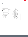
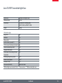
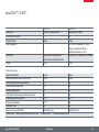
Leica Z6 APO
Leica Z16 APO
User Manual
General Instructions
Safety Concept
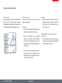
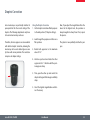
Before using your macroscope for the first time,
please read the "Safety Concept" brochure
included with your instrument. It contains additional information about handling and care.
Use in clean rooms
The Leica Z series can be used in clean rooms
without any problems.
Cleaning
★★ Do not use any unsuitable cleaning agents,
chemicals or techniques for cleaning.
★★ Never use chemicals to clean colored
surfaces or accessories with rubberized
parts. This could damage the surfaces, and
specimens could be contaminated by abraded particles.
Servicing
★★ Repairs may only be carried out by Leica
Microsystems-trained service technicians.
Only original Leica Microsystems spare
parts may be used.
Responsibilities of person in charge of
instrument
★★ Ensure that the Leica macroscope is operated, maintained and repaired by authorized
and trained personnel only.
★★ In most cases, we can provide special solutions on request. Some products can be
modified, and we can offer other accessories for use in clean rooms.
Leica Z6 APO / Z16 APO
User Manual
2
Important Safety Notes
User Manual
The individual modules of the Leica Z series
include an interactive CD-ROM with all relevant
user manuals in other languages. Keep it in a
safe place, and readily accessible to the user.
User manuals and updates are also available for
you to download and print from our web site
www.leica-microsystems.com.
This User Manual describes the special functions of the individual modules of the Leica
Z series and contains important instructions
for their operational safety, maintenance, and
accessories.
You can combine individual system articles
with articles from external suppliers (e.g. cold
light sources, etc.). Please read the user manual
and the safety requirements of the supplier.
Before installing, operating or using the instruments, it is mandatory to read the user manuals
listed above. In particular, please observe all
safety instructions.
To maintain the unit in its original condition
and to ensure safe operation, the user must
follow the instructions and warnings contained
in these user manuals.
The "Safety Concept" booklet contains additional safety information regarding the service
work, requirements and the handling of the
macroscope, accessories and electrical accessories as well as general safety instructions.
Leica Z6 APO / Z16 APO
User Manual
3
Symbols Used
Warning of a danger
This symbol indicates especially important information that must be read and
complied with.
• Failure to comply can cause the following:
★★ Hazards to personnel
★★ Functional disturbances or damaged instruments
Danger due to hot surface
This symbol warns against touching
accessible hot surfaces, e.g. those of
light bulbs.
Important information
This symbol indicates additional information or explanations that intend to
provide clarity.
Warning of hazardous electrical voltage
This symbol indicates especially important information that is mandatory to
read and observe.
Explanatory notes
★★ This symbol within the text stands for additional information and explanations.
Failure to comply can cause the following:
★★ Hazards to personnel
★★ Functional disturbances or damaged instruments
Figures
(1) Numbers in parentheses within the
descriptions relate to the figures and the
items within those figures.
Leica Z6 APO / Z16 APO
User Manual
4
Safety Instructions
Description
★★ The individual modules fulfill the highest
requirements for observation and documentation with the Leica Z series.
Intended use
★★ Refer to "Safety Concept" booklet.
Non-intended use
★★ Refer to "Safety Concept" booklet.
Place of use
★★ Refer to "Safety Concept" booklet.
Never use Z series macroscopes or their components for surgical procedures (for example, on
the eye) unless they are specifically intended
for that purpose.
★★ Electrical components must be placed at
least 10 cm away from the wall and from
flammable substances.
The instruments and accessories described in
this operating manual have been tested for
safety and potential hazards. The responsible
Leica affiliate must be consulted whenever
the instrument is altered, modified or used in
conjunction with non-Leica components that
are outside of the scope of this manual.
★★ Avoid large temperature fluctuations, direct
sunlight and vibrations. These conditions
can distort measurements and micrographic images.
★★ In warm and warm-damp climatic zones,
the individual components require special
care in order to prevent the build-up of
fungus.
Unauthorized alterations to the instrument or
noncompliant use shall void all rights to any
warranty claims.
Leica Z6 APO / Z16 APO
User Manual
5
Safety Instructions (cont'd.)
Responsibilities of person in charge of
instrument
★★ Refer to "Safety Concept" booklet.
Ensure that:
★★ The Z series macroscopes and accessories
are operated, maintained and repaired by
authorized and trained personnel only.
★★ All operators have read, understood and
observe this User Manual, and particularly
the safety regulations.
Repairs, service work
★★ Refer to "Safety Concept" booklet.
★★ Only original Leica Microsystems spare
parts may be used.
★★ Before opening the instruments, switch off
the power and unplug the power cable.
Transport
★★ Use the original packaging for shipping or
transporting the individual modules and
the accessory components.
★★ In order to prevent damage from vibrations, all moving parts that (according to
the user manual) can be assembled and
disassembled by the customer should be
disassembled and packed separately.
Integration in third-party products
★★ Refer to "Safety Concept" booklet.
Disposal
★★ Refer to "Safety Concept" booklet.
Legal requirements
★★ Refer to "Safety Concept" booklet.
Health risks
Workplaces equipped with macroscopes facilitate and improve the viewing task, but they
also impose high demands on the eyes and
holding muscles of the user. Depending on the
duration of uninterrupted work, asthenopia
and musculoskeletal problems may occur. For
this reason, appropriate measures for reduction
of the workload must be taken: Optimal arrangement of workplace, work assignments and
work flow (changing tasks frequently).
★★ Thorough training of the personnel, giving
consideration to ergonomic and organizational aspects.
The ergonomic design and construction of the
Leica Z series are intended to reduce the exertion of the user to a minimum.
Direct contact with eyepieces can be a potential transmission path for bacterial and viral
★★ Touching the live circuit can cause injury.
Leica Z6 APO / Z16 APO
EC Declaration of Conformity
★★ Refer to "Safety Concept" booklet.
User Manual
6
Safety Instructions (cont'd.)
infections of the eye. The risk can be kept to a
minimum by using personal eyepieces for each
individual or detachable eyecups.
Warning
UV radiation could damage the eyes. Therefore:
★★ Never look into the light spot on the specimen plane without a UV protection screen.
Light sources: Safety Instructions
Protective measures of the manufacturer:
★★ UV protection screen in front of the specimen plane prevents the user from looking
directly into the UV rays.
★★ Never look into the eyepieces if no excitation filter is in the beam path.
★★ Dummy filter carriers in the free positions
of the rapid filter changer prevent direct UV
radiation from reaching the eyes.
★★ Do not select a white, strongly reflective
background for the specimen.
★★ Fill empty filter positions with dummy filter
carriers.
Supply unit
Always unplug the supply unit from the power
supply:
★★ When installing and disassembling the
lamp housing
★★ Before opening the lamp housing
★★ When replacing the high-pressure mercury
lamp and other parts, such as the heatabsorbing filter or the collector
★★ During maintenance work on the supply unit
★★ UV filters are installed in the observation
beam paths to protect the eyes.
★★ The stray-light protection on the lamp
housing prevents irradiation of the hands.
Leica Z6 APO / Z16 APO
User Manual
7
Safety Instructions (cont'd.)
Lamp housing
★★ Never open the lamp housing while the
lamp is switched on. Risk of explosion, UV
exposure, blinding!
★★ Before opening the lamp housing, allow it
to cool off for at least 15 minutes. Danger
of explosion!
★★ Never cover the air duct on the lamp
housing. Danger of fire!
Mercury lamp
★★ Follow the user manual and safety instructions provided by the lamp manufacturer, and, in particular, the section on how
to proceed if a lamp breaks and releases
mercury.
★★ For transport, remove the mercury lamp,
transport it in its original packaging and
protect moving parts in the lamp housing
using the transport anchors.
★★ When it has reached the end of its rated life
(follow the manufacturer's specifications
and the minute meter on the supply unit).
★★ To minimize the risk of explosion, replace a
discolored mercury lamp promptly
★★ Leica Microsystems assumes no liability
for damage caused by exploding, incorrectly installed or improperly used mercury
lamps.
Leica Z6 APO / Z16 APO
User Manual
8
Table of Contents
The Leica Z Series
Congratulations!
The Modular Design: Everything is Relative
The Automatic Control System
On We Go
13
14
15
16
Assembly
Incident-light Bases and Manual Focusing Column
Transmitted-light Bases and Manual Focusing Column
Microscope Carrier
Video/Phototube A
Video/Phototube AS ("Slim")
Video/Phototube Y
Coaxial Illuminator (Optional)
Optics Carrier
Fine Focus (Optional)
Objective
Ergo binocular tube
Eyepieces
Objective Slide: Assembly
Objective Slide: Parcentric Adjustment of the Objectives
Transmitted-light Base TL ST
Transmitted-light Base TL BFDF: Before First Use
Transmitted-light Base TL BFDF
18
19
20
21
22
23
24
25
26
27
28
29
30
32
33
34
35
Leica Z6 APO / Z16 APO
TL RC™ / TL RCI™
IsoPro™ Manual Mechanical Stage: Assembly
Leica IsoPro™ Motorized Mechanical Stage: Assembly
Cables: Connections
Cables: Cable Duct
Leica LED3000 NVI™ (Near Vertical Illumination)
36
37
40
44
45
46
Quick Start Guide
Overview of a Manual Leica Z Series Macroscope (Leica Z16 APO)
48
Eyepieces and Focusing
Magnification Factors of the Eyepieces
Using the Eyepieces
The Correct Interpupillary Distance
Dioptric Correction
Reticules
Health Notes
Focusing
Adjusting the Resistance of the Focus Drive
Fine Focusing
Changing Magnification (Zoom)
Enabling and disabling ratchet steps
Iris Diaphragm
50
51
52
53
54
55
56
57
58
59
60
61
User Manual
9
Photography & Video
Photography & Video
Photo Tubes and C-mounts
Trinocular Video/Phototube 50%
Trinocular Video/Phototube 100%
Objectives
Optical Accessories
The Different Types of Objectives
Bases
Leica TL ST Transmitted-light Base: Controls
Leica TL ST Transmitted-light Base: Operation
Leica TL ST Transmitted-light Base: Changing Bulbs
Leica TL BFDF Transmitted-light Base: Controls
Leica TL BFDF Transmitted-light Base: Operation
Leica TL RC™ / TL RCI™: Controls
Leica TL RCI™: The Deflection Mirror
Leica TL RCI™: Color Intensity and Temperature
Leica TL RC™ / TL RCI™: Operation
Leica TL RCI™: Methods in Transmitted Light
Leica TL RCI™: Relief Images
Using Filters
Leica IsoPro™ (Non-motorized): Controls
Leica IsoPro™ (Motorized): Controls
Leica Z6 APO / Z16 APO
63
64
65
66
and
System Illumination
Leica LED3000 NVI™ (Near Vertical Illumination)
86
Accessories
Leica PSC Controller
Leica SmartTouch
Manual Control
Footswitch
88
89
90
91
68
70
71
72
73
74
75
76
77
78
79
80
82
83
84
Dimensional Drawings
Leica Z6 APO
Leica Z16 APO
Objectives
Video/phototube AS
Y tube
Video/Phototube A
Microscope carrier
Focusing arm for probers
Focusing arms
Adapters
Coaxial incident-light housing
User Manual
93
94
95
96
97
98
99
100
101
102
103
10
Specifications
Optical Data – Visual with Y Tube 1.25×
Leica Z6 APO & Z16 APO
Optical Accessories for Leica Z6 APO & Z16 APO
Ambient Conditions and Weights
Leica TL ST Transmitted-light Base
Leica TL BFDF Transmitted-light Base
Leica TL RC™ / TL RCI™
Leica IsoPro™ Motorized XY Stage
105
108
109
110
111
112
113
114
Appendix
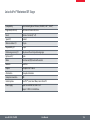
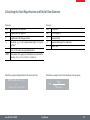
Calculating the Total Magnification and Field of View Diameter
Care, Maintenance, Contact Persons
116
117
Leica Z6 APO / Z16 APO
User Manual
11
The Leica Z Series
Leica Z6 APO / Z16 APO
User Manual
12
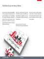
Congratulations!
Congratulations on obtaining your new Leica Z series macroscope. We are
convinced it will exceed your expectations, as the Z series embodies all
the qualities you associate with the name Leica Microsystems: excellent
objectives, high-quality engineering, and reliability. Furthermore, the
modular design ensures that the Z series adapts perfectly to your needs—
no matter which accessories you require for your tasks.
Thanks to the parallax error free observation, measurements are more
accurate and adaptation tasks are easier. Together with a Leica digital
camera, you obtain the maximum amount of high-quality data, which
also makes later evaluations on the computer much easier.
Leica Z6 APO / Z16 APO
Though the reliability and robustness of Leica macroscopes is legendary,
like any high-tech product, the Leica Z series requires a certain degree of
care and attention. Therefore, we recommend that you read this manual.
It contains all the information you need regarding operation, safety and
maintenance. Simply observing a few guidelines will ensure that even
after years of intensive use, your Leica macroscope will continue to work
as smoothly and reliably as on the very first day.
We wish you the best of success in your work— after all, you are now
equipped with the best tool!
User Manual
13
The Modular Design: Everything is Relative
The Leica Z series provides maximum flexibility
in choosing equipment, thanks primarily to the
modular configuration and the compatibility
that Leica has painstakingly maintained for
decades. The optics carriers, eyepieces, bases
and more can be combined in any way you
choose, allowing you to create the macroscope
that best suits your needs.
Leica Z6 APO / Z16 APO
Despite this, you will notice that the controls
and individual components do not differ significantly. Whichever configuration you choose,
you will quickly feel right at home with your
new macroscope.
tation when it comes to devising customerspecific solutions. If you have a special request
that cannot be met with standard parts, contact
your Leica consultant. He or she has a solution
for every problem.
Have a special request? Let us know!
Leica Microsystems enjoys an exceptional repu-
User Manual
14
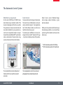
The Automatic Control System
Reliability for your experiments
For the Leica Z6 APO A and Z16 APO A automated macroscopes, motorized control of the
zoom, iris diaphragm and fine focus is possible.
This guarantees not only convenient work, but
also added reliability for your experiments, as
results can be reproduced exactly. In conjunction with the Leica LED3000 NVI™ system illuminators, a wide variety of scenarios can be set up,
saved and restored at the touch of a button.
Control à la carte
You alone determine the degree of automation.
The zoom, focus and illumination can be optionally controlled using the "Leica Application
Suite" (LAS) software solution or via the Leica
SmartTouch touchscreen panel.
To automate your workflows even more, also
integrate the Leica IsoPro™ motorized XY stage
– it positions multiple specimens fully automa-
tically* or turns a series of individual images
into one large, seamless illustration**, to give
only two examples.
Talk to your Leica partner about the wide range
of automation possibilities – he or she will show
you how to get the maximum out of your Leica
macroscope.
* With LAS auxiliary module LAS MultiStep
** With LAS auxiliary module LAS PowerMosaic
The Leica SmartTouch controls all motorized
functions of the Z series and the connected
accessories.
Leica Z6 APO / Z16 APO
The Leica Application Suite (LAS) controls and
photographs fully automatically as desired.
User Manual
15
On We Go
If your new Leica macroscope has already been
assembled and commissioned by your Leica
consultant, click here to skip through the installation instructions and go directly to the Quick
Start Guide on page 47.
Leica Z6 APO / Z16 APO
If, on the other hand, you are assembling the
Leica macroscope yourself, continue with the
"Assembly" chapter, which begins on Page 17.
User Manual
16
Assembly
Leica Z6 APO / Z16 APO
User Manual
17
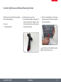
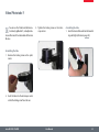
Incident-light Bases and Manual Focusing Column
The first step is to connect the focusing column
to the corresponding base.
Tools used
★★ Allen key provided
Assembling the focusing column
1. Lay the focusing column on the edge of a
table or another stable substrate so that
the three threads at the end of the column
protrude over the edge.
2. Hold the incident-light to the focusing
column and secure it to the base using the
three screws provided.
if someone helps you do so.
Tip: The base can be installed more easily
Leica Z6 APO / Z16 APO
User Manual
18
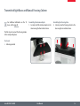
Transmitted-light Bases and Manual Focusing Column
bases, refer to page 33.
For additional information on the TL
Assembling the column adapter
1. Securely install the column adapter on the
column using the four included screws.
Assembling the focusing drive
2. Securely screw the focusing column to the
base using the six included screws.
The first step is to connect the focusing column
to the corresponding base.
Tools used
★★ Allen key provided
Leica Z6 APO / Z16 APO
User Manual
19
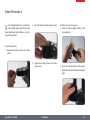
Microscope Carrier
Tools used
★★ Allen key provided
Assembling the Microscope Carrier
1. Press the microscope carrier against the
focusing column.
Leica Z6 APO / Z16 APO
User Manual
2. Tighten the screw using the Allen key provided.
20
Video/Phototube A
Leica digital camera with the Leica LAS
The video/phototube A is used if only a
2. Insert the tube into the microscope carrier.
(Leica Application Suite) software is used to
observe the specimen.
Installing the objective/camera
1. Screw the desired digital camera to the
video objective.
Assembling the tube
1. Unscrew the locking screw on the optics
carrier.
3. Tighten the locking screw on the microscope carrier.
Leica Z6 APO / Z16 APO
User Manual
2. Insert the video objective into the video/
phototube A and turn the knurled ring until
tight.
21
Video/Phototube AS ("Slim")
OEM applications and is usually not used
The video/phototube AS is intended for
on Leica focusing columns.
the rest of the components are installed
After installation on the OEM equipment,
as described on the following pages.
Leica Z6 APO / Z16 APO
User Manual
22
Video/Phototube Y
lar tubes, ErgoModules®, video/phototuYou can use the Y-tube to attach binocu-
3. Tighten the locking screw on the microscope carrier.
bes and the Leica IC A video module of the Leica
M series.
Assembling the tube
1. Insert the desired tube and turn the knurled
ring until tight (refer also to page 28).
Assembling the tube
1. Unscrew the locking screw on the optics
carrier.
2. Insert the tube into the microscope carrier
so that the locking screw faces the rear.
Leica Z6 APO / Z16 APO
User Manual
23
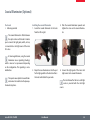
Coaxial Illuminator (Optional)
Tools used
★★ Allen key provided
Installing the coaxial illuminator
1. Guide the coaxial illuminator to the tube
from the left or right.
3. Push the coaxial illuminator upwards and
tighten the screw on the coaxial illuminator.
2. Adjust the coax illuminator so that the port
for the light guide faces the direction that is
the most comfortable for your work.
4. Connect the light guide of the Leica cold
light source to the coaxial illuminator.
the optics carrier and the tube. It enables
The coaxial illuminator is fitted between
you to connect the light guide, which, in turn,
is connected to a cold light source of the Leica
CLS series.
illuminator causes vignetting (shading),
At low magnifications, using the coaxial
which is more or less pronounced depending
on the configuration. This vignetting is not a
malfunction.
nation must be installed on the planapoThe quarter-wave plate for coaxial illumi-
source is provided with the cold light
The User Manual for the Leica cold light
chromatic objectives.
Leica Z6 APO / Z16 APO
source.
User Manual
24
Optics Carrier
Tools used
★★ Allen key provided
1. Unscrew the fastening screw on the optics
carrier.
3. Push the optics carrier upwards and tighten
the fastening screw.
logically if the optional coaxial illumi-
The instructions on this page also apply
nator has been installed (see page 24). In this
case, the optics carrier is attached to the coaxial
illuminator instead of the tube.Assembling the
optics carrier
2. Guide the optics carrier to the tube from
the rear.
Leica Z6 APO / Z16 APO
User Manual
25
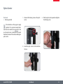
Fine Focus (Optional)
Tools used
★★ Allen key provided
Removing the diaphragm ring
1. Unscrew the 3 fastening screws on the
diaphragm ring of the optics carrier.
Installing the fine focus
1. Place the fine focus on the optics carrier.
2. Remove the diaphragm ring.
2. Tighten the three fastening screws.
and precise focusing in a range of 10 mm.
The optional fine focus allows sensitive
The fine focusing is required for precise focusing at high magnifications.
diaphragm ring must be removed from
Before the fine focus is installed, the
the optics carrier.
Leica Z6 APO / Z16 APO
User Manual
26
Objective
Tools used
★★ None
for coaxial illumination, the analyzer for
You can attach the quarter-wave plate
Attaching the objective
1. Screw the planapochromatic objective to
the diaphragm ring or the optional fine
focus in a counterclockwise direction.
polarization or a ring illuminator to the planapochromatic objectives.
mance
HR and DM objectives are high-perforobjectives and always cause
vignetting. This vignetting is not a malfunction.
Alternative fastening options
★★ If using the objective slide, read the instructions on page 30.
Leica Z6 APO / Z16 APO
User Manual
27
Ergo binocular tube
Tools used
★★ No tools required.
1. Push the tube into the dovetail ring and
rotate it slightly in both directions until the
positioning screw meshes with the guide
groove.
2. While holding the tube only slightly, carefully tighten the positioning screw. It is
automatically brought to the correct position.
Prerequisite for the installation
When using the ergo binocular tube or
another tube, the Y video/phototube
must be used.
Preparations
1. Unscrew the positioning screw and remove
the protective cover.Assembling the tube
Leica Z6 APO / Z16 APO
User Manual
28
Eyepieces
Tools used
★★ None
Magnification range
You can extend the overall magnification
range using available 10×, 16×, 25× and
40× wide-field eyepieces for persons wearing
glasses.
Preparation
1. If you want to use an optional graticule,
insert it now (Page 54).
Inserting the eyepieces
3. Push the eyepieces into the tubes as far as
they will go and check to ensure that they
fit tightly and accurately.
2. Remove the plastic tube guard.
4. Securely tighten the clamping screws.
Leica Z6 APO / Z16 APO
User Manual
29
Objective Slide: Assembly
Supported objectives
2.0× planapochromatic objective
5.0× planapochromatic objective
thread by the movable ring and the 4
You can identify the centerable objective
tion, preferably at an angle of 90°, so that
Orient the objective slide during installa-
the illuminator and the specimen are optimally
accessible. The centerable objective thread is
oriented towards the user.
Installing the objective slide:
1. Unscrew the 3 fastening screws on the
diaphragm ring of the optics carrier.
centering screws on the front side of the ring.
2. Remove the diaphragm ring.
(Continued on next page)
Leica Z6 APO / Z16 APO
User Manual
30
Objective Slide: Assembly (cont'd.)
3. Place the objective slide on the optics
carrier and tighten the three fastening
screws.
Installing the objectives:
The 2× objective must be installed on the
centerable objective thread.
at a greater distance, since this arrangeThe 5× objective is installed by the user
ment offers greater freedom of movement.
1. Screw the objectives onto the objective
slide.
Leica Z6 APO / Z16 APO
User Manual
31
Objective Slide: Parcentric Adjustment of the Objectives
that they are approximately parcentric.
The optics are preset at the factory so
However, these settings vary depending on the
configuration used. If you need a more accurate
parcentric adjustment, it can be carried out
subsequently manually.
The parfocality cannot be adjusted.
Therefore, we recommend always focusing using the 5× objective and then switching
to 2×.
Optimizing the parcentricity
1. Push the 5× planapochromat into the beam
path.
2. Position an easily visible part of a specimen
in the center.
3. Push the 2× planapochromat into the beam
path.
4. Unscrew all 4 centering screws.
5. Look through the eyepieces and tighten
the first centering screw until the objective is moved in the right direction and the
readily visible part of the specimen moves
towards the center.
6. Now tighten the opposite centering screw
slightly.
7. Repeat the process with the other screws
until you obtain parcentricity.
• fore, it is mandatory to unscrew the
No preloaded screws are used. There-
opposite centering screw before tightening the
counter-screw. Otherwise, the objective could
be damaged.
Leica Z6 APO / Z16 APO
User Manual
32
Transmitted-light Base TL ST
Unpacking the base
The base is delivered with the adapter plate
installed. Make sure the instruments are unpacked on a flat, sufficiently dimensioned, and
non-slip surface.
Leica Z6 APO / Z16 APO
Focusing drive and column
1. Unscrew the extension plate from the base
using the Allen key provided.
2. Attach your focusing drive column from
below using the four hexagon-head screws.
3. Re-attach the adapter plate to its original position using the six hexagon-head
screws.
User Manual
33
Transmitted-light Base TL BFDF: Before First Use
Removing the transport anchors
Before you can use the transmittedlight base for the first time, it is absolutely necessary to remove the two transport
anchors.
• Anchor of mirror
Anchor of switching slide
Leica Z6 APO / Z16 APO
User Manual
34
Transmitted-light Base TL BFDF
Standard delivery
The base is delivered with the adapter plate
installed. The selected stage (Leica IsoPro™
mechanical stage or Leica standard stage 10
447 269), and the focusing drive will have to be
mounted later.
Stage assembly
The Leica TL BFDF transmitted-light base can be
equipped with three different stages.
The selected stage is mounted on the base
before commissioning. You can switch between
the stages at any time with just a few hand
movements.
The following paragraph assumes use of the
base without the stage mounted. Disassembly
is performed in reverse order of the following
steps.
Standard stage
1. Take the glass plate from the rectangular
gap in the standard stage.
2. Position the stage on the transmitted-light
base in such way that the four holes align
over those in the base.
3. Attach the stage to the base with the four
supplied hexagon-head screws.
4. Insert the glass plate back into the standard
stage.
★★ Leica IsoPro™ manual mechanical stage
★★ Leica IsoPro™ automatic mechanical stage
★★ Leica standard stage 10 447 269
Leica Z6 APO / Z16 APO
User Manual
35
TL RC™ / TL RCI™
The base is delivered with the adapter plate
installed. The selected stage (Leica IsoPro™
mechanical stage or Leica standard stage 10
447 269), and the focusing drive will have to be
mounted later.
Ensure that the instruments are unpacked on a
level, adequately sized, and nonskid underlay.
Stage assembly
The Leica TL RC™/ RCI™ transmitted-light base
can be equipped with three different Leica
stages. The selected stage is mounted on the
base before commissioning. You can switch
between the stages at any time with just a few
hand movements.
Standard stage
1. Take the glass plate from the rectangular
gap in the standard stage.
2. Position the stage on the transmitted-light
base in such way that the four holes align
over those in the base.
3. Attach the stage to the base with the four
supplied hexagon-head screws.
4. Insert the glass plate back into the standard
stage.
The following paragraph assumes use of the
base without the stage mounted. Disassembly
is performed in reverse order of the following
steps.
Leica Z6 APO / Z16 APO
User Manual
36
IsoPro™ Manual Mechanical Stage: Assembly
Leica IsoPro™ Mechanical Stage
Before the Leica IsoPro™ mechanical stage is
mounted to the base, the axis containing the
control buttons is attached either on the left or
the right side of the mechanical stage.
Before the Leica IsoPro™ mechanical stage is
mounted to the base, the axis containing the
control buttons is attached either on the left or
the right side of the mechanical stage.
Left or right operation
If the controls are to be mounted on the lefthand side, the gear rod on the bottom side of
the mechanical stage must be unscrewed and
reattached in reverse.
If the controls are to be mounted on the lefthand side, the gear rod on the bottom side of
the mechanical stage must be unscrewed and
reattached in reverse.
1. Take the glass plate from the mechanical
stage.
2. Turn the mechanical stage around and
place it onto a non-slip surface.
3. Change the gear rod from the left to the
right-hand side.
4. Skip the next two steps to install the controls.
Leica Z6 APO / Z16 APO
User Manual
37
Leica IsoPro™ Manual Mechanical Stage: Assembly (cont'd.)
1. Take the glass plate from the mechanical
stage and turn it around.
2. Change the gear rod from the left to the
right-hand side.
Control assembly
1. Take the glass plate from the mechanical
stage and turn it around.
2. Attach the axis with the control buttons to
the desired side. The fastener snaps into the
mechanical stage magnetically.
3. Attach the axis with the two supplied hexagon-head screws.
4. Attach the cover rail to the mechanical
stage.
Mechanical stage assembly
1. Place the mechanical stage onto the base.
2. Pull the upper part of the mechanical stage
carefully towards the user, fixing the lower
part onto the transmitted-light base.
3. Attach the mechanical stage evenly to the
three threaded holes.
4. Now move the mechanical stage as far as it
will go in the direction of the column.
5. Insert the glass plate into the mechanical
stage.
Leica Z6 APO / Z16 APO
User Manual
38
Leica IsoPro™ Manual Mechanical Stage: Assembly (cont'd.)
Focusing drive and column
1. Unscrew the extension plate from the base
using the Allen key provided.
2. Attach your focusing drive column from
below using the three hexagon-head
screws.
3. Re-attach the adapter plate to its original
position using the three hexagon-head
screws.
Leica Z6 APO / Z16 APO
User Manual
39
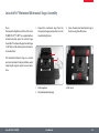
Leica IsoPro™ Motorized Mechanical Stage: Assembly
Basics
The transmitted-light bases of the Leica TL series
(TL BFDF, TL RC™, TL RCI™) are supplied with an
installed extension plate. The selected stage
(Leica IsoPro™ mechanical stage or standard stage
10 447 269) and the focusing drive will have to
be mounted later.
1. Unpack the mechanical stage from the
transport packaging and position it on the
transmitted-light base.
1
The motorized mechanical stage is a sensitive
precision instrument. During installation, avoid
subjecting the stage to impact or severe vibrations.
2
1 Microscope base
2 Motorized mechanical stage
Leica Z6 APO / Z16 APO
2. Secure the motorized mechanical stage to
the base using three M4 screws.
User Manual
3× M4 screws
40
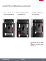
Leica IsoPro™ Motorized Mechanical Stage: Assembly (cont'd.)
3. Remove the two M3 screws and
the holder from the mechanical stage.
4. Remove the two M4 screws and the sleeve
from the mechanical stage.
5. Remove the four shock-absorbing cartons
from the mechanical stage.
anchors in the plastic bag provided
After removal, keep all the transport
for future transport.
Leica Z6 APO / Z16 APO
User Manual
41
Leica IsoPro™ Motorized Mechanical Stage: Assembly (cont'd.)
The bases
The TL BFDF, TL RC™ and RCI™ transmitted-light
bases can be equipped with three different
stages: Standard stage, manual and automated
IsoPro™ mechanical stage. The selected stage is
mounted on the base before commissioning.
You can switch between the stages at any time
with just a few hand movements.
The following paragraph assumes use of the
base without the stage mounted. Disassembly
is performed in reverse order of the following
steps.
Mechanical stage and base
Never move the sledge of the motorized mechanical stage manually in
the X direction, as otherwise the mechanical
system will be damaged!
• 1. Place the mechanical stage onto the base.
2. Pull the upper part of the mechanical stage
carefully towards the user and fasten the
lower part onto the transmitted-light base.
3. Attach the mechanical stage evenly to the
three threaded holes.
4. Now move the mechanical stage as far as it
will go in the direction of the column.
5. Insert the glass plate into the mechanical
stage.
Leica Z6 APO / Z16 APO
User Manual
42
Leica IsoPro™ Motorized Mechanical Stage: Assembly (cont'd.)
Mechanical stage for X-Y stage control
module
1. Plug the CTL2 plug of the mechanical stage
motor into one of the three available CTL2
interfaces.
As soon as all instruments have been plugged
into the control box and it has been plugged
into the power supply, the mechanical stage
initializes and automatically drives to the mid
position.
2. Plug the CTL2 plug of the Leica PSC controller into another CTL2 interface.
4. Connect the PC (where applicable) and X/Y
Stage DCI Module (using a suitable USB
cable).
★★ The third CTL2 interface is available for
connecting other instruments, such as the
Leica foot switch (10 447 398) or TL RCI™
transmitted-light base (10 446 352).
★★ The 15-pin Sub-D interface is intended for
use with the Leica SmartMove™ controller
(11 501 197).
3. Plug a power cable into the socket provided
and into a grounded power socket.
Leica Z6 APO / Z16 APO
User Manual
43
Cables: Connections
The A version of the Leica Z series features
extensive automation options with which various microscope data and settings can be read
out, transferred to the PC and reproduced later.
The terminals
The connection to the PC and to other instruments is made using the terminals on the rear
side of the column:
1
3
2
1. 2× CTL2 terminals for auxiliary equipment
such as the distribution box of the Z series,
the SmartTouch panel, the Leica TL RCI
base and other accessories from the Leica
product range.
2. Terminal for the power supply provided.
3. USB terminal for the connection to the PC.
Leica Z6 APO / Z16 APO
User Manual
44
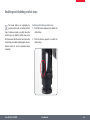
Cables: Cable Duct
The integrated cable duct in the column enables a neat cable layout around the macroscope.
For example, the USB or FireWire cables of the
camera can be stowed in the cable duct.
Leica Z6 APO / Z16 APO
Feeding the cables
1. Unscrew the three screws on the cable
duct.
3. Place the cables in the cable duct and screw
the cover on tightly.
2. Remove the cover of the cable duct.
Tip: Estimate the length of the cable ends you
will need before screwing on the cover. For
thick cables, it is difficult to change the length
retroactively.
User Manual
45
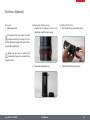
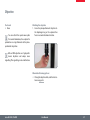
Leica LED3000 NVI™ (Near Vertical Illumination)
Required tools
★★ None
with any objectives that have an outer
The Leica LED 3000 NVI™ can be used
Installing the Leica LED3000 NVI™
1. Connect the Leica LED3000 NVI™ to the
focusing column via the CTL2 connection if
the focusing column is equipped with integrated electronics.
diameter of 58 mm.
Alternative installation for manual columns
1. Connect the external power supply unit (10
450 266) to the Leica LED3000 NVI™.
2. Place the Leica LED3000 NVI™ on the objective from below and tighten the locking
screw.
between 50 mm and 150 mm.
The supported working distance is
Leica Z6 APO / Z16 APO
User Manual
46
Quick Start Guide
Leica Z6 APO / Z16 APO
User Manual
47
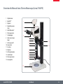
Overview of a Manual Leica Z Series Macroscope (Leica Z16 APO)
1
2
3
4
Digital camera
ErgoTube™
Eyepieces
Adjustable eyepiece
tubes
5 Video/Phototube Y
6 Microscope carrier
7 Iris diaphragm
8 Optics carrier (zoom
body)
9 Click stops on/off
10 Zoom wheel
11 Fine focus
12 Objective
13 LED ring illuminator
14 incident-light
15 Microscope column
16 Focusing drive
1
2
3
4
5
6
7
8
15
16
9
10
11
12
13
14
Leica Z6 APO / Z16 APO
User Manual
48
Eyepieces and Focusing
Leica Z6 APO / Z16 APO
User Manual
49
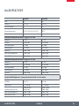
Magnification Factors of the Eyepieces
An eyepiece not only makes it possible to look passively into the macroscope, but also has a critical effect on the maximum magnification. The
magnification factor is between 10x and 40x.
The following eyepieces are available for the Z series:
Magnification
Dioptric Correction
Order number
10×
± 5 diopter settings
10 450 023
16×
± 5 diopter settings
10 450 024
25×
± 5 diopter settings
10 450 025
40×
± 5 diopter settings
10 450 026
Leica Z6 APO / Z16 APO
User Manual
50
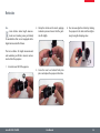
Using the Eyepieces
The eyepieces form the connection between
the tube and the eye of the observer. Simply
push them into the tube and they are ready to
use.
If you do not wear glasses:
1. Hold the eyepiece firmly and rotate the
eyecups forwards counterclockwise.
If you wear glasses:
1. Hold the eyepiece firmly and rotate the
eyecups clockwise towards the rear, as
otherwise the viewing distance is too
great.
2. If an eyepiece is equipped with the integrated dioptric correction, turn the value to
the "0" mark.
2. If an eyepiece is equipped with the integrated dioptric correction, turn the value to
the "0" mark.
Each eyepiece offers a certain magnification
factor that has a determinative effect on the
total magnification. Furthermore, all Leica
eyepieces can be equipped with practical graticules that enable measuring and quantifying of
specimens.
Dioptric Correction
A built-in dioptric correction is available for
eyeglass wearers. For more information, refer
to page 53.
By the way, one benefit of viewing with eyeglasses is a drastically lower risk of bacterial transmission (see page 55). The soft material of the
eyecup also ensures that your glasses will not
be scratched, even if they contact the eyepiece.
Leica Z6 APO / Z16 APO
User Manual
51
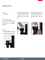
The Correct Interpupillary Distance
The interpupillary distance is correctly set if you
see a single circular image field when looking
at a specimen.
If you are still a novice macroscope user, you
may need a short time to become accustomed
to this. Not to worry—after a little while, it will
become automatic.
Adjusting the interpupillary distance
1. Look into the eyepieces.
2. Hold the eyepieces with both hands. Push
the eyepieces together or separate them
until you see a circular image.
Reference value
The distance between eye and eyepiece measures approx. 22 mm for 10/23B wide-field eyepieces for persons wearing glasses.
Leica Z6 APO / Z16 APO
3. Slowly approach the eyepieces with your
eyes until you can see the complete image
field without corner cutting.
✗
User Manual
✓
52
Dioptric Correction
Leica macroscopes are parfocally matched. A
prerequisite for this the correct setting of the
diopters. The following adjustments only have
to be carried out once by each user.
Therefore, all Leica eyepieces are also available
with built-in dioptric correction, allowing the
macroscope to be used without glasses even
by those with vision problems. The correction
comprises ±5 diopter settings.
Using the Dioptric Correction
1. Set the dioptric correction of both eyepieces
to the mid position ("0" diopter settings).
2. Look through the eyepieces and focus on a
flat specimen.
Now, if you adjust the magnification from the
lowest to the highest level, the specimen is
always brought into sharp focus. If not, repeat
the process.
The system is now parfocally matched to your
eyes.
3. Rotate both eyepieces to the maximum
value of "+5".
4. Hold one eye closed and rotate the other
eyepiece in the "-" direction until the specimen appears sharp.
5. Then, open the other eye and correct the
diopter settings until the image is uniformly
sharp.
6. Select the highest magnification and refocus if necessary.
Leica Z6 APO / Z16 APO
User Manual
53
Reticules
Use
Leica reticules make length measurements and counting easier, particularly
for workstations that are not equipped with a
digital camera and LAS software.
2. Clamp the reticule on the insert, applying
moderate pressure. Ensure that the graticule fits tightly.
4. You can now align the reticule by rotating
the eyepiece in the tube and then tightening it using the clamping screw.
The Leica reticules for length measurements
and numbering are fitted in mounts and are
inserted into the eyepieces.
1. Screw the insert off of the eyepiece.
Leica Z6 APO / Z16 APO
3. Screw the insert and reticule firmly into
place and replace the eyepiece in the tube.
User Manual
54
Health Notes
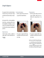
Potential sources of infection
Direct contact with eyepieces is a
potential transmission method for
bacterial and viral infections of the eye. The
risk can be kept to a minimum by using individual eyepieces or detachable eyecups. Eyecups
can be ordered separately. Please contact your
Leica partner.
• Separate eyecups are an effective way of preventing
infections.
Leica Z6 APO / Z16 APO
User Manual
55
Focusing
Focusing raises or lowers the macroscope
using the focusing drive. The specimen detail is
brought into sharp focus as soon as it is in the
focal point of the objective.
★★ The focusing drive can be operated either
left- or right-handed.
Focusing
★★ The inner, coarse adjustment is used for
covering great distances.
Coarse/fine adjustment
The sharpness is adjusted using the coarse/fine
adjustment.
★★ The outer, fine adjustment is used for fine
focusing.
• load of up to 15 kg.
2. The coarse/fine adjustment carries a
ment is 1 µm.
The resolution of the coarse/fine adjust-
Leica Z6 APO / Z16 APO
User Manual
56
Adjusting the Resistance of the Focus Drive
Adjusting the resistance
Is the focus movement too loose or too tight?
Does the outfit tend to slide downwards? The
resistance can be adjusted individually depending on the equipment weight and personal
preferences as follows:
1. Grip the outer drive knobs with both hands
and turn them towards each other until the
desired resistance is reached during focusing.
Leica Z6 APO / Z16 APO
User Manual
57
Fine Focusing
and precise focusing in a range of 10 mm.
The optional fine focus allows sensitive
The fine focusing is required for precise focusing at high magnifications.
Fine Focusing
1. Using the focusing drive, focus on the specimen as accurately as possible (see p. 56).
2. Rotate the fine focus to optimize the focus.
Leica Z6 APO / Z16 APO
User Manual
58
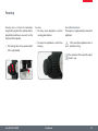
Changing Magnification (Zoom)
The Z series macroscopes have an integrated
zoom. The name indicates the zoom range
covered:
Zooming
1. Look into the eyepieces.
2. Focus on the specimen.
★★ Leica Z6 APO (A) = 6.3:1
★★ Leica Z16 APO (A) = 16:1
3. Rotate the zoom wheel until the desired
magnification is configured.
used either left or right-handed.
The rotary knob for the zoom can be
Leica Z6 APO / Z16 APO
User Manual
59
Enabling and disabling ratchet steps
operated either with or without ratchet
The zoom button can optionally be
steps. Continuous zoom is possible when the
ratchet steps are disabled, which many users
find convenient. On the other hand, when the
ratchet steps are enabled, photographs, measurement results etc. can be reproduced more
accurately.
Leica Z6 APO / Z16 APO
Enabling and disabling ratchet steps
1. Push the button downwards to disable the
ratchet steps.
2. Push the button upwards to enable the
ratchet steps.
User Manual
60
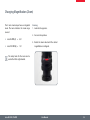
Iris Diaphragm
your Z series macroscope fulfills the same
The iris diaphragm in the optics carrier of
purpose as the iris diaphragm in a camera: it
regulates the available light, which changes
the depth of field. The "depth of field" (or "focus
depth") is the area of a specimen that is brought
into sharp focus.
Leica Z6 APO / Z16 APO
Closing the iris diaphragm
★★ Close the iris diaphragm by turning the
knob to the right in the direction indicated
by "1". The subject appears darker and the
depth of field increases.
User Manual
Opening the Iris Diaphragm
★★ Open the iris diaphragm by turning the
knob to the left in the direction indicated
by "5". The subject now appears brighter,
but the depth of field decreases.
61
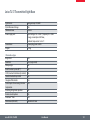
Photography & Video
Leica Z6 APO / Z16 APO
User Manual
62
Photography & Video
For most macroscope users, digital documentation has become an invaluable part of their
work. Research results can be presented in an
attractive manner; measurements on the digital image provide clarity and, in conjunction
with the motorized IsoPro™ mechanical stage,
even images of large specimens can be captured step by step and automatically joined to
create a new complete image.
Leica DFC cameras
However, if you require absolute control over
the camera and need the capability for measurement, evaluation and more in addition to
photography, the digital Leica DFC cameras are
exactly right for you. Together with the Leica
Application Suite, they provide virtually limitless freedom of use. For additional information about Leica cameras, refer to the camera's
documentation.
Leica Application Suite
The "Leica Application Suite", or "LAS" for short,
is, as it were, the digital extension of the Leica
Z series macroscopes. In addition to capturing
images, it lets you control the macroscope, illuminator, stages, cameras and more. For additional information, refer to the LAS online help.
Adapter
If camera control using the Leica Application
Suite is not required, conventional mirror reflex
and rangefinder cameras from third-party
manufacturers can be used. For this purpose,
Leica Microsystems offers a variety of adapters
that can be used together with the 50% and
100% trinocular tubes.
Leica Z6 APO / Z16 APO
User Manual
63
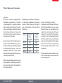
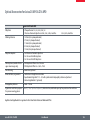
Photo Tubes and C-mounts
Application
All Leica DFC cameras are equipped with a
standardized C-mount interface. In turn, the
C-mount adapter for the respective trinocular
tube is connected to this interface. This adapter
creates a solid mechanical connection between
the macroscope and camera and ensures optimum rendering of the macroscopic image on
the image sensor of the camera.
Usually, the ideal is for the digital camera to
capture as much of the field of vision as possible, while excluding as much of the black edge
of the field of vision as possible. To do so, the
magnification factor of the C-mount adapter
must match the image format of the sensor as
closely as possible (see table).
Alternatively, you can also use a C-mount adapter with higher magnification. This primarily
avoids the critical border area of the field of
vision and concentrates on the center of the
field of vision.
Camera
DFC295
optimal
(large
image field)
suitable
(smaller
image field)
0.5×
0.63×
DFC420
0.5×
0.63×
DFC490
0.63×
0.8×
DFC500
0.63×
0.8×
Cameras from third-party suppliers
In addition to Leica DFC cameras with the standardized C-mount interfaces, you can connect
third-party cameras such as single-lens reflex
cameras to the macroscope using a T2 bayonet
adapter. To do so, instead of the C-mount adapter, simply use the corresponding SLR adapter
with T2 connection. However, these third-party
cameras are not integrated into the Leica Application Suite and have to be operated using
the corresponding software from the camera
manufacturer.
The Leica digital cameras are detailed in a separate user manual along with instructions for
their assembly and use.
If there is unwanted shading at the corners even
with a compatible C-mount adapter installed, it
can be corrected using the "Shading function"
of the camera software.
Leica Z6 APO / Z16 APO
User Manual
64
Trinocular Video/Phototube 50%
Use
With its third beam path, the trinocular video/
phototube 50% enables you to simultaneously
view and photograph a specimen. The available
light is divided as follows:
★★ 50% is available for the two eyepieces.
★★ 50% of the light is diverted to the video/
photo beam path.
Assembly
Fasten the "trinocular tube 50%" to the optics
carrier instead of the ErgoTube™ (refer also to
page 28).
Leica Z6 APO / Z16 APO
User Manual
65
Trinocular Video/Phototube 100%
Use
With its third beam path, the trinocular video/
phototube 100% enables you to either view or
photograph a specimen. This means that 100%
of the light is available to one or the other beam
path. The other beam path remains opaque or
black.
Assembly
Fasten the "trinocular tube 100%" to the optics
carrier instead of the binocular ErgoTube (refer
also to page 28).
Leica Z6 APO / Z16 APO
Switchover
★★ Turn the controller on the right side of the
tube into the horizontal position in order to
guide all available light into the eyepieces.
You can now observe the specimen.
★★ Turn the controller on the right side of the
tube into the vertical position in order to
guide all available light into the camera.
You can now photograph the specimen.
User Manual
66
Objectives and
Optical Accessories
Leica Z6 APO / Z16 APO
User Manual
67
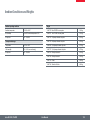
The Different Types of Objectives
To meet the various requirements regarding
imaging properties, there is a choice of highquality interchangeable planachromatic and
planapochromatic objectives and also lowerpriced interchangeable achromatic objectives.
You can use the objectives on the Z6 APO or Z16
APO zoom systems or with the fine focusing.
★★ Also available are the M series 0.63×, 0.5×,
0.32× achromatic objectives, which can be
attached to the zoom or the fine focusing
using an adapter.You can attach the vertical
illuminator or the attachment for incident/
oblique observation to the achromatic
objective.
Achromatic objectives with a long focal
length
For special applications, achromatic objectives
with long working distances and focal lengths
of f=100 mm to 400 mm are available.
★★ We recommend using the 1×, 2×, 5×, 0.8×,
0.5× planapochromatic objectives in order
to take advantage of the high performance
of the apochromatic zoom system.
★★ You can attach the quarter-wave plate for
coaxial illumination, the analyzer for polarization or the ring illuminator to the planapochromatic objectives.
Leica Z6 APO / Z16 APO
User Manual
68
Bases
Leica Z6 APO / Z16 APO
User Manual
69
Leica TL ST Transmitted-light Base: Controls
1
2
1
3
4
Extension plate of the
transmitted-light base TL ST
1 Adapter plate for easy assembly of focusing
drives
2 Removable glass plate
3 Controller for light intensity
4 Adjustment for deflection mirror
Leica Z6 APO / Z16 APO
User Manual
2
3
Rear side of the transmitted-light base TL ST
1 Screws for changing the halogen lamp
2 Power connection socket
3 Power switch
70
Leica TL ST Transmitted-light Base: Operation
Light intensity control
The left control adjusts the intensity of the
12 V/20 W halogen illumination.
1. Switch on the illumination of the base at
the power switch.
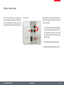
Transmitted-light control
The transmitted-light base TL BFDF has a slider
that automatically moves the deflection mirror
in the base when moved. The mirror is kept in
the correct position at all times and permits
smooth changeover between bright field and
opaque transmitted light.
Bright field
Bright field is suitable for examining translucent objects featuring contrasting structures.
The object is directly illuminated from below
and is seen in its natural colors against a bright
background.
★★ Move the slider backwards until the desired
effect is achieved.
3. Focus on the specimen.
3. Set the illumination to the desired intensity
using the left control.
Inclined transmitted light
Transmitted light that traverses the object obliquely will provide additional resolution and
information when observing semitransparent,
opaque objects.
★★ Slowly pull the slider towards yourself until
the desired effect is achieved.
Leica Z6 APO / Z16 APO
User Manual
71
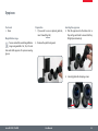
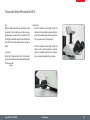
Leica TL ST Transmitted-light Base: Changing Bulbs
Changing the halogen lamp
Before you change the lamp, it is absolutely necessary to unplug the power
plug from the base to prevent the risk of electric shock!
Changing Bulbs
1. Unscrew the two screws on the heat sink
and pull the heat sink out, along with the
lamp.
Precautionary measures
When inserting the lamp, ensure that
the cables are inside the two metal
clamps. This prevents the cables from getting
caught during insertion.
• during operation. Therefore, to avoid
The halogen lamp becomes very hot
being burned, let the base cool off for approx.
10 minutes after switching it off!
• your bare fingers—this drastically redu-
Do not touch new halogen lamps with
ces the service life of the lamp!
2. Carefully pull out the lamp and mount by
pulling them upwards.
3. Disconnect the lamp from the mount.
4. Insert the new lamp into the mount and
reinsert the lamp holder.
Leica Z6 APO / Z16 APO
User Manual
72
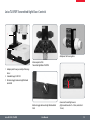
Leica TL BFDF Transmitted-light Base: Controls
1
2
Adapter at the focusing drive
3
Extension plate of the
Transmitted-light Base TL BFDFb
1 Adapter plate for easy assembly of focusing
drives
2 Standard stage 10 447 269
3 Button to toggle between bright field and
dark field
Button to toggle between bright field and dark
field
Leica Z6 APO / Z16 APO
User Manual
Connector for cold light sources
(light conductor active f = 10mm, end tube f =
13mm)
73
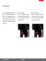
Leica TL BFDF Transmitted-light Base: Operation
Light intensity control
Observe the user manual—in particular, all safety regulations—from the
manufacturers of the light guide and cold light
source.
• ★★ Switch on the cold light source according to
the manufacturer's user manual and adjust
the brightness.
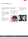
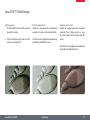
Bright field
Bright field is suitable for examining translucent objects featuring contrasting structures.
The object is directly illuminated from below
and is seen in its natural colors against a bright
background.
★★ Turn the control as far as it will go towards
"BF" ("bright field").
Dark field
In dark-field illumination, a ring illuminator is
used in such a way that the direct light
does not reach the objective without a specimen. Only the structure of semitransparent,
opaque objects disperses the light, making the
object visible against a dark background.
★★ Turn the control as far as it will go towards
"DF" ("dark field").
Transmitted-light control
The Leica TL BFDF transmitted-light base has
a control that switches the light from "bright
field" to "dark field".
Fingertip with bright field illumination
Leica Z6 APO / Z16 APO
User Manual
Identical subject with dark field illumination
74
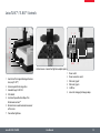
Leica TL RC™ / TL RCI™: Controls
1
2
1
2
3
4
5
6
7
3 45
6
Vertical column - transmitted-light base adapter plate
1
2
3
4
5
6
1 Heat sink of the integrated halogen illumination (only TL RCI™)
2 Extension plate for focusing drives
3 Standard stage 10 447 269
4 Filter holder
5 Control of top and bottom flaps of the
Rottermann Contrast™
6 Button for mirror and horizontal movement
of the mirror
7 Transmitted-light base
Leica Z6 APO / Z16 APO
User Manual
Power switch
Power connection socket
USB socket, type B
USB socket, type A
2 CAN bus
Screws for changing the halogen lamp
75
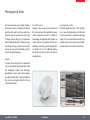
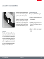
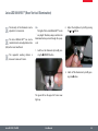
Leica TL RCI™: The Deflection Mirror
The concave cutout on the handle indicates the
concave side of the mirror, allowing intuitive
operation at any time without eye contact.
1
The angle of light incidence in the specimen
plane changes depending on the tilt and position of the mirror. As a result, switching between
transmitted-light bright field, oblique illumination and dark field-like illumination is possible.
★★ Turning the deflection mirror from the flat
to the concave side
★★ Slight tilting to guide the light beam
through the specimen plane at a steeper or
flatter angle
★★ Moving the deflection mirror (forwards/
back)
Tilted mirror
The built-in mirror features one flat and one
concave side and can be rotated and moved.
The concave side has been specially designed
for the optical requirements of objectives with
a high numerical aperture. The black rotary
knob on the left side of the transmitted-light
base can be used to rotate the built-in pathfolding mirror and move it forwards/back.
Leica Z6 APO / Z16 APO
Functions of the rotary knob
The rotary knob (1) fulfills the following tasks:
User Manual
76
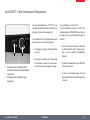
Leica TL RCI™: Color Intensity and Temperature
The transmitted-light base TL RCI™ has two
electronic potentiometers that control the color
intensity (1) and color temperature (2).
The controller for the color temperature simultaneously serves as an electronic shutter:
★★ To interrupt your work, click the potentiometer (2).
1
2
1 Potentiometer for controlling the CCIC™
(Constant Color Intensity Control) illumination intensity
2 Potentiometer for controlling the color
temperature
Leica Z6 APO / Z16 APO
★★ Click again to switch on the illumination.
The electronics returns the color temperature to the previously configured settings.
Using a USB mouse (only TL RCI™)
The Leica USB mouse controls the CCIC™ and
dimming function of the TL RCI™ base. Connect
the mouse to the corresponding USB port of
the base.
★★ The scroll wheel of the mouse is occupied
by default with the CCIC™ control system
and is used to control the illumination
intensity.
★★ To switch the illumination on or off, briefly
click the scroll wheel.
★★ To enter or exit dimming mode, click and
hold down the scroll wheel for longer than
2 seconds.
User Manual
77
Leica TL RC™ / TL RCI™: Operation
Setting the relief contrast
The two switches on the left side of the transmitted-light base TL RC™/TL RCI™ activate two
built-in flaps. The outer switch (1) controls the
inverted relief contrast, and the inner switch (2)
adjusts the positive relief contrast.
1
2
Depending on the flap position, a part of
the opening of the built-in Fresnel lenses are
covered, which results in the different contrast
effects. Phase structures typically act as spatial,
relief-type images—in the positive relief contrast like hills, in the inverted relief contrast like
valleys.
Increased contrast without relief is attained if
both diaphragms are set to 45°. A gap-like illuminated area is created. By tilting the deflection
mirror slightly, you can move the gap over the
entire field of view and quickly toggle between
positive and negative relief images. The dynamic effect makes it easy to distinguish phase
structures from amplitude structures.
(refractive index of the environment) and the
perception of the viewer, it is possible that the
switches described below for positive and inverted relief contrast are to be operated in reverse.
This means that the lower switch, rather than
the upper switch, controls the inverted relief
contrast and vice-versa.
3
1 Switch for adjusting the inverted relief contrast
2 Switch for adjusting the positive relief contrast
3 Deflection mirror
Leica Z6 APO / Z16 APO
User Manual
78
Leica TL RCI™: Methods in Transmitted Light
Vertical bright-field illumination
Suitable for stained amplitude specimens with
sufficient contrast.
The light beams are deflected vertically through
the specimen. This results in an accurate bright
field with maximum brightness.
Leica Z6 APO / Z16 APO
Inclined transmitted light
Suitable for semitransparent, opaque specimens such as foraminifera and fish eggs. Move
the deflection mirror until the desired data are
visible.
User Manual
Single-sided dark field
Suitable for fixed specimens and fine structures.
The flatter the angle at which the light beams
are deflected into the specimen plane, the
darker the substrate appears. A dark field-like
transmitted light is created. Outlines, fine edges
and structures are bright, in contrast with the
dark background, through diffraction of the
light beams on the dark background.
79
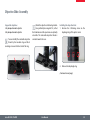
Leica TL RCI™: Relief Images
Starting position
1. Push the deflection mirror all the way back
towards the column.
Positive relief contrast
Suitable for semitransparent and transparent
specimens. The phase structures look like hills.
2. Turn the deflection mirror into the notch
position at an angle of 45°.
The effect can be strengthened or weakened by
gently tilting the deflection mirror.
Negative relief contrast
Suitable for semitransparent and transparent
specimens. These settings result in a negative relief contrast. Phase structures look like
valleys.
The effect can be strengthened or weakened by
gently tilting the deflection mirror.
Leica Z6 APO / Z16 APO
User Manual
80
Leica TL RCI™: Relief Images (cont'd.)
Dynamic relief contrast
Suitable for semitransparent and transparent
specimens.
By tilting the deflection mirror slightly, you can
move the gaps over the entire field of view and
quickly toggle between positive and negative
relief images. The dynamic effect makes it easy
to distinguish phase structures from amplitude
structures.
Leica Z6 APO / Z16 APO
Constraints
The relief methods provide good results from
mid-zoom to high magnifications and with 1×,
1.6× and 2× objectives. In the lower zoom half
and with weaker specimens, the object field
may not be uniformly illuminated.
We recommend using the transmitted-light
base with 1× or higher objectives, and not
objectives with a long focal length.
User Manual
81
Using Filters
Filters for Leica TL RC™ and TL RCI™
The transmitted-light bases TL RC™ and TL RCI™
can be equipped with up to three filters—
available as accessories—simultaneously. By
customer request, the filters are also available
as one-off items.
2. Take the empty filter from an available filter
slot in the filter holder.
Daylight filter for Leica TL ST
A daylight filter is also available for the Leica TL
ST transmitted-light base.
3. Insert the desired filter.
1. Switch off the light source or click (Leica TL
RCI™) the button for the shutter.
4. Switch the light source back on.
Leica Z6 APO / Z16 APO
User Manual
82
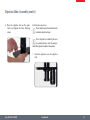
Leica IsoPro™ (Non-motorized): Controls
Operating the Leica IsoPro™ mechanical
stage
1. To move the stage in the X direction, rotate
the outer knob.
2. To move the stage in the Y direction, rotate
the inner control ring.
1
Leica Z6 APO / Z16 APO
2
User Manual
83
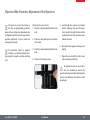
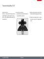
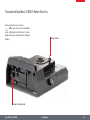
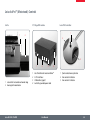
Leica IsoPro™ (Motorized): Controls
IsoPro
X/Y Stage DCI module
1
Leica PSC Controller
1
2
2
3
1
1 Leica IsoPro™ motorized mechanical stage
2 Housing with motorization
Leica Z6 APO / Z16 APO
1
2
3
4
2
3
4
Sub-D interface for Leica SmartMove™
3 CTL2 interfaces
USB interface (type B)
Socket for grounded power cable
User Manual
1 Quick control/memory function
2 Fine control in X direction
3 Fine control in Y direction
84
System Illumination
Leica Z6 APO / Z16 APO
User Manual
85
Leica LED3000 NVI™ (Near Vertical Illumination)
adjusted in 10 increments.
The intensity of the illuminator can be
The Leica LED3000 NVI™ can also be
controlled via the Leica Application Suite
(LAS) or the Leica SmartTouch.
between 50 mm and 150 mm.
The supported working distance is
Use
The light of the Leica LED3000 NVI™ can be
very bright. Therefore, always switch on the
illuminator before you look through the eyepieces!
• 2. Adjust the brightness by briefly pressing
the or buttons.
1. Switch on the illuminator by briefly pressing the (ON/OFF) button.
3. Switch off the illuminator by briefly pressing the button.
The green LED on the upper left corner now
lights up.
Leica Z6 APO / Z16 APO
User Manual
86
Accessories
Leica Z6 APO / Z16 APO
User Manual
87
Leica PSC Controller
Use
The Leica PSC controller gives you precision
control of the Leica IsoPro™ motorized mechanical stage.
Passing over the specimen quickly
★★ Move the joystick in any desired direction (including diagonally) to control the
mechanical stage quickly.
Control by LAS
The instructions for controlling the Leica
IsoPro™ using the Leica Application Suite are
provided in the software's help file.
Connection
Connect the Leica PSC controller and the Leica
IsoPro™ motorized cross-stage to the DCI box.
Fine control of the mechanical stage
The motorized Leica IsoPro™ mechanical stage
offers an accuracy of up to 0.25µm. To move to
a position with maximum accuracy, use the left
and right knobs on the joystick.
Leica Z6 APO / Z16 APO
User Manual
88
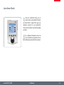
Leica SmartTouch
control and save all automatic functions
The Leica SmartTouch allows you to
and reload them if required. This gives you
maximum assurance for your experiments,
since you can reproduce every situation quickly
and easily.
Leica SmartTouch and operation, refer to
For additional information about the
the User Manual provided with the instrument.
Leica Z6 APO / Z16 APO
User Manual
89
Manual Control
Focusing
Turning counterclockwise = downwards
Turning clockwise = upwards
Toggle between
coarse and fine focusing
1. Press the black button briefly.
Information about the focus positions
★★ Focus positions can be stored using the
manual control or on the computer.
★★ A total of up to 5 focus positions can be
stored.
★★ If a sixth focus position is stored, the one
nearest to it will be deleted.
★★ Each focus position can be canceled individually.
★★ The system will travel to each of the individual focus positions in the sequence in
which they were stored.
When the system is switched on, the
coarse focus is always switched on also.
Leica Z6 APO / Z16 APO
Saving the focus positions
1. Focus on the first specimen detail.
2. Press the red switch for at least 1.5 seconds.
Short beeps provide confirmation.
3. Focus on the next specimen details and
save these positions also.
Moving to stored focus positions
1. Press the red switch briefly.
Deleting stored positions
Press the red switch until you hear the audible
signal: 2 short beeps – pause – 2 long beeps.
★★ Switching off the system cancels all of the
stored focus positions.
User Manual
90
Footswitch
Focusing
Toggling between coarse and fine focus
Press the left and right switches simultaneously.
1
2
the footswitch.
Focus positions cannot be stored using
1 Upwards
2 Downwards
Leica Z6 APO / Z16 APO
User Manual
91
Dimensional Drawings
Leica Z6 APO / Z16 APO
User Manual
92
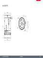
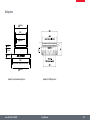
Leica Z6 APO
ße Zoomsysteme, Koaxial-Auflichtgehäuse
Leica Z6 APO
Leica Z16 APO
Leica Z6 APO / Z16 APO
User Manual
93
e
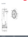
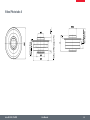
Leica Z16 APO
a Z6 APO
Leica Z16 APO
Leica Z6 APO / Z16 APO
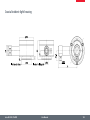
Koaxial-Auflichtgehäuse
User Manual
94
Objectives
Leica Z6 APO / Z16 APO
User Manual
95
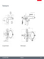
Video/phototube AS
Leica Z6 APO / Z16 APO
User Manual
96
Y tube
Leica Z6 APO / Z16 APO
User Manual
97
Video/Phototube A
Leica Z6 APO / Z16 APO
User Manual
98
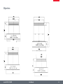
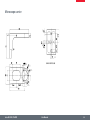
Microscope carrier
Carrier for AS tube
Leica Z6 APO / Z16 APO
User Manual
99
Ø43
25.5
24
4x Ø4.5 holes (M4) for Machine Interface
Ø87
Interface
Ø76
60
117
69
24
54
40
10
Highest Focusing Position
Lowest
Focusing
Position
25
71
37
0.5
Focusing arm for probers
77.5
Leica Z6 APO / Z16 APO
User Manual
100
Focusing arms
69
25
25
25
101
Highest
Focusing
Positio
Lowest
Focusing
Position
Ø87
60
Ø76
25
Interface for Ø25 Column
Focusing arm for bonders
Leica Z6 APO / Z16 APO
Tiltable focusing arm
User Manual
101
Adapters
∅ 45 mm
M42
(Fine Focus Interface)
∅ 40 mm
6 mm
11 mm
8 mm
M60
(Achromat Objective Interface)
∅ 66 mm
Adapter for achromatic objectives
Leica Z6 APO / Z16 APO
Adapter for DM objectives
User Manual
102
Coaxial incident-light housing
Leica Z6 APO / Z16 APO
User Manual
103
Specifications
Leica Z6 APO / Z16 APO
User Manual
104
Optical Data – Visual with Y Tube 1.25×
Objectives
1× planapochromatic
0.5× planapochromatic
0.8× planapochromatic
2× planapochromatic
97 mm
187 mm
112 mm
39 mm
Working distances
Eyepieces
Zoom
position
10×/23B
Leica Z6 APO / Z16 APO
0.57
0.8
1
1.25
1.6
2
2.5
3.2
3.6
4
5
6.3
8
9.2
Total
mag.
Object
field ∅
Total
mag.
Object
field ∅
Total
mag.
Object
field ∅
×
mm
×
mm
×
7.1
10
12.5
15.6
20
25
31.3
40
45
50
62.5
78.8
100
115
32.3
23.0
18.4
14.7
11.5
9.2
7.4
5.8
5.1
4.6
3.7
2.9
2.3
2.0
3.6
5
6.3
7.8
10
12.5
15.6
20
22.5
25
31.3
39.4
50
57.5
64.6
46.0
36.8
29.4
23.0
18.4
14.7
11.5
10.2
9.2
7.4
5.8
4.6
4.0
5.7
8
10
12.5
16
20
25
32
36
40
50
63
80
92
User Manual
5× planapochromatic
20 mm
Total
mag.
Object
field ∅
Total
mag.
Object
field ∅
mm
×
40.4
28.8
23.0
18.4
14.4
11.5
9.2
7.2
6.4
5.8
4.6
3.7
2.9
2.5
14.3
20
25
31.3
40
50
62.5
80
90
100
125
157.5
200
230
mm
×
mm
16.1
11.5
9.2
7.4
5.8
4.6
3.7
2.9
2.6
2.3
1.8
1.5
1.2
1.0
35.6
50
62.5
78.1
100
125
156.3
200
225
250
312.5
393.8
500
575
6.5
4.6
3.7
2.9
2.3
1.8
1.5
1.2
1.0
0.9
0.7
0.6
0.5
0.4
105
Optical Data – Visual with Y Tube 1.25× (cont'd.)
Objectives
1× planapochromatic
Working distances
97 mm
0.8× planapochromatic
187 mm
2× planapochromatic
112 mm
5× planapochromatic
39 mm
20 mm
Total
mag.
Object
field ∅
Total
mag.
Object
field ∅
Total
mag.
Object
field ∅
Total
mag.
Object
field ∅
Total
mag.
Object
field ∅
×
mm
×
mm
×
mm
×
mm
×
mm
16×/15B
0.57
0.8
1
1.25
1.6
2
2.5
3.2
3.6
4
5
6.3
8
9.2
11.4
16
20
25
32
40
50
64
72
80
100
126
160
184
21.1
15.0
12.0
9.6
7.5
6.0
4.8
3.8
3.3
3.0
2.4
1.9
1.5
1.3
5.7
8
10
12.5
16
20
25
32
36
40
50
63
80
92
42.1
30.0
24.0
19.2
15.0
12.0
9.6
7.5
6.7
6.0
4.8
3.8
3.0
2.6
9.1
12.8
16
20
25.6
32
40
51.2
57.6
64
80
100.8
128
147.2
26.3
18.8
15.0
12.0
9.4
7.5
6.0
4.7
4.2
3.8
3.0
2.4
1.9
1.6
22.8
32
40
50
64
80
100
128
144
160
200
252
320
368
10.5
7.5
6.0
4.8
3.8
3.0
2.4
1.9
1.7
1.5
1.2
1.0
0.8
0.7
57
80
100
125
160
200
250
320
360
400
500
630
800
920
4.2
3.0
2.4
1.9
1.5
1.2
1.0
0.8
0.7
0.6
0.5
0.4
0.3
0.3
25×/9.5B
0.57
0.8
1
1.25
1.6
2
2.5
3.2
3.6
4
5
6.3
8
9.2
17.8
25
31.3
39.1
50
62.5
78.1
100
113
125
156
197
250
288
13.3
9.5
7.6
6.1
4.8
3.8
3.0
2.4
2.1
1.9
1.5
1.2
1.0
0.8
8.91
12.5
15.6
19.5
25
31.3
39.1
50
56.3
62.5
78.1
98.4
125
144
26.7
19.0
15.2
12.2
9.5
7.6
6.1
4.8
4.2
3.8
3.4
2.4
1.9
1.6
14.3
20
25
31.3
40
50
62.5
80
90
100
125
158
200
230
16.7
11.9
9.5
7.6
5.9
4.8
3.8
3.0
2.6
2.4
1.9
1.5
1.2
1.0
35.6
50
62.5
78.1
100
125
156
200
225
250
313
394
500
575
6.7
4.8
3.8
3.0
2.4
1.9
1.5
1.2
1.1
1.0
0.8
0.6
0.5
0.4
89
125
156
195
250
313
391
500
562
625
781
984
1250
1438
2.7
1.9
1.5
1.2
1.0
0.8
0.6
0.5
0.4
0.4
0.3
0.2
0.2
0.2
Eyepieces
Zoom
position
0.5× planapochromatic
Leica Z6 APO / Z16 APO
User Manual
106
Optical Data – Visual with Y Tube 1.25× (cont'd.)
Objectives
1× planapochromatic
0.5× planapochromatic
0.8× planapochromatic
2× planapochromatic
97 mm
187 mm
112 mm
39 mm
Working distances
Eyepieces
Zoom
position
40×/6B
Leica Z6 APO / Z16 APO
0.57
0.8
1
1.25
1.6
2
2.5
3.2
3.6
4
5
6.3
8
9.2
5× planapochromatic
20 mm
Total
mag.
Object
field ∅
Total
mag.
Object
field ∅
Total
mag.
Object
field ∅
Total
mag.
Object
field ∅
Total
mag.
Object
field ∅
×
mm
×
mm
×
mm
×
mm
×
mm
14.3
20
25
31.3
40
50
62.5
80
90
100
125
158
200
230
16.8
12.0
9.6
7.7
6.0
4.8
3.8
3.0
2.7
2.4
1.9
1.5
1.2
1.0
22.8
32
40
50
64
80
100
128
144
160
200
252
320
368
10.5
7.5
6.0
4.8
3.8
3.0
2.4
1.9
1.7
1.5
1.2
1.0
0.8
0.7
57
80
100
125
160
200
250
320
360
400
500
630
800
920
28.5
40
50
62.5
80
100
125
160
180
200
250
315
400
460
8.4
6.0
4.8
3.8
3.0
2.4
1.9
1.5
1.3
1.2
1.0
0.8
0.6
0.5
User Manual
4.2
3.0
2.4
1.9
1.5
1.2
1.0
0.8
0.7
0.6
0.5
0.4
0.3
0.3
143
200
250
313
400
500
625
800
900
1000
1250
1575
2000
2300
1.7
1.2
1.0
0.8
0.6
0.5
0.4
0.3
0.3
0.2
0.2
0.2
0.1
0.1
107
Leica Z6 APO & Z16 APO
Zoom
Leica Z6 APO
Leica Z16 APO
6.3:1
16:1
Zoom factor
0.57× – 3.6×
0.57× – 9.2×
Built-in iris diaphragm
✔
✔
Engageable zoom positions
0.57 / 0.8 / 1 / 1.25 / 1.6 / 2 / 2.5 / 3.2 / 3.6
0.57 / 0.8 / 1 / 1.25 / 1.6 / 2 / 2.5 / 3.2 / 4 / 5 / 6.3
/ 8 / 9.2
Zoom speed
–
–
Visual data with 1× planapochromatic objective / 10× eyepieces / 1.25× Y tube
Magnification
7.1× – 45×
7.1× – 115×
Resolution
60 – 351 Lp / mm
51 – 336 Lp / mm
9.8 – 1.49 µm
Visible structural width
8.3 – 1.4 µm
Numerical Aperture
0.02 – 0.117 nA
0.017 – 0.112 nA
Object field ∅
32.3 mm – 5.1 mm
32.3 mm – 2.0 mm
Depth of field (diaphragm open)
3.1 mm – 0.09 mm
3.8 mm – 0.05 mm
Depth of field (dia. closed)
18.1 mm – 0.4 mm
18.4 mm – 0.4 mm
Visual data with 2× planapochromatic objective / 40× eyepieces / 1.25× Y tube
Magnification
57× – 360×
Resolution
120 – 702 Lp / mm
102 – 672 Lp / mm
Visible structural width
4.2 – 0.7 µm
4.9 – 0.74 µm
Numerical Aperture
0.04 – 0.234 nA
0.034 – 0.224 nA
Object field ∅
4.2 mm – 0.67 mm
4.2 mm – 0.26 mm
57× – 920×
Data with Leica DFC490 digital camera / 1× planapochromatic objective / AS tube / 0.63× video objective
Magnification
Chip: Object
0.36× – 2.3×
Digital resolution*
33.3 – 210 Lp / mm
33.3 – 336 Lp / mm
Object field projected onto chip
24.5 mm × 18.4 mm /
3.9 mm × 2.9 mm
24.5 mm × 18.4 mm /
1.5 mm × 1.14 mm
Depth of field (diaphragm open)
1.06 mm – 0.03 mm
1.4 mm – 0.03 mm
Depth of field (dia. closed)
10.7 mm – 0.26 mm
10.9 mm – 0.3 mm
Leica Z6 APO / Z16 APO
0.36× – 5.8×
User Manual
108
Optical Accessories for Leica Z6 APO & Z16 APO
Leica Z6 APO & Z6 APO
Objectives
• Planapochromat 1×, 2×, 0.8×, 0.5×, 5×
• M series achromatic objectives 0.63×, 0.5×, 0.32×, lead-free
Working distances
•
•
•
•
•
Objective adapters
• For M series achromatic objectives
• For 10× and 20× HR objectives
• For 10× and 20× DM objectives
DM objectives (suitable for the
upper zoom range only)
• DM objective N Plan L 20× / 0.40 corr
• DM objective N Plan 10× / 0.25– / A5.8
Fine Focusing
10 mm travel, optional
Binocular tubes, ergonomics
• Inclined and straight binocular tubes
• Apochromatic ErgoTube® 10º – 50º with synchronized interpupillary distance adjustment
• Various ErgoModules® (optional)
Interpupillary distance
55 mm – 75 mm
0.5×, 0.32×, lead-free
187 mm (0.5× planapochromat)
97 mm (1× planapochromat)
112 mm (0.8× planapochromat)
39 mm (2× planapochromat)
19 mm (5.0× planapochromat)
Ergonomic wide-field eyepieces 10× / 21, 16× / 14, 25× / 9.5, 40× / 6, distortion-free, attachable eyecups for protection from infection
for persons wearing glasses
ErgoTube® and ErgoModule® are registered in the United States Patent and Trademark Office
Leica Z6 APO / Z16 APO
User Manual
109
Ambient Conditions and Weights
Ambient operating conditions
Weight
Ambient temperature
+10 ºC to +40 ºC
10 447 174 Leica Z6 APO A zoom system
1.030 kg
Rel. humidity
Up to 35 °C ambient temperature: 75%
10 447173 Leica Z16 APO A zoom system
1.330 kg
Air pressure
700 – 1060 hPa
10 447 176 1× planapochromatic objective
0.150 kg
Transport and storage
10 447 178 2× planapochromatic objective
0.270 kg
Temperature
-20 °C to +52 °C
10 446 360 0.8× planapochromatic objective
0.170 kg
Rel. humidity
10% – 95% (non-condensing)
10 447 177 0.5× planapochromatic objective
0.170 kg
Air pressure
500 – 1200 hPa
10 447 204 Video/phototube AS
0.120 kg
10 447 128 Video/phototube A
0.200 kg
10 447 109 Y tube
0.430 kg
10 447 196 Carrier for AS tube
0.340 kg
Leica Z6 APO / Z16 APO
User Manual
110
Leica TL ST Transmitted-light Base
Light source
Quick illuminant change
Illuminated area
Power supply unit
Connections
Weight
Illumination types
Bright field
Dark field
Oblique light
Relief Contrast System (RC™)
CCIC (Constant Color Intensity Control)
Internal shutter/lamp control
Integrated filter holder
Coated optics for increasing the color
temperature
Matching of high num. aperture
Remote control options
AntiShock™ Pads
Dimensions (W×H×D)
Leica Z6 APO / Z16 APO
Halogen lamp 12V/20W
Yes
50 mm
Input voltage 100 – 240 V~, frequency 50 – 60 Hz
energy consumption 30 W max.,
ambient temperature 10–40 °C
Power plug, power switch
7.4 kg
Yes
Yes (single-sided)
No
No
No
No
Yes
Yes
No
No
Yes
340×430×85 mm
User Manual
111
Leica TL BFDF Transmitted-light Base
Light source
Illuminated area
Connections
Weight
External via cold light source
40 mm
Connection for cold light guide,
active f=10mm, end tube f=13mm
5.8 kg
Illumination types
Bright field
Yes
Dark field
Yes
Oblique light
No
Relief Contrast System (RC™)
No
CCIC (Constant Color Intensity Control) No
Internal shutter/lamp control
Yes*
Integrated filter holder
No
Coated optics for increasing the color
No
temperature
Matching of high num. aperture
Yes**
Remote control options
Yes***
AntiShock™ Pads
Yes
Dimensions (W×H×D)
340×390×90 mm
*With cold light source Leica CLS150 LS **Concave mirror *** With external light source
Leica Z6 APO / Z16 APO
User Manual
112
Leica TL RC™ / TL RCI™
Light source
Quick illuminant change
Illuminated area
Power supply unit
Connections
Weight
Leica TL RC™
External via cold light source
–
35 mm
–
Connection for cold light guide,
active f=10mm, end tube f=13mm
6.0 kg
Leica TL RCI™
Halogen lamp 12V/20W
Yes
35 mm
100 – 240 V~, frequency 50 – 60 Hz
energy consumption 30 W max.,
ambient temperature 10–40 °C
1×USB type A, 1×USB type B, 2×CAN-BUS
7.2 kg
Illumination types
Bright field/dark field
Yes/yes
Yes/yes
Oblique light/Relief Contrast System (RC™)
Yes/yes
Yes/yes
CCIC (Constant Color Intensity Control)
No
Yes
Internal shutter/lamp control
Yes**
Yes
Integrated filter holder
Yes
Yes
Coated optics for increasing the color temperature
Yes
Yes
Matching of high num. aperture
Yes***
Yes***
Remote control options
Yes****
Yes
AntiShock™ Pads
Yes
Yes
Dimensions of base (W×H×D)
340×390×95 mm
340×440×95 mm
*Single-sided **With cold light source Leica CLS150 LS ***Concave mirror ****With external light source
Leica Z6 APO / Z16 APO
User Manual
113
Leica IsoPro™ Motorized XY Stage
Compatibility
Leica incident-light and TL bases (TL BFDF, TL RC™, TL RCI™)
Stage size (L × W × H)
335.5 mm × 370 mm × 41.5 mm
Travel
152 mm × 102 mm (6" × 4")
Speed X,Y
30 mm/s
Motor resolution X,Y
0.25 µm
Repeatability X, Y
± 2 µm
Positioning accuracy X,Y
±20 µm over the entire positioning range
Hysteresis X, Y
30 µm
Motor
Direct current (DC) motor with encoder
Backlash
Slack-free
Adapter
All adapters for TL bases
Acceleration
S-shaped acceleration
Computer connection
USB
Control options
Leica PSC™, Leica Smart Move, Leica LAS via PC
Power supply
Input: 100–240 VAC 50 / 60 Hz 1.0 A
Output: 15 VDC 2.66 A 40W max.
Leica Z6 APO / Z16 APO
User Manual
114
Appendix
Leica Z6 APO / Z16 APO
User Manual
115
Calculating the Total Magnification and Field of View Diameter
Example
Parameter
MO
Magnification of the objective
MO
1× objective
ME
Magnification of the eyepiece
ME
25×/9.5 eyepiece
z
Magnification of the changer position
z
Zoom position 4
q
Tube factor, e.g. 1.5× for coaxial incident light, 1.6× for 45°
ErgoTube™
q
Coaxial incident light 1.5×, tube factor
r
Factor 1.25×
r
Factor of 1.25× when using video/phototube Y
NFOV
Field number of the eyepiece. Field numbers are printed on the
eyepieces: 10× = 21, 16× = 14, 25× = 9.5, 40× = 6.
Calculation example: Magnification in the binocular tube:
Calculation example: Field of view diameter in the specimen
MTOT VIS = MO × ME × z × q × r
or
1 × 25 × 4 × 1.5 × 1.25 = 187.5×
Leica Z6 APO / Z16 APO
∅ OF:
User Manual
NFOV
MO × z ×q ×r
116
Care, Maintenance, Contact Persons
We hope you enjoy using your high-performance macroscope. Leica macroscopes are
renowned for their robustness and long service
life. Observing the following care and cleaning
tips will ensure that even after years and decades, your Leica macroscope will continue to
work as well as it did on the very first day.
Warranty benefits
The warranty covers all faults in materials
and manufacture. It does not, however, cover
damage resulting from careless or improper
handling.
Contact address
However, if your instrument should no longer
function properly, contact your technician,
your Leica representative or Leica Microsystems
(Switzerland) AG, CH-9435 Heerbrugg.
Care
★★ Protect your macroscope from moisture,
fumes and acids and from alkaline, caustic
and corrosive materials and keep chemicals
away from the instruments.
E-mail contact:
[email protected]
★★ Plugs, optical systems and mechanical
parts must not be disassembled or replaced, unless doing so is specifically permitted and described in this manual.
★★ Protect your macroscope from oil and
grease.
★★ Do not grease guide surfaces or mechanical
parts.
Leica Z6 APO / Z16 APO
User Manual
117
Care, Maintenance, Contact Persons (cont'd.)
Protection from dirt
Dust and dirt will affect the quality of your
results.
★★ Put a dust cover over the macroscope when
it will not be used for a long time.
Cleaning polymer components
Some components are made of polymer or are
polymer-coated. They are, therefore, pleasant
and convenient to handle. The use of unsuitable cleaning agents and techniques can
damage polymers.
Permitted measures
★★ Clean the macroscope (or parts of it) using
warm soapy water, then wipe using distilled
water.
★★ Use dust caps to protect tube openings,
tubes without eyepieces, and eyepieces.
★★ For stubborn dirt, you can also use ethanol
(industrial alcohol) or isopropanol. When
doing so, follow the corresponding safety
instructions.
★★ Keep accessories in a dust-free place when
not in use.
★★ Remove dust with a pneumatic rubber bulb
or with a soft brush.
★★ Clean objectives and eyepieces with special
optic cleaning cloths and with pure alcohol.
Leica Z6 APO / Z16 APO
User Manual
118