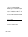
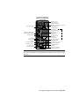
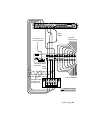
1
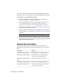
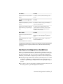
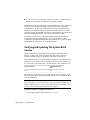
Autodesk
Lustre 2011
®
®
A Discreet systems product
®
HP xw8400 Workstation
Hardware Setup Guide
Autodesk® Lustre® 2011
©
2010 Autodesk, Inc. All rights reserved. Except as otherwise permitted by Autodesk, Inc., this publication, or
parts thereof, may not be reproduced in any form, by any method, for any purpose.
Certain materials included in this publication are reprinted with the permission of the copyright holder.
Trademarks
The following are registered trademarks or trademarks of Autodesk, Inc., and/or its subsidiaries and/or affiliates in the USA and other countries:
3DEC (design/logo), 3December, 3December.com, 3ds Max, Algor, Alias, Alias (swirl design/logo), AliasStudio, Alias|Wavefront (design/logo),
ATC, AUGI, AutoCAD, AutoCAD Learning Assistance, AutoCAD LT, AutoCAD Simulator, AutoCAD SQL Extension, AutoCAD SQL Interface,
Autodesk, Autodesk Envision, Autodesk Intent, Autodesk Inventor, Autodesk Map, Autodesk MapGuide, Autodesk Streamline, AutoLISP, AutoSnap,
AutoSketch, AutoTrack, Backburner, Backdraft, Built with ObjectARX (logo), Burn, Buzzsaw, CAiCE, Civil 3D, Cleaner, Cleaner Central, ClearScale,
Colour Warper, Combustion, Communication Specification, Constructware, Content Explorer, Dancing Baby (image), DesignCenter, Design
Doctor, Designer's Toolkit, DesignKids, DesignProf, DesignServer, DesignStudio, Design Web Format, Discreet, DWF, DWG, DWG (logo), DWG
Extreme, DWG TrueConvert, DWG TrueView, DXF, Ecotect, Exposure, Extending the Design Team, Face Robot, FBX, Fempro, Fire, Flame, Flare,
Flint, FMDesktop, Freewheel, GDX Driver, Green Building Studio, Heads-up Design, Heidi, HumanIK, IDEA Server, i-drop, ImageModeler, iMOUT,
Incinerator, Inferno, Inventor, Inventor LT, Kaydara, Kaydara (design/logo), Kynapse, Kynogon, LandXplorer, Lustre, MatchMover, Maya,
Mechanical Desktop, Moldflow, Moonbox, MotionBuilder, Movimento, MPA, MPA (design/logo), Moldflow Plastics Advisers, MPI, Moldflow
Plastics Insight, MPX, MPX (design/logo), Moldflow Plastics Xpert, Mudbox, Multi-Master Editing, Navisworks, ObjectARX, ObjectDBX, Open
Reality, Opticore, Opticore Opus, Pipeplus, PolarSnap, PortfolioWall, Powered with Autodesk Technology, Productstream, ProjectPoint, ProMaterials,
RasterDWG, RealDWG, Real-time Roto, Recognize, Render Queue, Retimer, Reveal, Revit, Showcase, ShowMotion, SketchBook, Smoke, Softimage,
Softimage|XSI (design/logo), Sparks, SteeringWheels, Stitcher, Stone, StudioTools, ToolClip, Topobase, Toxik, TrustedDWG, ViewCube, Visual,
Visual LISP, Volo, Vtour, Wire, Wiretap, WiretapCentral, XSI, and XSI (design/logo).
FFmpeg is a trademark of Fabrice Bellard, originator of the FFmpeg project.
All other brand names, product names or trademarks belong to their respective holders.
Disclaimer
THIS PUBLICATION AND THE INFORMATION CONTAINED HEREIN IS MADE AVAILABLE BY AUTODESK, INC. “AS IS.” AUTODESK, INC. DISCLAIMS
ALL WARRANTIES, EITHER EXPRESS OR IMPLIED, INCLUDING BUT NOT LIMITED TO ANY IMPLIED WARRANTIES OF MERCHANTABILITY OR
FITNESS FOR A PARTICULAR PURPOSE REGARDING THESE MATERIALS.
Published by: Autodesk, Inc.
111 Mclnnis Parkway
San Rafael, CA 94903, USA
Title:
Autodesk Lustre 2011 HP xw8400 Workstation Hardware Setup Guide
Document Version:
1
Date:
April 1, 2010
Contents
Chapter 1
Introduction . . . . . . . . . . . . . . . . . . . . . . . . . . . . 1
About This Guide . . . . . . . . . . . . . . . . . . . . . . . . . . . . . . 1
The Lustre Workgroup . . . . . . . . . . . . . . . . . . . . . . . . . . . 2
Lustre Workstation Features . . . . . . . . . . . . . . . . . . . . . 3
Optional Lustre Components . . . . . . . . . . . . . . . . . . . . . . . 4
Typical Configuration Overview . . . . . . . . . . . . . . . . . . . . . . 4
Workflow for Hardware Setup and Application Installation . . . . . . . . 5
Related Documentation . . . . . . . . . . . . . . . . . . . . . . . . . . 6
Hardware Configuration Guidelines . . . . . . . . . . . . . . . . . . . . 7
Verifying and Updating The System BIOS Version . . . . . . . . . . 8
Verifying BIOS Settings . . . . . . . . . . . . . . . . . . . . . . . 10
Restoring BIOS to Default Factory Settings . . . . . . . . . . . . . 11
Verifying and Updating the Graphics Card Driver . . . . . . . . . 11
Ensuring Proper Environmental Conditions . . . . . . . . . . . . 12
Power and Air Conditioning Requirements . . . . . . . . . . . . 13
Avoiding Damage from Static Electricity . . . . . . . . . . . . . . 13
Grounding Hardware Components . . . . . . . . . . . . . . . . . 14
Receiving Your Lustre System . . . . . . . . . . . . . . . . . . . . 14
Notation Conventions . . . . . . . . . . . . . . . . . . . . . . . . . . 14
Contacting Customer Support . . . . . . . . . . . . . . . . . . . . . . 15
Chapter 2
Connecting Peripherals . . . . . . . . . . . . . . . . . . . . . . 17
Workflow for Connecting Peripherals . . . . . . . . . . . . . . . . . . 17
iii
Connection Diagram for the HP xw8400 . . . . . . . . . . . . .
Connecting the Monitor . . . . . . . . . . . . . . . . . . . . .
Connecting the Keyboard, Mouse, and Monitor Calibration
Device . . . . . . . . . . . . . . . . . . . . . . . . . . . . . .
Connecting Storage . . . . . . . . . . . . . . . . . . . . . . . .
Storage for Windows-Based Workstations . . . . . . . . .
Storage for Linux-Based Workstations . . . . . . . . . . .
Network Connections . . . . . . . . . . . . . . . . . . . . . . .
Infiniband Network Support for Lustre on Windows-based
Workstations . . . . . . . . . . . . . . . . . . . . . . . .
4-Port Broadcom Adapter . . . . . . . . . . . . . . . . . .
Integrated Network Adapter . . . . . . . . . . . . . . . .
Chapter 3
. . . . 18
. . . . 20
.
.
.
.
.
.
.
.
.
.
.
.
.
.
.
. 21
. 21
. 22
. 22
. 22
. . . . 22
. . . . 29
. . . . 29
Connecting System Components . . . . . . . . . . . . . . . . . 31
Workflow for Connecting System Components in the Lustre
Workgroup . . . . . . . . . . . . . . . . . . . . . . . . . . . . .
Connecting the Autodesk Control Surface . . . . . . . . . . . . .
Assigning an IP Address to the Autodesk Control Surface . . . . .
Configuring Lustre to Connect to the Autodesk Control Surface .
Connecting a Stand-Alone Tablet . . . . . . . . . . . . . . . . . .
Connecting the Slave Renderer to a Lustre Workstation . . . . . .
Connecting Video I/O to a Master or HD Station . . . . . . . . .
Video I/O for Real-Time Deliverables and Without Real-Time
Deliverables . . . . . . . . . . . . . . . . . . . . . . . . .
Video I/O without Real-Time Deliverables . . . . . . . . . .
Setting Up VTR Emulation . . . . . . . . . . . . . . . . . . . . .
VTR Emulation RS-422 Control Cables . . . . . . . . . . . .
Connecting to a High-Speed Data Link Device (HSDL) . . . . . .
Connecting Audio Hardware . . . . . . . . . . . . . . . . . . . .
Audio Wiring Workflow . . . . . . . . . . . . . . . . . . . .
Audio Hardware Components . . . . . . . . . . . . . . . .
Understanding Local Control of the Lucid Converter . . . .
Audio Wiring . . . . . . . . . . . . . . . . . . . . . . . . .
Configuring the Lucid ADA 88192 Converter . . . . . . . .
.
.
.
.
.
.
.
.
.
.
.
.
.
.
. 31
. 32
. 35
. 38
. 38
. 39
. 40
.
.
.
.
.
.
.
.
.
.
.
.
.
.
.
.
.
.
.
.
.
.
. 41
. 43
. 45
. 45
. 46
. 47
. 47
. 47
. 48
. 48
. 50
Index . . . . . . . . . . . . . . . . . . . . . . . . . . . . . . . . 53
iv | Contents
Introduction
1
Topics in this chapter:
■
■
■
■
■
■
■
■
■
About This Guide on page 1
The Lustre Workgroup on page 2
Optional Lustre Components on page 4
Typical Configuration Overview on page 4
Workflow for Hardware Setup and Application Installation on page 5
Related Documentation on page 6
Hardware Configuration Guidelines on page 7
Notation Conventions on page 14
Contacting Customer Support on page 15
About This Guide
This guide describes how to set up the HP® xw8400 workstation and the other
hardware components of your Autodesk® Lustre® 2011 workgroup. The HP
xw8400 workstation is available for Lustre systems on Windows®, as well as for
Autodesk® Incinerator® Lustre systems on Linux®. To install and configure
hardware and software components, use this guide in conjunction with the
following documents: the Autodesk Lustre Installation and Configuration Guide
for Windows Workstations, and the Autodesk Incinerator Installation and User Guide
for Lustre with Incinerator.
1
NOTE In most cases, both hardware setup and application installation are done
on delivery by an authorized technician, so you may not need to perform some
of the procedures in these guides.
The latest versions of all guides are available in PDF format from the Web at
http://www.autodesk.com/lustre-documentation. For best results viewing and
printing these PDF files, use Adobe® Acrobat® Reader™ 6 or later, or Xpdf
viewer.
NOTE If you do not have Acrobat Reader, you can download a free copy from
the Adobe Web site (http://www.adobe.com). If you do not have Xpdf viewer, you
can download a free copy from the Xpdf Web site (http://www.foolabs.com/xpdf/).
The Lustre Workgroup
Lustre is a modular system that you can configure and expand to suit your
needs. The features you purchase determine the hardware included with your
system.
Central to any system is the Master Station or HD Station. The Master Station
is a high-end Windows- or Linux-based PC designed to accommodate real-time
interactivity in a client-attended or supervised session. You can add a Lustre
Station to improve the efficiency of your pipeline.
Master Station Includes the full Lustre toolset and is designed for
GPU-accelerated sessions where the colorist works together with the
cinematographer. Contains an extensive creative toolset for more elaborate
visual design and grading using up to 4K resolution and 16-bit files and for
completing tasks like dust busting, conforming, rotoscoping and
capture/playout.
HD Station Cost-effective GPU workstation for conforming, preparing,
grading and mastering short-form and long-form HDTV projects, as well as
HD film projects. Input up to 10-bit 2K and output HD and SD.
Lustre Station Tasks that do not require the direct intervention or supervision
of the colorist can be efficiently handled by a Lustre Station. Multiple Lustre
Stations can work in parallel to increase throughput and can be used for tasks
such as dust-busting, preparatory work, fine-tuning creative sessions,
conforming data from EDLs, updating editorial changes using change lists,
and mastering to different formats using the real-time deliverables function.
2 | Chapter 1 Introduction
Lustre Workstation Features
The following table describes the features available to each Lustre workstation.
NOTE The features of Lustre 2011 may vary based on your hardware platform.
Consult the Autodesk 2011 Release Notes for your release for specific system
information.
Station
Configuration
Master Station
Default All features are available including SD and HD I/O, dual
link and HSDL video formats and the DI Pack, which consists of infrared channel dust removal and support for all standard input and
output resolutions and bit-depths. Certain features require add-on
licensing.
Add-Ons The following features can be added to the Default configuration: the Slave Renderer and up to three panels for the Autodesk
control surface. The Slave Renderer requires a separate license.
Lustre HD Station
Default Includes all features except for the DI Pack (see the Master
Station description). File input is limited to 2K resolution. File output
is limited to HD resolution, 10-bit. Certain features require add-on licensing.
Add-Ons The following features can be added to the Default configuration: SD and HD I/O, dual link and HSDL video formats, the
Slave Renderer, and up to three panels for the Autodesk control surface. The Slave Renderer requires a separate license.
Lustre Station
Default All features are available except for primary and secondary
colour grading. The DI Pack (see the Master Station description) is
also included, along with full dust removal functionality, and the
ability to create geometries and masks.
With Primary Colour Correction Includes all features of the default
option as well as primary colour grading.
Add-Ons The following features are available for either the Default
configuration or the With Primary Colour Correction configuration,
and require an additional license: SD and HD I/O, dual link and HSDL
video formats, and up to three panels for the Autodesk control surface.
The Slave Renderer requires a separate license.
Lustre Workstation Features | 3
Optional Lustre Components
You can expand the features of your Lustre system and improve the efficiency
of your workflow by adding any of the following components.
Control Surface The Autodesk control surface provides improved interactivity
when colour grading film and video footage. You can perform many of the
same tasks you do in the Lustre user interface using the control surface.
Video I/O Video I/O is provided by the DVS Centaurus® board, which consists
of an HD/SD board and a breakout box. This configuration provides real-time
SDI input and output of uncompressed 8- or 10-bit HD or SD video in both
YUV (4:2:2) and RGB formats (4:4:4 or 4:2:2).
For a list of supported video formats, see the Autodesk Lustre 2011 User Guide.
Audio I/O Audio I/O is provided by the DVS Centaurus board, which consists
of an HD/SD board and a breakout box, and an ADAT Converter such as the
Lucid ADA 88192. This configuration offers eight audio input and eight audio
output channels. They all use 24-bit audio resolution.
Slave Renderer The Slave Renderer is a rack-mounted server that is connected
directly to the Lustre workstation. It frees system resources by off-loading
render tasks on an 'as-needed' basis, thus ensuring real-time interaction on
the Lustre system.
Background Renderer Background rendering frees up Lustre workstations
for colour grading. You can use up to eight background rendering machines
to process your final frames.
NOTE For a list of Incinerator system components, refer to the Autodesk Incinerator
2011 Installation and User Guide
Typical Configuration Overview
The following illustration shows a typical configuration, including the Master
Station, Lustre Station, and other optional components.
4 | Chapter 1 Introduction
Control Surface
R
Grade
InPr
Curve
OutPr
K ey
C URVES
GRADE
KEY
Geom
G EOM
G
Hue
BBrigh t
0019
#0001.00
Misc
P&S Outside
Inside
P &S
IN
MISC
OUT
High
Brigh t Sh Mid
Brigh tness
Satur ation
R+ G+
B+ +
R- GB- -
Shadow
Contr ast
MORE
F2
F1
Brigh tness
F5
F4
F3
F6
MORE
F8
F7
F9
Lustre Master Workstation
DO
REDO
UNDO
CURSOR
REVERT
RECALL
COMP
OFFSET
CLIP
7
8
9
4
5
6
1
2
3
0
.
+/-
GRADE
A/B
Wipe
Multi
Matt e
ENTER
O/P
Spli t
Stil l
Proxy
ALT
CUE
ALT
AJA BOB (breakout box)
Out
In
Out
Audio
Out
Wclk CVBS
1/2
3/4
5/6
7/8
1/2
3/4
5/6
7/8
RS422A
GPI
RS422B
In
LTC
Out
Peripheral Options
Network Options
Slave Renderer
Lustre Storage
Background Rendering (Burn)
SAN options
Lustre Station
Stone Shared
In
Out
Audio
Out
Wclk CVBS
Out
1/2
3/4
5/6
7/8
1/2
3/4
5/6
7/8
RS422A
GPI
RS422B
LTC
In
Out
Video I/O
NOTE For an Incinerator system configuration overview, refer to the Autodesk
Incinerator 2011 Installation and User Guide.
Workflow for Hardware Setup and
Application Installation
The following procedure provides the general workflow for installing Lustre
on an HP xw8400 workstation running Windows.
Workflow for Hardware Setup and Application Installation | 5
For workflow information related to the HP xw8400 running on Linux for
Incinerator, refer to the Autodesk Incinerator 2011 Installation and User Guide.
To install Lustre on an HP xw8400 workstation:
1 Review the guidelines for working with hardware components. See
Hardware Configuration Guidelines on page 7.
2 Connect all peripherals (mouse, keyboard, graphics monitor, storage,
etc.) to each workstation in your workgroup, and connect each
workstation to the network. See Connecting Peripherals on page 17.
3 Connect your workstation to Autodesk® Stone® Direct storage. See the
Installation and Configuration Guide.
4 Connect your Master or HD Station to a Slave Renderer, a control surface,
tablet, and video I/O components. See Connecting System Components
on page 31.
NOTE The Slave Renderer is not used in Incinerator configurations.
5 Perform the procedures in the Autodesk Lustre 2011 Software Installation
Guide or the Autodesk Incinerator 2011 Installation and User Guide to install
and license Lustre and Incinerator.
Related Documentation
The following table describes the documentation associated with your
application. For a detailed list of the latest documentation, see your release
notes.
User Guides
Provides
Autodesk Lustre 2011 User Guide
Detailed instructions on using the software.
Autodesk Control Surface User Guide
Detailed instructions on using the Autodesk
control surface and the Tangent CP100.
Autodesk Lustre 2011 New Features
Guide
A list of the new features for this release.
Autodesk Lustre 2011 Hot Keys Card
A list of the most frequently used hot keys.
Autodesk Lustre 2011 Release Notes
A complete list of documentation and information on late-breaking features.
6 | Chapter 1 Introduction
User Guides
Provides
Autodesk Lustre 2011 Fixed and Known
Bug List
A complete list of fixed and known bugs for this
release.
Installation and Configuration
Guides
Provides
Hardware Setup Guide (for your workstation)
Information on how to set up your workstation
and video I/O peripherals.
Autodesk Lustre Installation and Configuration Guide (for your operating system)
Information about installing and licensing
yourAutodesk Lustre software. Note: For Lustre
and Incinerator, see the Autodesk Incinerator
Installation and User Guide.
Other Guides
Provides
Autodesk Lustre Sparks API Reference
Guide
Instructions for developing Sparks® plugins for
Lustre.
Autodesk Backburner 2011 Installation Guide
Autodesk Backburner 2011 User Guide
Information on how to install, set up, and use
Autodesk® Backburner™.
Consult the Autodesk Web site at http://www.autodesk.com/lustre-documentation
for the latest version of guides, release notes, and fixed and known bugs
documents.
Hardware Configuration Guidelines
In most cases, hardware integration and application installation is done on
delivery by an authorized technician, and some of the procedures in this guide
may not be necessary. Still, it is a good idea to read through all chapters to
familiarize yourself with the configuration procedures for the following reasons:
■
Many suspected problems with your Lustre system may be due to loosened
connections or improperly configured devices. This guide helps you
troubleshoot problems by providing information about properly configured
systems.
■
If you need to call Customer Support, familiarity with this guide puts you
in a better position to provide diagnostic information.
Hardware Configuration Guidelines | 7
■
If you want to move your Lustre system at any time, or upgrade certain
hardware components, information in this guide is crucial.
Although this guide, in conjunction with the Installation and Configuration
Guide, provides complete information regarding hardware component
configuration, it should only be undertaken by an experienced hardware
integrator. This individual should be familiar with the Windows or Linux
operating systems, HP xw8400 workstations, and peripherals associated with
professional high-performance video and post production of film.
Your Lustre system consists of high-performance hardware that must be
configured in an environment suited to its operational needs. Other
considerations include minimizing the risk of damage due to static discharge
and ensuring all components are properly grounded.
Verifying and Updating The System BIOS
Version
System configuration is performed by an authorized technician prior to
delivery. As such, some of the procedures here may not be necessary.
Workstation BIOS settings are provided for informational purposes.
The system BIOS on your workstation must correspond to the certified version
required by your software version. If the BIOS version on your system does
not correspond to the table below, you must update to the certified version.
Product Version
Certified BIOS Version
2011
2.26
The BIOS version installed on your system appears onscreen while booting
the workstation. The following procedures describe how to update the BIOS
on your workstation.
WARNING You should only update the BIOS if you find that it is not at the version
listed in this guide, or if your are advised to do so by Customer Support. Do not
update the BIOS with a more recent version published by the hardware vendor,
if it has not been certified by Autodesk Customer Support.
To update the BIOS on a Windows workstation:
1 Get the BIOS upgrade utility and burn it to a CD.
8 | Chapter 1 Introduction
2 Insert the CD into the CD-ROM drive
3 Reboot the workstation and press F10 to enter BIOS.
4 Select a language.
5 From the File menu, select Flash System ROM.
The Select a Drive menu appears.
6 Click Optical Drive.
The Select a Drive confirmation menu appears.
7 Press F10 to confirm.
8 Select the 7D5_0115.bin file.
The Flash® System ROM confirmation menu appears.
9 Press F10 to confirm.
10 Press any key.
System ROM Flash was successful appears.
11 Verify system BIOS settings. See Verifying BIOS Settings on page 10.
12 From the File menu, select Save Changes and Exit.
To update the BIOS on a Linux workstation:
1 Load the DKU CD in the DVD-ROM drive on the workstation.
2 Open a terminal.
3 Type:
cd /mnt/cdrom/Utils/BIOS/
Each supported platform has its own directory that contains an .iso file.
NOTE For more information about updating the BIOS on your workstation,
refer to the README file located in your platform's directory.
4 Type:
cd ./<platform>
5 Burn the .iso file for your platform onto a CD-ROM and place it in the
DVD-ROM drive on the workstation.
6 Reboot the workstation and press F10 to enter BIOS.
Verifying and Updating The System BIOS Version | 9
7 Select a language.
8 From the File menu, select Flash System ROM.
The Select a Drive menu appears.
9 Click Optical Drive.
The Select a Drive confirmation menu appears.
10 Press F10 to confirm.
11 Select the 7D5_0115.bin file.
The Flash System ROM confirmation menu appears.
12 Press F10 to confirm.
13 Press any key.
System ROM Flash was successful appears.
14 Verify system BIOS settings. See Verifying BIOS Settings on page 10.
15 From the File menu, select Save Changes and Exit.
Verifying BIOS Settings
You do not normally need to adjust BIOS settings on your workstation. BIOS
settings for the workstation are provided here for informational purposes only.
To enter the system BIOS, press F10 while booting the workstation.
WARNING Before installing Red Hat® Linux, it is recommended that you verify
the workstation's BIOS settings. If the storage SATA emulation option is not set
correctly (to Separate IDE Controller), you must redo Red Hat Linux installation.
The following table lists the proper Autodesk certified BIOS settings. Items
not listed are set to their default factory settings.
BIOS Menu
Item
Value
Storage, Storage options
SATA Emulation
Separate IDE Controller
Storage
Boot Order
Optical Drive USB
Device Hard Drive,
Integrated SATA
10 | Chapter 1 Introduction
BIOS Menu
Item
Value
Hard Drive, Integrated IDE
Storage, Power, OS Power Management
Runtime Power
Management
Disabled
Storage, Power, OS Power Management
Idle Power Savings
Normal
Storage, Power, OS Power Management
ACPI S3 Support
Disabled
Storage, Advanced, Device Options
S5 Wake on LAN
Disabled
Advanced
Slot5 - PCI 133
Slot5 speed
100Mhz PCI-x m1
Restoring BIOS to Default Factory Settings
The following procedure restores the default factory BIOS settings.
To restore default factory BIOS settings:
1 Press F10 while booting the workstation to enter the system BIOS.
2 From the File menu select Default setup | Restore Factory
Settings as Default.
3 Press F10 to accept the changes.
4 Select Apply Defaults and Exit.
This restores the original factory system defaults.
Verifying and Updating the Graphics Card
Driver
A new graphic driver (NVIDIA® driver 165.46) is required for Lustre 2011
Windows systems. To upgrade the NVIDIA graphics card driver, complete the
following instructions.
Restoring BIOS to Default Factory Settings | 11
To upgrade the NVIDIA graphics driver:
1 Copy the driver upgrade package located in the Lustre 2011 release
package (Drivers\Nvidia\165.46.zip) to a temporary location on your
system.
2 Use a compression utility, like Winzip, to decompress the driver upgrade
package and extract it to a folder on your system.
3 Open the folder that contains the upgrade package you extracted and
double-click setup.exe to start the driver update.
4 Click Next to continue the upgrade procedure.
A Hardware Installation warning message appears.
5 Click Continue Anyway.
6 Select Yes, I want to restart my computer now, and click Finish.
After you reboot, the NVIDIA graphics card driver is installed.
Ensuring Proper Environmental Conditions
You should consider the following environmental guidelines for all hardware
configuration:
■
Make sure the rack in which hardware components are installed is open
or ventilated. Follow the ventilation specifications that apply to your
system.
■
Place all components in an air-conditioned environment. All hardware
components generate heat and must be kept cool. See Power and Air
Conditioning Requirements on page 13.
■
Keep all hardware components in a clean, dust-free location.
■
Minimize vibration and humidity.
■
Do not block the vents on the component housing.
■
Do not drape anything, such as a jacket or a blanket, over hardware
components.
■
Minimize electromagnetic noise by separating digital data and power cables
from analog audio cables and running them in different cable ducts.
12 | Chapter 1 Introduction
Power and Air Conditioning Requirements
The values for power consumption and heat output were recorded on an
Autodesk certified system with all of the required peripheral and certified
components.
NOTE These values can fluctuate if uncertified hardware components or third-party
applications are added to your system. The use of uncertified hardware components
or third-party applications is not supported. Please consult the manufacturer's
documentation for standardized minimum and maximum values.
The following table summarizes the power consumed by the HP xw8400
system and the heat it generates under the maximum processing load produced
by your Lustre application. For detailed specifications, including noise output,
see the documentation provided by the manufacturer.
Component
Quantity Startup Amps
(120V / 240V)
Max. Amps
Watts
(120V / 240V)
Heat
(BTUs)
HP xw8400
1
2.8 / 1.4
1146.4
3.5 / 1.8
336
You must be able to meet the startup power requirement and have a climate
control system with the capacity to maintain the temperature of this
component under the maximum processing load. Refer to the following table
for standard conversion benchmarks and an example of how they are used to
establish climate control requirements.
Unit Conversion
Example
1 Watt = 3.413 BTU
480 Watts = 1638 BTU
12000 BTU = 1 Ton of air
conditioning
1638 BTU = 0.137 Ton of air conditioning
Avoiding Damage from Static Electricity
When installing any hardware equipment, take the following precautions to
prevent damage to sensitive components from static discharge:
■
Make sure power is turned off on the component you are working on. It
is a good idea to unplug components until all other connections are
configured.
Power and Air Conditioning Requirements | 13
■
Always wear a grounded static wrist strap. Attach the strap's alligator clip
to any grounded metal surface on the component's chassis that you are
working on. Place the wristband around your wrist.
■
Do not handle any components unnecessarily, particularly boards and
cards that slide in and out of slots on their parent hardware components.
Grounding Hardware Components
It is important to properly ground any audio components used with Lustre
to avoid ground loops and humming. To ensure audio components are properly
grounded, use the XLR-3 cables. Using any other cables may cause humming
in the system.
Receiving Your Lustre System
When you receive the shipment containing your Lustre, check all the boxes
for dents or other markings that may indicate damage during transport. If you
suspect a component is damaged, carefully inspect it before setting up the
system. If you receive a damaged component, call Customer Support.
Use the enclosed packing checklist to ensure you received all parts.
Notation Conventions
A number of style conventions are used throughout this guide. These
conventions and examples of their use are shown as follows.
Convention
Example
Text that you enter in a command line or shell appears
in Courier bold. You must press the Enter key after each
command.
rpm -qa
Variable names appear in Courier, enclosed in angle
brackets. No spaces are allowed in variable names.
<variable_name>
Variables that appear enclosed in square brackets are
optional.
[<filename>]
Feedback from the command line or shell appears in
Courier.
limit coredumpsize
14 | Chapter 1 Introduction
Convention
Example
Directory names, filenames, URLs, and command line
utilities appear in italics.
/usr/discreet
Contacting Customer Support
A list of contact information for Autodesk Media and Entertainment Customer
Support is available at www.autodesk.com/support.
Customer support is also available through your Autodesk reseller. To find a
reseller near you, consult the reseller look-up database on the Autodesk web
site at www.autodesk.com/resellers.
Contacting Customer Support | 15
16
2
Connecting Peripherals
Topics in this chapter:
■
■
■
■
■
■
Workflow for Connecting Peripherals on page 17
Connection Diagram for the HP xw8400 on page 18
Connecting the Monitor on page 20
Connecting the Keyboard, Mouse, and Monitor Calibration Device on page 21
Connecting Storage on page 21
Network Connections on page 22
Workflow for Connecting Peripherals
You must connect peripherals (monitor, keyboard, mouse, storage, and network)
to each Lustre workstation before you connect the workstations to video I/O,
a control surface, or to other components in the workgroup.
Connect all hardware peripherals before you boot your workstation.
See the following table for a summary of the steps necessary to connect
peripherals to your Lustre workstation.
Step:
Refer to:
1. Review the connection diagram for your workstation.
Connection Diagram for the HP
xw8400 on page 18.
17
Step:
Refer to:
2. Connect a monitor to the workstation.
Connecting the Monitor on
page 20.
3. Connect a keyboard, mouse, and calibration device
to your workstation.
Connecting the Keyboard,
Mouse, and Monitor Calibration Device on page 21.
4. Connect the workstation to storage.
Connecting Storage on page
21.
5. Connect the workstation to your network.
Network Connections on page
22.
6. After you connect all the peripherals to your Lustre
workstations, you can connect the workgroup components together.
Connecting System Components on page 31.
Connection Diagram for the HP xw8400
The following diagrams show the connections for the HP xw8400 workstation.
NOTE These diagrams provide an overview of video I/O connections. See
Connecting Video I/O to a Master or HD Station on page 40.
18 | Chapter 2 Connecting Peripherals
HPxw8400 Workstation
(Windows Configuration)
HD-SDI ( V2) Out
0:2:2/4:0:0 t o 4:4:4
display device or VTR
Ref In from sync gen
HD-SDI ( V1) Out 4:2:2 t o 4:2:2 or 4:4:4
display device or VTR
Connect to second
DVI out on the
main FX5500 card
To USB extender for mouse
keyboard, monitor calibrator
To Slave Renderer
To DVS BOB
To GFX monitor
To storage
1, 4 to SAN; 2, 3 to Stone
Ref In from sync gen
0 to control surface,
1 to LAN, 3 to SAN
HD-SDI Out (B) t o
4:4:4 VTR
(dual link 0:2:2)
HD-SDI In (B) from
4:4:4 VTR
(dual link 0:2:2)
DV12 Out to FX5500
SDI daughter card
HD-SDI Out (A) t o 4:2:2
VTR (or 4:4:4 dual link)
To InfiniBand switch
(optional)
HD-SDI In (A) from 4:2:2
VTR (or 4:4:4 dual link)
NOTE Systems connected to the high-speed InfiniBand network may experience
performance degradation if high bandwidth is requested on the Broadcom GigE
card (slot 7).
Connection Diagram for the HP xw8400 | 19
HPxw8400Workstation
(Linux - Incinerator only)
HD-SDI ( V2) Out
0:2:2/4:0:0 t o 4:4:4
display device or VTR
HD-SDI ( V1) Out 4:2:2 t o 4:2:2 or 4:4:4
display device or VTR
To USB extender for mouse,
keyboard, monitor calibrator
To Incinerator
GigE switch
To DVS BOB
To GFX monitor
To InfiniBand
switch
Ref In from sync gen
0 t o co n t rol su rface,
1 t o LAN , 3 t o SAN
Ref In f rom sync gen
Connect to second
DVI out on the
main FX5500 card
HD-SDI Out (B) t o
4:4:4 VTR
(dual link 0:2:2)
HD-SDI In (B) from
4:4:4 VTR
(dual link 0:2:2)
DVI2 Out t o FX5500
SDI daughter card
HD-SDI Out (A) t o 4:2:2
VTR (or 4:4:4 dual link)
HD-SDI In (A) f rom 4:2:2
VTR (or 4:4:4 dual link)
NOTE The Slave Renderer option is not available for Lustre with Incinerator.
Connecting the Monitor
Connect the monitor to the DVI connection on the Lustre workstation's
graphics card. You can use the DVI extender cable (DL.CAB-HDTV-FO-82-MM)
to extend the cable to a machine room.
To connect the monitor:
➤
Use the DVI cable to connect the DVI OUT1 port of the NVIDIA® Quadro®
FX5500 graphics card to the DVI-D IN port of the monitor.
NOTE Although the DVI fiber cable connectors are identical, their functions
are different. Ensure that the connector labeled Send is connected to the
Lustre workstation, and that the connector labeled Receive is connected to
the monitor.
20 | Chapter 2 Connecting Peripherals
Connecting the Keyboard, Mouse, and
Monitor Calibration Device
Connect the mouse, keyboard, and monitor calibration device to the
workstation via the 4-port USB extender (TP.USB-EXT-400).
To connect the keyboard and mouse:
1 Connect the USB keyboard to port 2 on the remote unit of the USB
extender.
2 Connect the USB mouse to port 3 on the remote unit of the USB extender.
3 Connect the monitor calibration device (TP.MON-CAL-LCDCRT) to port
4 on the remote unit of the USB extender.
4 Use an RJ-45 cable to connect the remote unit of the USB extender to the
local unit of the USB extender.
5 Connect the local unit of the USB extender to USB1 port on the
workstation.
To enable the Eye-One calibration utility driver:
➤
Do one of the following:
■
For Windows-based workstations, if the driver is not already installed,
you will be prompted to install the monitor calibration device driver
when you restart the workstation. The driver is available from the
C:\Program Files\Autodesk\Lustre Color 2008 SP3\Calibration\drivers
directory.
■
For Linux workstations, once the software installation has been
completed, start the eyeone27 daemon on the workstation. Type:
/etc/init.d/eyeoned_2011 start
Connecting Storage
The storage connections for your system depend on whether you are running
Lustre on the Windows or Linux operating system.
Connecting the Keyboard, Mouse, and Monitor Calibration Device | 21
Storage for Windows-Based Workstations
Your workstation is configured with a 4-port ATTO Celerity FC-44ES fibre
channel adapter. See Connection Diagram for the HP xw8400 on page 18for
the fibre channel adapter location and connections.
You can connect your workstation to two types of storage:
■
One or more Stone Direct disk arrays that provide storage to individual
workstations.
■
A Storage Area Network (SAN) that provides shared storage for multiple
workstations.
Storage for Linux-Based Workstations
Lustre systems on Linux are used in conjunction with Incinerator and do not
require local storage. Instead, your workstation is configured with an Infiniband
9000 DDR dual port HCA, which allows it to connect to the Incinerator
high-speed Infiniband network.
Refer to the Autodesk Incinerator Installation and User Guide for information on
how to connect your workstation to the Incinerator high-speed Infiniband
network.
Network Connections
Your workstation is configured with a 4-port Broadcom network card, and an
integrated network port.
Infiniband Network Support for Lustre on
Windows-based Workstations
Lustre supports the use of an Infiniband network for HP xw8400 workstations
running Windows XP SP2. The workstation must have the required Infiniband
driver installed.
NOTE Real-time playback using the Infiniband support in Windows is limited to
24 frames per second HD at 1920x1080 resolution with an 8-bit bit depth from
Wiretap clips loaded from Autodesk® Smoke® or Autodesk® Flame®.
22 | Chapter 2 Connecting Peripherals
When the Infiniband topology (including driver) is fully installed, Autodesk
recommends adjusting specific configuration parameters in the Windows
operating system to optimize performance.
To install the Infiniband driver for use with a Windows-based Lustre
workstation:
1 Download the driver package to a temporary location on your system.
You can find the appropriate driver package here:
ftp://ftp.discreet.com/pub1/release/lustre/lustre2008/drivers/SilverStormHCA.msi
NOTE Contact Customer Support if you have any problems downloading
the driver package. See Contacting Customer Support on page 15.
2 Double-click the driver package and click Run.
The SilverStorm HCA Setup Wizard opens.
Click Next.
3 On the License Agreement page, read the agreement before selecting the
I Agree radio button. Click Next.
4 On the SilverStorm HCA Information page, read through the driver
manufacturer Release Notes, then click Next.
Infiniband Network Support for Lustre on Windows-based Workstations | 23
5 On the Installation Options page, make sure no optional components
are checked, then click Next.
6 On the Select Installation Folder page, browse for the correct path in
which to install the driver.
24 | Chapter 2 Connecting Peripherals
7 Choose the system user permissions by selecting either the Everyone
radio button or the Just me radio button. Click Next.
8 On the Confirm Installation page, click Next to begin the installation.
The wizard displays an installation progress bar.
9 On the Installation Complete page, click Close.
10 On the Windows Desktop, right-click My Computer and select Properties
in the drop-down menu.
The System Properties dialog box appears.
11 Click the Hardware tab.
12 Click Device Manager.
The Device Manager dialog box appears.
13 Right-click the PCI Device under Infiniband Host Channel Adapters.
The Hardware Update Wizard appears.
14 Select No and click Next.
15 Select Install from a list or specific location and click Next.
16 Browse for the driver and click Next.
17 Click Finish.
The driver and interface install.
18 In the Device Manager dialog box, right-click the first Infiniband port
adapter.
Infiniband Network Support for Lustre on Windows-based Workstations | 25
NOTE There are two Infiniband port adapters. In the Device Manager, at
this point, the adapters should each be indicated by the adapter icon with
an exclamation mark through it. This shows that the adapter drivers are not
yet installed.
The Hardware Update Wizard appears.
19 Select No and click Next.
20 Select Install from a list or specific location and then click Next.
21 Browse for the driver and click Next.
26 | Chapter 2 Connecting Peripherals
22 Click Finish.
The driver and interface install.
Repeat step 19 to step 22 for the second Infiniband port adapter.
The Infiniband Host Channel Adapter and the two IP over IB port adapters
should appear in the Device Manager dialog box, without exclamation
marks on their icons.
To optimize the Infiniband driver on Windows:
NOTE The Infiniband driver optimization steps are optional.
1 Go to the Network Connections panel.
2 Right-click on the connected IPoIB port and select Properties.
3 Click the Advanced tab.
4 Click Configure.
5 Configure the card so you have these values:
■
Receive Queue Depth of 256
Infiniband Network Support for Lustre on Windows-based Workstations | 27
■
Send Queue Depth of 256
28 | Chapter 2 Connecting Peripherals
4-Port Broadcom Adapter
Connect the workstation to your facility's network to access background
rendering nodes, other Lustre Stations, and the facility's NAS or SAN centralized
storage (if applicable). You connect the ports on the Broadcom card as follows:
■
Connect Port 0 to the Autodesk control surface hub or the control surface
itself.
■
Connect Port 1 to your house network.
■
Connect Port 2 to a SAN private network (optional).
For more details about configuring the Autodesk control surface, see
Connecting the Autodesk Control Surface on page 32.
Integrated Network Adapter
For Windows-based workstations, connect the integrated network port to the
Slave Renderer. For more details about configuring the Slave Renderer, see
Connecting the Slave Renderer to a Lustre Workstation on page 39.
For Linux-based workstations, connect the integrated network port to the
Incinerator private port. Refer to the Autodesk Incinerator Installation and User
Guide for information on how to connect your workstation to the Incinerator
private network.
4-Port Broadcom Adapter | 29
30
Connecting System
Components
3
Topics in this chapter:
■
■
■
■
■
■
■
■
■
■
Workflow for Connecting System Components in the Lustre Workgroup on page
31
Connecting the Autodesk Control Surface on page 32
Assigning an IP Address to the Autodesk Control Surface on page 35
Configuring Lustre to Connect to the Autodesk Control Surface on page 38
Connecting a Stand-Alone Tablet on page 38
Connecting the Slave Renderer to a Lustre Workstation on page 39
Connecting Video I/O to a Master or HD Station on page 40
Setting Up VTR Emulation on page 45
Connecting to a High-Speed Data Link Device (HSDL) on page 46
Connecting Audio Hardware on page 47
Workflow for Connecting System
Components in the Lustre Workgroup
After you have connected peripherals to your workstation, you are ready to
connect it to the Autodesk control surface, to video I/O hardware, and to a Slave
Renderer.
31
See the following table for a summary of the steps necessary to connect
components in your workgroup.
Step:
Refer to:
1. Connect the control surface to your
workstation.
For the Autodesk control surface: Connecting
the Autodesk Control Surface on page 32,
Assigning an IP Address to the Autodesk
Control Surface on page 35, and Configuring
Lustre to Connect to the Autodesk Control
Surface on page 38.
2. If necessary, connect a tablet to your
workstation.
Connecting a Stand-Alone Tablet on page
38.
3. Connect a Slave Renderer to the
Lustre workstation (Windows only).
Connecting the Slave Renderer to a Lustre
Workstation on page 39.
4. Connect the workstation to video I/O
components.
Connecting Video I/O to a Master or HD
Station on page 40.
5. Connect the workstation to a highspeed data link device.
Connecting to a High-Speed Data Link Device
(HSDL) on page 46.
6. Connect the workstation to audio I/O
components.
Connecting Audio Hardware on page 47.
Connecting the Autodesk Control Surface
The Autodesk control surface consists of three panels. You can use any
combination of them. If you are using more than one panel, you must use
the network switch included with your shipment to cross-connect them.
Refer to the Autodesk Control Surface User Guide for information on how to use
the control surface with Lustre.
NOTE The illustrations in the following procedure only show the central module,
i.e. the colour grading panel. This is the only panel that has a USB connection for
the integrated tablet, and a network port. The other two panels only have a
network port, which you connect to the network switch.
To connect the Autodesk control surface:
1 Use the AC power adapter cables to connect each panel to a power supply.
32 | Chapter 3 Connecting System Components
2 Use a network cable to connect port 0 (the far right port) of the Broadcom
network card on your workstation to port 1 on the Netgear ProSafe FS108
network switch.
HP xw8600 Workstation
To USB extender
Network Switch
Ports 3 and 4 to
additional panels
NETGEAR
PWR
1
2
3
4
5
6
8
To port 1 on USB Extender
Autodesk
Activit y
Link
Power
Autodesk Control Surface
System
7
Tablet
5V DC 4A
+
Ethernet
-
If you are using only one panel, you can connect that panel directly to
the workstation, instead of using the switch.
Connecting the Autodesk Control Surface | 33
To USB extender
To port 1 on USB Extender
Autodesk
Activit y
Link
System
Power
Autodesk Control Surface
Tablet
5V DC 4A
+
Ethernet
-
3 If you are using more than one panel, use network cables to connect each
of the panels to the network switch.
4 If you are using the panel that includes the tablet, use a USB cable to
connect the panel to a USB port on the back of your workstation.
34 | Chapter 3 Connecting System Components
NOTE The above diagrams represent a Windows-based configuration. Components
may differ slightly for the Linux configuration but the control surface connections
are identical.
Assigning an IP Address to the Autodesk
Control Surface
After you have connected the Autodesk control surface, you must assign it an
IP address.
To configure the Autodesk control surface on Windows-based workstations:
1 Click Start | Settings | Network Connections.
NOTE You can also access Network Connections from the Control Panel.
2 Right-click the port that the control surface switch or panel is connected
to and choose Properties.
3 In the Local Area Connections Properties dialog box, select Internet
Protocol (TCP/IP) and click Properties.
Assigning an IP Address to the Autodesk Control Surface | 35
The Internet Protocol (TCP/IP) Properties dialog box opens.
4 Select the Use the following IP address option.
36 | Chapter 3 Connecting System Components
5 Set a static IP and Subnet mask address for the port. Select values that do
not conflict with any other machine on your network. Consider using
the following values:
■
IP address: 192.168.125.10
■
Subnet mask: 255.255.255.0
6 Click OK twice.
To configure the Autodesk control surface on Linux-based workstations:
➤
On the Lustre workstation, use a text editor such as nedit to configure the
network port connected to the control surface with an unrelated static
IP address that does not interfere with any of the IP addresses on the
network. Also assign an appropriate subnet mask. Type:
nedit
/etc/sysconfig/network-scripts/ifcfg-eth<port#>
Modify the IPADDR and NETMASK values. For example:
IPADDR=192.168.125.10
NETMASK=255.255.255.0
Assigning an IP Address to the Autodesk Control Surface | 37
Configuring Lustre to Connect to the
Autodesk Control Surface
After you have configured the IP address of the control surface, you must
configure Lustre to use the control surface.
To configure Lustre to use the Autodesk control surface on Windows- or
Linux-based workstations:
1 Turn the power on to each of the modules and look at the top display
panel on the module. It should display the panel name and ID.
2 After you install Lustre 2011, open the init.config file located in C:\Program
Files\Autodesk\<lustre version> in Windows, or in /usr/autodesk/<lustre
version> in Linux with a text editor.
3 In the ControlSurface section of the init.config file of your project,
enter the panel IDs for each panel.
ControlSurface
AutodeskPanels state=”On”
PanelIDs function=”0” grading=”0” navigation=”0”
Once the steps above are completed, the ACS panels will be recognized,
loaded, and connected when launching the application.
4 Start Lustre. The following message should appear in the Console:
Panel #<panel_ID> is detected
This confirms that the Autodesk Control Surface is enabled.
Connecting a Stand-Alone Tablet
If you do not have the modular Autodesk control surface panel that includes
the tablet, you can connect a stand-alone tablet.
To connect a stand-alone tablet, connect the tablet to USB Out 1 on the USB
extender.
NOTE On Windows-based workstations, you may need to restart Windows for
the tablet to be recognized. On Linux-based workstations, re-starting the Xserver
prompts tablet recognition. Press Ctrl+Alt+backspace to start the Xserver.
38 | Chapter 3 Connecting System Components
Connecting the Slave Renderer to a Lustre
Workstation
The Slave Renderer is available for the Master Station, the Lustre Station, and
the Lustre HD Station, all of which must be running on a Windows-based
workstation. The Slave Renderer is not available for the Linux-based version
of Lustre, since it uses Incinerator to obtain real-time rendering and playback.
Although the Slave Renderer uses a network connection, a higher Category 6
grade cable is needed to accommodate the data that is transmitted. For
information on configuring the IP addresses of the network ports that connect
the two workstations, see the Autodesk Lustre 2011 Installation and Configuration
Guide for Windows Workstations.
To connect the Slave Renderer to a Windows-based workstation:
1 Connect the Category 6 crossover cable to the on-board network port at
the back of the Lustre workstation.
2 Connect the other end of the cable to the network port 1 of the Slave
Renderer machine.
The Slave Renderer should be connected as shown in the following
diagram.
Connecting the Slave Renderer to a Lustre Workstation | 39
HP xw8600 Workstation
Slave Render Station (HP DL 140 G3)
Port 1
Connecting Video I/O to a Master or HD
Station
You use the video components to set up video I/O and a broadcast monitor.
The only video hardware you must provide are: a sync generator, a VTR, and
an SD or HD SDI broadcast monitor. The following components are included
in your hardware shipment.
40 | Chapter 3 Connecting System Components
DVS Centaurus 1 or 2 board and DVS Breakout Box II The DVS Centaurus
board provides video I/O. Use the DVS Breakout Box II for serial control of a
VTR or other slave device and LTC output to an audio device.
NVIDIA Quadro FX5500 graphics board The NVIDIA Quadro FX graphics
board provides output to your computer monitor.
EIZO 24-inch or Sony 21-inch wide screen LCD graphics monitor The EIZO®
and Sony LCD graphics monitors provide a 16:9 widescreen aspect ratio for
film or HD projects. With these monitors, the application runs at a maximum
resolution of 1920x1200. For instructions on connecting the graphics monitor,
see Connecting the Monitor on page 20.
Altinex DA1804NT video distribution amplifier The Altinex® video
distribution amplifier can serve a bi-level (SD) or tri-level (HD) sync signal to
up to four video hardware devices from a single sync source/generator. It serves
the sync signal to the NVIDIA graphics board and the DVS Centaurus board.
Video I/O for Real-Time Deliverables and
Without Real-Time Deliverables
The following diagram describes the video I/O wiring for both the Real-time
deliverables configuration and without Real-time deliverables. Real-time
deliverables allows Lustre to play out to a VTR directly through the DVS SDI
OUT.
NOTE The backplanes depicted in the following diagram represent a
Windows-based configuration, but, it is also accurate for a Linux-based
configuration, where the ATTO fibre-channel adapter is replaced by the Infiniband
HCA.
Video I/O for Real-Time Deliverables and Without Real-Time Deliverables | 41
HP xw8400 Workstation
Real-Time Deliverables*
HD/SDI Display Device
HD/SDI out (V1)
4:2:2 gfx feed
HD/SDI out (V1)
0:0:2/4:0:0 gfx feed
Used in 4:4:4
mode only
From Altinex Comp Sync
(HD) SDI In B from VTR (4:4:4)*
(HD) SDI Out B to VTR (4:4:4)*
VTR Control
RS-422
To LTC on VTR
or other slave device
IN
GPI
AUDIO
WClk
CVBS
RS 422A
RS 422C
RS.422B
RS.422D
OUT
1/2
LTC
3/4
5/6
7/8
3/4
SYSTEM
AES/EB
U AUDIO
Graphics Monitor
From HD or SD Analog
Sync Generator
Altinex Out 1 to
FX5500 Comp Sync
POWER
9V 600NA
VIDEO
INPUT
Altinex
Distribution
amplifier
OUT 1
OUT 3
OUT 2
5/6
OUT
(Front)
(Back)
DVS Centaurus Breakout Box
AES/EB
U AUDIO
1/2
DIGITAL AUDIO
IN
Altinex Out 2 to
Centaurus Ref In
OUT 4
ALTINEX
DA1804NT Video Distribution Amplifier (Computer/ntsc/pal)
(HD) SDI Out A to VTR (4:2:2)
(HD) SDI In A from VTR (4:2:2)
42 | Chapter 3 Connecting System Components
7/8
Video I/O without Real-Time Deliverables
The following illustration shows the video I/O wiring for a configuration that
does not support playout to a VTR through the NVIDIA board (Real-time
deliverables).
Video I/O without Real-Time Deliverables | 43
HP xw8400 Workstation
No Real-Time Deliverables*
HD/SDI Display Device
HD/SDI out (V1)
4:2:2 gfx feed
HD/SDI out (V2)
0:0:2/4:0:0 gfx feed
Used in 4:4:4
mode only
From Altinex Comp Sync
(HD) SDI In B from VTR (4:4:4)*
(HD) SDI Out B to VTR (4:4:4)*
VTR Control
RS-422
To LTC on VTR
or other slave device
IN
GPI
AUDIO
WClk
CVBS
RS 422A
RS 422C
RS.422B
RS.422D
OUT
1/2
LTC
3/4
5/6
1/2
DIGITAL AUDIO
IN
DVS Centaurus Breakout
AES/EB
U AUDIO
7/8
SYSTEM
3/4
5/6
7/8
OUT
(Front)
Box
(Back)
AES/EB
U AUDIO
Graphics Monitor
Altinex Out 1 to
FX5500 Comp Sync
From HD or SD Analog
Sync Generator
POWER
9V 600NA
Altinex
Distribution
amplifier
VIDEO
INPUT
OUT 1
OUT 3
OUT 2
Altinex Out 2 to
Centaurus Ref In
OUT 4
ALTINEX
DA1804NT Video Distribution Amplifier (Computer/ntsc/pal)
(HD) SDI Out A to VTR (4:2:2)
(HD) SDI In A from VTR (4:2:2)
44 | Chapter 3 Connecting System Components
Setting Up VTR Emulation
You can configure your Autodesk Lustre 2011 application to emulate a VTR
for output in real time. You control the emulator from the application or
device that sees the Autodesk Lustre 2011 application as a VTR.
The following procedure describes how to configure the hardware for VTR
emulation. Consult the “VTR Emulation” chapter in the Autodesk Lustre 2011
User Guide for more information.
To configure hardware for VTR emulation:
1 Connect the video I/O cables between the devices involved in the VTR
emulation process (out-to-in/in-to-out). Make sure the connections
support the video standard you want to work with.
2 Connect the audio I/O cables between the devices involved in the VTR
emulation process (out-to-in/in-to-out).
NOTE Connect an RS-422 control cable to the serial ports between the
devices used in the VTR emulation process.
NOTE The RS-422 cables for VTR emulation require custom pinouts. See VTR
Emulation RS-422 Control Cables on page 45.
3 Make sure the appropriate video and audio sync setup is in place.
VTR Emulation RS-422 Control Cables
Custom cables are required to control the VTR emulator. The pinouts required
by the cable depend on the workstation and device involved in the VTR
emulation process. The following diagrams depict the control cable pinouts
required for the most common VTR emulation setups.
Setting Up VTR Emulation | 45
VTR Control Cable
VTR SIDE
DVS REMOTE IN
1
6
2
7
3
8
4
9
5
1
6
2
7
3
8
4
9
5
MALE DB9
MALE DB9
RS-422
8 -TX 3 -TX+
PAIR 1
2 -RX 7 -RX +
WHT
2 -RX -
BLK
7 -RX+
RED
8 -TX -
BLK
3 -TX +
GND
4 - GND (SHIELD)
PAIR 2
4 - GND (SHIELD)
Connecting to a High-Speed Data Link
Device (HSDL)
If you have purchased an HSDL license, you can connect to an HSDL device
through the DVS Centaurus.
Connect both the A and B in/out ports on the DVS main board and daughter
card to your HSDL device.
46 | Chapter 3 Connecting System Components
Connecting Audio Hardware
Lustre accommodates as many as eight audio inputs and eight audio output
channels, each with a 24-bit audio resolution. Lustre 2011 uses the audio BOB
of the DVS (Centaurus 1 and 2).
Audio Wiring Workflow
The following procedure provides the general workflow for setting up the
audio subsystem for Lustre.
To wire the audio subsystem:
1 Ensure that all of your workstation peripherals and video hardware
components are properly connected.
2 Verify that you have all the required audio hardware components. See
Audio Hardware Components on page 47.
3 Connect your audio hardware devices. See Audio Wiring on page 48.
4 Configure the Lucid converter for local control. See Configuring the Lucid
ADA 88192 Converter on page 50.
Audio Hardware Components
Lustre uses the following hardware components that are shipped with your
system.
Lucid ADA 88192 Converter Converts signals between the workstation and
all digital or analog audio I/O devices.
DVS Balanced Audio breakout box and DVS Centaurus 1 or 2 board The
Balanced Audio breakout box is the audio component of the DVS breakout
box. It provides connections for audio I/O. This breakout box connects to the
DVS Centaurus 1 or 2 board on your workstation. The Centaurus board
provides real-time input and output of uncompressed SD and HD video signals,
as well as audio data at 24-bit resolution. The Centaurus board handles
balanced AES/EBU audio signals from the Balanced Audio breakout box.
Connecting Audio Hardware | 47
Understanding Local Control of the Lucid
Converter
You can control the converter locally by adjusting converter settings manually,
using the controls on the front of the converter.
Whether you control the converter, you should take any necessary precautions
to prevent inadvertent adjustments to settings via the controls on the front
of the converter. For example, if the converter is one of several in a machine
room, you might label each with the name of the computer to which it is
connected.
Audio Wiring
If you have a DVS video device with a Lucid ADA 88192 converter, to connect
the Lustre hardware components to the DVS breakout box, refer to the
following diagram.
48 | Chapter 3 Connecting System Components
IN
GPI
RS 422A
OUT
RS 422C
1/2
3/4
Ch. 1/2 In
WClk
Ch. 3/4 In
CVBS
Ch. 5/6 In
RS.422B
Ch. 7/8 In
RS.422D
Ch. 1/2 Out
Ch. 3/4 Out
7/8
1/2
3/4
In
Out
LTC
Ch. 5/6 Out
In
Out
In
Out
Ch. 3/4
Ch. 5/6
Y/G/CVBS
Pb/B/Y
DIGITAL AUDIO
IN
Ch. 1/2
Ch. 7/8 Out
5/6
AJA
7/8
Video MonitorOut
In
Out
AUDIO
5/6
AES/EBU
Audio
Ch. 7/8
SDI 1/A
SDI 2/B
RS-422
Pr/R/C
OUT
Ref Loop
Ch.1(L)
Ch.2(R)
AJA BOB (Front)
Digital
outputs
Input from
analog source
to serial port 1 on
Linux workstation
RS-232
ADAT OUT 1-8
ADAT IN 1-8
WORD CLOCK 7-8
INPUT
OUTPUT
Analog Inputs
AES/EBU Digital Inputs
88192 A/D D/A CONVERTER
7-8
5-6
3-4
1-2
AES/EBU Digital Outputs
5-6
3-4
1-2
8
7
6
8
7
6
5
4
Analog Outputs
5
4
3
2
1
3
2
1
Lucid ADA 88192
Converter
Digital
outputs
Output to
analog destination
Alternative setup
converted from
analog source
IN
IN
IN
IN
OUT OUT OUT O UT
VTR
Required for remote
control of converter
Audio Wiring | 49
If you have a DVS video device with an ADAT converter, to connect the Lustre
hardware components to the DVS breakout box, refer to the following diagram.
DVS BOB (Front)
IN
OUT
1/2
3/4
5/6
7/8
1/2
3/4
5/6
7/8
RS.422A
AUDIO
WClk
CVBS
GPI
RS.422B
LTC
DIGITAL AUDIO
IN
OUT
To serial port 1
on workstation
(for remote
control of
converter)
Optical Cable
ADAT Converter
In
ADAT
SYNC
ADAT Optical
In
Out
AES/EBU
Analog Inputs
In
Out
MIDI
In
Out/Thru
Word Clock
S/P DIF 7-8
5-6
3-4
AES/EBU
1-2
Out
8
7
6
1-2
8
7
6
5
4
Analog Outputs
3
2
1
3
2
1
IN
IN
In
110
Out
IN
IN
7-8
IN
5-6
3-4
5
IN
4
IN
IN
IN
IN
IN
IN
OUT OUT OUT O UT
VTR
Audio mixer
Configuring the Lucid ADA 88192 Converter
You must manually configure the Lucid converter for local control. This section
describes how to use the controls on the front of the converter to adjust
settings, and lists the proper settings for local control.
Adjusting Lucid ADA 88192 Converter Settings
You configure the converter through a series of setup menus that appear in
the display on the front of the converter. Use the encoder dial and button
50 | Chapter 3 Connecting System Components
immediately to the right of the display to navigate these menus and adjust
settings.
The top level setup menu contains the following menu items: ADAT, AES,
Analog, Meter, Route, Sync, and System. Each of these menu items takes you
into a submenu, from which you can select and adjust settings.
The procedures below provide basic information on navigating and adjusting
settings. If you require additional information, refer to the Lucid ADA 88192
manual included with your shipment.
To navigate menus and adjust settings:
1 Use the encoder dial and the button as follows.
To:
Do this:
Select a menu option
Rotate the dial to highlight the option, then press the dial to select
that option. If the option you select has choices (as, for example,
in the Route menu), rotate the dial again to move through the
choices, and press the dial to select an option.
Back up one level
in the menu tree
Press the button.
Navigate to the
top level setup
menu
Press the button. Repeat until you are in the top level setup menu.
2 Make sure Lucid's AES inputs are routed to both AES and analog outputs.
To reset all settings to their factory defaults:
1 In the top level setup menu, select System, then select Miscellany.
2 In the Miscellany menu, select Defaults: RESET.
All settings are reset to their factory defaults.
NOTE The factory default for the items in the AES setup menu is SRC ON.
Local control requires these items to be set to SRC OFF. If you reset to defaults,
be sure to manually set these items back to OFF.
Configuring the Lucid ADA 88192 Converter | 51
Lucid ADA 88192 Converter Settings for Local Control
You must configure the following settings to control the converter locally.
Any setting not listed here either has no effect with the application or can be
set to any of the values available for it.
Menu
Menu Item
Comment
ADAT
ADAT INs: SRC ON
ADAT INs: SMUX OFF
AES
AES IN1+2: SRC OFF
AES IN3+4: SRC OFF
AES IN5+6: SRC OFF
AES IN7+8: SRC OFF
Analog
Analog INs:
SoftClip
IN1+2: SoftClip ON
IN3+4: SoftClip ON
IN5+6: SoftClip ON
IN7+8: SoftClip ON
Analog
Analog INs: Gain
set each input channel to
a value in the range -95.5
to +31.5 dB
Analog
Analog OUTs: Level
set either -10 or +4 for
each output channel
Meter
Clip Detect: 3
3 is the recommended setting
Route
For analog audio:
AES INs --> ADAT OUTs
Analog INs --> AES OUTs
AES INs --> Analog OUTs
If these options do not appear, verify
that Route Unit (in the System, Miscellany menu) is set to 8.
For digital audio:
AES INs --> ADAT OUTs
AES INs --> AES OUTs
AES INs --> ANALOG
OUT
Sync
Internal OFF
External AES 1+2
System Miscellany
Route Unit: 8
52 | Chapter 3 Connecting System Components
External AES 1+2 is the recommended setting.
Index
A
air conditioning
requirements 13
audio
hardware components
wiring workflow 47
Autodesk control surface
assigning an IP address
configuration file 38
connecting 32
D
documentation
set of guides 6
DVS I/O
connecting 40
47
35
E
emulation, setting up VTR
B
45
G
BIOS settings
HP xw8400 10
breakout box
connecting 40
broadcast monitor
connecting 40
graphics monitor
connecting 40
grounding hardware 14
guide
conventions 14
C
H
configuration guidelines
grounding hardware 14
configuring
Lucid ADA 88192 converter
connecting peripherals
workflow 17
connecting system components
workflow 31
connection diagram
HP xw8400 18
control surface
Autodesk control surface,
connecting 32
conventions, in guide 14
hardware
breakout box 40
DVS board 40
graphics monitor 40
HD/SDI monitor 40
HSDL device 46
Slave Renderer 39
video distributor amplifier 40
VTR 40
hardware configuration guidelines 7
HSDL device
connecting 46
50
I
installation
overview
2
Index | 53
S
K
keyboard
connecting
SAN
21
L
Lucid ADA 88192 converter,
configuring 50
Lucid Converter ADA 88192
M
monitor
connecting
mouse
connecting
tablet
connecting
21
39
21
21
21
38
V
22
P
peripherals
monitor 20
mouse and keyboard
network 22
tablet 38
power
requirements 13
R
real-time deliverables
wiring 41
RS-422 control cable 45
54 | Index
21
T
20
N
network
connection
47
Stone Shared
Slave Renderer
connecting
Stone Direct
connecting
Stone Shared
connecting
storage
connecting
21
video distributor amplifier
connecting 40
video IO connections
wiring 43
wiring for real-time deliverables
VTR
connecting 40
emulation control cable 45
emulation, setting up 45
W
workflow
hardware setup and software
installation 8
workflow, audio wiring 47
41