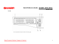
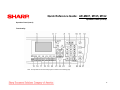
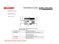
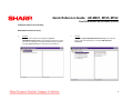
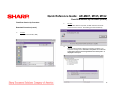
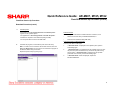
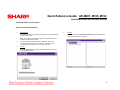
1
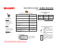
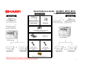
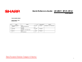
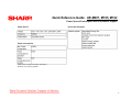
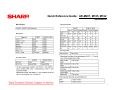
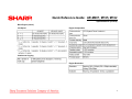
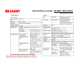
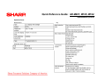
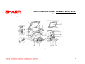
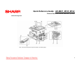
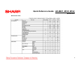
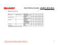
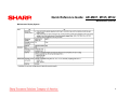
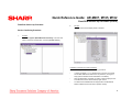
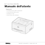
Quick Reference Guide: AR-M207, M165, M162
Description: Features & Options
Why the AR-M207, M165, M162
The AR-M162 and AR-M207 Digital IMAGERs™
Document Systems deliver advanced performance
for today’s small office—all in a value-driven,
multifunction copier. With a 500-sheet paper
capacity, (250 sheets on AR-M162), 100-sheet
bypass tray, standard 600 dpi host-based printing,
and auto duplexing (AR-M207), these compact
performers keep pace with even the most
demanding offices.
The AR-M162/M207 Digital IMAGERs™
The AR-M162 and AR-M207 Digital IMAGERs can
support full-color ledger-size PC scanning that
enables users to share or archive documents with
just a few keystrokes. With optional electronic
sorting and a speed-enhanced printing system, the
Sharp AR-M162 and AR-M207 IMAGERs can
easily help grow clients’ businesses.
Features
The Card Shot feature conveniently copies
both sides of an ID or insurance card onto a
single sheet of paper.
• 5-line LCD display
• Versatile paper handling
• Optional electronic sorting
• Offset stacking
The user-friendly control panel
makes the AR-M162/M207
IMAGERs simple to operate.
AR-M207
• AR-M162: 16-288 MB memory
• AR-M207: 32-304 MB memory
• 600 dpi host-based PC printing system
• Full color 600 x 600 dpi PC scanning
• Sharpdesk integrated Desktop Document
Management Software
• Button Manager Utility
• Standard IEEE 1284 parallel and USB 1.1
• Optional Super G3 Facsimile
AR-M162
Flexible Functionality and
Advanced Versatility
¾ Integrated Color PC Scanning
¾ Advanced Network Connectivity
¾ High-Quality Digital Copying
¾ Super Fast, Super G3 Faxing
Fax Reception Light flashes to
alert you when a new fax has
arrived.
1
Quick Reference Guide: AR-M207, M165, M162
Pre-Setup: Tools, MSDSs, & Admonitions
Equipment & Service Documentation
Description
Toolbox Basics
Part Number
AR-M207, M165, M162 Service Manual
SM-AR-M207
Code: 00ZARM207/A1E
AR-M207, M165, M162 Circuit Diagram
CD-AR-M2007
Code: 00ZARM207/C1/
AR-M207, M165, M162 Parts Guide
PG-AR-M207
Code: 00ZARM207/P1E
*AR-EB9 Service Manual
Digital Laser Copier Printer Option
Dual Function Board
SM-AR-EB9
Code: 00ZAREB9//A1E
AR-FX11 Service Manual
Fax Expansion Kit
SM-AR-FX11
Code: 00ZARFX11/A1E
*AR-NB3 Service Manual
Digital Copier/Printer/Multifunctional System Option
SM-AR-NB3
Code: 00ZARNB3//A1E
*AR-SP6N, RP6N Service Manual
Single Pass Feeder (SPF)
Reverse Single Pass Feeder (RSPF)
SM-AR-SP6N
Code: 00ZARSP6N/A1E
Product Code
Description
MSDS No.
AR-202MT
Toner Cartridge
(Black)
F-01211
AR-202MD
Developer
F-31211
* Download MSDSs at http://www.sharp-service.com
Mechanical
• Screwdriver, Phillips #2
Material Safety Data Sheets
(MSDSs)*
• Screwdriver, Flat #1
• Wrench, 1.5mm Hex head
• Feeler gauges
Electrical
• Voltmeter
• ESD wrist or ankle strap
• Approved surge suppressor
• 30x lighted viewing device
Miscellaneous
* Optional equipment
Electrical/Electronic Component
Admonitions
WARNING:
Electrical hazard.
Employ proper precautions when
working with high-voltage electrical
equipment.
!
• Clean, soft, lint-free cloths
• Alcohol
Laser Admonition
For your protection, do
not remove protective
covers or bypass safety
interlocks.
E
S
D
CAUTION: Improper handling of
electronic components can damage
the equipment.
Properly ground and wear an
electro-static device (ESD) on your
wrist or ankle when working with
electronic modules. Similarly, use
anti-static bags to protect electronic
components during storage or
shipping.
2
Quick Reference Guide: AR-M207, M165, M162
Configuration
Configuration
Configuration
AR-M162, M165
AR-M207
(Copier/Printer/Scanner Model)
(with the RSPF installed)
16 PPM Black & White
20 PPM Black & White
AR-M162/AR-M165
AR-M207
3
Quick Reference Guide: AR-M207, M165, M162
Configuration with Common Options
AR-NB3 Network Expansion
Kit with PCL Network Printing
and Network Scanning
(requires AR-EB9)
AR-SP6N
40-Sheet Single Pass Feeder
AR-FX11 Fax
Expansion Kit
AR-VR5 Document Cover
(Standard on AR-M162 only)
AR-RP6N 40-Sheet Reversing
Single Pass Feeder
AR-VR5 Document Cover
(Standard on AR-M162 only)
AR-EB9 Electronic Sorting Kit (includes
Card Shot and USB 2.0)
AR-TR4 Job
Separator Tray
AR-M207 IMAGER
AR-M167 IMAGER
OR
AR-D24 250-Sheet
Paper Feed Unit
AR-SM5 256 MB
Memory Expansion for
AR-EB9
AR-MM9 8 MB
Memory Expansion for
AR-FX11
AR-D25 250-Sheet x 2
Paper Feed Unit
AR-D24 250-Sheet
Paper Feed Unit
AR-D25 250-Sheet x 2
Paper Feed Unit
AR-PK1N Postscript PS3 Expansion Kit
4
Quick Reference Guide: AR-M207, M165, M162
Consumables
Consumable Items
Supply System Table
(USA/Canada)
5
Quick Reference Guide: AR-M207, M165, M162
Power Source/Consumption and Environment Support
Power Source
Environment Support
Power Consumption
*Must conform to energy saving laws, international
standards, and company regulations.
6
Quick Reference Guide: AR-M207, M165, M162
Specifications
Base Engine
Copy Speed (CPM)
Base Engine
First Copy Time
Print Performance
7
Quick Reference Guide: AR-M207, M165, M162
Specifications (cont’d)
Base Engine (cont’d)
Job Speed
Engine Composition
Continuous Copying
Engine Resolution
8
Quick Reference Guide: AR-M207, M165, M162
Specifications (cont’d)
Scanner Section
SPF/RSPF
Document Table
AB and inch can be switched to each other by SIM.
9
Quick Reference Guide: AR-M207, M165, M162
Specifications (cont’d)
Operation Panel
Display Device
Key
Characters used in LCD
10
Quick Reference Guide: AR-M207, M165, M162
Specifications (cont’d)
Operation Panel (cont’d)
Controller Board
Interface
11
Quick Reference Guide: AR-M207, M165, M162
External Views and Internal Structures
External Appearance
Note: The External Appearance Legend is located on the following page.
12
Quick Reference Guide: AR-M207, M165, M162
External Views and Internal Structures (cont’d)
External Appearance (cont’d)
Legend:
13
Quick Reference Guide: AR-M207, M165, M162
External Views and Internal Structures (cont’d)
Internal Arrangement
Note: The Internal Arrangement Legend is located on the following page.
14
Quick Reference Guide: AR-M207, M165, M162
External Views and Internal Structures (cont’d)
Internal Arrangement (cont’d)
Legend:
15
Note: The Internal Arrangement Legend
Quick Reference Guide: AR-M207, M165, M162
Operation Panel
For USA:
Note: The Operation Panel Legend is located on the following page.
16
Quick Reference Guide: AR-M207, M165, M162
Operation Panel (cont’d)
For USA (cont’d)
Legend:
17
Quick Reference Guide: AR-M207, M165, M162
Operation Panel (cont’d)
Operation Panel (cont’d)
Functionality
Note: The Operation Panel Functionality Legend is located on the following page.
18
Quick Reference Guide: AR-M207, M165, M162
Operation Panel (cont’d)
Operation Panel (cont’d)
Display (Base Screen)
Example: Copy Mode
19
Quick Reference Guide: AR-M207, M165, M162
Operation Panel (cont’d)
Operation Panel (cont’d)
Icons Appearing in the Special Function Icon Display
20
Quick Reference Guide: AR-M207, M165, M162
Simulaltions
Simulations
Entering the Simulation Mode
List of Simulations
Perform the following procedure to enter the simulation mode:
# key → * key → C key → * key →
Main code → Start key → Sub code → Start key
Canceling the Simulation Mode
To cancel the simulation mode, press the CLEAR ALL key.
Important: After canceling the simulation mode, be sure to
turn the power OFF/ON and check the operation.
When the interruption key is pressed, the process is interrupted
and the screen returns to the sub code entering display.
Note 1: If the machine is terminated by a jam error or paper
empty error during copying in the adjustment by the simulation,
recopying is required.
Note 2: The values in the simulation columns are not default
values but sample values.
21
Quick Reference Guide: AR-M207, M165, M162
Simulations (cont’d)
List of Simulations (cont’d)
22
Quick Reference Guide: AR-M207, M165, M162
Simulations (cont’d)
List of Simulations (cont’d)
23
Quick Reference Guide: AR-M207, M165, M162
Trouble Codes
Trouble Code List
24
Quick Reference Guide: AR-M207, M165, M162
Maintenance
Maintenance Table
25
Quick Reference Guide: AR-M207, M165, M162
Maintenance (cont’d)
Maintenance Table (cont’d)
26
Quick Reference Guide: AR-M207, M165, M162
Maintenance (cont’d)
Maintenance Display System
27
Quick Reference Guide: AR-M207, M165, M162
Key Operator Program
Key Operator Program
Custom Setting
28
Quick Reference Guide: AR-M207, M165, M162
Key Operator Program (cont’d)
Key Operator Program
Custom Setting (cont’d)
29
Quick Reference Guide: AR-M207, M165, M162
Flash ROM Version Up Procedure
Flash Rom Version Up Procedure
3.
Check that the following display is shown. Select “Install from a list or
the specific location” and press the [Next] button.
Preparation
USB Joint Maintenance Program Installation
The driver is installed by plug and play.
Installation Procedure on Windows XP
1.
Machine side:
Executable by performing the Service Simulation No. 49-01 (Flash ROM
program-writing mode).
Note: The words “Download Mode” appear on the operation panel to denote
the download mode status.
2.
Connect the machine and the PC with a USB cable. (Be sure to
connect the USB cable to the main unit side. Connection to the optional
dual function board cannot execute this function.)
30
Quick Reference Guide: AR-M207, M165, M162
Flash ROM Version Up Procedure
Flash Rom Version Up Procedure
Installation Procedure on Windows XP (cont’d)
4.
Select “Include this location in the search”. If the retrieval area does
not include the folder that includes the maintenance tool driver
(Mainte.inf), select the [Browse] button.
5.
Select the folder which includes the maintenance tool driver
(Mainte.inf), and press the [OK] button when the driver is included in
the “C:\Maintenance Tool\Driver2kxp” folder.
If the folder path is properly shown, press the [Next] button to go to
procedure 7.
31
Quick Reference Guide: AR-M207, M165, M162
Flash ROM Version Up Procedure (cont’d)
Flash Rom Version Up Procedure
Driver Installation Procedure (cont’d)
6.
Check that the path to the folder which includes the maintenance tool
driver (Mainte.inf) is shown, and press the [Next] button.
7.
Check that the following display is shown. Press the [Continue
Anyway] button.
32
Quick Reference Guide: AR-M207, M165, M162
Flash ROM Version Up Procedure (cont’d)
Flash Rom Version Up Procedure
Driver Installation Procedure (cont’d)
Installation Procedure on Windows 2000
8.
1.
When installation is completed, the following display is shown. Press
the [Finish] button.
Machine side:
Executable by performing the Service Simulation No. 49-01 (Flash ROM
program-writing mode).
Note: The words “Download Mode” appear on the operation panel to denote
the download mode status.
2.
Connect the machine and the PC with a USB cable. (Be sure to
connect the USB cable to the main unit side. Connection to the optional
dual function board cannot execute this function.)
3.
Check that the new hardware search Wizard is shown. Press the [Next]
button.
The installation procedure (on Windows XP) is completed
with the above operation.
33
Quick Reference Guide: AR-M207, M165, M162
Flash ROM Version Up Procedure (cont’d)
Flash Rom Version Up Procedure
5.
Select “Specify a location” and press the [Next] button.
6.
If the reference position is not the folder that includes the maintenance
tool driver (Mainte.inf) select the [Browse] button. If the reference
position is the folder which includes the maintenance tool driver, press
the [OK] button to go to procedure (9).
Installation Procedure on Windows 2000
4.
Select “Search for a suitable driver for my device” and then press the
[Next] button.
34
Quick Reference Guide: AR-M207, M165, M162
Flash ROM Version Up Procedure (cont’d)
Flash Rom Version Up Procedure
Installation Procedure on Windows 2000 (cont’d)
7.
Specify the folder that contains the maintenance tool driver (Mainte.inf),
and press the [Open] button.
8.
Check to confirm that the path to the folder which includes the
maintenance tool driver (Mainte.inf) is displayed, and press the [OK]
button.
(Supposing that the maintenance tool driver is included in the folder of
“C:\Maintenance Tool\Drivers\2kXp”.
35
Quick Reference Guide: AR-M207, M165, M162
Flash ROM Version Up Procedure (cont’d)
Flash Rom Version Up Procedure
Installation Procedure on Windows 2000 (cont’d)
9.
Press the [Next] button, and installation is started.
10.
When installation is completed, the following display is shown. Press
the [Finish] button.
11.
When the indication is displayed to reboot the PC, press the [Yes]
button and boot the PC.
The installation procedure (on Windows 2000) is completed
with the above operation.
36
Quick Reference Guide: AR-M207, M165, M162
Flash ROM Version Up Procedure (cont’d)
Flash Rom Version Up Procedure
Download Procedure
1.
Main Body Side:
Executable by performing the Service Simulation No. 49-01 (Flash ROM
program-writing mode).
3.
PC Side:
Boot “Maintenance.exe” and select [AR-M207/M162/M165 Series] on
the model selection menu.
Note: The words “Download Mode” appear on the operation panel to denote
the download mode status.
2.
Connect the machine and the PC with a USB cable. (Be sure to
connect the USB cable to the main unit side. Connection to the optional
dual function board cannot execute this function.)
(Sample display)
37
Quick Reference Guide: AR-M207, M165, M162
Flash ROM Version Up Procedure (cont’d)
Flash Rom Version Up Procedure
Download Procedure (cont’d)
4.
PC Side:
Check to confirm that “Simulation Command List” is displayed on the
integrated maintenance program.
5.
PC Side:
If “The copier is off.” is displayed on the lower left side after booting the
integrated maintenance program, select [File] and then [Reconnect] on
the menu bar.
38
Quick Reference Guide: AR-M207, M165, M162
Flash ROM Version Up Procedure (cont’d)
Flash Rom Version Up Procedure
Download Procedure (cont’d)
6.
PC Side:
Check to confirm that the tree is displayed on [Special
(MCU/IMC2/Panel/Facsimile)] of the integrated maintenance program.
If the tree is not displayed, check that the USB is properly connected
and select [Reconnect] again as in the previous procedure (5).
7.
PC Side:
Double-click [Special (MCU/IMC2/Panel/Facsimile)] on the main tree
items to extend the sub-tree items, and select [DWL Data Area
Download].
39
Quick Reference Guide: AR-M207, M165, M162
Flash ROM Version Up Procedure (cont’d)
Flash Rom Version Up Procedure
9.
Download Procedure (cont’d)
8.
PC Side:
When the DWL data file is specified, the DWL data file is transferred
from the PC to the machine. Downloading proceeds automatically.
PC Side:
Specify the download file (*.dwl).
10.
PC Side:
When the message below is displayed, download is completed. The
completion message reads: Download is completed. Do not turn the
copier power off until “Processing finished. Turn off the power.” is
displayed on the copier.
40
Quick Reference Guide: AR-M207, M165, M162
Flash ROM Version Up Procedure (cont’d)
Flash Rom Version Up Procedure
Download Procedure (cont’d)
11.
Main Body Side:
Wait until the words “Processing finished. Turn OFF the power.”
appears on the operation panel.
Failed Downloads
The appearance of “Processing finished. Turn OFF the power.”
indicates the completion of the download (writing to ROM).
•
Switch OFF the main body of AR-M207/M162/M165, or
•
Disconnect the download cable (USB cable)
Turn the power OFF and remove the USB cable.
The following actions will result in a failed download. Therefore ,do not:
Corrective Actions for Failed Downloads
12.
Terminate the program, and turn ON the power of the main body.
Note: To make a second connection with another machine, select the
[File] .and [Reconnect] in the menu bar on the maintenance program at
the time the USB is being reconnected.
Turn the power OFF and ON again.
1.
If “Download mode.” is displayed on the operation panel, perform
downloading again.
2.
If “Download mode.” is not displayed on the operation panel, turn OFF
the power and press and hold the 4 key and the CA key while turning
ON the power. If “Download mode.” is displayed on the operation
panel LED of the machine, perform downloading again.
3.
If “Download mode.” is still not displayed, replace the
MCU/Panel/IMC2/Fax.
Repeat the previous steps (7) through (12)
41
Quick Reference Guide: AR-M207, M165, M162
Flash ROM Version Up Procedure (cont’d)
Flash Rom Version Up Procedure
Version Confirming Procedure
1.
Machine Side:
Executable by performing the Service Simulation No. 49-01 (Flash ROM
program-writing mode).
4.
PC Side:
Check to confirm that “Simulation Command List” tree is displayed on
the integrated maintenance program.
Note: The words “Download Mode” appear on the operation panel to
denote the download mode status.
2.
Connect the machine and the PC with a USB cable. (Be sure to
connect the USB cable to the main unit side. Connection to the
optional dual function board cannot execute this function.
3.
PC Side:
Boot “Maintenance.exe” and select [AR-M207/M162/M165 Series] on
the model selection menu.
42
Quick Reference Guide: AR-M207, M165, M162
Flash ROM Version Up Procedure (cont’d)
Flash Rom Version Up Procedure
Version Confirming Procedure
5.
PC Side:
If “The Copier is Off.” is displayed on the left lower side after booting
the integrated maintenance program, select [File] and then [Reconnect]
on the menu bar.
6.
PC Side:
Check to confirm that the tree is displayed on [Special
(MCU/IMC2/Panel/Facsimile)] of the integrated maintenance program.
If the tree is not displayed, check that the USB is properly connected
and select [Reconnect] again in the previous procedure of (5).
43
Quick Reference Guide: AR-M207, M165, M162
Flash ROM Version Up Procedure (cont’d)
Flash Rom Version Up Procedure
8.
PC Side:
Check to confirm that the display below is indicated.
Version Confirming Procedure
7.
PC Side:
Double-click [Special (MCU/IMC2/Panel/Facsimile)] on the main tree
items to extend the sub-tree items, and select [Confirm version].
Verification Procedures for Version Confirming
Version confirming is completed with the following procedures:
•
In version confirming, “**.**.**” means that the connection is not made
with the MCU PWB or that download is not performed. (The figure in
Step (8) above indicates that the FAX PWB is not installed.)
•
When the download is completed, the version number is displayed such
as the MCU boot version and the MCU program version.
•
The CPM and the SD-RAM size are displayed when the MCU/Panel
PWB is installed and the boot section operates normally.
44