1
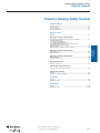
Presence Sensing Safety Devices
Presence Sensing Safety Devices
Selection Criteria
General
Table of Contents
POC Type 4 Safety Light Curtains
GuardShield™ Standard, Remote Teach, and Cascadable......................... 2-13
Standard GuardShield
Remote Teach GuardShield
Cascadable GuardShield System
GuardShield with Integrated Laser Alignment System
ArmorBlock Guard I/O Connectivity
GuardShield Safe 4 ...................................................................................... 2-27
GuardShield Micro 400, Micro 400 Cascadable .......................................... 2-33
POC Type 2 Safety Light Curtains
GuardShield Type 2 ...................................................................................... 2-42
GuardShield Safe 2 ...................................................................................... 2-50
PAC Type 4 Safety Light Curtains
2-Table of
Contents
Opto-electronics
Overview ......................................................................................................... 2-8
Principles
Selection Flowchart .........................................................................................2-2
Selection Tips ..................................................................................................2-3
Selection Navigator .........................................................................................2-4
Technology Overview.......................................................................................2-6
GuardShield PAC.......................................................................................... 2-56
GuardShield PAC Safe 4 .............................................................................. 2-64
Safety Light Curtain Interfaces
120V AC Power Supply and Safety Relay ................................................... 2-79
Safety Laser Scanner
Overview ....................................................................................................... 2-82
SafeZone™ Singlezone/Multizone ............................................................... 2-84
Safety Switches
Safety Single Beam
Area Access Control..................................................................................... 2-70
Safety Mats
Safety Edges
Power
Logic
Overview ..................................................................................................... 2-104
Safedge™ Profiles...................................................................................... 2-107
Operator
Interface
Overview ....................................................................................................... 2-90
MatGuard™ Mats ........................................................................................ 2-94
Visit our website: www.ab.com/catalogs
R
Publication S117-CA001A-EN-P
2-1
Presence Sensing Safety Devices
Selection Flowchart
General
Is the hazardous area
stationary or mobile?
Stationary
Mobile
Safety Edge
Stop
initiated by
contact?
Principles
Laser Scanner
Yes
No
Gate with
Safety Mats or
Laser Scanner
2-Selection
Criteria
How
often do you
need access to the
hazardous
area?
Are
there any
Yes
blind spots where
you can not see a person
in the hazardous
area?
Rarely
Frequently
No
Gate with Interlock
Switches
POC Light
ght Curtain
Safety Switches
Do
you need to
detect full or partial
body access?
Partiall
Full
Operator
Interface
Can a
light curtain or
mirrors be mounted
around the
area?
Yes
Are
there any
blind spots where
you can not see a person
in the hazardous
area?
No
Laser Scanner
or Safety Mats
Laser Scanner
No
Is the
shape of the
hazard square/
rectangular?
Yes
Yes
Laser Scanner
or Safety Mats
No
PAC Light Curtain
or Safety Mats
Logic
Power
Visit our website: www.ab.com/catalogs
2-2
Publication S117-CA001A-EN-P
R
Presence Sensing Safety Devices
Selection Tips
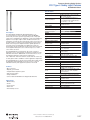
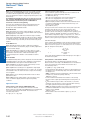
Is the hazardous area stationary or mobile?
A stationary hazard refers to a fixed machine or work cell where one or more mechanical hazards exist. A mobile hazard is generally a fixedrail linear transfer mechanism (e.g., a transfer cart or conveyor) or an Automatic Guided Vehicle (AGV). Use of a safety device on a mobile
hazard generally relates to collision avoidance with personnel or surrounding machinery.
General
Selection Tips
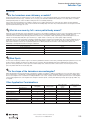
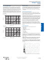
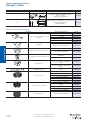
Partial-body access, on the other hand, is required for applications where an operator must regularly reach into a machine hazard as part of
the process at the point of operation (known as POC or Point of Operation Control). In the case of opto-electronic safety devices such as
light curtains and area scanners, full- or partial-body detection is directly related to the resolution of the safety device. Below is the
relationship of sensing field resolution to the type of detection:
Object to be Detected/Protected
Resolution
Finger (vertical field)
14 mm
Hand (vertical field)
30 mm
Limb (horizontal field for leg detection)
50 mm, 70 mm
Full Body (horizontal fields)
150 mm
Blind Spots
In some cases it may be possible for a person to enter the guarded area and be lost from view, potentially allowing the guard door to be shut
and the machine started by another person. Often used in conjunction with hard guarding and a gate outfitted with an interlock switch,
presence sensing safety devices such as pressure-sensitive safety mats, and laser scanners can be used to check for the presence of a
person anywhere within the enclosed safety area.
2-Selection
Criteria
Full-body access generally refers to the requirement for a person to be standing or walking in (or have access to) the hazardous area around
a machine that does not require frequent interaction between personnel and the hazard during regular operation; generally this is for
maintenance and troubleshooting. Full-body perimeter or area access control (PAC or AAC, respectively) is achieved through the use of a
vertical or horizontal safety field, either opto-electronic (i.e., a light curtain or scanner) or by contact (safety edges and mats).
Safety Switches
What do we mean by full- versus partial-body access?
Principles
In the instance that the hazard moves toward the operator (such as with powered doors) as opposed to the operator moving toward the
hazard, a pressure-sensitive safety edge can be mounted to the leading edge of the door. Any contact between the door and personnel will
stop the machine before injury can occur.
When the hazardous area to be monitored is a rectangle (or a shape consisting of contiguous rectangles), access to the area can be easily—
and cost-effectively—controlled with a standard safety mat. When the hazardous area is irregularly shaped, a custom mat is a viable option,
but not necessarily the most cost-effective or readily available. In such a case, a safety scanner is the best option because its scanning field
can be easily programmed to scan irregular areas and ignore obstacles (walls, columns) while detecting moving objects (people, AGVs, etc.)
as required.
Operator
Interface
Is the shape of the hazardous area rectangular?
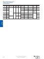
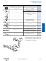
Other Application Considerations
Safety Mats
Safety Scanner
14 mm
Hand Detection
30 mm
Limb Detection
50/70 mm
Full Body Detection
Perimeter Access
Control
Uneven Floor
Corrosive Chemicals
Steam, Dust Environment
Reflections, Bright Ambient Light
Horizontally Mounted
IP67/IP69K Enclosure
IP67 Enclosure
Power
High-Pressure Washdowns
30 mm
Logic
Finger Detection
Partial Body Detection
Point of Operation
Control
Visit our website: www.ab.com/catalogs
R
Publication S117-CA001A-EN-P
2-3
Presence Sensing Safety Devices
Safety Light Curtains
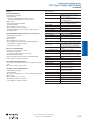
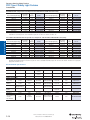
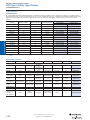
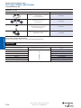
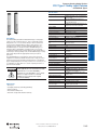
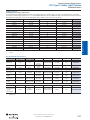
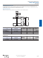
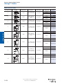
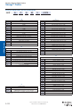
Selection Navigator
GuardShield
Light
Curtain
General
Standard
Safe 4
Profile
Size
[mm]
Type According to
IEC 61496
Finger
Hand
(14 mm) (30 mm)
40 x 50
30 x 40
Yes
Micro 400
15 x 20
PAC
40 x 50
Yes
Principles
2 and 3
beams
Type 2
30 x 40
NA
40 x 50
Type 2
Safe 2
30 x 40
Yes
Response Time
IP Rating
Integrated
Laser
Alignment
160…1760
14 mm…7 m
30 mm…16 m
20…30 ms
IP65 (IP67)
Optional/Yes
120…1920
14 mm…9 m
30 mm…18 m
14 mm: 11…90 ms
30 mm: 8…48 ms
IP65
Yes
150…1200
5m
14 mm: 15…42 ms
30 mm: 13…24 ms
Micro 400
IP54 (IP69K)
MSR4x
IP20
NA
2 beams: 520
3 beams: 820
16 m
20 ms
2 beams: 600
3 beams: 840
5…30 m
2 beams: 11 ms
3 beams: 14 ms
160…1760
16 m
20 ms
NA
18 m
14 mm: 11…90 ms
30 mm: 8…48 ms
Yes
Protective
Height [mm]
NA
Type 4
NA
Safe 4 PAC
Full
Body
Range
NA
120…1920
Optional/Yes
Yes
IP65
2-Selection
Criteria
Safety Switches
Operator
Interface
Logic
Power
Visit our website: www.ab.com/catalogs
2-4
Publication S117-CA001A-EN-P
R
Presence Sensing Safety Devices
Safety Light Curtains
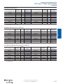
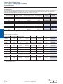
Selection Navigator
Cascadable
Muting
Configuration
Yes
Yes
Yes
1 PNP 0.5 A
max.
Yes
DIP Switch
NA
NA
NA
NA
Yes with
MSR42 or
MSR22LM
Yes with
MSR42
Yes with
MSR42
MSR41: 2 PNP
0.1 A max.
MSR42: 2 PNP
config.
Yes
Yes with
MSR42
MSR42 Wiring or
Software
Yes
1 PNP 0.5 A
max.
NA
NA
0…55°
(32…131°)
NA
-10…55°
(14…131°)
Yes
0…55°
(32…131°)
NA
-10…55°
(14…131°)
NA
1 PNP 0.5 A
max.
NA
NA
Yes with
MSR42 or
MSR22LM
GuardShield
Light Curtain
Standard
Safe 4
NA
PLe/SIL CL3
Micro 400
DIP Switch
PAC
NA
Safe 4 PAC
Factory
Type 2
Pld/SIL CL2
NA
Safe 2
Safety Switches
2-Selection
Criteria
0…55°
(32…131°)
Factory
Option
NA
PL/SIL CL
General
Aux. Output
Operator
Interface
Yes
EDM
Logic
Requires
MSR41 or
MSR42
-10…55°
(14…131°)
Blanking
Power
Yes
Beam
Coding
Principles
Operating
Integrated Temperature
Controller
[C (F)]
Visit our website: www.ab.com/catalogs
R
Publication S117-CA001A-EN-P
2-5
Presence Sensing Safety Devices
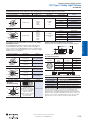
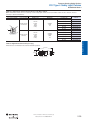
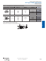
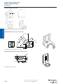
Technology Overview
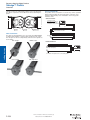
Safedge™ Pressure-Sensitive Safety Edges
Features/Benefits
General
Principles
Pressure-sensitive safety edges are flexible strips that can be mounted to the edge of a
moving part—such as a machine table or powered door—that poses a crushing or
shearing risk. Contact of the edge with an object or personnel switches off the machine
hazard. Safety edges are a cost-effective solution for constant safety monitoring in smaller
areas, especially those applications requiring physical flexibility and a tight turn radius.
Rated to Category 3, safety edges do not develop ‘dead spots’ like some other pressuresensitive safety offerings. They are also easy to install and maintain, and can withstand
high-pressure washdowns, making them suitable for a wide range of applications and
environments. Multiple profile sizes and the availability of custom edge systems also lend
to a high degree of application flexibility. It is important to note that Safedge requires a
dedicated safety relay for monitoring and control, which can be connected to other safety
systems.
Applications
Common Misapplications
Sliding doors
Garage doors
Pinch points
Submersible applications
Exposure to volatile chemicals (that can
damage the rubber profile)
Applications where physical contact can
injure personnel
2-Selection
Criteria
MatGuard™ Pressure-Sensitive Safety Mats
Features/Benefits
Safety Switches
Pressure-sensitive safety mats provide constant guarding and monitoring of a floor area
around a machine; 66 lbs. or more of pressure on the mat (e.g., an operator’s footstep)
causes the mat controller unit to switch off power to the hazard. Like safety edges,
MatGuard safety mats are easy to apply and maintain, can withstand high pressure
washdowns and are not susceptible to dead spots. An ideal solution for relatively small
areas, MatGuard products also offer a high degree of application flexibility, offering
reversible mats, direct micro quick connectivity to controllers, simple connection to
standard and DeviceNet Safety I/O blocks, custom system configurations, and quickdelivery standard sizes. However, mats can be damaged by dropped objects, such as tool
dies, and pose a potential trip hazard if trim is not used.
Applications
Common Misapplications
Work cells
Area detection
Uneven floors
Lack or improper use of uniting trim
Presence of volatile chemicals
Operator
Interface
SafeZone™ Safety Laser Scanners
Features/Benefits
Logic
The SafeZone safety laser scanners are opto-electronic devices that create a userconfigurable scanning field with one or more safety zones. If a person or object enters the
warning field, the SafeZone scanner switches a single output that can be used to initiate a
warning signal, such as an optical or acoustic alarm. If the inner safety field is breached,
the scanner switches two independent safety outputs initiating a machine stop signal to
halt dangerous machine motion. Offering warning fields up to 49 meters, the SafeZone is
easy to install—either horizontally or vertically—and requires no dedicated controller for
operation. Suited for Category 3, SIL2 PLd applications, the scanner is easily interfaced
with other safety systems and the easy-to-use configuration software allows
customization of the field shape.
Power
Applications
Common Misapplications
Work Cells
Robot Cells
Stationary or mobile application
Rotary and index tables
Moving automated vehicles (AGVs)
Infeed machinery
Overhead cranes
Oil, mist, dust, or steam environments
Outdoor applications
Extreme temperatures
Visit our website: www.ab.com/catalogs
2-6
Publication S117-CA001A-EN-P
R
Presence Sensing Safety Devices
Technology Overview
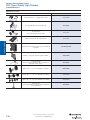
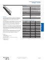
Point of Operation Control (POC) Light Curtains
Used on full revolution machinery
Mounted too close to hazard
Safety Switches
2-Selection
Criteria
Common Misapplications
GuardShield Micro 400
Perimeter Access Control (PAC) Light Curtains
Features/Benefits
PAC light curtains are an easy-to-install, Category 4 solution for full-body access
detection. Designed to create a safety perimeter around a machine that does not require
frequent interaction between personnel and the hazard during regular operation, PAC light
curtains provide large object pass-through sensing with detection ranges up to 30 meters.
PAC light curtains can be easily interfaced with other safety systems or used as
standalone units without a dedicated control unit/safety relay. However, it is important to
note that these light curtains do not detect people or objects once they have passed
through the light curtain.
Applications
Common Misapplications
Conveyor Systems with muting
Robot cells
Opto-electronic fence
Washdown with IP 67 tube
Used as POC device
Used on machine that does not stop until
completing a full revolution
Horizontal installation
Operator
Interface
GuardShield
Safe 4
Applications
Conveyors
Electronic fences
Forming operations
Robot Cells
Presses
Workstations
Washdown applications (use IP 67 tube
accessory)
Logic
GuardShield
Principles
POC light curtains are also suitable for use in washdown applications when used in
conjunction with the IP67 or IP69K light curtain enclosures.
General
Features/Benefits
POC light curtains are placed close to the hazard, at the point of operation where
personnel may frequently interact with the machine as part of a process. POC light
curtains are designed for partial-body detection—finger, hand, and arm detection—and
are offered in multiple resolutions and protective heights. An easy-to-install Category 4 SIL
3, PLe solution, these light curtains are easily connected to other safety systems, but
usually do not require a separate controller and can therefore be operated as standalone
units (i.e., without a safety relay). Since they are located at the machine’s point of
operation, POC light curtains eliminate the need for gates, allowing frequent and easy
access to the hazardous area, and can be used as an ergonomic workstation control that
increases safety while enhancing productivity. These light curtains can be mounted
vertically or horizontally. However, it is important to note that these light curtains do not
detect people or objects once they have passed through the light curtain.
GuardShield
PAC
Power
GuardShield
Safe 4 PAC
Visit our website: www.ab.com/catalogs
R
Publication S117-CA001A-EN-P
2-7
Presence Sensing Safety Devices
Safety Light Curtains
Overview
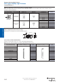
GuardShield™
3
Introduction
General
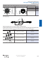
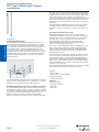
The Allen-Bradley Guardmaster GuardShield is offered as a Type 2
and a Type 4 POC safety light curtain as well as a Type 4 PAC
safety light curtain. The Type 4 POC GuardShield is offered in both
14 mm and 30 mm resolutions while the Type 2 is offered in 30 mm
resolution only. The GuardShield PAC is offered with multiple beam
configurations with varying beam spacings. All GuardShield family
safety light curtains meet the requirements of IEC/EN 61496.
1
Principles
POC safety light curtains are designed to detect the presence of an
opaque object of a minimum resolution. These devices are usually
positioned in front of the point of operation hazard, however, they
may also be used for perimeter guarding applications.
Receiver
PAC safety light curtains are typically used as opto-electronic
fences or as whole body detection devices to detect personnel or
large objects when they pass through the sensing field. These PAC
safety light curtains are typically positioned around an area or in
front of a process entry or exit area.
2-Opto-electronics
The Allen-Bradley Guardmaster GuardShield is a two-box safety
light curtain, consisting of a nonmatched transmitter and receiver
pair. Any GuardShield transmitter of the same family (POC, PAC)
and same resolution will work with any receiver of the same family
and resolution. The synchronization between transmitter and
receiver is achieved optically. The first beam adjacent to the receiver
LEDs is the synchronization channel. This synchronization beam
cannot be blocked in a fixed or floating blanking application.
2
4
The Allen-Bradley Guardmaster GuardShield Type 4 is a two-box
light curtain with DIP switch selectable operating modes.
Safety Switches
The GuardShield safety light curtain has two transistor type PNP
safety outputs, referred to as OSSDs (Output signal switching
devices). These outputs may be connected to a safety relay module
or directly to the primary control element of a machine if the EDM
connection within the GuardShield receiver is also connected and
configured.
The standard GuardShield receiver also has an auxiliary nonsafety
output which can be connected to a PLC for status of the OSSDs,
to a stack light for signaling or to control an in-feed motor, etc.
The standard GuardShield requires separate transmitter and receiver
cables. The transmitter cable utilizes a 4-pin micro quick-disconnect
(M12) connector and is offered in lengths from 2 meters to 30
meters. The receiver cable has an 8-pin micro quick-disconnect
(M12) connector and is also offered in lengths from 2 meters to 30
meters.
Operator
Interface
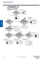
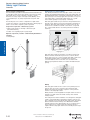
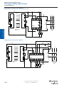
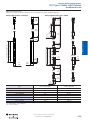
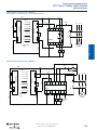
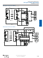
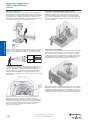
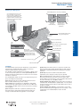
Typical System Configuration
Logic
Components required for a "Guard only" system:
1. Optic heads (operate on 24V DC—ordered as a pair
(transmitter/receiver)
2. Cable—two required per pair—specify transmitter cable and
receiver cable
3. Mounting brackets—included
4. Safety Relay Module—optional (Note: A Category 3 system may
be possible by connecting the GuardShield OSSDs directly to
two safety contactors and connecting and configuring the EDM
mode of operation in the GuardShield receiver.)
Interlock
Door Status
Switch
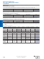
Mode
Activation
Button
Guard Only
Fixed
Blanking
2 Beam
Floating
Blanking
(14 mm only)
Unused
MPCE/EDM
1 Beam
Floating
Blanking
Beam
Coding
Receiver DIP Switch Functions or GuardShield Type 4 POC
Power
Visit our website: www.ab.com/catalogs
2-8
Publication S117-CA001A-EN-P
R
Presence Sensing Safety Devices
Safety Light Curtains
Overview
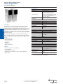
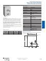
GuardShield Safe 4
The GuardShield Safe 4 is a Type 4 safety light curtain offered in
POC and PAC versions with basic ON/OFF functionality. The Safe 4
POC is offered in both 14 mm and 30 mm resolutions in protective
heights ranging from 120 mm up to 1920 mm in increments of 120
mm.
The GuardShield Safe 4 PAC (Perimeter Access) is offered with two
120 mm modules providing 500 mm spacing and with three 120 mm
modules providing 400 mm spacing. Both the two- and three-beam
Safe 4 PAC versions have an operating range from 5 meters up to
30 meters.
The GuardShield Micro 400 requires a dedicated controller, either an
MSR42 or MSR41. The MSR41 is a basic controller for simple
ON/OFF functionality and the MSR42, in addition to providing
operating functionality for the Micro 400, can be used as a multifunction safety module. This multi-functional safety module allows
the connection of additional safety light curtains, safety laser
scanner or a safety device with PNP type outputs as well as E-stops
or override switches. The MSR42 can have limited functionality
activated by wiring but requires configuration software for any
advanced functionality.
The Micro 400 transmitter and receiver are offered with eight-pin
M12 connectors at the end of 500 mm (19.8 in.) integrated cables.
The patchcords to connect the transmitter and receiver to the
controller are the same cat. no. and are offered in various lengths.
These patchcords are configured on one end with M12 connectors
that mate to the integrated pigtail connectors and RJ45 connectors
on the opposite end, that plug into the MSR41 or MSR42 controller.
The Micro 400 is also offered in cascadable configurations.
GuardShield Cascadable Micro 400 safety light curtains allow the
interconnection of multiple segments of the Micro 400 safety light
curtain with a common pair of safety outputs. This cascadable
configurability of the GuardShield Micro 400 reduces overall system
wiring and allows the GuardShield Micro 400 to be fitted into a
variety of applications where the safety distances for mounting the
light curtain may allow personnel to stand between the light
curtain’s sensing field and the hazard or where multiple-sided
guarding is required and the use of corner mirrors is not possible.
General
Operator
Interface
The GuardShield Safe 4 POC and Safe 4 PAC are economical Type
4 safety light curtains with ON/OFF functionality and an integrated
laser alignment system. The integrated laser alignment system
consists of a constantly powered Class 2 visible laser located on the
top of the transmitter and on the bottom of the receiver. The
constantly powered integrated laser alignment systems allows a low
level of laser light to be emitted. Simply touching a finger to the
laser beneath the finger symbol reflects the low level of laser light
back to a photo sensor which causes the laser light intensity to
increase for five minutes or until a finger covers the laser reflecting
the laser back to the photo sensor which signals a reduction of the
intensity of the emitted laser light. This system assures that both the
top and bottom of the Safe 4 pair are quickly and easily aligned or
realigned if a light curtain or corner mirror is inadvertently moved
during operation.
The compact housing size allows the GuardShield Micro 400 to be
mounted in areas where standard safety light curtains may not be
able to be mounted due to space constraints.
Principles
The receiver DIP-switches provide for configuration of all of the
GuardShield safety light curtain's modes of operation.
2-Opto-electronics
The transmitter DIP-switches provide for the configuration and
activation of Beam Coding and Machine Test Signal.
GuardShield Micro 400
The GuardShield Micro 400 is an economical three-box (transmitter,
receiver and controller) Type 4 safety light curtain offered in a small
profile (15 mm X 20 mm) housing. Designed for use in benign
industrial environments (IP54), this medium/light duty safety light
curtain system is targeted to the semi-conductor, microelectronic
and small assembly machine markets.
Safety Switches
The standard GuardShield safety light curtain has DIP-switches
located in both the transmitter and receiver endcaps. The DIPswitches are accessible through a hinged door that is secured to the
endcap with a security screw.
GuardShield Micro 400
GuardShield Safe 2
Micro 400 Cascading
Power
The GuardShield Safe 2 is a Type 2, SIL 2, PLd, safety light curtain
offered with a 30 mm resolution in protected heights ranging from
120 to 1920 mm in 120 mm increments. The GuardShield Safe 2 is
an economical, two-box safety light curtain with ON/OFF
functionality and an integrated laser alignment system. The
integrated laser alignment system consists of a Class 2 visible laser
located at the top of the transmitter and the bottom of the receiver.
Each laser has a target located opposite the laser on the transmitter
and receiver. This integrated laser alignment system facilitates
alignment at installation and during the course of usage if the Safe 2
pair is knocked out of alignment.
Micro 400 Cascaded
Visit our website: www.ab.com/catalogs
R
Logic
GuardShield
Safe 4
Publication S117-CA001A-EN-P
2-9
Presence Sensing Safety Devices
Safety Light Curtains
Overview
General
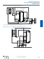
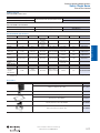
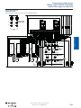
Typical System Configurations
Perimeter Access Control (PAC)
The Allen-Bradley Guardmaster GuardShield and GuardShield Safe
4 safety light curtains are two-box designs. This means the safety
light curtain does not need a separate controller to operate.
Therefore, the safety outputs of the light curtain (OSSDs) can be
connected directly to any safety relay that will accept two PNP
inputs.
Allen-Bradley Guardmaster PAC safety light curtains consist of two
families, the GuardShield PAC family and the Safe 4 PAC family. The
GuardShield PAC family is offered with multiple beams with various
beam spacings for short range applications (16 meters or less). The
Safe 4 PAC family is offered with multiple beams (2 or 3) with
various beam spacings for long range (5…30 meters).
The following are some common configurations of light curtain
systems. The numbers on the drawing indicate the ordering steps to
follow to ensure that a complete system is specified.
PAC safety light curtains are opto-electronic through-beam devices
typically used to detect personnel around hazardous equipment or
machinery. PAC safety light curtains are usually used as an optoelectronic fence and when used with corner mirrors, can provide
two- or three-sided detection around the perimeter of hazardous
machinery.
Components required for a “Guard only” system:
Principles
1. Optic heads (operate on 24V DC)—ordered as a pair
(transmitter/receiver)
2. Cables—two required per pair—specify length
Optional components (customer or Allen-Bradley Guardmaster
supplied):
3. Safety Relays
GuardShield
GuardShield
PAC
Transmitter
PAC
Receiver
2-Opto-electronics
1
Corner Mirror
Safety Switches
PAC safety light curtains are generally of resolutions that provide
detection of limbs and bodies of personnel, i.e., 50 mm, 70 mm,
90 mm and up. It is also common for PAC safety light curtains to be
offered with a limited number of infrared beams spaced at
consistent distances from one another, such as 3 beams with
400 mm spacing between beams, or 2 beams with 500 mm beam
spacing.
2
3
Operator
Interface
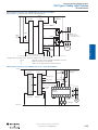
Muting
Logic
PAC safety light curtains are also used in conveyorized processes
and very often are used in conjunction with a muting module.
Muting is the temporary automatic suspension of the protective
function of the safety light curtain.
Muting modules can be integrated into the light curtain's receiver or
external to the light curtains. Rockwell currently offers external
muting modules.
Power
This muting function allows material to move through the safety light
curtain’s sensing field without stopping the machine, however, if a
person attempts to pass through the safety light curtain, they will be
detected and the machine will stop. The differentiation between
material and personnel is determined by the use of muting sensors.
These muting sensors create a particular switching sequence
together with the safety light curtain as the material passes through
the process.
Visit our website: www.ab.com/catalogs
2-10
Publication S117-CA001A-EN-P
R
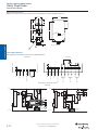
Presence Sensing Safety Devices
Safety Light Curtains
LC2
MS2
Muted LC1
MS1
Machine
Material
Conveyor
Muting Lamp
LC
Material
GuardShield Perimeter Access Control (PAC)
The following are some common configurations of light curtain
systems. The numbers on the drawing indicate the ordering steps to
follow to ensure that a complete system is specified.
MS2 MS1
Muted LC1
Machine
A requirement of muting in machine applications is for indication
that the muting function is activated. This is typically accomplished
by the use of a muting lamp. The various muting modules offered by
Rockwell Automation have an output for the connection of a muting
lamp.
The Allen-Bradley Guardmaster GuardShield PAC safety light curtain
system is a two-box design. This means the safety light curtain
does not need a separate controller to operate in a guard-only
mode with manual reset. Therefore, the safety outputs of the light
curtain (OSSDs) can be connected directly to any safety relay that
will accept PNP inputs.
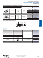
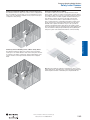
Figure 1: Two-sensor bi-directional muting
MS4 MS3
The muting sensors must be spaced appropriately from the safety
light curtain and each other in order to ensure that the sensors
cannot be interrupted by personnel, causing the activation of the
muting function.
Conveyor
Muting Lamp
Figure 2: Four-sensor uni-directional muting
Components required for a multiple-beam PAC system, see
Figure 3:
Optic heads (operate on 24V DC)—ordered as a pair
(transmitter/receiver) mounting brackets included
Cables—separate 4-pin transmitter and 8-pin receiver
Safety relay if EDM is not used
Corner mirrors (for multiple side protection)
Operator
Interface
LC
Principles
Conveyorized muting
Muting sensors are typically used in pairs and depending upon the
sensor configuration and muting module, allow either uni-directional
or bi-directional travel of material through the safety light curtain.
2-Opto-electronics
An interruption of the safety light curtain sensing field would cause
the machine or the hazardous motion to be turned off. The muting
cycle is completed when the material clears muting sensor 4.
Safety Switches
Four-sensor muting for this particular muting module in Figure 2
allows a single direction of travel. A particular sequence is also
required in this configuration; muting sensor 1 must be interrupted
first followed by muting sensor 2 and then the safety light curtain,
then muting sensor 3 and finally muting sensor 4. It is necessary
with this particular muting module to have the light curtain’s sensing
field interrupted within 3 seconds of muting sensor two being
interrupted. Also, the material must block muting sensor 3 and
muting sensor 4 before clearing muting sensors 1 and 2 or the
muting function is overridden and the safety light curtain would
become active causing a nuisance shutdown of the machine if the
material is within the light curtain sensing field.
General
Overview
MS2 MS1
Logic
Muting lamp
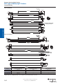
Figure 3: Two-sensor L-type with MSR42
LC
MS1
MS2
Power
Figure 4
Muting lamp
Figure 4: Two-sensor T-type with MSR42
Visit our website: www.ab.com/catalogs
R
Publication S117-CA001A-EN-P
2-11
Presence Sensing Safety Devices
Safety Light Curtains
Overview
General
Components Required for PAC with Muting, see Figure 4:
1. Optic heads (operate on 24V DC) with muting module—ordered
as a pair (transmitter/receiver)
2. It is also possible to use other Allen-Bradley Guardmaster muting
modules such as the MSR42 or the MSR22LM muting module
3. Power supply
4. Cables for light curtains
5. Muting indication
6. Sensors for muting
7. Sensor accessories
8. Sensor cordsets
Principles
Work
Piece
Power
Supply
2-Opto-electronics
Work
Piece
Perimeter Access Control Overview
Typical System Configurations
The Allen-Bradley Guardmaster Safe 4 PAC safety light curtain
system is a two box design. This means the safety light curtain does
not need a separate controller to operate in a guard-only mode.
Therefore, the safety outputs of the light curtain (OSSDs) can be
connected directly to any safety relay that will accept PNP inputs.
The following are some common configurations of light curtain
systems. The numbers on the drawing indicate the ordering steps to
follow to ensure that a complete system is specified.
Components required for a multiple-beam Safe 4 PAC, see
Figure 5:
1. Optic heads (operate on 24V DC)—ordered as a pair
(transmitter/receiver)
2. Cables—5-pin cables for transmitter and receiver
3. Safety relay
4. Power supply—120V AC to 24V DC
5. Mounting brackets—minimum of 4 per optic head pair
6. Corner mirror columns (for multiple side protection)
7. Mounting stand if required
1
Roller Work Path
5
MSR22LM or MSR42
Safety Switches
2
Work
Piece
Power
Supply
3
6
Work
Piece
Operator
Interface
4
Roller Work Path
MSR22LM
Figure 5
Logic
Power
Visit our website: www.ab.com/catalogs
2-12
Publication S117-CA001A-EN-P
R
Presence Sensing Safety Devices
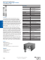
POC Type 4 Safety Light Curtains
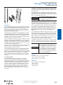
The GuardShield’s torsionally rigid, extruded aluminium,
polyurethane powder-coated housing, combined with an
environmental rating of IP65, allows the GuardShield to be used in
guarding applications across a broad range of industries.
The cascading GuardShield safety light curtains are ordered as pairs
(transmitter and receiver) and are shipped under one cat. no. After
selecting the appropriate pair of cat. nos. for a cascading
GuardShield system, select the interconnecting transmitter and
receiver patchcord cat. nos. to connect the GuardShield pairs. The
transmitter patchcord is a 4-pin M12 patchcord offered in lengths of
1/3 meter, 1 meter and 2 meters. The receiver patchcord is an 8-pin
M12 patchcord offered in lengths of 1/3 meter, 1 meter, and 2
meters.
Remote Teach GuardShield
The GuardShield Remote Teach system provides a remote means of
changing a fixed blanking configuration within the GuardShield
safety light curtain. This keyswitch box eliminates the need to open
the GuardShield receiver door and perform the Teach function.
If the end pair of a cascading system is a cascading pair of
GuardShield light curtains, it is necessary to attach a termination
adaptor to the top M12 connector located on the receiver. Be sure
to order all other required interfaces and accessories.
2-Opto-electronics
The complete cascading GuardShield system has the full
functionality of a standard GuardShield (beam coding, EDM,
start/restart interlock, fixed and floating blanking). There are a
couple of operating modes which can not be configured in the
middle and end segments (EDM and Start/Restart Interlock) and
must only be configured in the host (first) pair. The system will still
have these operating modes active if configured in the host or first
GuardShield pair. This host or first pair is the pair of cascading
GuardShield light curtains, which have the output cordsets
connected and wired to the safety relay, safety PLC or FSDs.
Configuring of the EDM operating mode in the end and middle
segments will cause the system to go to a lock-out condition after
the first interruption of the sensing field. Configuration of the
start/restart interlock operating mode in the end and middle
segments will cause the system to stay in a red condition awaiting
reset after the interruption of the sensing field.
Safety Switches
Modes of operation such as fixed and floating blanking, beam
coding, start/restart interlock, external device monitoring (EDM), and
machine test signal, are selected by DIP-switch settings. These DIPswitches are located beneath a security door, which are
conveniently located on both the transmitter and receiver end caps.
Operator
Interface
Standard GuardShield
The Allen-Bradley Guardmaster GuardShield safety light curtain is
an economical, fully featured, Type 4 safety light curtain in a
uniquely styled housing. GuardShield safety light curtains are
general-purpose presence sensing devices designed for use on
hazardous machinery providing point of operation, as well as
perimeter and access guarding. This self-contained, two-box, safety
light curtain has DIP-switch selectable operating modes and is
available in both 14 mm and 30 mm resolutions.
A cascadable GuardShield safety light curtain is a standard
GuardShield safety light curtain in 14 and 30 mm resolutions with
additional M12 connectors located on top of each safety light
curtain. The connector on the top of the safety light curtains allow
the interconnection of up to a total of three pair of GuardShield
safety light curtains with a common pair of OSSDs. The ability to
interconnect GuardShield pairs reduces overall system wiring and
simplifies the safety circuit resulting in a lower overall cost of a
multiple safety light curtain system. This product configurability also
allows a GuardShield safety light curtain system to protect multiple
sides of a machine or simply adds flexibility when positioning
GuardShield in various applications.
Logic
Cascadable GuardShield System
Description
Principles
General
GuardShield
The three-position key switch simulates the opening of the
GuardShield receiver door, teaching the GuardShield light curtain
the new fixed blanking area, closing the door and returning to the
run mode of operation.
Power
The IP65 rated key switch box is provided with a steel mounting
back plate to facilitate mounting of the box in proximity to the
GuardShield receiver. It is necessary to see the receiver LEDs when
performing the teach function.
Visit our website: www.ab.com/catalogs
R
Publication S117-CA001A-EN-P
2-13
Presence Sensing Safety Devices
POC Type 4 Safety Light Curtains
GuardShield
General
Patchcord
(2 meter max. length)
Principles
Last segment pair
can be cascading or
standard GuardShield pair
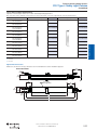
GuardShield with Integrated Laser Alignment System
Up to three GuardShield POC segments can be interconnected.
The upper and lower limit of the protective field is shown by
markings on the housings.
2-Opto-electronics
The width of the protective field is derived from the length of the
light path between transmitter and receiver and must not exceed the
maximum rated width of the protective field: 7 m for 14 mm (22.9 ft
for 0.55 in.), 18 m for 30 mm (59.0 ft for 1.18 in.).
Safety Switches
A maximum of three GuardShield light curtains can be
interconnected with a common pair of OSSDs. The maximum
number of beams allowed in a cascading system is 528 beams,
which equates to three 1760 mm cascading GuardShields in 14 mm
resolution. The individual segments can have mixed resolutions,
e.g., 14 mm and 30 mm as long as the pairs have the same
protective heights and resolutions.
Cascading segments are offered in protective heights from
320…1760 mm in both 14 mm and 30 mm resolutions. Cascading
segments of 160 mm are not offered, however; a 160 mm
GuardShield can be used as the last segment in a cascading
system.
The response time of a cascading GuardShield system is the
longest response time of any pair in the cascading system. For
example, if the response time of each pair in the cascading system
is 20 ms, then the cascading system's response time is 20 ms.
Operator
Interface
Cascading segments can be used as standalone light curtain pairs
or can have up to three segments interconnected. These cascading
segments all function as independent light curtains.
IMPORTANT
Logic
When cascading segments are used as
standalone pairs or as the last segment in a
cascading system, it is necessary to use a
termination plug on the top connector of
the GuardShield cascading receiver. It is
also possible to use a standard
GuardShield Type 4 POC pair as the last
segment in a cascading system.
The GuardShield POC and GuardShield POC cascadable light
curtains are offered with an integrated laser alignment system
consisting of a Class 1, eye safe, constantly powered laser located
in the top of the GuardShield transmitter and at the bottom of the
GuardShield receiver. There are targets located across from each
laser that help facilitate alignment of the light curtain when the laser
is emitting visible light.
Each laser emits a low level of visible light. Simply placing a finger
or opaque object in front of the laser reflects the laser light back to
a photo sensor. This photo sensor causes the laser to switch state
from a barely visible low level of emission to a higher level of
emission of visible light. Interrupting the visible light below the finger
symbol will cause the laser to change state back to a low level of
light emission. The visible light will also change to a low level after
five minutes.
The Integrated Laser Alignment system also quickly helps with the
re-alignment of pairs when units are knocked out of alignment
during the course of the work process or when corner mirrors are
used.
The GuardShield and Cascadable GuardShield are offered in 14 and
30 mm resolutions in protective heights from 320 to 1600 mm. The
160 and 1760 mm protective heights are not offered with the
integrated laser alignment systems.
ArmorBlock Guard I/O Connectivity
The GuardShield POC and GuardShield Cascadable light curtains
are also offered with the Class 1, eye safe, integrated laser
alignment system and connectivity to ArmorBlock Guard I/O. The
receiver of these light curtains has a five-pin M12 quick-disconnect
connector wired to connect to the 1732DS ArmorBlock I/O module,
allowing the GuardShield’s OSSDs to operate over a DeviceNet Safe
network.
This version of the GuardShield has limited configurability, i.e., only
beam coding, fixed and floating blanking can be configured by
setting the appropriate DIP switches and performing the teach
function. EDM, Start/Restart interlock, and the auxiliary output are
not available in these models.
You can use the ArmorBlock Guard I/O with any safety controller
that communicates on DeviceNet using CIP Safety for the control
and monitoring of safety circuits. ArmorBlock Guard I/O detects
circuit failures at each I/O point while providing detailed diagnostics
directly to the controller. With CIP Safety, you can easily integrate
safety and standard control systems by using safety and standard
messages on the same wire.
The 1732DS ArmorBlock Guard I/O family consists of 24V DC digital
I/O modules that communicate on DeviceNet networks.
Power
Visit our website: www.ab.com/catalogs
2-14
Publication S117-CA001A-EN-P
R
Presence Sensing Safety Devices
POC Type 4 Safety Light Curtains
Features
Specifications
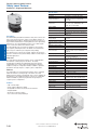
Standard GuardShield
Safety Ratings
Standards
IEC/EN 61496 Parts 1 & 2, UL 61496
Parts 1 & 2, UL 1998
Safety Classification
Type 4 per IEC/EN61496. Category 4
device per EN 954-1, SIL 3 per IEC 61508,
PLe per EN/ISO 13849
Certifications
cULus, UL 61496, UL 1998, TÜV, and CE
Marked for all applicable directives
Power Supply
0.4 A max (no load)
Outputs
Standard GuardShield with Integrated Laser Alignment
Safety Outputs
2 OSSD, 0.5 A, short-circuit protected
Fixed blanking—teachable
Floating blanking
Beam coding
M12 quick-disconnect connectors
Ease of alignment at installation with visible laser alignment
320…1600 mm in 160 mm increments
14 and 30 mm resolutions
Non-Safety Outputs
Auxiliary output, 0.5 A max.
Output Voltage, Min.
(Uv) - 2V
Switching Current @ Voltage,
Min.
500 mA @ 24V DC
Remote Teach GuardShield
Three-position momentary key switch
IP65 rated key switch box
Y connector for quick-disconnect connections
Standard GuardShield cables
Allows quick and efficient reteaching of fixed blanked areas
160 to 1760 mm in 160 mm increments
Operating Characteristics
Response Time
14 mm; 160 mm…1440 mm 20 ms, 1600
mm and 1760 mm, 25 ms. 30 mm; 20 ms.
Add 10 ms when beam coding activated.
Status Indicators
ON State, OFF State, Blanking, Alignment,
Interlock
Protected Height [mm (in.)]
See Product Selection tables.
Resolution [mm (in.)]
14 (0.55) or 30 (1.18)
Scanning Range/Resolution
0.3…7 m / 14 mm (0.98…22.9 ft / 0.55 in.)
0.3…16 m / 30 mm (0.98…52 ft / 1.18 in.)
Synchronization
Optical, first beam adjacent to LEDs.
Wavelength
870 nm
Environmental
Cascadable GuardShield System
Enclosure Type Rating
IP65
Easy to interconnect light curtains up to three 1760 mm segment
pairs
No increase in system response time
Relative Humidity
15…95% (noncondensing)
ArmorBlock Guard I/O GuardShield
-10…55° (14…131°)
Vibration
IEC60068-2-6: Frequency 10…55 Hz;
Amplitude: 0.35 mm (0.01 in.)
Shock
IEC60068-2-29: Acceleration 10 g, pulse
duration 16 ms 10…55 Hz
Physical Characteristics
Mounting
End-cap brackets supplied
Weight
Varies by protective height
Housing Cross Section
40 mm x 50 mm (1.57 in. x 1.96 in.)
Connection Type
Transmitter: 4-pin M12 micro QD; Receiver:
8-pin M12 micro QD
Cable Length
30 m (100 ft) max.
Power
Logic
Fixed blanking—teachable
Floating blanking
Up to three cascading pairs can connect to ArmorBlock Guard I/O
Beam coding
M12 quick-disconnect connectors
DeviceNet safe network connectivity
320…1600 mm in 160 mm increments
Operating Temperature [C (F)]
2-Opto-electronics
0.05 Vss
Power Consumption
Principles
24V DC ±20%
Maximum Residual Ripple
Safety Switches
Input Power, Max.
Operator
Interface
Fixed blanking—teachable
Floating blanking
− One-beam floating blanking on 30 mm resolution
− Two-beam floating blanking on 14 mm resolution
Beam coding
External Device Monitoring (EDM)
Start/restart interlock
M12 quick-disconnect connectors
160 to 1760 mm in 160 mm increments
Standard GuardShield can be used as last segment pair in a
cascading system
General
GuardShield
Visit our website: www.ab.com/catalogs
R
Publication S117-CA001A-EN-P
2-15
Presence Sensing Safety Devices
POC Type 4 Safety Light Curtains
GuardShield
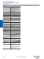
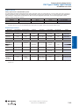
Product Selection
Standard System
General
The Allen-Bradley Guardmaster GuardShield safety light curtains are ordered as pairs—transmitter and receiver—and shipped under one cat.
no. After selecting the appropriate light curtain pair, ensure that required interfaces and accessories are ordered.
Protected Height [mm (in.)]
Resolution
[mm (in.)]
Number
of
Beams
Cat. No.
160 (6.3)
14 (0.55)
16
440L-P4J0160YD
Protected Height [mm (in.)]
Resolution
[mm (in.)]
Number
of
Beams
Cat. No.
160 (6.3)
30 (1.18)
8
440L-P4K0160YD
Principles
320 (12.6)
14 (0.55)
32
440L-P4J0320YD
320 (12.6)
30 (1.18)
16
440L-P4K0320YD
480 (18.9)
14 (0.55)
48
440L-P4J0480YD
480 (18.9)
30 (1.18)
24
440L-P4K0480YD
640 (25.2)
14 (0.55)
64
440L-P4J0640YD
640 (25.2)
30 (1.18)
32
440L-P4K0640YD
800 (31.5)
14 (0.55)
80
440L-P4J0800YD
800 (31.5)
30 (1.18)
40
440L-P4K0800YD
960 (37.8)
14 (0.55)
96
440L-P4J0960YD
960 (37.8)
30 (1.18)
48
440L-P4K0960YD
1120 (44.1)
14 (0.55)
112
440L-P4J1120YD
1120 (44.1)
30 (1.18)
56
440L-P4K1120YD
1280 (50.4)
14 (0.55)
128
440L-P4J1280YD
1280 (50.4)
30 (1.18)
64
440L-P4K1280YD
1440 (56.7)
14 (0.55)
144
440L-P4J1440YD
1440 (56.7)
30 (1.18)
72
440L-P4K1440YD
1600 (63.0)
14 (0.55)
160
440L-P4J1600YD
1600 (63.0)
30 (1.18)
80
440L-P4K1600YD
1760 (69.1)
14 (0.55)
176
440L-P4J1760YD
1760 (69.1)
30 (1.18)
88
440L-P4K1760YD
2-Opto-electronics
Note: The GuardShield transmitter requires a 4-pin cable and the receiver requires an 8-pin cable.
Note: To select just a transmitter or receiver, replace the "P" in the above cat. nos. with a "T" for transmitter and an "R" for receiver.
Remote Teach System
The Allen-Bradley Guardmaster GuardShield remote teach system is ordered as a system. The system consists of a standard GuardShield
transmitter in either 14 mm or 30 mm resolutions with mounting hardware, a GuardShield receiver with a 10 inch Y-connector cable, a metal
key switch box, and a 4-pin 2 meter patchcord which connects between the key switch box and the Y-connector.
Safety Switches
Protected Height [mm (in.)]
Resolution
[mm (in.)]
Number
of
Beams
Operator
Interface
Protected Height [mm (in.)]
Resolution
[mm (in.)]
Number
of
Beams
Cat. No.
160 (6.3)
14 (0.55)
16
440L-S4J0160YR
Cat. No.
160 (6.3)
30 (1.18)
8
440L-S4K0160YR
320 (12.6)
14 (0.55)
32
480 (18.9)
14 (0.55)
48
440L-S4J0320YR
320 (12.6)
30 (1.18)
16
440L-S4K0320YR
440L-S4J0480YR
480 (18.9)
30 (1.18)
24
640 (25.2)
14 (0.55)
440L-S4K0480YR
64
440L-S4J0640YR
640 (25.2)
30 (1.18)
32
800 (31.5)
440L-S4K0640YR
14 (0.55)
80
440L-S4J0800YR
800 (31.5)
30 (1.18)
40
440L-S4K0800YR
960 (37.8)
14 (0.55)
96
440L-S4J0960YR
960 (37.8)
30 (1.18)
48
440L-S4K0960YR
1120 (44.1)
14 (0.55)
112
440L-S4J1120YR
1120 (44.1)
30 (1.18)
56
440L-S4K1120YR
1280 (50.4)
14 (0.55)
128
440L-S4J1280YR
1280 (50.4)
30 (1.18)
64
440L-S4K1280YR
1440 (56.7)
14 (0.55)
144
440L-S4J1440YR
1440 (56.7)
30 (1.18)
72
440L-S4K1440YR
1600 (63.0)
14 (0.55)
160
440L-S4J1600YR
1600 (63.0)
30 (1.18)
80
440L-S4K1600YR
1760 (69.1)
14 (0.55)
176
440L-S4J1760YR
1760 (69.1)
30 (1.18)
88
440L-S4K1760YR
DC Micro Style Quick-Disconnect Patchcord, 4-Pin1
889D-F4ACDM-2
Remote Teach Keyswitch Box Assembly1
440L-M8600
Note: The GuardShield transmitter requires a 4-pin cable and the receiver requires an 8-pin cable.
Note: The GuardShield remote teach system light curtains can be ordered as pairs by replacing the "S" in the cat. no. a with "P."
1 Included with each system cat. no.; can be ordered as a replacement part.
Logic
Power
Visit our website: www.ab.com/catalogs
2-16
Publication S117-CA001A-EN-P
R
Presence Sensing Safety Devices
POC Type 4 Safety Light Curtains
GuardShield
Number
of
Beams
Protected Height [mm (in.)]
Resolution
[mm (in.)]
Number
of
Beams
Cat. No.
320 (12.6)
14 (0.55)
32
440L-C4J0320YD
Cat. No.
320 (12.6)
30 (1.18)
16
440L-C4K0320YD
480 (18.9)
14 (0.55)
48
640 (25.2)
14 (0.55)
64
440L-C4J0480YD
480 (18.9)
30 (1.18)
24
440L-C4K0480YD
440L-C4J0640YD
640 (25.2)
30 (1.18)
32
800 (31.5)
14 (0.55)
440L-C4K0640YD
80
440L-C4J0800YD
800 (31.5)
30 (1.18)
40
960 (37.8)
440L-C4K0800YD
14 (0.55)
96
440L-C4J0960YD
960 (37.8)
30 (1.18)
48
440L-C4K0960YD
1120 (44.1)
14 (0.55)
112
440L-C4J1120YD
1120 (44.1)
30 (1.18)
56
440L-C4K1120YD
1280 (50.4)
14 (0.55)
128
440L-C4J1280YD
1280 (50.4)
30 (1.18)
64
440L-C4K1280YD
1440 (56.7)
14 (0.55)
144
440L-C4J1440YD
1440 (56.7)
30 (1.18)
72
440L-C4K1440YD
1660 (63.0)
14 (0.55)
160
440L-C4J1600YD
1600 (63.0)
30 (1.18)
80
440L-C4K1600YD
1760 (69.3)
14 (0.55)
176
440L-C4J1760YD
1760 (69.3)
30 (1.18)
88
440L-C4K1760YD
Note: Cascadable systems are sold in pairs represented by the "C" in the cat. no. To order the cascadable transmitter or receiver, replace the "C" with a "G" for
the transmitter or "F" for the receiver.
Principles
Protected Height [mm (in.)]
Resolution
[mm (in.)]
General
Cascadable Standard System
Protected Height [mm (in.)]
Resolution
[mm (in.)]
Number
of
Beams
Cat. No.
320 (12.6)
14 (0.55)
32
440L-P4JL0320YD
Cat. No.
320 (12.6)
30 (1.18)
16
440L-P4KL0320YD
480 (18.9)
14 (0.55)
48
640 (25.2)
14 (0.55)
64
440L-P4JL0480YD
480 (18.9)
30 (1.18)
24
440L-P4KL0480YD
440L-P4JL0640YD
640 (25.2)
30 (1.18)
32
800 (31.5)
14 (0.55)
440L-P4KL0640YD
80
440L-P4JL0800YD
800 (31.5)
30 (1.18)
40
960 (37.8)
440L-P4KL0800YD
14 (0.55)
96
440L-P4JL0960YD
960 (37.8)
30 (1.18)
48
440L-P4KL0960YD
1120 (44.1)
14 (0.55)
112
440L-P4JL1120YD
1120 (44.1)
30 (1.18)
56
440L-P4KL1120YD
1280 (50.4)
14 (0.55)
128
440L-P4JL1280YD
1280 (50.4)
30 (1.18)
64
440L-P4KL1280YD
1440 (56.7)
14 (0.55)
144
440L-P4JL1440YD
1440 (56.7)
30 (1.18)
72
440L-P4KL1440YD
1600 (63.0)
14 (0.55)
160
440L-P4JL1600YD
1600 (63.0)
30 (1.18)
80
440L-P4KL1600YD
Note: GuardShields are sold in pairs. To select a transmitter or receiver, replace the "P" in the cat. no. with a "T" for transmitter and an "R" for receiver.
Cascadable GuardShield with Integrated Laser Alignment
Protected Height [mm (in.)]
Resolution
[mm (in.)]
Number
of
Beams
Protected Height [mm (in.)]
Resolution
[mm (in.)]
Number
of
Beams
Cat. No.
320 (12.6)
14 (0.55)
32
440L-C4JL0320YD
Cat. No.
320 (12.6)
30 (1.18)
16
440L-C4KL0320YD
480 (18.9)
14 (0.55)
48
640 (25.2)
14 (0.55)
64
440L-C4JL0480YD
480 (18.9)
30 (1.18)
24
440L-C4KL0480YD
440L-C4JL0640YD
640 (25.2)
30 (1.18)
32
800 (31.5)
14 (0.55)
440L-C4KL0640YD
80
440L-C4JL0800YD
800 (31.5)
30 (1.18)
40
960 (37.8)
440L-C4KL0800YD
14 (0.55)
96
440L-C4JL0960YD
960 (37.8)
30 (1.18)
48
440L-C4KL0960YD
1120 (44.1)
14 (0.55)
112
440L-C4JL1120YD
1120 (44.1)
30 (1.18)
56
440L-C4KL1120YD
1280 (50.4)
14 (0.55)
128
440L-C4JL1280YD
1280 (50.4)
30 (1.18)
64
440L-C4KL1280YD
1440 (56.7)
14 (0.55)
144
440L-C4JL1440YD
1440 (56.7)
30 (1.18)
72
440L-C4KL1440YD
1600 (63.0)
14 (0.55)
160
440L-C4JL1600YD
1600 (63.0)
30 (1.18)
80
440L-C4KL1600YD
Safety Switches
Number
of
Beams
Operator
Interface
Protected Height [mm (in.)]
Resolution
[mm (in.)]
2-Opto-electronics
GuardShield with Integrated Laser Alignment
Power
Logic
Note: Cascadable GuardShields are sold in pairs. To select a transmitter or receiver, replace the "C" with a "G" for cascadable transmitter and an "F" for a
cascadable receiver.
Visit our website: www.ab.com/catalogs
R
Publication S117-CA001A-EN-P
2-17
Presence Sensing Safety Devices
POC Type 4 Safety Light Curtains
GuardShield
GuardShield with Integrated Laser Alignment and ArmorBlock Guard I/O Connectivity
General
Protected Height [mm (in.)]
Resolution
[mm (in.)]
Number
of
Beams
Principles
Protected Height [mm (in.)]
Resolution
[mm (in.)]
Number
of
Beams
Cat. No.
320 (12.6)
14 (0.55)
32
440L-P4JL0320YA
Cat. No.
320 (12.6)
30 (1.18)
16
440L-P4KL0320YA
480 (18.9)
14 (0.55)
48
640 (25.2)
14 (0.55)
64
440L-P4JL0480YA
480 (18.9)
30 (1.18)
24
440L-P4KL0480YA
440L-P4JL0640YA
640 (25.2)
30 (1.18)
32
800 (31.5)
14 (0.55)
440L-P4KL0640YA
80
440L-P4JL0800YA
800 (31.5)
30 (1.18)
40
960 (37.8)
440L-P4KL0800YA
14 (0.55)
96
440L-P4JL0960YA
960 (37.8)
30 (1.18)
48
440L-P4KL0960YA
1120 (44.1)
14 (0.55)
112
440L-P4JL1120YA
1120 (44.1)
30 (1.18)
56
440L-P4KL1120YA
1280 (50.4)
14 (0.55)
128
440L-P4JL1280YA
1280 (50.4)
30 (1.18)
64
440L-P4KL1280YA
1440 (56.7)
14 (0.55)
144
440L-P4JL1440YA
1440 (56.7)
30 (1.18)
72
440L-P4KL1440YA
1600 (63.0)
14 (0.55)
160
440L-P4JL1600YA
1600 (63.0)
30 (1.18)
80
440L-P4KL1600YA
Note: GuardShields are sold in pairs. To select a transmitter or receiver, replace the "P" in the cat. no. with an "R" for a receiver. The GuardShield standard
transmitter is used in the pair. To order a transmitter, replace the "P" with a "T" and the "A" with a "D."
Cascadable GuardShield with Integrated Laser Alignment and ArmorBlock Guard I/O Connectivity
2-Opto-electronics
Protected Height [mm (in.)]
Resolution
[mm (in.)]
Number
of
Beams
Cat. No.
320 (12.6)
14 (0.55)
32
440L-C4JL0320YA
Protected Height [mm (in.)]
Resolution
[mm (in.)]
Number
of
Beams
Cat. No.
320 (12.6)
30 (1.18)
16
440L-C4KL0320YA
Safety Switches
480 (18.9)
14 (0.55)
48
440L-C4JL0480YA
480 (18.9)
30 (1.18)
24
440L-P4KL0480YA
640 (25.2)
14 (0.55)
64
440L-C4JL0640YA
640 (25.2)
30 (1.18)
32
440L-C4KL0640YA
800 (31.5)
14 (0.55)
80
440L-C4JL0800YA
800 (31.5)
30 (1.18)
40
440L-C4KL0800YA
960 (37.8)
14 (0.55)
96
440L-C4JL0960YA
960 (37.8)
30 (1.18)
48
440L-C4KL0960YA
1120 (44.1)
14 (0.55)
112
440L-C4JL1120YA
1120 (44.1)
30 (1.18)
56
440L-C4KL1120YA
1280 (50.4)
14 (0.55)
128
440L-C4JL1280YA
1280 (50.4)
30 (1.18)
64
440L-C4KL1280YA
1440 (56.7)
14 (0.55)
144
440L-C4JL1440YA
1440 (56.7)
30 (1.18)
72
440L-C4KL1440YA
1600 (63.0)
14 (0.55)
160
440L-C4JL1600YA
1600 (63.0)
30 (1.18)
80
440L-C4KL1600YA
Note: Cascadable GuardShields are sold in pairs. To select a transmitter or receiver replace the "C" with an "F" for a cascadable receiver. The cascadable
GuardShield standard transmitter is used in these pairs. To order a cascadable transmitter, replace the "C" with a "G" and the "A" with a "D" to specify the
appropriate transmitter cat. no.
Recommended Logic Interfaces
Description
Safety Outputs
Auxiliary Outputs
Terminals
Reset Type
Power Supply
Cat. Page No.
Cat. No.
Single-Function Safety Relays for 2 N.C. Contact Switch
Operator
Interface
Logic
MSR127RP
3 N.O.
1 N.C.
Removable
(Screw)
Monitored Manual
24V AC/DC
5-26
440R-N23135
MSR127TP
3 N.O.
1 N.C.
Removable
(Screw)
Auto./Manual
24V AC/DC
5-26
440R-N23132
MSR126
2 N.O.
None
Fixed
Auto./Manual
24V AC/DC
5-24
440R-N23117
MSR210P Base
2 N.C. only
2 N.O.
1 N.C. and 2 PNP
Solid State
Removable
Auto./Manual or
Monitored Manual
24V DC from the
base unit
5-82
440R-H23176
MSR211
2 N.O.
1 N.C.
Removable
Auto./Manual or
Monitored Manual
24V DC from the
base unit
5-84
440R-H23177
MSR310P Base
MSR300 Series
Output Modules
3 PNP Solid State
Removable
Auto./Manual
Monitored Manual
24V DC
5-102
440R-W23219
MSR320P Input
Module
—
2 PNP Solid State
Removable
—
24V DC from the
base unit
5-106
440R-W23218
MSR22LM
2 N.O.
1 N.C.
Removable
Auto./Manual
24V DC
5-48
440R-P23071
MSR42 (requires
optical interface to
configure
445L-AF6150
2 PNP
2 PNP,
configurable
Removable
Auto./manual or
manual monitored
24V DC
5-52
440R-P226AGS-NNR
Modular Safety Relays
Muting Modules
Power
Visit our website: www.ab.com/catalogs
2-18
Publication S117-CA001A-EN-P
R
Presence Sensing Safety Devices
POC Type 4 Safety Light Curtains
GuardShield
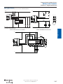
Standard and Remote Teach Cordsets—Two Required (one for transmitter and one for receiver)
2 (6.56)
889D-F4AC-2
2
1
3
Straight Female
1 Brown
2 White
3 Blue
4 Black
22 AWG
300V
4A
4
5 (16.4)
889D-F4AC-5
10 (32.8)
889D-F4AC-10
15 (49.2)
889D-F4AC-15
20 (65.6)
889D-F4AC-20
30 (98.4)
889D-F4AC-30
2 (6.56)
889D-F8AB-2
Receiver
2
3
8
1
Straight Female
4
7
5
6
1 White
2 Brown
3 Green
4 Yellow
5 Grey
6 Pink
7 Blue
8 Red
Cascadable System Patchcords—to connect cascadable
GuardShield system
24 AWG
30V AC/36V DC
1.5 A
Face View of Female
Description
Cat. No.
2
4-pin M12 patchcord,
0.3 m (12 in.)
889D-F4ACDM-0M3
1
4-pin M12 patchcord, 1 m
(39.37 in.)
3
4-pin M12 patchcord, 2 m
(78.74 in.)
4
2
3
8
4
7
5
6
Face View of Female
889D-F4ACDM-1
8
2
7
3
6
4
5
889D-F8AB-15
20 (65.6)
889D-F8AB-20
30 (98.4)
889D-F8AB-30
47 (1.85)
14
(0.56)
Straight Female M12 Quick Disconnect
Signal
Top View
889D-F4ACDM-2
889D-F8ABDM-0M3
8-pin M12 patchcord, 1 m
(39.37 in.)
889D-F8ABDM-1
8-pin M12 patchcord, 2 m
(78.74 in.)
889D-F8ABDM-2
Cat. No.
Receiver
Termination Plug
1
15 (49.2)
ArmorBlock Guard I/O
8-pin M12 patchcord,
0.3 m (12 in.)
Description
889D-F8AB-10
Dimensions are not intended to be used for installation purposes.
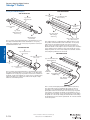
Receiver Patchcord
1
889D-F8AB-5
10 (32.8)
Cordsets Approximate Dimensions [mm (in.)]
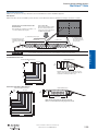
The GuardShield transmitter host patchcord has 4-pin DC micro
over-molded quick-disconnect connectors offered in lengths of
1/3 m, 1 m, and 2 m. The GuardShield receiver host patchcord has
8-pin DC micro over-molded quick-disconnect connectors offered in
lengths of 1/3 m, 1 m, and 2 m.
Transmitter Patchcord
5 (16.4)
Termination plug 8-pin M12
quick disconnect
Required for connection to 898D-81CU-DM
top connector of cascadable
receiver if cascade light
curtain is used as a
standalone system or as the
last segment pair in a
cascaded system.
Color
No. of Pins
Receiver
Brown
1
+24V
White
2
OSSD 2
Blue
3
0V
Black
4
OSSD 1
Grey
5
NC
Interconnecting Patchcords—ArmorBlock I/O Connection
Cat. No.
Description
889D-F5ACDM-0M3
Five-pin M12 patchcord, 0.3 m (12 in.)
889D-F5ACDM-1
Five-pin M12 patchcord, 1 m (39.37 in.)
889D-F5ACDM-2
Five-pin M12 patchcord, 2 m (78.74 in.)
889D-F5ACDM-5
Five-pin M12 patchcord, 5 m (196.85 in.)
889D-F5ACDM-10
Five-pin M12 patchcord, 10 m (393.7 in.)
Note: The GuardShield pairs with ArmorBlock Guard I/O Connectivity have a
5-pin M12 quick-disconnect connector on the receiver wired to allow
connection to the ArmorBlock 5-pin connector. The transmitter in that
GuardShield pair is a standard GuardShield transmitter with integrated laser
alignment system offered with a 4-pin M12 quick-disconnect connector. It is
possible to connect either a standard 4-pin M12 cordset or the 5-pin M12
quick-disconnect connector cordset or patchcord to this transmitter.
Principles
Cat. No.
2-Opto-electronics
Length [m (ft)]
Transmitter
Safety Switches
Wire Rating
General
Cable
Pin/Wire Color
Operator
Interface
Connector Style
Logic
Female Connector (Sensor End)
Face View of Female
Power
Note: A termination plug is not necessary for the cascadable transmitter.
Visit our website: www.ab.com/catalogs
R
Publication S117-CA001A-EN-P
2-19
Presence Sensing Safety Devices
POC Type 4 Safety Light Curtains
GuardShield
Termination Connector for Cascadable GuardShield Receiver (if it's a standalone pair) with ArmorBlock Guard I/O
Connectivity
General
Face View of Female
5
1
3
Description
Cat. No.
5-pin M12
Termination Adaptor
898D-418U-DM
2
4
Note: The cascadable GuardShield with ArmorBlock Guard I/O connectivity can be used as a standalone pair if the top connector on the receiver has a
termination adaptor connected. The cascadable transmitter does not require a termination adaptor.
Description
Cat. No.
440L-AF6101
2-Opto-electronics
Aluminum middle mounting bracket for vibratory
applications
440L-AF6108
Power supply: Output—24V DC, 3 Amps, 72 W
1606-XLP72E
Laser alignment tool
440L-ALAT
GuardShield laser alignment tool bracket
440L-AF6109
Mounting stand
440L-AMSTD
Vertical shock mount kit
440L-AF6120
Horizontal shock mount kit
440L-AF6121
Middle vertical mount kit
440L-AF6122
Middle horizontal mount kit
440L-AF6123
Operator
Interface
Steel L-shaped end cap mounting bracket (4 per
package)
Note: 4 brackets supplied with each GuardShield
pair.
Safety Switches
Principles
Optional Accessories
440L-AGWS0160
440L-AGWS0320
440L-AGWS0480
440L-AGWS0640
440L-AGWS0800
GuardShield weld shield (cat. no. is for a pair of
light curtains)
440L-AGWS0960
440L-AGWS1120
440L-AGWS1280
Logic
440L-AGWS1440
440L-AGWS1600
440L-AGWS1760
440L-AGST320
GuardShield Washdown Enclosure Kit
440L-AGST480
440L-AGST640
Note: Only for use with standard GuardShield light
curtain.
Power
8-pin M12 Receiver Termination Plug
(Required for top receiver connector if a cascaded
pair is used as a standalone or if it is the last pair
in a cascaded system.)
440L-AGST800
440L-AGST960
898D-81CU-DM
Visit our website: www.ab.com/catalogs
2-20
Publication S117-CA001A-EN-P
R
Presence Sensing Safety Devices
POC Type 4 Safety Light Curtains
GuardShield
Corner Mirror for Multi-Sided Guarding
Cat. No.
Wide Mirror Long-Range 4…15 m
Cat. No.
440L-AM0750300
440L-AM1250300
440L-P410320Y
440L-P2K‡0320YD
440L-AM0750450
440L-AM1250450
440L-P410480Y
440L-P2K‡0480YD
440L-P4A2500YD
440L-AM0750600
440L-AM1250600
440L-P410640Y
440L-P2K‡0640YD
440L-AM0750750
440L-AM1250750
440L-P410800Y
440L-P2K‡0800YD
440L-AM0750900
440L-AM1250900
440L-P410960Y
440L-P2K‡0960YD
440L-P4A3400YD
440L-AM0751050
440L-AM1251050
440L-P411120Y
440L-P2K‡1120YD
440L-AM0751200
440L-AM1251200
440L-P411280Y
440L-P2K‡1280YD
440L-AM0751350
440L-AM1251350
440L-P411440Y
440L-P2K‡1440YD
440L-AM0751500
440L-AM1251500
440L-P411600Y
440L-P2K‡1600YD
440L-AM0751650
440L-AM1251650
440L-P411760Y
440L-P2K‡1760YD
440L-AM0751800
440L-AM1251800
1 = J or K;
Safety Switches
= D or R;
‡ = A or D
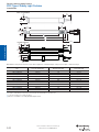
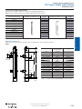
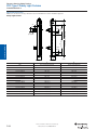
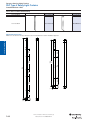
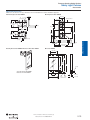
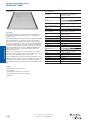
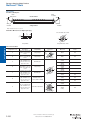
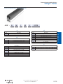
Approximate Dimensions
Dimensions are shown in mm (in.). Dimensions are not intended to be used for installation purposes.
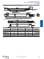
Standard GuardShield
80
(3.14) min.
11
(0.43)
Principles
Narrow Mirror Short-Range 0…4 m
440L-P410160Y
440L-P2K‡0160YD
2-Opto-electronics
GuardShield Light Curtain Cat. No.
General
Specially constructed glass mirrors for 2- and 3-sided safeguarding applications.
Note: Each mirror reduces maximum scan range by up to 15% per mirror. Each corner mirror suppled with two endcap mounting brackets.
40
(1.57)
To be used in
vibration applications
Operator
Interface
42
(1.65)
75
(2.95)
52
42
(2.05) (1.65)
Logic
A
B
C
Power
20
(0.79)
Visit our website: www.ab.com/catalogs
R
Publication S117-CA001A-EN-P
2-21
Presence Sensing Safety Devices
POC Type 4 Safety Light Curtains
GuardShield
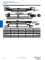
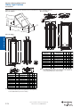
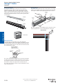
Remote Teach GuardShield
>80
(3.14)
11
(0.43)
General
52
(2.05)
75
(2.95)
40
(1.57)
Principles
42
(1.65)
20
(0.79)
A
B
C
254 (10)
Cascadable GuardShield
2-Opto-electronics
11
(0.43)
80
(3.14) min.
80
(3.14) min.
42
(1.65)
52
(2.05)
Safety Switches
32
(1.25)
Note: Middle mounting bracket should be used in vibration applications on GuardShield light curtain protective heights of 1120 mm and larger.
Type
A
Protective Height [mm]
B
Mounting Value [mm]
C
Total Length [mm]
Operator
Interface
440L-14‡0160YD
160 ±0.5§
276
312 ±1.5
440L-4‡0320YD
320 ±0.5
436
472 ±1.5
440L-4‡0480YD
480 ±0.5
596
632 ±1.5
440L-4‡0640YD
640 ±0.5
756
792 ±1.5
440L-4‡0800YD
800 ±0.6
916
952 ±1.5
440L-4‡0960YD
960 ±0.6
1076
1112 ±1.5
440L-4‡1120YD
1120 ±0.6
1236
1272 ±1.8
440L-4‡1280YD
1280 ±0.7
1396
1432 ±1.8
440L-4‡1440YD
1440 ±0.7
1556
1592 ±1.8
440L-4‡1600YD
1600 ±0.8
1716
1752 ±2.0
440L-4‡1760YD
1760 ±0.8
1876
1912 ±2.0
1 P = Pair, T = Transmitter, R = Receiver
P = Pair, T = Transmitter, R = Receiver, C = Host Pair, G = Host Transmitter, F = Host Receiver
‡ J = 14 mm resolution or K = 30 mm resolution
§ 160 mm is not available for cascading GuardShield light curtains.
Logic
Power
Visit our website: www.ab.com/catalogs
2-22
Publication S117-CA001A-EN-P
R
Presence Sensing Safety Devices
POC Type 4 Safety Light Curtains
GuardShield
Standard GuardShield Receiver with Integrated Laser Alignment
General
80 min
(3.14)
11 (0.43)
42
(1.65)
440L-R4JL0320YD shown
receiver
A
Middle Mounting Bracket
To Be Used in Vibration Applications
75
(2.95)
52
(2.05)
Principles
40
(1.57)
40
20
(0.79) (1.575)
B
C
A
Protective Height
B
Mounting
C
Total Length
D
Mounting
440L-P4*L0320YD
320±0.5
516
552±1.5
426
440L-P4*L0480YD
480±0.5
676
712±1.5
586
440L-P4*L0640YD
640±0.5
836
872±1.5
746
440L-P4*L0800YD
800±0.5
996
1032±1.5
906
440L-P4*L0960YD
960±0.5
1156
1192±1.5
1066
440L-P4*L1120YD
1120±0.5
1316
1352±1.5
1226
440L-P4*L1280YD
1280±0.5
1476
1512±1.5
1386
440L-P4*L1440YD
1440±0.5
1636
1672±1.5
1546
440L-P4*L1600YD
1600±0.5
1796
1832±1.5
1706
Operator
Interface
Type
Safety Switches
2-Opto-electronics
Standard GuardShield Transmitter with Integrated Laser Alignment
Power
Logic
J = 14 mm resolution, K = 30 mm resolution
Visit our website: www.ab.com/catalogs
R
Publication S117-CA001A-EN-P
2-23
Presence Sensing Safety Devices
POC Type 4 Safety Light Curtains
GuardShield
Cascadable GuardShield Receiver with Integrated Laser Alignment
11
(0.43)
80 min
(3.14)
General
80 min
(3.14)
42
(1.65)
440L-F4JL0320YD shown
receiver
A
40
(1.57)
Middle Mounting Bracket
To Be Used in Vibration Applications
75
(2.95)
Principles
52
(2.05)
40
20
(0.79) (1.575)
B
C
Cascadable GuardShield Transmitter with Integrated Laser Alignment
2-Opto-electronics
440L-G4JL0320YD shown
transmitter
440L-C4JL0320YD shown
* K = 30 mm resolution
* J = 14 mm resolution
* L = Laser
32
(1.25)
Safety Switches
Type
A
Protective Height
B
Mounting
C
Total Length
D
Mounting
440L-C4*L0320YD
320±0.5
516
552±1.5
426
440L-C4*L0480YD
480±0.5
676
712±1.5
586
440L-C4*L0640YD
640±0.5
836
872±1.5
746
440L-C4*L0800YD
800±0.5
996
1032±1.5
906
440L-C4*L0960YD
960±0.5
1156
1192±1.5
1066
440L-C4*L1120YD
1120±0.5
1316
1352±1.5
1226
440L-C4*L1280YD
1280±0.5
1476
1512±1.5
1386
440L-C4*L1440YD
1440±0.5
1636
1672±1.5
1546
440L-C4*L1600YD
1600±0.5
1796
1832±1.5
1706
Operator
Interface
J = 14 mm resolution, K = 30 mm resolution
Logic
Power
Visit our website: www.ab.com/catalogs
2-24
Publication S117-CA001A-EN-P
R
Presence Sensing Safety Devices
POC Type 4 Safety Light Curtains
GuardShield
Wiring Diagram for Connection of OSSDs Directly to Contactors (FSDs) with Restart Interlock
Wiring diagram is not intended to be used for installation purposes.
Transmitter
S2
(Start/Restart)
Receiver
2
1
Brown
General
+24V DC
Brown
Red
8
5
Grey
OSSD 1
Machine
Test
Signal
6
Bulletin 100S
Safety Contactors
or 700S Safety Contro
OSSD 2
Pink
Principles
K2
SI
Test
K1
Black
4
1
7
Blue
3
3
Yellow
MPCE/EDM
2-Opto-electronics
4
M
White
Blue
Auxilary
Signal
Green
24V Ground
1 Auxiliary output is nonsafety. Can be connected to a lamp, motor or status to a PLC.
Safety relay or safety contactor for OSSD 1 and OSSD 2 connection
Switch for external system test (optional)
Switch for reset of light curtain from start/restart interlock
Safety Switches
K1, K2
S1
S2
Wiring Diagram for Connection of OSSDs Directly to a Safety Relay Module
+24V DC
Receiver
8
4
6
5
1
7
Blue
3
3
Brown
Red
Yellow
Restart (not used)
EDM (not used)
Stop
800FM-E4MX01
Pink
Grey
White
L1 L2 L3
Aux Signal
To PLC
S11 S12 S52 A1
13
23
33
41
K1
Blue
Green
RP
MSR127TP
440R-N23132
K2
S21 S22 S34
889D-F4AC-2
K2
Operator
Interface
2
1
A2 14
24
44
42
889D-F8AC-2
Aux Signal
To PLC
K1
K2
Logic
Transmitter
Brown
Machine control system
can replace this circuit
arrangement.
K1
Start
800FM-F3MX10
M
100S-C43DJ404BC
Power
24V DC Com
Visit our website: www.ab.com/catalogs
R
Publication S117-CA001A-EN-P
2-25
Presence Sensing Safety Devices
POC Type 4 Safety Light Curtains
GuardShield
GuardShield Light Curtain Connected to MSR22LM with Two Sensor Muting
+24V DC
General
2 Brown
1 Brown
7 Blue
3 Blue
RECEIVER
POWER
MAINTAINED
P/B
SENDER
5 Grey 6 Pink
K1
MUTING
SENSOR
1
START
K2
A1+
X44
S43
S44
S12
S14
S21 S22
S24 S23
MUTING
SENSOR
2
S31 S32 S34 S33
S41
S42
Principles
MSR22LM
440R-P23071
A2-
M1
M2
48
13
23
K1
K2
33
34
24
14
58
MUTING
LAMP
"RESTART
REQUIRED"
LAMP
BULLETIN 100S
SAFETY CONTACTORS
OR 700S SAFETY RELAYS
2-Opto-electronics
DC COMMON
GuardShield Light Curtain Connected to MSR22LM with Four Sensor Muting
+24VDC
7
2
3
RECEIVER
Safety Switches
K1
START
A1+
X44
5
6
MUTING
SENSOR
3
K2
S43
S44
1
SENDER
S12
S14
S21
S22
MUTING
SENSOR
4
S24
S23
MUTING
SENSOR
1
S31
S32
MUTING
SENSOR
2
S34
S33
S41
S42
MSR22LM
440L-P23071
NOTES:
A2-
M1
M2
48
13
23
31
32
24
14
58
1. MUTING SENSORS ARE N.C. PNP TYPE
2. WIRE RESET SWITCH TO S43 & S44
WHEN EXTERNAL MONITORING IS NOT
REQUIRED. TERMINAL X44 IS NOT USED.
Operator
Interface
3. MUTING LAMP MUST MEET THE
FOLLOWING CURRENT SPECS:
MINIMUM CURRENT = 25mA
MAXIMUM CURRENT = 100mA
MUTING
LAMP
K1
K2
BULLETIN 100S
SAFETY CONTACTORS
OR 700S SAFETY RELAYS
RESTART
REQUIRED
LAMP
DC COMMON
Logic
Power
Visit our website: www.ab.com/catalogs
2-26
Publication S117-CA001A-EN-P
R
Presence Sensing Safety Devices
POC Type 4 Safety Light Curtains
GuardShield Safe 4
Specifications
Standards
EN/IEC 61496 Parts 1 and 2, UL 61496
Parts 1 and 2, UL1998
Safety Classification
Type 4 per IEC/EN61496. Category 4
device per EN 954-1, SIL 3 per IEC 61508,
PLe per EN/ISO 13849, EN/IEC 61496-1, 2, UL 61496-1, -2, UL 1998
Certifications
cULus Listed and CE Marked for all
applicable directives
General
Safety Ratings
Power Supply
Outputs
The Allen Bradley Guardmaster GuardShield Safe 4 is an
economical two box, Type 4 safety light curtain with ON/OFF
functionality. This basic, guard-only operating mode, safety light
curtain has an Integrated Laser Alignment system that simplifies the
alignment of each pair of light curtains. Visible laser beams are
activated by touching the laser at the finger symbol on front face of
the light curtains. Positioning of the transmitter and receiver laser
beams to their respective targets facilitates optimal alignment of
each Safe 4 pair. The Integrated Laser Alignment system also
quickly helps with the re-alignment of pairs when units are knocked
out of alignment during the course of the work process or when
corner mirrors are used.
Safety Outputs
2 PNP OSSD. 0.3 A, short-circuit protected
Output Voltage
>Usp (at load = 0.1 A)
Switching Current @ Voltage,
Min.
300 mA @ 24V DC
The GuardShield Safe 4 is designed to be used in a variety of
applications across a broad range of industries in medium to heavy
industrial environments. Offered with shock isolator kits for shock
and vibration applications and protective heights from
120…1920 mm in 120 mm increments assures that the correct size
of safety light curtain is available to suit the application requirement.
The GuardShield Safe 4, with an environmental rating of IP65, meets
all applicable global standards and can be used on or around
industrial machinery and equipment anywhere in the world.
Features
M12 connectors
Optically synchronized
Integrated laser alignment system
IP65 enclosure rating
Simple installation
cULus Listed and CE Marked for all applicable directives
Applications
Response Time
Varies by protective height, see
Installation Manual
Indicator LEDs
ON -State, OFF-State, internal error
Protected Height [mm (in.)]
120…1920 mm (4.7…75.6 in.) in 120 mm
(4.7 in.) increments
Resolution [mm (in.)]
14 mm (0.55 in.)
30 mm (1.18 in.)
Scanning Range
14 mm: 0…9 m (0…29.7 ft)
30 mm: 0…18 m (0…59 ft)
Synchronization
Optical, first beam adjacent to LEDs
Wavelength
950 nm
Environmental
Enclosure Type Rating
IP65
Relative humidity
15…95% (noncondensing)
Operating Temperature [C (F)]
0…55° (0…131°)
Vibration
IEC 60068-2-6 frequency 10…55 Hz;
amplitude 0.35 mm (0.01 in.)
Shock
IEC 60068-2-29; acceleration 10 g, pulse
duration 16 ms 10…55 Hz; amplitude
0.35 mm (0.01 in.)
Physical Characteristics
Mounting
Rear mounting, standard and adjustable
(180°)
Weight
Varies by protective height, see
Installation Manual
Housing Cross Section
30 x 40 mm (1.18 x 1.57 in.)
Connection Type
Transmitter: 5-pin M12 micro QD
Receiver: 5-pin M12 micro QD
Cable Length
30 m (98.4 ft) max.
ILAS Laser Class
Class 2, IEC 60825-1
Power
Logic
Metal working
Shears
Punch presses
Robot cells
Automated processes
Operating Characteristics
Operator
Interface
Description
< 10% of Usp
<500 mA (no load)
Principles
Power Consumption
24V DC ± 20%
2-Opto-electronics
Maximum Residual Ripple
Safety Switches
Input Power, Max.
Visit our website: www.ab.com/catalogs
R
Publication S117-CA001A-EN-P
2-27
Presence Sensing Safety Devices
POC Type 4 Safety Light Curtains
GuardShield Safe 4
Product Selection
Standard System
General
The Allen-Bradley Guardmaster GuardShield Safe 4 safety light curtains are offered in 14 mm and 30 mm resolutions, are ordered as pairs—
transmitter and receiver—and are shipped under one cat. no. Each GuardShield Safe 4 pair is shipped with standard mounting brackets. After
selecting the appropriate Safe 4 protected height and resolution, ensure that the appropriate cordsets, interfaces, and accessories are
ordered.
Cat. No.
Protected Height
[mm (in.)]
14 mm (0.55 in.)
Number of Beams
30 mm (1.18 in.)
Number of Beams
Pair Weight [kg (lbs)]
14 mm (0.55 in.)
30 mm (1.18 in.)
120 (4.7)
16
8
1.0 (2.2)
445L-P4L0120YD
445L-P4S0120YD
Principles
2-Opto-electronics
240 (9.4)
32
16
1.4 (3.1)
445L-P4L0240YD
445L-P4S0240YD
360 (14.2)
48
94
1.8 (4.0)
445L-P4L0360YD
445L-P4S0360YD
480 (19.9)
64
94
2.2 (4.9)
445L-P4L0480YD
445L-P4S0480YD
600 (23.6)
80
94
2.6 (5.7)
445L-P4L0600YD
445L-P4S0600YD
720 (28.3)
96
94
3.0 (6.6)
445L-P4L0720YD
445L-P4S0720YD
840 (33.1)
112
94
3.5 (7.7)
445L-P4L0840YD
445L-P4S0840YD
960 (37.8)
128
94
4.0 (8.8)
445L-P4L0960YD
445L-P4S0960YD
1080 (42.5)
144
94
4.0 (8.8)
445L-P4L1080YD
445L-P4S1080YD
1200 (47.2)
160
94
4.5 (9.9)
445L-P4L1200YD
445L-P4S1200YD
1320 (52.0)
176
94
5.0 (11.0)
445L-P4L1320YD
445L-P4S1320YD
1440 (56.7)
172
94
5.5 (12.1)
445L-P4L1440YD
445L-P4S1440YD
1560 (61.4)
188
102
6.0 (13.2)
445L-P4L1560YD
445L-P4S1560YD
1680 (66.1)
204
102
6.5 (14.3)
445L-P4L1680YD
445L-P4S1680YD
1800(70.9)
220
110
7.0 (15.4)
445L-P4L1800YD
445L-P4S1800YD
1920 (75.6)
236
118
7.5 (16.5)
445L-P4L1920YD
445L-P4S1920YD
Safety Switches
Note: The cat. nos. listed above are pair cat. nos., to specify a transmitter or receiver only, replace the "P" in the cat. no. with a "T" for transmitter or an "R" for
receiver.
Required Logic Interfaces
Description
Safety Outputs
Auxiliary Outputs
Terminals
Reset Type
Power Supply
Cat. Page No.
Cat. No.
Single-Function Safety Relays for 2 N.C. Contact Switch
MSR127RP
3 N.O.
1 N.C.
Removable
(Screw)
Monitored Manual
24V AC/DC
5-26
440R-N23135
MSR127TP
3 N.O.
1 N.C.
Removable
(Screw)
Auto./Manual
24V AC/DC
5-26
440R-N23132
MSR126
2 N.O.
None
Fixed
Auto./Manual
24V AC/DC
5-24
440R-N23117
MSR210P Base
2 N.C. only
2 N.O.
1 N.C. and 2 PNP
Solid State
Removable
Auto./Manual or
Monitored Manual
24V DC from the
base unit
5-82
440R-H23176
MSR220P Input
Module
—
—
Removable
—
24V DC
5-86
440R-H23178
MSR310P Base
MSR300 Series
Output Modules
3 PNP Solid State
Removable
Auto./Manual
Monitored Manual
24V DC
5-102
440R-W23219
MSR320P Input
Module
—
2 PNP Solid State
Removable
—
24V DC from the
base unit
5-106
440R-W23218
MSR22LM
2 N.O.
1 N.C.
Removable
Auto./Manual
24V DC
5-48
440R-P23071
MSR42 (requires
optical interface to
configure
445L-AF6150
2 PNP
2 PNP,
configurable
Removable
Auto./manual or
manual monitored
24V DC
5-52
440R-P226AGS-NNR
Modular Safety Relays
Operator
Interface
Muting Modules
Logic
Power
Visit our website: www.ab.com/catalogs
2-28
Publication S117-CA001A-EN-P
R
Presence Sensing Safety Devices
POC Type 4 Safety Light Curtains
GuardShield Safe 4
Cordsets—Transmitters and receivers both use 5-pin M12 cordsets
Straight Female
Nonshielded
5
Cable
Pin/Wire Color
Wire Rating
1 Brown
2 White
3 Blue
4 Black
5 Grey
22 AWG
250V
4A
1
4
3
Straight Female
Shielded
1 Brown
2 White
3 Blue
4 Black
5 Grey
22 AWG
22 AWG
300V
4A
Length [m (ft)]
Cat. No.
2 (6.56)
889D-F5AC-2
5 (16.4)
889D-F5AC-5
10 (32.8)
889D-F5AC-10
15 (49.2)
889D-F5AC-15
20 (65.6)
889D-F5AC-20
30 (98.4)
889D-F5AC-30
2 (6.56)
889D-F5EC-2
5 (16.4)
889D-F5EC-5
10 (32.8)
889D-F5EC-10
15 (49.2)
889D-F5EC-15
20 (65.6)
889D-F5EC-20
30 (98.4)
889D-F5EC-30
Principles
2
Connector Style
2-Opto-electronics
Female Connector (Sensor End)
Face View of Female
General
Note: Unshielded cordsets are most commonly used for safety light curtains, however, shielded cordsets are also offered to increase
immunity to electrical interference.
Cordsets Approximate Dimensions [mm (in.)]
Dimensions are not intended to be used for installation purposes.
47 (1.85)
14
(0.56)
Power
Logic
Operator
Interface
Safety Switches
Straight Female
Visit our website: www.ab.com/catalogs
R
Publication S117-CA001A-EN-P
2-29
Presence Sensing Safety Devices
POC Type 4 Safety Light Curtains
GuardShield Safe 4
Optional Accessories
Description
Cat. No.
General
Principles
2-Opto-electronics
Safety Switches
Operator
Interface
Standard kit (4 pieces — supplied with each pair)
445L-AF6140
180° Adjustable kit (two kits required per pair)
445L-AF6141
Shock Mount Kit
(2 kits required per pair of light curtains)
445L-AF6142
Vertical mounting kit (two kits required per pair)
445L-AF6144
MSR42 Multifunction Module (requires Cat. No. 440L-AF6150
to program)
440R-P226AGS-NNR
MSR45E — Safety relay expansion module for MSR42
440R-P4NANS
USB optical interface software configuration tool used to
configure the MSR42
(Used to configure the MSR42 module or get diagnostic
information from the Safe 4.)
445L-AF6150
Ribbon cable — to connect one MSR45E to an MSR42
440R-ACABL1
Ribbon cable — to connect two MSR45Es to an MSR42
440R-ACABL2
Ribbon cable — to connect three MSR45Es to an MSR42
440R-ACABL3
Mounting stand
(Comes with hardware to level base and two GuardShield
mounting brackets.)
440L-AMSTD
Logic
Power
Visit our website: www.ab.com/catalogs
2-30
Publication S117-CA001A-EN-P
R
Presence Sensing Safety Devices
POC Type 4 Safety Light Curtains
GuardShield Safe 4
Corner Mirror for Multi-Sided Guarding
Cat. No.
Wide Mirror Long-Range 4…15 m
Cat. No.
440L-AM0750300
440L-AM1250300
360 (14.2)
440L-AM0750450
440L-AM1250450
480 (19)
440L-AM0750600
440L-AM1250600
600 (24)
440L-AM0750750
440L-AM1250750
720/840 (28/33)
440L-AM0750900
440L-AM1250900
960 (38)
440L-AM0751050
440L-AM1251050
1080 (43)
440L-AM0751200
440L-AM1251200
440L-AM0751350
440L-AM1251350
440L-AM0751500
440L-AM1251500
1560 (61)
440L-AM0751650
440L-AM1251650
1680 (66)
440L-AM0751800
440L-AM1251800
1800/1920 (70.9/75.6)
Not available
Not available
2-Opto-electronics
1200 (47)
1320/1440 (52/57)
Approximate Dimensions
Dimensions are shown in mm (in.). Dimensions are not intended to be used for installation purposes.
Safe 4
35
(1.38)
30
(1.18)
14.75
(0.58)
alignment
module
laser
A
protection length
alignment
module
laser
20 10
(0.79) (0.39)
B
profile length according to table
14.75
(0.58) 145
(5.71)
25
(0.98)
Type
A
Protective Height
[mm (in.)]
B
Profile Length [mm (in.)]
290 (11.4)
445L-P410120YD
120 (4.7)
445L-P410240YD
240 (9.4)
410 (16.1)
445L-P410360YD
360 (14.2)
530 (20.9)
445L-P410480YD
480 (18.9)
650 (25.6)
445L-P410600YD
600 (23.6)
771 (30.4)
445L-P410720YD
720 (28.3)
891 (35.1)
445L-P410840YD
840 (33.1)
1011 (39.8)
445L-P410960YD
960 (37.8)
1131 (44.5)
445L-P411080YD
1080 (42.5)
1252 (49.3)
445L-P411200YD
1200 (47.2)
1372 (54.0)
445L-P411320YD
1320 (51.9)
1492 ( 58.7)
445L-P411440YD
1440 (56.7)
1612 (63.5)
445L-P411560YD
1560 (61.4)
1733 (68.2)
445L-P411680YD
1680 (66.1)
1853 (72.9)
445L-P411800YD
1800 (70.8)
1973 (77.7)
445L-P411920YD
1920 (75.6)
2093 (82.4)
Safety Switches
Narrow Mirror Short-Range 0…4 m
120/240 (4.7/9.4)
Operator
Interface
GuardShield Safe 2/Safe 4
Protected Height [mm (in.)]
Principles
Note: Each mirror reduces maximum scan range by approximately 15% per mirror.
General
Specially constructed glass mirrors for 2- and 3-sided safeguarding applications.
1 For 14 mm resolution replace with an "L." For 30 mm resolution replace
40
(1.56)
with an "S." Example: Cat. No. 445L-P4S0480YD (for 30 mm resolution).
Power
Logic
30
(1.18)
3
(0.12)
Visit our website: www.ab.com/catalogs
R
Publication S117-CA001A-EN-P
2-31
Presence Sensing Safety Devices
POC Type 4 Safety Light Curtains
GuardShield Safe 4
Wiring Diagram for Connection to MSR126
Wiring diagram is not intended to be used for installation purposes.
Brown
General
+24V
2
4
4
5
Reset
A1 S11 S12 S33 13
Principles
Receiver
Grey
Black
L1
L2
L3
1
Transmitter
Brown
Test Circuit
Safe 4
1
3
3
2
23
Grey
5
K1
K2
MSR126
A2 S21 S22 S34 14
24
Blue
Blue
2-Opto-electronics
889D-F5AC-2
Cable
White
K1
K2
GND = 0V
3
Brown
Safe 4
2
4
2
K1
L1
L2
L3
4
5
Grey
White
Operator
Interface
Receiver
5
1
1
S11 S12 S52
A1
13
23
33
41
3
2
A2
Logic
14
24
K1
K2
34
42
Blue
899D-F5AC-2
Cable
S21 S22 S34
K1
K2
MSR127
3
Blue
1
K2
Black
4
Transmitter
Grey
Start
Stop
+24V
Brown
Test Circuit
Safety Switches
Wiring Diagram for Connection to MSR127
Aux Signal
to PLC
GND = 0V
Power
Visit our website: www.ab.com/catalogs
2-32
Publication S117-CA001A-EN-P
R
Presence Sensing Safety Devices
POC Type 4 Safety Light Curtains
A GuardShield Cascadable Micro 400 safety light curtain system is
comprised of one or two pair of Cascadable Micro 400 light curtains
as well as a standard Micro 400 pair as the last segment pair in the
cascaded system.
GuardShield Micro 400 cascaded pairs are offered in both 14 mm
and 30 mm resolutions in limited protected heights which are listed
in the table below. It is possible to mix 14 mm and 30 mm resolution
pairs in a cascaded Micro 400 system.
The Micro 400 requires a dedicated controller. The MSR41 controller
is used for on/off application and the MSR42 can also be used as a
multi-function safety module, allowing the connection of additional
safety light curtains, safety laser scanner, or any safety device with
two Output Signal Switch Devices (OSSD) outputs, or two contacts,
such as E-stops and enabling switches.
There are a number of operating modes that can be configured with
the MSR42 controller. EDM, START/Restart interlock, fixed and
floating blanking and muting are possible.
The Micro 400 transmitter and receiver are offered with 8-pin M12
connectors at the end of 500 mm (19.8 in.) integrated cables. The
patchcords to connect the transmitter and receiver to the controller
are the same and are offered in 3, 5, and 8 m (9.8, 16.4, and 26.2 ft)
lengths. These patchcords are configured on one end with M12
connectors (which mate to the integrated pigtail connectors) and
RJ45 connectors on the opposite end (which plug into the MSR42
controller).
Cascadable System
When connecting two cascadable segments together, the resultant
cable length between segments is 1000 mm (39.6 in.).
If an additional length between segment pairs is required, Rockwell
Automation offers an M12-to-M12 patchcord in 1 m (39.37 in.) and
3 m (118.1 in.) lengths (Cat. Nos. 445L-AC8PC1 or 445L-AC8PC3).
IMPORTANT
The maximum cascaded Micro 400
system length can not exceed 10 m as
measured between the RJ45 connection
at the MSR42 controller to the last beam
in the standard Micro 400, including all
cable lengths. The maximum number of
beams in a cascaded Micro 400 system
can not exceed 255 beams.
Features
Very small profile 15 x 20 mm (0.59 x 0.79 in.)
M12 connector on 20 inch pigtails
Minimal dead space of optic heads
Applications
Light assembly machines/equipment
Semi-conductor
Micro-electronics
Pharmaceutical
Power
The GuardShield Micro 400 is also offered in a cascadable
configuration. GuardShield Cascadable Micro 400 safety light
curtains allow the interconnection of multiple segments of the Micro
400 safety light curtain with a common pair of safety outputs. This
cascadable configurability of the GuardShield Micro 400 reduces
overall system wiring and allows the GuardShield Micro 400 to be
fitted into a variety of applications where the safety distances for
mounting the light curtain may allow personnel to stand between
the sensing field of the light curtain and the hazard or where
multiple sided guarding is required and the use of corner mirrors is
not possible.
The GuardShield Cascadable Micro 400 system operates as a single
light curtain pair with a common set of OSSDs. Each segment pair
is connected in series making the response time of the complete
system the sum of each segment pair, plus the response time of the
MSR41 or MSR42 and other safety devices in the stop circuit.
Operator
Interface
Protective heights are offered from 150…1200 mm (5.91…47.2 in.)
in 150 mm (5.91 in.) increments. The compact housing size allows
the GuardShield Micro 400 to be mounted in areas where standard
safety light curtains may not be able to be mounted due to space
constraints. It is also possible to recess the GuardShield Micro 400
transmitter and receiver into machine frames.
A cascadable pair of GuardShield Micro 400 light curtains has a
500 mm (19.8 in.) pigtail with a female M12 QD on the bottom of the
Micro 400 light curtain and a 500 mm (19.8 in.) pigtail with a male
M12 QD attached to the top of the Micro 400 transmitter and
receiver.
Logic
Description
The GuardShield Micro 400 is an economical three-box (transmitter,
receiver and controller) Type 4 safety light curtain offered in a small
profile (15 x 20 mm (0.59 x 0.79 in.)) housing. Designed for use in
benign industrial environments (IP54), this light-duty safety light
curtain system is targeted to the semi-conductor, micro electronic
and small assembly machine markets.
2-Opto-electronics
The cascadable Micro 400 safety light curtains are ordered as pairs
(transmitter and receiver) and are shipped under one cat. no. After
selecting the appropriate light curtain cat. nos. for a cascaded Micro
400 system, select the standard Micro 400 pair as the last segment
in the cascaded system and also select interconnecting patchcords.
Principles
The standard GuardShield Micro 400
must always be the last segment in a
cascaded Micro 400 system.
Safety Switches
IMPORTANT
General
GuardShield Micro 400
Visit our website: www.ab.com/catalogs
R
Publication S117-CA001A-EN-P
2-33
Presence Sensing Safety Devices
POC Type 4 Safety Light Curtains
GuardShield Micro 400
Specifications
Safety Ratings
General
Standards
IEC/EN61496 Parts 1 and 2. UL61496 Parts
1 and 2, UL1998
Safety Classification
Type 4 per IEC/EN61496. Category 4
device per EN 954-1, SIL 3 per IEC 61508,
PLe per EN/ISO 13849
Certifications
cULus Listed, TÜV, CE Marked for all
applicable directives
Power Supply
Input power from MSR41 or MSR42
controller
Input Power, Max.
24V DC ±15%
Principles
Maximum Residual Ripple
5% of Vss
Power Consumption
0.07 A max. (no load)
Outputs
Micro 400 Outputs
Data output to controller (MSR41 or
MSR42)
2-Opto-electronics
MSR41/MSR42 Outputs
Two 400 mA OSSD
Non-Safety Outputs
Auxiliary outputs from MSR41 or MSR42
controller—2 configurable 100 mA, outputs
Switching Current @ Voltage,
Max.
400 mA @ 24V DC
Operating Characteristics
Response Time
14 mm: 14…42 ms; 30 mm; 12…23 ms,
varies by protective height and resolution
Indicator LEDs—light curtains
ON -State, OFF-State, Intensity
Protected Height [mm (in.)]
150…1200 mm (5.91…47.24 in.) in 150 mm
increments
Safety Switches
Resolution [mm (in.)]
14 (0.55), 30 (1.18)
Scanning Range/Resolution
14 mm (0.55 in.) resolution: 0…5 m (16.4 ft)
30 mm (1.18 in.) resolution: 0…5 m (16.4 ft)
Synchronization
Electrical through MSR41 or MSR42
Wavelength
940 nm
Environmental
Enclosure Type Rating
Micro 400 is IP54; MSR41 and MSR42 are
IP20
Relative Humidity
15…95% (noncondensing)
Operator
Interface
Operating Temperature [C (F)]
0…55 ° (14…131 °)
Vibration
IEC 60068-2-6; Frequency 10…55 Hz;
Amplitude 0.35 mm (0.01 in.)
Shock
IEC 60068-2-29; Acceleration 10 g, pulse
duration 16 ms 10…55 Hz; Amplitude
0.35 mm (0.01 in.)
Physical Characteristics
Mounting
180° adjustable mounting brackets
supplied
Logic
Weight
Varies by protective height
Housing Cross Section
15 mm x 20 mm (0.59…0.79 in.)
Connection Type
Transmitter/receiver: 8-pin M12 micro QD
Cable Length
For MSR41 and MSR42: 3, 5, and 8 m (9.8,
16.4, and 26.2 ft), max. Total system length
can not exceed 10 m (32.8 ft).
Cascadable Patchcords
1 and 3 m (39.37 and 118.1 in.) M12 to
M12 patchcords.
Total system length cannot exceed 10 m
(32.8 ft) including protective height of Micro
400 (500 mm (19.8 in.)), integrated cables
and patchcords from M12 connector to
MSR41 or MSR42.
Power
Visit our website: www.ab.com/catalogs
2-34
Publication S117-CA001A-EN-P
R
Presence Sensing Safety Devices
POC Type 4 Safety Light Curtains
GuardShield Micro 400
The maximum length of a GuardShield Micro 400 system is limited to 10 m. This total length includes the
length from the last beam in the light curtain housing plus the length of the pigtail cable and the patchcord
length.
IMPORTANT
Standard System
General
Product Selection
Number of Beams
Cat. No.
Protected Height
[mm (in.)]
Resolution
[mm (in.)]
Number of Beams
Cat. No.
150 (5.9)
14 (0.55)
15
445L-P4C0150FP
150 (5.9)
30 (1.18)
6
445L-P4E0150FP
300 (11.8)
14 (0.55)
30
445L-P4C0300FP
300 (11.8)
30 (1.18)
12
445L-P4E0300FP
450 (17.7)
14 (0.55)
45
445L-P4C0450FP
450 (17.7)
30 (1.18)
18
445L-P4E0450FP
600 (23.6)
14 (0.55)
60
445L-P4C0600FP
600 (23.6)
30 (1.18)
24
445L-P4E0600FP
750 (29.5)
14 (0.55)
75
445L-P4C0750FP
750 (29.5)
30 (1.18)
30
445L-P4E0750FP
900 (35.4)
14 (0.55)
90
445L-P4C0900FP
900 (35.4)
30 (1.18)
36
445L-P4E0900FP
1050 (41.3)
14 (0.55)
105
445L-P4C1050FP
1050 (41.3)
30 (1.18)
42
445L-P4E1050FP
1200 (47.2)
14 (0.55)
120
445L-P4C1200FP
1200 (47.2)
30 (1.18)
48
445L-P4E1200FP
IMPORTANT
The GuardShield Micro 400 requires a dedicated controller (MSR41 or MSR42) as well as transmitter and
receiver patchcords.
Cascadable System
The Allen Bradley Guardmaster GuardShield Cascadable Micro 400 safety light curtains are offered in limited protective heights in 14 mm and
30 mm resolutions.They are most commonly ordered as pairs (cascadable transmitter and cascadable receiver) and are shipped under one
part number. Each GuardShield Cascadable Micro 400 pair is shipped with mounting brackets. After selecting the appropiate cascadable pair
cat. no., ensure that the dedicated safety controller (MSR41 or MSR42), appropiate cables, interfaces and accessories are ordered as well.
Protected Height
[mm (in.)]
Resolution
[mm (in.)]
Number of Beams
Cat. No.
Protected Height
[mm (in.)]
Resolution
[mm (in.)]
Number of Beams
Cat. No.
150 (5.9)
14 (0.55)
15
445L-C4C0150FP
150 (5.9)
30 (1.18)
6
445L-C4E0150FP
300 (11.8)
14 (0.55)
30
445L-C4C0300FP
300 (11.8)
30 (1.18)
12
445L-C4E0300FP
450 (17.7)
14 (0.55)
45
445L-C4C0450FP
600 (23.6)
30 (1.18)
24
445L-C4E0600FP
600 (23.6)
14 (0.55)
60
445L-C4C0600FP
900 (35.4)
30 (1.18)
36
445L-C4E0900FP
900 (35.4)
14 (0.55)
90
445L-C4C0900FP
1200 (47.2)
30 (1.18)
48
445L-C4E1200FP
1200 (47.2)
14 (0.55)
120
445L-C4C1200FP
Length, see table; tolerance 0/+50 mm
15 (0.59)
Dia.
80
(3.15)
Description
Cat. No.
1 m (39.37 in.) patchcord
445L-AC8PC1
3 m (118.11 in.) patchcord
445L-AC8PC3
5 m (196.85 in.) patchcord
445L-AC8PC5
51.3
(2.02)
Logic
32.2
(1.27)
Cascadable Patchcords
Power
50.2
(1.98)
17
(0.67)
Dia.
—
Operator
Interface
Micro 400 Patchcord for Interconnecting Cascaded
Segments (if required)
2-Opto-electronics
Resolution
[mm (in.)]
Safety Switches
Protected Height
[mm (in.)]
Principles
The Allen-Bradley Guardmaster GuardShield Micro 400 safety light curtains are offered in 14 and 30 mm resolution, are ordered as pairs
(transmitter and receiver) and are shipped under one cat. no. Each GuardShield Micro 400 pair is shipped with 180° adjustable mounting
brackets. After selecting the appropriate pair by cat. no., ensure that the dedicated safety controller (MSR42), required cables, interfaces and
accessories are ordered as needed.
Visit our website: www.ab.com/catalogs
R
Publication S117-CA001A-EN-P
2-35
Presence Sensing Safety Devices
POC Type 4 Safety Light Curtains
GuardShield Micro 400
Micro 400 IP69K Light Curtains
General
These patchcords are configured on one end with M12 connectors,
which mate to the integrated pigtail connectors and RJ45
connectors on the opposite end. These connectors plug into the
MSR41 or MSR42 controller.
The GuardShield Micro 400 is offered with the transmitter and
receiver sealed in clear acrylic tubes with an environmental rating of
IP69K. These IP69K Micro 400 light curtains are factory sealed and
are ordered as pairs. They are offered in a 14 mm resolution in
protected heights of 300 mm (11.8 in.), 600 mm (23.6 in.), 900 mm
(35.4 in.) and 1200 mm (47.2 in.) with an operating range of five
meters.
Areas of Use
Light assembly machines/equipment
Semi-conductor
Micro-electronics
Pharmaceutical
Filling systems
Clean rooms
Food processing
The required MSR 41 or MSR42 controllers maintain the IP20 rating
and must be mounted in a suitable enclosure.
Principles
The Micro 400 IP69K transmitter and receiver are both offered with
eight pin M12 connectors at the end of 500 mm (19.8 in.) integrated
cables. The patchcords to connect the transmitter and receiver to
the controller are the same cat. no. and are offered in 3 m (9.8 ft),
5 m (16.4 ft), and 8 m (26.2 ft) lengths.
2-Opto-electronics
Protected Height [mm (in.)]
Resolution [mm (in.)]
Number of Beams
Cat. No.
300 (11.8)
14 (0.55)
30
445L-P4C0300KD
600 (23.6)
14 (0.55)
60
445L-P4C0600KD
900 (35.4)
14 (0.55)
90
445L-P4C0900KD
1200 (47.2)
14 (0.55)
120
445L-P4C1200KD
Required Micro 400 Controller—Select One
Safety Switches
Mounting
Size
Cat. No.
35 mm DIN Rail
22.5 mm
440R-P221AGS
35 mm DIN Rail
22.5 mm
440R-P226AGS-NNR
MSR41—ON/OFF
MSR42—Multi-functional module
Optional Safety Relay Interfaces
Operator
Interface
Relay
Input Voltage
Reset
Outputs
Cat. No.
Supplied by MSR41 or MSR42
Determined by MSR41 or MSR42
2 N.O.
440R-P4NANS
MSR45E
Safety Relay
Expansion Model
Possible Logic Interfaces
Logic
Description
Safety Outputs
Auxiliary Outputs
Terminals
Reset Type
Power Supply
Cat. Page No.
Cat. No.
Single-Function Safety Relays for 2 N.C. Contact Switch
MSR127RP
3 N.O.
1 N.C.
Removable (Screw)
Monitored Manual
24V AC/DC
5-26
440R-N23135
MSR127TP
3 N.O.
1 N.C.
Removable (Screw)
Auto./Manual
24V AC/DC
5-26
440R-N23132
MSR126
2 N.O.
None
Fixed
Auto./Manual
24V AC/DC
5-24
440R-N23117
Power
Visit our website: www.ab.com/catalogs
2-36
Publication S117-CA001A-EN-P
R
Presence Sensing Safety Devices
POC Type 4 Safety Light Curtains
GuardShield Micro 400
Face View M12 Connector
Face View RJ45 Connector
1
8
3
7
4
6
Pinning table:
-----------------1: blue
2: grey
3: green
4: white
5: black
6: pink
7: brown
8: yellow
Shield: Braid wires
Pinning table:
-----------------1:
2:
3:
4:
5:
6:
7:
8:
blue
grey
green
white
black
pink
brown
yellow
Shield: Braid wires
8
7
6
5
1
2
3
4
Cat. No.
445L-AC8RJ1
2 m patchcord, PVC jacket
445L-AC8RJ2
3 m patchcord, PVC jacket
445L-AC8RJ3
5 m patchcord, PVC jacket
445L-AC8RJ5
8 m patchcord, PVC jacket
445L-AC8RJ8
Principles
2
Description
1 m patchcord, PVC jacket
5
17 (0.67)
2-Opto-electronics
150
(5.91)
6.3 (0.25) dia.
Patchcord [mm (in.)]
Cable
General
Standard Micro 400 Patchcords—Required (Transmitters and receivers both use 8-pin M12 to RJ45 patchcords)
Ferrite
32.5
(1.28)
The MSR41 or MSR42 can have up to three MSR45E safety relays inter-connected. Each module requires a ribbon cable connector to make
the interconnection. The table shows the cat. no. for each ribbon cable connector as well as the optical interface for the programming of the
MSR42. Programming of the MSR42 is only necessary for advanced operating modes or connection of additional devices.
Cat. No.
Ribbon cable—for one MSR45E
440R-ACABL1
Ribbon cable—for two MSR45Es
440R-ACABL2
Ribbon cable—for three MSR45Es
440R-ACABL3
USB optical interface software configuration tool
used to configure the MSR42
445L-AF6150
Operator
Interface
Description
Safety Switches
Optional Safety Relay Interface (accessories for MSR41 or MSR42 Controllers)
Power
Logic
Note: The configuration software can be downloaded at www.ab.com/safety.
Visit our website: www.ab.com/catalogs
R
Publication S117-CA001A-EN-P
2-37
Presence Sensing Safety Devices
POC Type 4 Safety Light Curtains
GuardShield Micro 400
Optional Accessories
Description
Cat. No.
General
Principles
Adjustable 180° bracket kit (two per kit) supplied
with each pair
Two kits required per pair
445L-AF6143
Flat bracket kit (two per kit)
Two kits per pair
445L-AF6145
Adjustable flat bracket (two per kit)
Two kits required per pair
445L-AF6149
IP69K mounting bracket kit (two kits per pair
supplied with each pair)
445L-AF6160
2-Opto-electronics
Corner Mirror for Multi-Sided Guarding
Specially constructed glass mirrors for 2- and 3-sided safeguarding applications.
IMPORTANT
Each mirror reduces maximum scan range by 10% per mirror.
GuardShield Micro 400
Protected Height [mm (in.)]
Narrow Mirror Short-Range 0…4 m
Cat. No.
Safety Switches
150 (5.9)/300 (11.8)
440L-AM0750300
450 (17.7)
440L-AM0750450
600 (23.6)
440L-AM0750600
750 (29.5)
440L-AM0750750
900 (35.4)
440L-AM0750900
1050 (41.3)
440L-AM0751050
1200 (47.2)
440L-AM0751200
Operator
Interface
Logic
Power
Visit our website: www.ab.com/catalogs
2-38
Publication S117-CA001A-EN-P
R
Presence Sensing Safety Devices
POC Type 4 Safety Light Curtains
GuardShield Micro 400
Approximate Dimensions
Dimensions are shown in mm (in.). Dimensions are not intended to be used for installation purposes.
Safety Light Curtains—Standard
51.3
(2.02)
General
Safety Light Curtains—Cascadable
51.3
(2.02)
Principles
50
(1.97)
455
(17.91)
32.5
(1.28)
14.2
(0.56)
455
(17.91)
15.5
(0.61)
19.8
(0.78)
2-Opto-electronics
A - protection length according to table
1.5
(0.06)
B - profile length according to table
27.8
(1.09)
15.5
(0.61)
15.5
(0.61)
19.8
(0.78)
27.8
(1.09)
Safety Switches
A - protection length according to table
B - profile length according to table
27.8
(1.09)
Operator
Interface
455
(17.91)
51.3
(2.02)
Type
A
Protective Height [mm]
B
Profile Length [mm]
445L-4‡0150FB
150
151.5 ±0.3
445L-4‡0300FB
300
301 ±0.3
445L-4‡0450FB
450
451 ±0.3
445L-4‡0600FB
600
601 ±0.3
445L-4‡0750FB
750
751 ±0.3
445L-4‡0900FB
900
901 ±0.3
445L-4‡1050FB
1050
1051 ±0.3
445L-4‡1200FB
1200
1201 ±0.3
Logic
15
(0.59)
Power
P = Standard pair, C = Cascadable pair
‡ C = 14 mm, E = 30 mm
Visit our website: www.ab.com/catalogs
R
Publication S117-CA001A-EN-P
2-39
Presence Sensing Safety Devices
POC Type 4 Safety Light Curtains
GuardShield Micro 400
IP69K Micro 400
General
18
(0.71)
500
(19.7)
28.4 (1.12) Dia.
System length B
System length B - 38 (1.5)
Principles
17.5
(0.69)
29.5
(1.16)
Protection High A
Wiring Diagram for Connection to MSR126 Relay
Receiver
+24V DC
Emitter
RJ-45
Safety Switches
LAMP
Blue
GPIO4
Micro 400
GPIO3
Reset
GPIO2
L1 L2 L3
GPIO1
OSSD2
OSSD1
MSR42
2-Opto-electronics
Wiring diagram is not intended to be used for installation purposes.
A1 S11 S12 S33 13
23
Allen-Bradley
INFO2
K1
INFO1
IN2
MSR126R
A2 S21 S22 S34 14
IN1
0V/GND
K2
24
M
White
+24V
Operator
Interface
Motor
K1
RJ-45
K2
GND=0V
Micro 400 with MSR42 and MSR126R for Monitored Manual Reset with Monitored Output
Logic
Power
Visit our website: www.ab.com/catalogs
2-40
Publication S117-CA001A-EN-P
R
Presence Sensing Safety Devices
POC Type 4 Safety Light Curtains
GuardShield Micro 400
Wiring Diagram for Connection to MSR45E Expansion Module
General
+24V DC
RJ-45
Blue
GPIO3
Micro 400
.
.
GPIO1
.
.
OSSD2
.
.
.
.
.
.
13
.
.
14
OSSD1
MSR42
GPIO2
INFO2
INFO1
K3
K4
IN2
L1 L2 L3
C
IN1
0V/GND
Principles
GPIO4
K4
23
White
2-Opto-electronics
LAMP
Start
MSR45E
Emitter
Receiver
Ribbon Cable for Extender
24
+24V
K3
C
RJ-45
M
GND = 0V
Micro 400 with MSR42 Add-on MSR45E for Manual Reset with Start Release
Wiring Diagram for Connection of MSR42 to Contactor if EDM Is Activated
Transmitter
Safety Switches
24V DC
Receiver
Start
Lamp
GPIO4 Blue
GPIO3
GPIO2
GPIO1
Operator
Interface
OSSD2
OSSD1
Info2
K1
K2
Info1
In2
In1
0V
White
24 V
Logic
K2
K1
M
Power
0V DC
Visit our website: www.ab.com/catalogs
R
Publication S117-CA001A-EN-P
2-41
Presence Sensing Safety Devices
POC Type 2 Safety Light Curtains
GuardShield Type 2
Overview
General
The Allen-Bradley Guardmaster GuardShield Type 2 safety light
curtain is a new addition to the ABGM portfolio of Opto-Electronic
safety devices. The “Type 2” designation means that this particular
safety light curtain meets a lesser requirement for performance
under fault conditions than the GuardShield Type 4. As a result, the
GuardShield Type 2 safety light curtain can only be applied in
applications where a formal risk assessment has determined that a
Type 2 device is sufficient to meet the level of risk posed by the
hazard.
Principles
There are a number of regulations that discuss risk assessment. The
US based methods of conducting risk assessments which provide
guidance for the determination of the level of risk to personnel can
be found as follows:
ANSI TR3—for machinery
ANSI/RIA 15.05—for the Robotics industry
ANSI/ISO 12100-1 Safety of Machinery
2-Opto-electronics
Typically in North America the use of Type 2 light curtains is not
allowed for machinery or equipment covered by ANSI/OSHA
regulations and standards whose requirement for performance
under fault conditions is "control reliability." Type 2 light curtains do
not meet the requirements of "control reliability."
A Type 2 device requires the need for a periodic test of the system
prior to a demand on the system, i.e., interruption of the light
curtain's sensing field. This periodic test may be initiated by a
simple manually operated switch (e.g., pushbutton) or by a more
complex automatically controlled PLC.
Ideally the periodic test will be twice the operator interface
frequency of exposure to the hazard.
The Type 4 device is required to detect a fault in its safety circuitry
and immediately switch to a lock-out condition when the fault
occurs. The fault detection is assured through diverse redundancy
and cross monitoring of the internal circuit. A Type 4 device will fail
to a safe state in the presence of an accumulation of undetected
faults.
IMPORTANT
Type 2 safety light curtains do not meet
OSHA regulations nor ANSI published
standards, which define the requirements
of “Control Reliability,” therefore it is not
allowable to use a Type 2 safety light
curtain device on equipment or machinery
that requires “Control Reliability.”
The European Union requires the Risk Assessment be performed
per EN ISO 14121 "Principles for Risk Assessment."
Safeguarding of the machine must be appropriate to the foreseeable
risks and identified hazards. The level(s) of risk determined from the
completion of a formal risk assessment indicate the level of the
safety device required. In many instances it is necessary to use a
combination of safety devices for adequate protection of personnel
from hazards based on the risk assessment.
Safety Switches
What Is "Type 2" and "Type 4"
Three types of safety ESPEs (Electro-Sensitive Protective
Equipment) are defined within International and European standard
IEC/EN 61496 Parts 1 and 2. This standard specifies the
requirements for the design, construction, testing and performance
of ESPEs—designed specifically to detect persons as part of a
safety related system. The three types differ in their performance in
the presence of faults and under influences from environmental
conditions.
A Type 2 safety light curtain requires:
Operator
Interface
A single fault resulting in the loss of detection capability,
Failure of the OSSDs to go to the OFF state,
Shall cause the light curtain to lock out as a result of the cycling of
power, the next periodic test, or the interruption of the sensing
function.
Logic
Power
Visit our website: www.ab.com/catalogs
2-42
Publication S117-CA001A-EN-P
R
Presence Sensing Safety Devices
POC Type 2 Safety Light Curtains
GuardShield Type 2
Specifications
Standards
IEC/EN 61496 Parts 1 & 2, UL 61496 Parts
1 & 2, UL 1998
Safety Classification
Type 2 per IEC/EN61496. Category 2
device per EN 954-1, SIL 2 per IEC 61508,
PLd per EN/ISO 13849
Certifications
CE Marked for all applicable directives, UL
1998 Listed, cULus Listed, and TÜV
General
Safety Ratings
Power Supply
400 mA max (no load)
Outputs
Safety Outputs
2 OSSDs, 0.5 A, short-circuit protected
Description
Non-Safety Outputs
1 auxiliary output, 0.5 A max.
The Allen-Bradley Guardmaster GuardShield Type 2 safety light
curtain is a self contained “two box,” Type 2 safety light curtain.
Designed for use on or around machinery in which a formal risk
assessment has determined that a Type 2 safety device is of a
sufficient level of safety to meet the guarding application, the
GuardShield Type 2 is the ideal solution. GuardShield Type 2 is
offered in either a “Guard Only” operating mode or in a factory
configured operating mode of restart interlock with external device
monitoring. In either operating mode, the GuardShield Type 2 safety
light curtain will provide the appropriate level of protection to
personnel.
Output Voltage, Min.
Uv - 2V
Switching Current @ Voltage,
Min.
500 mA @ 24V DC
ATTENTION
Safety light curtains of a Type 2 level of
safety typically do not meet OSHA or ANSI
requirements of “Control Reliability,”
therefore it is not allowable to use a safety
device of a Type 2 level on or around
equipment or machinery that requires
“Control Reliability.”
Applications
20 ms
Status Indicators
On state, off state, alignment, interlock
Protected Height—mm (in)
160…1760 (6.3…69.36) in 160 (6.3)
increments
Resolution [mm (in.)]
30 (1.18)
Scanning Range
16 m (52.5 ft)
Synchronization
Optical, without separate synchronization
channel
Wavelength
870 nm
Environmental
Enclosure Type Rating
IP65
Relative Humidity
15…95% (noncondensing)
Operating Temperature [C (F)]
-10…55° (14…131°)
Vibration
IEC 60068-2-6, frequency, 10…55 Hz
Amplitude: 0.35 mm (0.01 in.)
Shock
IEC 60068-2-29 acceleration 10 g, pulse
duration 16 ms
Physical Characteristics
Mounting
End-cap mounting brackets
Weight
Varies by protective height
Housing Cross Section
40 x 50 mm (1.57 x 1.96 in.)
Connection Type
Transmitter: 4-pin micro QD
Receiver: 8-pin micro QD
Cable Length
30 m (100 ft) max.
Power
Logic
Conveyors
Packaging machinery (excluding palletizers)
Textile machinery
Automated assembly lines
Automatic storage and retrieval machinery
Response Time
Operator
Interface
The GuardShield Type 2 is designed to protect personnel from
equipment or machinery hazards where the risk of injury are low. A
formal risk assessment should be performed prior to selecting the
proper safeguarding device. In many instances it is necessary to use
a combination of safety devices to assure complete protection of
personnel from hazards.
Operating Characteristics
2-Opto-electronics
0.05 Vss
Power Consumption
Principles
24V DC ±20%
Maximum Residual Ripple
Safety Switches
Input Power, Max.
Visit our website: www.ab.com/catalogs
R
Publication S117-CA001A-EN-P
2-43
Presence Sensing Safety Devices
POC Type 2 Safety Light Curtains
GuardShield Type 2
Product Selection
Standard System
General
The Allen-Bradley Guardmaster GuardShield safety light curtains are ordered as pairs—transmitter and receiver—and are shipped under one
part number. Each GuardShield Type 2 transmitter and receiver is packaged with two right angle mounting brackets. After selecting the
appropriate light curtain pair, ensure that required interfaces and accessories are ordered.
Cat. No.
Resolution [mm (in.)]
Number of Beams
Protective Height—mm (in)
Pair Weight [kg (lb)]
Guard Only
Restart Interlock
with EDM
Principles
2-Opto-electronics
30 (1.18)
8
160 (6.3)
0.9 (1.9)
440L-P2KA0160YD 440L-P2KD0160YD
30 (1.18)
16
320 (12.6)
1.1 (2.4)
440L-P2KA0320YD 440L-P2KD0320YD
30 (1.18)
24
480 (18.9)
1.6 (3.5)
440L-P2KA0480YD 440L-P2KD0480YD
30 (1.18)
32
640 (25.2)
2.0 (4.4)
440L-P2KA0640YD 440L-P2KD0640YD
30 (1.18)
40
800 (31.5)
2.5 (5.5)
440L-P2KA0800YD 440L-P2KD0800YD
30 (1.18)
48
960 (37.8)
2.9 (6.4)
440L-P2KA0960YD 440L-P2KD0960YD
30 (1.18)
56
1120 (44.1)
3.4 (7.5)
440L-P2KA1120YD 440L-P2KD1120YD
30 (1.18)
64
1280 (50.4)
3.8 (8.4)
440L-P2KA1280YD 440L-P2KD1280YD
30 (1.18)
72
1440 (56.7)
4.3 (9.5)
440L-P2KA1440YD 440L-P2KD1440YD
30 (1.18)
80
1600 (63.0)
4.7 (10.4)
440L-P2KA1600YD 440L-P2KD1600YD
30 (1.18)
88
1760 (69.1)
5.2 (11.5)
440L-P2KA1760YD 440L-P2KD1760YD
Note: The GuardShield transmitter requires a 4-pin cable and the receiver requires an 8-pin cable.
Recommended Logic Interfaces
Description
Safety Outputs
Auxiliary Outputs
Terminals
Reset Type
Power Supply
Cat. Page No.
Cat. No.
Single-Function Safety Relays for 2 N.C. Contact Switch
Safety Switches
Operator
Interface
MSR127RP
3 N.O.
1 N.C.
Removable
(Screw)
Monitored Manual
24V AC/DC
5-26
440R-N23135
MSR127TP
3 N.O.
1 N.C.
Removable
(Screw)
Auto./Manual
24V AC/DC
5-26
440R-N23132
MSR126
2 N.O.
None
Fixed
Auto./Manual
24V AC/DC
5-24
440R-N23117
MSR210P Base
2 N.C. only
2 N.O.
1 N.C. and 2 PNP
Solid State
Removable
Auto./Manual or
Monitored Manual
24V DC from the
base unit
5-82
440R-H23176
MSR220P Input
Module
—
—
Removable
—
24V DC
5-86
440R-H23178
MSR310P Base
MSR300 Series
Output Modules
3 PNP Solid State
Removable
Auto./Manual
Monitored Manual
24V DC
5-102
440R-W23219
MSR320P Input
Module
—
2 PNP Solid State
Removable
—
24V DC from the
base unit
5-106
440R-W23218
MSR22LM
2 N.O.
1 N.C.
Removable
Auto./Manual
24V DC
5-48
440R-P23071
MSR42 (requires
optical interface to
configure
445L-AF6150
2 PNP
2 PNP,
configurable
Removable
Auto./manual or
manual monitored
24V DC
5-52
440R-P226AGS-NNR
Modular Safety Relays
Muting Modules
Note: The use of a category 4 safety relay module does not improve the category rating of the safety system beyond the category 2 rating of the Type 2
GuardShield light curtain.
Logic
Power
Visit our website: www.ab.com/catalogs
2-44
Publication S117-CA001A-EN-P
R
Presence Sensing Safety Devices
POC Type 2 Safety Light Curtains
GuardShield Type 2
Cordsets—Two Required (one for transmitter and one for receiver)
Cable
Pin/Wire Color
Wire Rating
Length [m (ft)]
Cat. No.
2 (6.56)
889D-F4AC-2
Transmitter
2
1
3
Straight Female
4
1 Brown
2 White
3 Blue
4 Black
22 AWG
300V
4A
5 (16.4)
889D-F4AC-5
10 (32.8)
889D-F4AC-10
15 (49.2)
889D-F4AC-15
20 (65.6)
889D-F4AC-20
30 (98.4)
889D-F4AC-30
2 (6.56)
889D-F8AB-2
Receiver
3
8
4
7
6
5
Straight Female
1 White
2 Brown
3 Green
4 Yellow
5 Grey
6 Pink
7 Blue
8 Red
24 AWG
30V AC/36V DC
1.5 A
5 (16.4)
889D-F8AB-5
10 (32.8)
889D-F8AB-10
15 (49.2)
889D-F8AB-15
20 (65.6)
889D-F8AB-20
30 (98.4)
889D-F8AB-30
2-Opto-electronics
2
1
General
Connector Style
Principles
Female Connector (Sensor End)
Face View of Female
Cordsets Approximate Dimensions [mm (in.)]
Dimensions are not intended to be used for installation purposes.
47 (1.85)
Safety Switches
14
(0.56)
Power
Logic
Operator
Interface
Straight Female
Visit our website: www.ab.com/catalogs
R
Publication S117-CA001A-EN-P
2-45
Presence Sensing Safety Devices
POC Type 2 Safety Light Curtains
GuardShield Type 2
Optional Accessories
Description
Cat. No.
General
Principles
2-Opto-electronics
Steel L-shaped end cap mounting bracket (4 per
package)
Note: 4 brackets supplied with each GuardShield
pair.
440L-AF6101
(1 package per system)
Aluminum middle mounting bracket for vibratory
applications
440L-AF6108
(1 package per system)
Power Supply: Output 24V DC, 3 Amps, 72 W
1606-XLP72E
Laser alignment tool
440L-ALAT
GuardShield laser alignment tool bracket
440L-AF6109
Mounting stand
440L-AMSTD
440L-AGWS0160
440L-AGWS0320
Safety Switches
440L-AGWS0480
440L-AGWS0640
440L-AGWS0800
GuardShield weld shield (cat. no. is for a pair of light
curtains)
440L-AGWS0960
440L-AGWS1120
440L-AGWS1280
440L-AGWS1440
440L-AGWS1600
440L-AGWS1760
Operator
Interface
440L-AF6120
Horizontal shock mount kit
440L-AF6121
Middle vertical mount kit
440L-AF6122
Middle horizontal mount kit
440L-AF6123
Logic
Vertical shock mount kit
Power
Visit our website: www.ab.com/catalogs
2-46
Publication S117-CA001A-EN-P
R
Presence Sensing Safety Devices
POC Type 2 Safety Light Curtains
GuardShield Type 2
Corner Mirror for Multi-Sided Guarding
GuardShield Light Curtain Cat. No.
Narrow Mirror Short-Range 0…4 m
Cat. No.
Wide Mirror Long-Range 4…15 m
Cat. No.
440L-P2K‡0160YD
440L-AM0750300
440L-AM1250300
440L-P2K‡0320YD
440L-AM0750450
440L-AM1250450
440L-P2K‡0480YD
440L-AM0750600
440L-AM1250600
440L-P2K‡0640YD
440L-AM0750750
440L-AM1250750
440L-P2K‡0800YD
440L-AM0750900
440L-AM1250900
440L-P2K‡0960YD
440L-AM0751050
440L-AM1251050
440L-P2K‡1120YD
440L-AM0751200
440L-AM1251200
440L-P2K‡1280YD
440L-AM0751350
440L-AM1251350
440L-P2K‡1440YD
440L-AM0751500
440L-AM1251500
440L-P2K‡1600YD
440L-AM0751650
440L-AM1251650
440L-P2K‡1760YD
440L-AM0751800
440L-AM1251800
Principles
Note: Each mirror reduces maximum scan range by approximately 15% per mirror.
General
Specially constructed glass mirrors for 2- and 3-sided safeguarding applications.
Weld Shields
The GuardShield weld shields are sold as pairs in the same lengths as the protective heights of the GuardShield safety light curtain.
These polycarbonate weld shields are designed as disposable devices whose purpose is to protect the front window of the GuardShield from
damage.
3.0 (0.118)
Thick
37.3
(1.47)
49.5
(1.95)
R24
2X
Safety Switches
L
R12 2X
440L-AGWS0160
335.3 (13.2)
440L-AGWS0320
495.3 (19.5)
440L-AGWS0480
655.3 (25.8)
440L-AGWS0640
815.3 (32.1)
440L-AGWS0800
975.4 (38.4)
440L-AGWS0960
1135.4 (44.7)
440L-AGWS1120
1295.4 (51.0)
440L-AGWS1280
1455.4 (57.3)
440L-AGWS1440
1615.4 (63.6)
440L-AGWS1600
1778 (70.0)
440L-AGWS1760
Power
Logic
Cat. No.
175.3 (6.9)
Operator
Interface
10.16 (0.4)
Dimensions "L"—mm (in)
2-Opto-electronics
‡ = A or D
Visit our website: www.ab.com/catalogs
R
Publication S117-CA001A-EN-P
2-47
Presence Sensing Safety Devices
POC Type 2 Safety Light Curtains
GuardShield Type 2
Approximate Dimensions
Dimensions are shown in mm (in.). Dimensions are not intended to be used for installation purposes.
11
(0.43)
52
(2.05)
20
(0.79)
42
(1.65)
General
Safety Light Curtain
40
(1.57)
A
45
(1.77)
40
(1.57)
2-Opto-electronics
440L-AF6122 or 6123 in conjunction with end cap shock
mount. Middle Mounting Bracket is to be used in vibration
applications for protective heights of 1120 mm and above.
B
C
Principles
80 min
(3014)
Safety Switches
Operator
Interface
Type
A
Protective Height [mm]
B
Mounting Value [mm]
C
Total Length [mm]
440L-P2K10160YD
160 ±0.5
285
321 ±1.5
440L-P2K10320YD
320 ±0.5
445
481 ±1.5
440L-P2K10480YD
480 ±0.5
605
641 ±1.5
440L-P2K10640YD
640 ±0.5
765
801 ±1.5
440L-P2K10800YD
800 ±0.5
925
961 ±1.5
440L-P2K10960YD
960 ±0.5
1085
1121 ±1.5
440L-P2K11120YD
1120 ±0.5
1245
1281 ±1.8
440L-P2K11280YD
1280 ±0.5
1405
1441 ±1.8
440L-P2K11440YD
1440 ±0.5
1565
1601 ±1.8
440L-P2K11600YD
1600 ±0.5
1725
1636 ±2.0
440L-P2K11760YD
1760 ±0.5
1885
1112 ±1.5
1 A for Guard Only or D for Restart Interlock with EDM.
Logic
Power
Visit our website: www.ab.com/catalogs
2-48
Publication S117-CA001A-EN-P
R
Presence Sensing Safety Devices
POC Type 2 Safety Light Curtains
GuardShield Type 2
Wiring Diagram for Connection of OSSDs Directly to Contactors (FSDs) fpr GuardShield Type with EDM and Restart
Interlock
General
Wiring diagram is not intended to be used for installation purposes.
+24V DC
Transmitter
S2
(Start/Restart)
Receiver
2
1
Brown
Brown
Red
8
Grey
OSSD 1
Principles
5
K2
SI
Test
Machine
Test
Signal
6
Pink
Bulletin 100S
Safety Contactors
or 700S Safety Control Relays
OSSD 2
K1
Black
4
1
7
Blue
3
3
Yellow
MPCE/EDM
M
White
Blue
Green
2-Opto-electronics
4
Auxilary
Signal
24V Ground
K1, K2
S1
S2
Safety Switches
1 Auxiliary output is nonsafety. Can be connected to a lamp, motor or status to a PLC.
Safety relay or safety contactor for OSSD 1 and OSSD 2 connection
Switch for external system test (optional)
Switch for reset of light curtain from start/restart interlock
Wiring Diagram for Connection of OSSDs Directly to a Safety Relay Module
+24V DC
Receiver
8
4
6
5
1
7
Blue
3
3
Brown
Red
Yellow
Restart (not used)
EDM (not used)
Stop
800FM-E4MX01
Pink
Grey
White
L1 L2 L3
Aux Signal
To PLC
S11 S12 S52 A1
13
23
33
41
K1
Blue
Green
RP
MSR127TP
440R-N23132
K2
S21 S22 S34
889D-F4AC-2
K2
Operator
Interface
2
1
A2 14
24
44
Logic
Transmitter
Brown
Machine control system
can replace this circuit
arrangement.
K1
Start
800FM-F3MX10
42
889D-F8AC-2
Aux Signal
To PLC
K1
K2
M
100S-C43DJ404BC
Power
24V DC Com
Visit our website: www.ab.com/catalogs
R
Publication S117-CA001A-EN-P
2-49
Presence Sensing Safety Devices
POC Type 2 Safety Light Curtains
GuardShield Safe 2
Specifications
Safety Ratings
General
Standards
IEC/EN61496 Parts 1 and 2, UL61496 Parts
1 and 2, UL1998
Safety Classification
Type 2 per IEC/EN61496. Category 2
device per EN 954-1, SIL 2 per IEC 61508,
PLd per EN/ISO 13849
Certifications
cULus Listed, TÜV, and CE Marked for all
applicable directives
Power Supply
Input Power, Max.
Maximum Residual Ripple
Principles
Power Consumption
< 10% of Usp
<500 mA (no load)
Outputs
Description
2-Opto-electronics
The Allen-Bradley Guardmaster GuardShield Safe 2 safety light
curtain is a new addition to the Allen-Bradley Guardmaster portfolio
of opto-electronic safety devices. The “Type 2” designation means
that this particular safety light curtain meets a lesser requirement for
performance under fault conditions than the GuardShield Type 4
safety light curtains. As a result, the GuardShield Type 2 safety light
curtain can only be applied in applications where a formal risk
assessment has determined that a Type 2 device is sufficient to
meet the level of risk posed by the hazard.
The GuardShield Safe 2 safety light curtain is a self-contained twobox, safety light curtain in a robust housing with an integrated laser
alignment system. The integrated laser alignment system generates
two visible beams of light which simplifies alignment of the light
curtain pair.
Safety Switches
This economical opto-electronic Type 2 safety light curtain is offered
in a guard-only mode of operation and is designed for use on or
around machinery or equipment where a formal risk assessment has
determined that a Type 2 safety device is of a sufficient level of
safety to meet the guarding application.
ATTENTION
24V DC ± 20% (Usp)
Safety light curtains of a Type 2 level of
safety typically do not meet OSHA or ANSI
requirements of “Control Reliability,”
therefore it is not allowable to use a safety
device of a Type 2 level on or around
equipment or machinery that requires
“Control Reliability.”
Operator
Interface
Features
M12 connectors
Optically synchronized
Integrated laser alignment system
IP65 enclosure rating
Simple Installation
cULus Listed and CE Marked for all applicable directives
Safety Outputs
Output Voltage, Min.
Switching Current @ Voltage,
Min.
2 PNP OSSD. 0.3 A, short-circuit protected
Usp -1
300 mA @ 24V DC
Operating Characteristics
Response Time
Varies by protective height
Indicator LEDs
ON -State, OFF-State, internal error
Protected Height [mm (in.)]
120…1920 mm (4.7…75.6 in.) in 120 mm
(4.7 in.) increments
Resolution [mm (in.)]
30 mm (1.18 in.)
Scanning Range
0…18 m (0…59 ft)
Synchronization
Optical, first beam adjacent to LEDs
Wavelength
950 nm
Environmental
Enclosure Type Rating
IP65
Relative Humidity
15…95% (noncondensing)
Operating Temperature [C (F)]
0…55 ° (0…131 °)
Vibration
IEC 60068-2-6 frequency 10…55 Hz;
amplitude 0.35 mm (0.01 in.)
Shock
IEC 60068-2-29; acceleration 10 g, pulse
duration 16 ms 10…55 Hz; amplitude
0.35 mm (0.01 in.)
Physical Characteristics
Mounting
Rear mounting, standard and adjustable
(180°)
Weight
Varies by protective height
Housing Cross Section
30 x 40 mm (1.18 x 1.57 in.)
Connection Type
Transmitter: 5-pin M12 micro QD
Receiver: 5-pin M12 micro QD
Cable Length
30 m (98.4 ft) max.
ILAS Laser Class
Class 2, IEC 60825-1
Logic
Applications
Conveyors
Textile machinery
Automatic storage and retrieval machinery
Automated assembly lines
Power
Visit our website: www.ab.com/catalogs
2-50
Publication S117-CA001A-EN-P
R
Presence Sensing Safety Devices
POC Type 2 Safety Light Curtains
GuardShield Safe 2
Number of Beams
Pair Weight [kg (lbs)]
Cat. No.
30 (1.18)
8
1.0 (2.2)
445L-P2S0120YD
240 (9.4)
30 (1.18)
16
1.4 (3.09)
445L-P2S0240YD
360 (14.2)
30 (1.18)
24
1.8 (3.97)
445L-P2S0360YD
480 (19.9)
30 (1.18)
32
2.2 (4.85)
445L-P2S0480YD
600 (23.6)
30 (1.18)
40
2.6 (5.73)
445L-P2S0600YD
720 (28.3)
30 (1.18)
48
3.0 (6.61)
445L-P2S0720YD
840 (33.1)
30 (1.18)
56
3.5 (7.72)
445L-P2S0840YD
960 (37.8)
30 (1.18)
64
4.0 (8.82)
445L-P2S0960YD
1080 (42.5)
30 (1.18)
72
4.0 (8.82)
445L-P2S1080YD
1200 (47.2)
30 (1.18)
80
4.5 (9.92)
445L-P2S1200YD
1320 (52.0)
30 (1.18)
88
5.0 (11.02)
445L-P2S1320YD
1440 (56.7)
30 (1.18)
86
5.5 (12.13)
445L-P2S1440YD
1560 (61.4)
30 (1.18)
94
6.0 (13.23)
445L-P2S1560YD
1680 (66.1)
30 (1.18)
102
6.5 (14.33)
445L-P2S1680YD
1800 (70.9)
30 (1.18)
110
7.0 (15.43)
445L-P2S1800YD
1920 (75.6)
30 (1.18)
118
7.5 (16.53)
445L-P2S1920YD
Note: The cat. nos. listed above are pair cat. nos., to specify a transmitter or receiver only, replace the "P" in the cat. no. with a "T" for transmitter or an "R" for
receiver.
Recommended Logic Interfaces
Description
Safety Outputs
Auxiliary Outputs
Terminals
Reset Type
Power Supply
Cat. Page No.
Cat. No.
Single-Function Safety Relays for 2 N.C. Contact Switch
MSR127RP
3 N.O.
1 N.C.
Removable
(Screw)
Monitored Manual
24V AC/DC
5-26
440R-N23135
MSR127TP
3 N.O.
1 N.C.
Removable
(Screw)
Auto./Manual
24V AC/DC
5-26
440R-N23132
MSR126
2 N.O.
None
Fixed
Auto./Manual
24V AC/DC
5-24
440R-N23117
MSR210P Base
2 N.C. only
2 N.O.
1 N.C. and 2 PNP
Solid State
Removable
Auto./Manual or
Monitored Manual
24V DC from the
base unit
5-82
440R-H23176
MSR220P Input
Module
—
—
Removable
—
24V DC
5-86
440R-H23178
MSR310P Base
MSR300 Series
Output Modules
3 PNP Solid State
Removable
Auto./Manual
Monitored Manual
24V DC
5-102
440R-W23219
MSR320P Input
Module
—
2 PNP Solid State
Removable
—
24V DC from the
base unit
5-106
440R-W23218
MSR22LM
2 N.O.
1 N.C.
Removable
Auto./Manual
24V DC
5-48
440R-P23071
MSR42 (requires
optical interface to
configure
445L-AF6150
2 PNP
2 PNP,
configurable
Removable
Auto./manual or
manual monitored
24V DC
5-52
440R-P226AGS-NNR
Principles
Resolution [mm (in.)]
120 (4.7)
2-Opto-electronics
Protected Height [mm (in.)]
Safety Switches
The Allen-Bradley Guardmaster GuardShield Safe 2 safety light curtains are offered in 30 mm resolution, are ordered as pairs—transmitter
and receiver—and are shipped under one cat. no. Each GuardShield Safe 2 pair are shipped with 180° mounting brackets. After selecting the
appropriate light curtain pair, ensure that the appropriate cables, interfaces, and accessories are ordered.
General
Product Selection
Standard System Safety Light Curtain
Operator
Interface
Modular Safety Relays
Power
Note: The use of a category 4 safety relay module does not improve the category rating of the safety system beyond the Category 2 rating of the Type 2 light
curtain in use.
Logic
Muting Modules
Visit our website: www.ab.com/catalogs
R
Publication S117-CA001A-EN-P
2-51
Presence Sensing Safety Devices
POC Type 2 Safety Light Curtains
GuardShield Safe 2
Cordsets—Transmitters and receivers both use 5-pin M12 cordsets
Note: Unshielded cordsets are most commonly used for safety light curtains, however, shielded cordsets are also offered to increase
immunity to electrical interference.
General
Female Connector (Sensor End)
Face View of Female
2
Cable
Connector Style
Wire Rating
5
Straight Female
Nonshielded
1
4
Pin/Wire Color
3
Principles
Straight Female
Shielded
1 Brown
2 White
3 Blue
4 Black
5 Grey
22 AWG
250V
4A
1 Brown
2 White
3 Blue
4 Black
5 Grey
22 AWG
22 AWG
300V
4A
Length [m (ft)]
Cat. No.
2 (6.56)
889D-F5AC-2
5 (16.4)
889D-F5AC-5
10 (32.8)
889D-F5AC-10
15 (49.2)
889D-F5AC-15
20 (65.6)
889D-F5AC-20
30 (98.4)
889D-F5AC-30
2 (6.56)
889D-F5EC-2
5 (16.4)
889D-F5EC-5
10 (32.8)
889D-F5EC-10
15 (49.2)
889D-F5EC-15
20 (65.6)
889D-F5EC-20
30 (98.4)
889D-F5EC-30
2-Opto-electronics
Cordsets Approximate Dimensions [mm (in.)]
Dimensions are not intended to be used for installation purposes.
47 (1.85)
14
(0.56)
Safety Switches
Straight Female
Corner Mirror for Multi-Sided Guarding
Specially constructed glass mirrors for 2- and 3-sided safeguarding applications.
Note: Each mirror reduces maximum scan range by approximately 15% per mirror.
GuardShield Safe 2/Safe 4
Protected Height [mm (in.)]
Narrow Mirror Short-Range 0…4 m
Cat. No.
Wide Mirror Long-Range 4…15 m
Cat. No.
Operator
Interface
120/140 (4.7/9.4)
440L-AM0750300
440L-AM1250300
360 (14.2)
440L-AM0750450
440L-AM1250450
480 (19)
440L-AM0750600
440L-AM1250600
600 (24)
440L-AM0750750
440L-AM1250750
720/840 (28/33)
440L-AM0750900
440L-AM1250900
960 (38)
440L-AM0751050
440L-AM1251050
1080 (43)
440L-AM0751200
440L-AM1251200
1200 (47)
440L-AM0751350
440L-AM1251350
1320/1440 (52/57)
440L-AM0751500
440L-AM1251500
1560 (61)
440L-AM0751650
440L-AM1251650
1680 (66)
440L-AM0751800
440L-AM1251800
1800/1920 (70.9/75.6)
Not available
Not available
Logic
Power
Visit our website: www.ab.com/catalogs
2-52
Publication S117-CA001A-EN-P
R
Presence Sensing Safety Devices
POC Type 2 Safety Light Curtains
GuardShield Safe 2
Optional Accessories
445L-AF6141
Shock Mount Kit
(2 kits required per pair of light curtains)
445L-AF6142
Vertical mounting kit (two kits required per pair)
445L-AF6144
MSR42 Multifunction Module (requires Cat. No.
440L-AF6150 to program)
440R-P226AGS-NNR
MSR45E—Safety Relay for MSR41 or MSR42
(requires ribbon cable connection)
440R-P4NANS
USB optical interface software configuration tool
used to configure the MSR42
445L-AF6150
Ribbon cable—for one MSR45E
440R-ACABL1
Ribbon cable—for two MSR45Es
440R-ACABL2
Ribbon cable—for three MSR45Es
440R-ACABL3
Mounting stand
440L-AMSTD
Principles
180° Adjustable kit (two kits required per pair)
2-Opto-electronics
445L-AF6140
Safety Switches
Standard kit (4 pieces — supplied with each pair)
General
Cat. No.
Operator
Interface
Description
Power
Logic
Note: MSR42 operating software may be downloaded at www.ab.com/safety.
Visit our website: www.ab.com/catalogs
R
Publication S117-CA001A-EN-P
2-53
Presence Sensing Safety Devices
POC Type 2 Safety Light Curtains
GuardShield Safe 2
Approximate Dimensions
Dimensions are shown in mm (in.). Dimensions are not intended to be used for installation purposes.
35
(1.38)
30
(1.18)
Principles
alignment
module
laser
20 10
(0.79) (0.39)
2-Opto-electronics
14.75
(0.58)
alignment
module
laser
40
(1.56)
Safety Switches
30
(1.18)
B
profile length according to table
14.75
(0.58) 145
(5.71)
A
protection length
General
Safety Light Curtain
25
(0.98)
3
(0.12)
Type
A
Protective Height [mm (in.)]
B
Profile Length [mm (in.)]
445L-P2S0120YD
120 (4.7)
290 (11.4)
445L-P2S0240YD
240 (9.4)
410 (16.1)
445L-P2S0360YD
360 (14.2)
530 (20.9)
445L-P2S0480YD
480 (18.9)
650 (25.6)
445L-P2S0600YD
600 (23.6)
771 (30.4)
445L-P2S0720YD
720 (28.3)
891 (35.1)
445L-P2S0840YD
840 (33.1)
1011 (39.8)
Operator
Interface
445L-P2S0960YD
960 (37.8)
1131 (44.5)
445L-P2S1080YD
1080 (42.5)
1252 (49.3)
445L-P2S1200YD
1200 (47.2)
1372 (54.0)
445L-P2S1320YD
1320 (51.9)
1492 ( 58.7)
445L-P2S1440YD
1440 (56.7)
1612 (63.5)
445L-P2S1560YD
1560 (61.4)
1733 (68.2)
445L-P2S1680YD
1680 (66.1)
1853 (72.9)
445L-P2S1800YD
1800 (70.8)
1973 (77.7)
445L-P2S1920YD
1920 (75.6)
2093 (82.4)
Logic
Power
Visit our website: www.ab.com/catalogs
2-54
Publication S117-CA001A-EN-P
R
Presence Sensing Safety Devices
POC Type 2 Safety Light Curtains
GuardShield Safe 2
Wiring Diagram for Connection to MSR126
Wiring diagram is not intended to be used for installation purposes.
2
4
4
Reset
L1
L2
L3
A1 S11 S12 S33 13
3
3
2
Principles
5
1
23
Grey
K1
K2
MSR126
A2 S21 S22 S34 14
24
2-Opto-electronics
Blue
Blue
889D-F5AC-2
Cable
White
K1
K2
GND = 0V
Wiring Diagram for Connection to MSR127
3
Brown
2
4
1
K2
Black
4
2
K1
L1
L2
L3
4
S11 S12 S52
A1
13
23
33
41
3
2
A2
14
24
K1
K2
34
42
Blue
Blue
899D-F5AC-2
Cable
S21 S22 S34
K1
K2
MSR127
3
Operator
Interface
Grey
Logic
1
5
White
Receiver
5
1
Transmitter
Brown
Test Circuit
Safe 2
Grey
Start
Stop
+24V
Safety Switches
5
Receiver
Grey
Black
1
Transmitter
Brown
Test Circuit
Safe 2
General
Brown
+24V
Aux Signal
to PLC
Power
GND = 0V
Visit our website: www.ab.com/catalogs
R
Publication S117-CA001A-EN-P
2-55
Presence Sensing Safety Devices
PAC Type 4 Safety Light Curtains
GuardShield PAC
General
Each laser emits a low level of visible light. Simply placing a finger
or opaque object in front of the laser reflects the laser light back to
a photo sensor. This photo sensor causes the laser to switch state
from a barely visible low level of emission to a higher level of
emission of visible light. Interrupting the visible light below the finger
symbol will cause the laser to change state back to a low level of
light emission. The visible light will also change to a low level after
five minutes.
The Integrated Laser Alignment system also quickly helps with the
re-alignment of pairs when units are knocked out of alignment
during the course of the work process or when corner mirrors are
used.
Principles
ArmorBlock Guard I/O Connectivity
Description
Standard GuardShield PAC
2-Opto-electronics
The Allen-Bradley Guardmaster GuardShield Perimeter Access
Control (PAC) safety light curtain is a multiple beam, short range
(0.3…16 m), Type 4 safety light curtain typically used to provide
access detection at machine entry points. It is also possible to use
the GuardShield PAC in perimeter guarding applications as an
optoelectronic fence as long as the perimeter distance does not
exceed the maximum range of 16 meters. Note that when using the
GuardShield PAC with corner mirrors for multiple sided guarding,
each mirror reduces the maximum scan range of 16 meters by
approximately 15%.
The GuardShield PAC light curtains are also offered with the
integrated laser alignment system and connectivity to ArmorBlock
Guard I/O. The receiver of these light curtains has a five-pin M12
quick disconnect connector wired to allow connection to the
1732DS ArmorBlock I/O module. This connectivity of the
GuardShield PAC receiver allows the GuardShield’s OSSDs to
operate over a DeviceNet Safe network.
This version of the GuardShield has limited configurability, i.e., only
beam coding can be configured by setting the appropriate DIP
switches and performing the teach function. EDM, Start/Restart
interlock as well as the auxiliary output are not available in these
GuardShield PAC models.
Safety Switches
The ArmorBlock Guard I/O can be used with any safety controller
that communicates on DeviceNet using CIP Safety for the control
and monitoring of safety circuits. ArmorBlock Guard I/O detects
circuit failures at each I/O point while providing detailed diagnostics
directly to the controller. With CIP Safety, you can easily integrate
safety and standard control systems by using safety and standard
messages on the same wire.
The 1732DS ArmorBlock Guard I/O family consists of 24V DC digital
I/O modules that communicate on DeviceNet networks.
Features
Beam coding
External device monitoring (EDM)
Machine test signal
Start/restart interlock
Operator
Interface
The GuardShield PAC safety light curtain is designed for whole body
detection and is currently offered in two configurations: two beams
at 500 mm spacing and three beams at 400 mm spacing.
GuardShield PAC with Integrated Laser Alignment System
The GuardShield PAC light curtains are offered with an integrated
laser alignment system consisting of a Class 1, eye safe, constantly
powered laser located in the top of the GuardShield PAC transmitter
and at the bottom of the GuardShield PAC receiver. There are
targets located across from each laser which help facilitate
alignment of the light curtain when the laser is emitting visible light.
Industries
Material handling
Packaging equipment
Automotive
Robot cells
Logic
Power
Visit our website: www.ab.com/catalogs
2-56
Publication S117-CA001A-EN-P
R
Presence Sensing Safety Devices
PAC Type 4 Safety Light Curtains
GuardShield PAC
Specifications
Standards
IEC/EN 61496 Parts 1 & 2, UL 61496 Parts
1 & 2, UL 1998
Safety Classification
Type 4 per IEC/EN61496. Category 4
device per EN 954-1, SIL 3 per IEC 61508,
PLe per EN/ISO 13849
Certifications
UL 61496, UL 1998, cULus Listed, TÜV
and CE marked for all applicable directives
General
Safety Ratings
Power Supply
24V DC ±20%
Maximum Residual Ripple
0.05 Vss
Power Consumption
400 mA (no load)
Principles
Input Power, Max.
Outputs
Safety Outputs
2 x PNP, 0.5 A, short circuit protected
Non-Safety Outputs
1 x PNP 0.5 A max.
Output Voltage, Min.
Uv - 2V
Switching Current @ Voltage,
Min.
500 mA @ 24V DC
Response Time
20 ms, 30 ms with beam coding activated
Status Indicators
On-state, off-state, alignment, interlock
Protected Height—mm (in)
3 beam = 820 (32.3); 2 beam = 520 (20.4)
Scanning Range
16 m (52.5 ft)
Synchronization
Optical, without separate synchronization
channel. First beam adjacent to LEDs.
Wavelength
870 nm
2-Opto-electronics
Operating Characteristics
Enclosure Type Rating
IP65
Relative Humidity
15%...95% (noncondensing)
Operating Temperature [C (F)]
-10…55° (14…131°)
Vibration
IEC60068-2-6, frequency 10…55 Hz
Amplitude: 0.35 mm (0.01 in)
Shock
IEC60068-2-29 acceleration 10 g, pulse
duration 16 ms
Safety Switches
Environmental
Physical Characteristics
End-cap mounting brackets
Varies by Cat. No.
Housing Cross Section
40 mm x 50 mm (1.57 in x 1.96 in)
Connection Type
Transmitter: 4-pin micro QD (M12)
Receiver: 8-pin micro QD (M12)
Cable Length
30 m (100 ft) max.
Power
Logic
Weight
Operator
Interface
Mounting
Visit our website: www.ab.com/catalogs
R
Publication S117-CA001A-EN-P
2-57
Presence Sensing Safety Devices
PAC Type 4 Safety Light Curtains
GuardShield PAC
Product Selection
PAC Safety Light Curtains—Standard
General
The Allen-Bradley Guardmaster GuardShield PAC safety light curtains are ordered as a pair—transmitter and receiver—and are shipped under
one Cat. No. After selecting the appropriate Cat. No. ensure that the required interfaces and accessories are ordered as well.
Protected Height [mm (in.)]
Beam Spacing
Number of Beams
Cat. No.
520 (20.4)
500 mm (19.7 in.)
2
440L-P4A2500YD
820 (32.3)
400 mm (15.7 in.)
3
440L-P4A3400YD
Note: The GuardShield transmitter requires a 4-pin cable and the receiver requires an 8-pin cable.
Note: To select a transmitter or receiver substitute the "P" in the above cat. nos. with a "T" for a transmitter or an "R" for a receiver.
GuardShield PAC with Integrated Laser Alignment
Principles
Protected Height [mm (in.)]
Beam Spacing
Number of Beams
Cat. No.
520 (20.4)
500 mm (19.7 in.)
2
440L-P4AL2500YD
820 (32.3)
400 mm (15.7 in.)
3
440L-P4AL3400YD
Note: The GuardShield transmitter requires a 4-pin cable and the receiver requires an 8-pin cable.
Note: GuardShields are sold in pairs. To select a transmitter or receiver, replace the "P" in the cat. no. with a "T" for a transmitter or an "R" for a receiver.
GuardShield PAC with Integrated Laser Alignment and I/O Connectivity
2-Opto-electronics
Protected Height [mm (in.)]
Beam Spacing
Number of Beams
Cat. No.
520 (20.4)
500 mm (19.7 in.)
2
440L-P4AL2500YA
820 (32.3)
400 mm (15.7 in.)
3
440L-P4AL3400YA
Note: GuardShields are sold in pairs. To select a transmitter or receiver, replace the "P" in the cat. no. with an "R" for a receiver. PAC with integrated laser
alignment and I/O connectivity uses a standard transmitter. To order a transmitter, replace the "P" with a "T" and the last "A" with a "D" (example: 440LT2500YD).
Recommended Logic Interfaces
Description
Safety Outputs
Auxiliary Outputs
Terminals
Reset Type
Power Supply
Cat. Page No.
Cat. No.
Safety Switches
Single-Function Safety Relays for 2 N.C. Contact Switch
Operator
Interface
MSR127RP
3 N.O.
1 N.C.
Removable
(Screw)
Monitored Manual
24V AC/DC
5-26
440R-N23135
MSR127TP
3 N.O.
1 N.C.
Removable
(Screw)
Auto./Manual
24V AC/DC
5-26
440R-N23132
MSR126
2 N.O.
None
Fixed
Auto./Manual
24V AC/DC
5-24
440R-N23117
MSR210P Base
2 N.C. only
2 N.O.
1 N.C. and 2 PNP
Solid State
Removable
Auto./Manual or
Monitored Manual
24V DC from the
base unit
5-82
440R-H23176
MSR220P Input
Module
—
—
Removable
—
24V DC
5-86
440R-H23178
MSR310P Base
MSR300 Series
Output Modules
3 PNP Solid State
Removable
Auto./Manual
Monitored Manual
24V DC
5-102
440R-W23219
5-106
440R-W23218
Modular Safety Relays
MSR320P Input
Module
—
2 PNP Solid State
Removable
—
24V DC from the
base unit
MSR22LM
2 N.O.
1 N.C.
Removable
Auto./Manual
24V DC
5-48
440R-P23071
MSR42 (requires
optical interface to
configure
445L-AF6150
2 PNP
2 PNP,
configurable
Removable
Auto./manual or
manual monitored
24V DC
5-52
440R-P226AGS-NNR
Muting Modules
Logic
Note: The use of a category 4 safety relay module does not improve the category rating of the safety system beyond the Category 2 rating of the Type 2 light
curtain in use.
Power
Visit our website: www.ab.com/catalogs
2-58
Publication S117-CA001A-EN-P
R
Presence Sensing Safety Devices
PAC Type 4 Safety Light Curtains
GuardShield PAC
Cordsets—Two Required (one for transmitter and one for receiver)
Pin/Wire Color
Wire Rating
Length [m (ft)]
Cat. No.
2 (6.56)
889D-F4AC-2
General
Cable
Connector Style
Transmitter
2
1
3
1 Brown
2 White
3 Blue
4 Black
Straight Female
22 AWG
300V
4A
4
5 (16.4)
889D-F4AC-5
10 (32.8)
889D-F4AC-10
15 (49.2)
889D-F4AC-15
20 (65.6)
889D-F4AC-20
30 (98.4)
889D-F4AC-30
2 (6.56)
889D-F8AB-2
Receiver
1 White
2 Brown
3 Green
4 Yellow
5 Grey
6 Pink
7 Blue
8 Red
3
8
4
Straight Female
7
5
6
24 AWG
30V AC/36V DC
1.5 A
5 (16.4)
889D-F8AB-5
10 (32.8)
889D-F8AB-10
15 (49.2)
889D-F8AB-15
20 (65.6)
889D-F8AB-20
30 (98.4)
889D-F8AB-30
2-Opto-electronics
2
1
Principles
Female Connector (Sensor End)
Face View of Female
Cordsets Approximate Dimensions [mm (in.)]
Dimensions are not intended to be used for installation purposes.
47 (1.85)
14
(0.56)
Accessories
Muting Sensors
Sensor Type
Connection Location
Retroreflective
Connected directly to muting module
Cat. No.
Transmitted Beam
Receiver (connected directly to the muting
module)
42GRR-9000-QD1
Retroreflective
Connected directly to muting module
42GRU-9000-QD1
42GRU-9000-QD
Polarized Retroreflective
Three inch standard reflector
Polarized Retroreflective
Connected directly to muting module
42GRU-9200-QD1
Polarized Retroreflective
Three inch standard reflector
92-39
Mechanical Limit Switch
Connected directly to muting module
(operating lever must be selected
separately)
802M-NX101
Dark Switching
92-39
855E-24TL7
Muting lamp
Two cat. nos. make this assembly.
855E-BVMC
889D-F4AC-5
Power
Logic
1Use with 4-pin, DC Micro cordset when connecting to muting module (5 m length shown). 1 m, 2 m, 3 m, and 5 m lengths
available.
Operator
Interface
Type
Safety Switches
Straight Female
Visit our website: www.ab.com/catalogs
R
Publication S117-CA001A-EN-P
2-59
Presence Sensing Safety Devices
PAC Type 4 Safety Light Curtains
GuardShield PAC
Accessories—Optional
Description
Cat. No.
General
Principles
2-Opto-electronics
Steel L-shaped end cap mounting bracket (4 per
package)
Note: 4 brackets supplied with each GuardShield
pair.
440L-AF6101
(1 package per system)
Power Supply: Output 24V DC, 3 A, 72 W
1606-XLP72E
Laser alignment tool
440L-ALAT
GuardShield laser alignment tool bracket
440L-AF6109
Mounting stand
440L-AMSTD
GuardShield weld shield pair—3 beam
440L-AGWS0960
GuardShield weld shield pair—2 beam
440L-AGWS0640
Vertical shock mount kit
440L-AF6120
GuardShield washdown enclosure kit—2 beam PAC
440L-AGST640
GuardShield washdown enclosure kit—3 beam PAC
440L-AGST960
Safety Switches
Note: The GuardShield washdown enclosure kits will not accommodate the GuardShield with Integrated Laser and with Inegrated Laser and ArmorBlock Guard
I/O connectivity.
Corner Mirror for Multi-Sided Guarding
Specially constructed glass mirrors for 2- and 3-sided safeguarding applications.
Note: Each mirror reduces maximum scan range by 10% per mirror.
GuardShield Light Curtain Cat. No.
Narrow Mirror Short-Range 0…4 m
Cat. No.
Wide Mirror Long-Range 4…15 m
Cat. No.
Operator
Interface
440L-P4A2500YD
440L-AM0750750
440L-AM1250750
440L-P4A3400YD
440L-AM0751050
440L-AM1251050
Logic
Power
Visit our website: www.ab.com/catalogs
2-60
Publication S117-CA001A-EN-P
R
Presence Sensing Safety Devices
PAC Type 4 Safety Light Curtains
GuardShield PAC
Approximate Dimensions
Dimensions are shown in mm (in.). Dimensions are not intended to be used for installation purposes.
General
Safety Light Curtain
440L-P4A3400YD
Beam Location
Indicator
400 (15.75)
80 (3.14)
min.
400 (15.75)
Protective Height
810 (31.89)
40
(1.57)
75
(2.95)
52
(2.05)
20
(0.79)
1076 (42.36)
1112 (43.78)
2-Opto-electronics
440L-P4A3400YD consists of a pair
440L-T4A3400YD & 440L-R4A3400YD
440L-R4A3400YD is shown
63.5
(2.50)
986 (38.82)
440L-P4AL3400YD
Beam Location
Indicator
11
(0.43)
400 (15.75)
80 (3.14)
min.
400 (15.75)
42
(1.57)
Safety Switches
Receiver
Protective Height
810 (31.89)
40
(1.57)
75
(2.95)
40
(1.58)
52
(2.05)
1156 (45.51)
Principles
11
(0.43)
42
(1.65)
20
(0.79)
1192 (47.00)
440L-P4A3400YD consists of a pair
440L-T4A3400YD transmitter & 440L-R4A3400YD Receiver
Operator
Interface
Transmitter
63.5
(2.50)
Power
Logic
1066 (42.00)
Visit our website: www.ab.com/catalogs
R
Publication S117-CA001A-EN-P
2-61
Presence Sensing Safety Devices
PAC Type 4 Safety Light Curtains
GuardShield PAC
440L-P4A2500YD
Beam Location
Indicator
General
80 (3.14)
min.
500 (19.69)
11
(0.43)
42
(1.65)
Protective Height
520 (20.47)
40
(1.57)
75
(2.95)
52
(2.05)
Principles
20
(0.79)
756 (29.8)
792 (31.2)
440L-P4A2500YD CONSISTS OF A PAIR
440L-T4A2500YD & 440L-R4A2500YD
440L-R4A2500YD IS SHOWN
2-Opto-electronics
63.5
(2.50)
666 (26.22)
440L-P4AL2500YD
Beam Location
Indicator
80 (3.14)
min.
500 (19.69)
Safety Switches
11
(0.43)
42
(1.65)
Receiver
Protective Height
520 (20.47)
40
(1.57)
75
(2.95)
40
(1.58)
52
(2.05)
20
(0.79)
836 (33.00)
Operator
Interface
872 (34.33)
440L-P4A2500YD consists of a pair
440L-T4A2500YD transmitter & 440L-R4A2500YD receiver
Transmitter
Logic
63.5
(2.50)
746 (29.37)
Power
Cat. No.
A
Protective Height [mm]
B
Mounting Value [mm]
C
Total Length [mm]
440L-P4A3400YD
820 ±0.5
1076
1112 ±1.5
440L-P4A2500YD
520 ±0.5
756
792 ±1.5
440L-P4AL3400Y1
820 ±0.5
—
—
440L-P4AL2500Y1
520 ±0.5
—
—
1 Replace with "D" for standard 8-pin M12 or "A" for 5-pin M12 for ArmorBlock Guard I/O connectivity.
Visit our website: www.ab.com/catalogs
2-62
Publication S117-CA001A-EN-P
R
Presence Sensing Safety Devices
PAC Type 4 Safety Light Curtains
GuardShield PAC
Wiring Diagram for Connection of OSSDs Directly to Contactors (FSDs)
Wiring diagram is not intended to be used for installation purposes.
Transmitter
S2
(Start/Restart)
Receiver
2
1
Brown
General
+24V DC
Brown
Red
8
5
Grey
OSSD 1
Machine
Test
Signal
6
Bulletin 100S
Safety Contactors
or 700S Safety Contro
OSSD 2
Pink
Principles
K2
SI
Test
K1
Black
4
1
7
Blue
3
3
Yellow
MPCE/EDM
2-Opto-electronics
4
M
White
Blue
Auxilary
Signal
Green
24V Ground
1 Auxiliary output is nonsafety. Can be connected to a lamp, motor or status to a PLC.
Safety relay or safety contactor for OSSD 1 and OSSD 2 connection
Switch for external system test (optional)
Switch for reset of light curtain from start/restart interlock
Safety Switches
K1, K2
S1
S2
Wiring Diagram for Connection of OSSDs Directly to a Safety Relay Module
+24V DC
2
1
8
4
6
5
1
7
Blue
3
3
Brown
Red
Yellow
Restart (not used)
EDM (not used)
Stop
800FM-E4MX01
Pink
Grey
White
L1 L2 L3
Aux Signal
To PLC
S11 S12 S52 A1
13
23
33
41
K1
Blue
Green
RP
MSR127TP
440R-N23132
K2
S21 S22 S34
889D-F4AC-2
K2
Operator
Interface
Brown
Machine control system
can replace this circuit
arrangement.
K1
Start
800FM-F3MX10
Receiver
A2 14
24
44
42
889D-F8AC-2
Aux Signal
To PLC
K1
K2
Logic
Transmitter
M
100S-C43DJ404BC
Power
24V DC Com
Visit our website: www.ab.com/catalogs
R
Publication S117-CA001A-EN-P
2-63
Presence Sensing Safety Devices
PAC Type 4 Safety Light Curtains
GuardShield Safe 4 PAC
Specifications
Safety Ratings
General
Standards
EN/IEC 61496 Parts 1 and 2, UL 61496
Parts 1 and 2, UL1998
Safety Classification
Type 4 per IEC/EN61496. Category 4
device per EN 954-1, SIL 3 per IEC 61508,
PLe per EN/ISO 13849
Certifications
cULus Listed and CE Marked for all
applicable directives
Power Supply
Input Power, Max.
Maximum Residual Ripple
Principles
Power Consumption
24V DC ± 20%
< 10% of Usp
<500 mA (no load)
Outputs
2-Opto-electronics
Safety Outputs
2 PNP OSSD. 0.3 A, short-circuit protected
Description
Output Voltage, Min.
Usp -1
The Allen Bradley Guardmaster GuardShield Safe 4 PAC is an
economical two box, Type 4 safety light curtain with ON/OFF
functionality. This basic, guard-only operating mode, perimeter
access safety light curtain has an integrated laser alignment system
that simplifies the alignment of each pair of light curtains. Visible
laser beams are activated by touching the finger symbol on front
face of the light curtains. Positioning of the transmitter and receiver
laser beams to their respective targets facilitates optimal alignment
of each Safe 4 PAC pair. The integrated laser alignment system also
helps with the re-alignment of pairs if units are knocked out of
alignment during the course of the work process or when corner
mirrors are used.
Switching Current @ Voltage,
Min.
300 mA @ 24V DC
Safety Switches
The GuardShield Safe 4 PAC is offered with two 120 mm long,
30 mm resolution optic modules spaced at 500 mm and three
120 mm long, 30 mm resolution optic modules spaced at 400 mm
providing whole body detection. Designed for perimeter guarding
applications, both configurations of the Safe 4 PAC have operating
ranges from 5 to 30 meters which allows them to be used as optoelectronic fences. The use of corner mirrors with the Safe 4 PAC
allows multiple-sided guarding in large perimeter applications. The
GuardShield Safe 4 PAC is also a low cost solution for entry or exit
guarding of a machine process when paired with the MSR42 muting
module. The MSR42 can be configured for two-sensor muting with
the Safe 4 PAC. The muting function allows material to pass through
the sensing field of the Safe 4 PAC when the muting sensors are
properly activated by the flow of material.
Operator
Interface
The GuardShield Safe 4 PAC, with an environmental rating of IP65,
is designed to be used in a variety of applications across a broad
range of industries in medium to heavy industrial environments.
Offered with shock isolator kits for shock and vibration applications,
the Safe 4 PAC is suited to medium- and heavy-duty applications.
Operating Characteristics
Indicator LEDs
ON -State, OFF-State, internal error
Protected Height [mm (in.)]
3 beam = 840 mm (33.0 in.)
2 beam = 600 mm (23.6 in,)
Scanning Range
5…30 m (16.4…98.4 ft)
Synchronization
Optical, first beam adjacent to LEDs
Wavelength
950 nm
Environmental
Enclosure Type Rating
IP65
Relative Humidity
15…95% (noncondensing)
Operating Temperature [C (F)]
0…55° (0…131°)
Vibration
IEC 60068-2-6 frequency 10…55 Hz;
amplitude 0.35 mm (0.01 in.)
Shock
IEC 60068-2-29; acceleration 10 g, pulse
duration 16 ms 10…55 Hz; amplitude
0.35 mm (0.01 in.)
Physical Characteristics
Mounting
Rear mounting, standard and adjustable
(180°)
Weight
Varies by by cat. no., see
Installation Manual
Housing Cross Section
30 x 40 mm (1.18 x 1.57 in.)
Connection Type
Transmitter: 5-pin M12 micro QD
Receiver: 5-pin M12 micro QD
Cable Length
30 m (98.4 ft) max.
ILAS Laser Class
Class 2, IEC 60825-1
Features
Logic
M12 connectors
Optically synchronized
Integrated laser alignment system
IP65 enclosure rating
Simple installation
cULus Listed and CE Marked for all applicable directives
Applications
Power
Palletizers
Material handling systems
Packaging equipment
Robot cells
Automated processes
Visit our website: www.ab.com/catalogs
2-64
Publication S117-CA001A-EN-P
R
Presence Sensing Safety Devices
PAC Type 4 Safety Light Curtains
GuardShield Safe 4 PAC
Product Selection
Protected Height [mm (in.)]
Number of Beams
Beam Spacing
Pair Weight [kg (lbs)]
Cat. No.
600 (23.6)
2
500 mm
4.0 (8.8)
445L-P4S2500YD
840 (33.0)
3
400 mm
4.5 (9.9)
445L-P4S3400YD
General
Safety Light Curtain—Standard PAC System
The Allen-Bradley Guardmaster GuardShield Safe 4 PAC safety light curtains are offered with two or three modules with various spacing for
whole body detection. These are ordered as pairs (transmitter and receiver) and are shipped under one catalog number. Each GuardShield
Safe 4 PAC pair is shipped with mounting brackets. After selecting the appropriate Safe 4 PAC, ensure that the appropriate cordsets,
interfaces and accessories are ordered.
Safety Outputs
Auxiliary Outputs
Terminals
Reset Type
Power Supply
Cat. Page No.
Cat. No.
MSR127RP
3 N.O.
1 N.C.
Removable
(Screw)
Monitored Manual
24V AC/DC
5-26
440R-N23135
MSR127TP
3 N.O.
1 N.C.
Removable
(Screw)
Auto./Manual
24V AC/DC
5-26
440R-N23132
MSR126
2 N.O.
None
Fixed
Auto./Manual
24V AC/DC
5-24
440R-N23117
MSR210P Base
2 N.C. only
2 N.O.
1 N.C. and 2 PNP
Solid State
Removable
Auto./Manual or
Monitored Manual
24V DC from the
base unit
5-82
440R-H23176
MSR220P Input
Module
—
—
Removable
—
24V DC
5-86
440R-H23178
MSR310P Base
MSR300 Series
Output Modules
3 PNP Solid State
Removable
Auto./Manual
Monitored Manual
24V DC
5-102
440R-W23219
MSR320P Input
Module
—
2 PNP Solid State
Removable
—
24V DC from the
base unit
5-106
440R-W23218
MSR22LM
2 N.O.
1 N.C.
Removable
Auto./Manual
24V DC
5-48
440R-P23071
MSR42 (requires
optical interface to
configure
445L-AF6150
2 PNP
2 PNP,
configurable
Removable
Auto./manual or
manual monitored
24V DC
5-52
440R-P226AGS-NNR
Modular Safety Relays
Muting Modules
2-Opto-electronics
Description
Single-Function Safety Relays for 2 N.C. Contact Switch
Safety Switches
Required Logic Interfaces
Principles
Note: The cat. nos. listed above are pair cat. nos. designated by the "P" in the cat. no. To specify a transmitter or receiver, replace the "P" with a "T" for
transmitter and "R" for a receiver. The GuardShield Safe 4 PAC requires a 5-pin M12 cordset for the transmitter and the receiver.
Power
Logic
Operator
Interface
Note: The use of a category 4 safety relay module does not improve the category rating of the safety system beyond the Category 2 rating of the Type 2 light
curtain in use.
Visit our website: www.ab.com/catalogs
R
Publication S117-CA001A-EN-P
2-65
Presence Sensing Safety Devices
PAC Type 4 Safety Light Curtains
GuardShield Safe 4 PAC
Cordsets—Transmitters and receivers both use 5-pin M12 cordsets
Note: Unshielded cordsets are most commonly used for safety light curtains, however, shielded cordsets are also offered to increase
immunity to electrical interference.
General
Female Connector (Sensor End)
Face View of Female
Cable
Connector Style
Straight Female
2
5
Pin/Wire Color
Wire Rating
1 Brown
2 White
3 Blue
4 Black
5 Grey
Length [m (ft)]
Cat. No.
2 (6.56)
889D-F5AC-2
22 AWG
250V
4A
Principles
1
3
4
Shielded Straight
Female
1 Brown
2 White
3 Blue
4 Black
5 Grey
22 AWG
22 AWG
300V
4A
5 (16.4)
889D-F5AC-5
10 (32.8)
889D-F5AC-10
15 (49.2)
889D-F5AC-15
20 (65.6)
889D-F5AC-20
30 (98.4)
889D-F5AC-30
2 (6.56)
889D-F5EC-2
5 (16.4)
889D-F5EC-5
10 (32.8)
889D-F5EC-10
15 (49.2)
889D-F5EC-15
20 (65.6)
889D-F5EC-20
30 (98.4)
889D-F5EC-30
2-Opto-electronics
Cordsets Approximate Dimensions [mm (in.)]
Dimensions are not intended to be used for installation purposes.
47 (1.85)
14
(0.56)
Safety Switches
Straight Female
Accessories
Muting Sensors
Sensor Type
Connection Location
Retroreflective
Connected directly to muting module
Type
42GRU-9000-QD
Cat. No.
Transmitted Beam
Receiver (connected directly to the muting
module)
42GRR-9000-QD1
42GRU-9000-QD1
Operator
Interface
Retroreflective
Connected directly to muting module
Polarized Retroreflective
Three inch standard reflector
Polarized Retroreflective
Connected directly to muting module
42GRU-9200-QD1
Polarized Retroreflective
Three inch standard reflector
92-39
Mechanical Limit Switch
Connected directly to muting module
(operating lever must be selected
separately)
802M-NX101
Dark Switching
92-39
855E-24TL7
Muting lamp
Two cat. nos. make this assembly.
Logic
1Use with 4-pin, DC Micro patchcord when connecting to muting module (5 m length shown). 1 m, 2 m, 3 m, and 5 m lengths
available.
855E-BVMC
889D-F4AC-5
Power
Visit our website: www.ab.com/catalogs
2-66
Publication S117-CA001A-EN-P
R
Presence Sensing Safety Devices
PAC Type 4 Safety Light Curtains
GuardShield Safe 4 PAC
Optional Accessories
Shock Mount Kit
(2 kits required per pair of light curtains)
445L-AF6142
Vertical mounting kit (two kits required per pair)
445L-AF6144
MSR42 Multifunction Module (requires 440L-AF6150 to
program)
440R-P226AGS-NNR
MSR45E — Safety relay expansion module for MSR42
440R-P4NANS
USB optical interface software configuration tool used to
configure the MSR42
(Used to configure the MSR42 module or get diagnostic
information from the Safe 4.)
445L-AF6150
Ribbon cable — to connect one MSR45E to an MSR42
440R-ACABL1
Ribbon cable — to connect two MSR45Es to an MSR42
440R-ACABL2
Ribbon cable — to connect three MSR45Es to an MSR42
440R-ACABL3
Mounting stand
(Comes with hardware to level base and two GuardShield
mounting brackets.)
440L-AMSTD
Principles
445L-AF6141
2-Opto-electronics
180° Adjustable kit (two kits required per pair)
Safety Switches
445L-AF6140
Power
Logic
Standard kit (4 pieces — supplied with each pair)
General
Cat. No.
Operator
Interface
Description
Visit our website: www.ab.com/catalogs
R
Publication S117-CA001A-EN-P
2-67
Presence Sensing Safety Devices
PAC Type 4 Safety Light Curtains
GuardShield Safe 4 PAC
Corner Mirror for Multi-Sided Guarding
GuardShield Safe 4
Narrow Mirror Short-Range 0…4 m
Cat. No.
Wide Mirror Long-Range 4…15 m
Cat. No.
General
445L-P4S2500YD
440L-AM0750900
440L-AM1250900
445L-P4S3400YD
440L-AM0751200
440L-AM1251200
Dimensions are shown in mm (in.). Dimensions are not intended to be used for installation purposes.
Controller
Controller
2-Opto-electronics
ILAS
active
active
120
(4.7)
120
(4.7)
240
(9.4)
ILAS
passive
360
(14.17)
810.5
(31.91)
1051
(41.38)
Operator
Interface
passive
240
(9.4)
120
(4.7)
active
active
ILAS
Safety Switches
120
(4.7)
passive
Principles
Approximate Dimensions
4
(0.16)
Logic
active
29.9
(1.18)
40
(1.58)
120
(4.7)
ILAS
4
(0.16)
29.9
(1.18)
40
(1.58)
Power
Visit our website: www.ab.com/catalogs
2-68
Publication S117-CA001A-EN-P
R
Presence Sensing Safety Devices
PAC Type 4 Safety Light Curtains
GuardShield Safe 4 PAC
Wiring Diagram for Connection to MSR126
Wiring diagram is not intended to be used for installation purposes.
2
4
4
Reset
L1
L2
L3
A1 S11 S12 S33 13
3
3
2
Principles
5
1
23
Grey
K1
K2
MSR126
A2 S21 S22 S34 14
24
2-Opto-electronics
Blue
Blue
889D-F5AC-2
Cable
White
K1
K2
GND = 0V
Wiring Diagram for Connection to MSR127
3
Brown
2
4
1
K2
Black
4
2
K1
L1
L2
L3
4
3
3
2
S11 S12 S52
A1
13
23
33
41
A2
14
24
K1
K2
34
42
Blue
Blue
899D-F5AC-2
Cable
K1
K2
MSR127
S21 S22 S34
Operator
Interface
1
Grey
Aux Signal
to PLC
Logic
5
White
Receiver
5
1
Transmitter
Brown
Test Circuit
Safe 4
Grey
Start
Stop
+24V
Safety Switches
5
Receiver
Grey
Black
1
Transmitter
Brown
Test Circuit
Safe 4
General
Brown
+24V
Power
GND = 0V
Visit our website: www.ab.com/catalogs
R
Publication S117-CA001A-EN-P
2-69
Presence Sensing Safety Devices
Safety Single Beam
Area Access Control
Specifications
Safety Ratings
General
Standards
IEC 61496, Parts 1 & 2
Safety Classification
Type 4, IEC 61496; SIL 3 (IEC 61508); SIL
CL3 (IEC 62061); Category 4 (EN ISO
13849); PLe (EN ISO 13849); B10d
parameter: 1 x 10⁶ switching cycles (@ DC13, 24V, 0.6 A); 2 x 10⁵ switching cycles (@
DC-13, 24V, 1.5 A) PFHd: 4.0 x 10⁻⁹;
Mission time: 20 years
Certifications
CE Marked for all applicable directives and
BG
Power Supply
Principles
Input Power, Max.
24V DC ±20%
Maximum Residual Ripple
5% of Uv, max.
Power Consumption
24V DC 8 W max.
2-Opto-electronics
Description
Outputs
The Area Access Control (AAC) safety single-beam is a 24V DC
through-beam opto-electronic safety switch offered with two
operating ranges (a short range (0.5…20 m (1.64…65.5 ft) or a long
range (15…70 m (49.2…300 ft)) system. The AAC system uses the
same transmitter for both ranges and one of two receivers for a
short-range or long-range system. This unique system configuration
minimizes the number of cat. nos. necessary for specifying the AAC
single-beam system.
Safety Outputs
2 N.O. Relays
Switching Current @ Voltage,
Min.
0.02 A to 2 A
Operating Characteristics
Response Time
< 22 ms
Status Indicators
On state, Off state, alignment
Safety Switches
Beam Diameter
23 mm (0.91 in.)
The AAC safety single-beam is used as a whole-body detection
device. The light beam produced between the AAC transmitter and
receiver provides whole-body access detection for hazardous areas
such as:
Scanning Range
0.5…20 m (1.64…65.5) or 15…70 m
(49.2…300 ft)
Synchronization
Optical
Wavelength
950 nm
Robotic work cells
Processing machines
Machining centers
Palletizers
Transfer lines
High bay warehouses
Environmental
Enclosure Type Rating
IP67 (EN 60529)
Relative Humidity
15…95%, noncondensing
Operating Temperature [C (F)]
-25…55° (-13…131°)
Vibration
5 g, 10…55 Hz per IEC 60068-2.6
Shock
10 g, 16 ms per IEC 60068-2.29
Physical Characteristics
Operator
Interface
Features
Front Window
Heated
Long scan range (up to 70 m (300 ft))
Easy installation
Die cast aluminium housing
Heated front lens, allowing use even in outdoor applications
Relay outputs
Weight
Transmitter unit: approx. 0.9…1.3 kg
Receiver unit: approx. 1…1.4
Housing Cross Section
50 x 156 x 116 mm (1.96 x 6.14 x 4.56 in.)
Connection Type
Terminal chamber with cable gland (PG13.5
thread)
Cable Length
50 m (164 ft) max.
Note: The external power supply must be capable of buffering brief power
failures of 20 ms as specified in IEC 60204-1.
Logic
Power
Visit our website: www.ab.com/catalogs
2-70
Publication S117-CA001A-EN-P
R
Presence Sensing Safety Devices
Safety Single Beam
Area Access Control
Product Selection
Selection Guide for Receiver
Connection Type
Cat. No.
Terminal chamber with cable gland (PG13.5 thread)
15…70 m (49.2…300 ft)
General
Operating Range
0.5…20 m (1.64…65.5)
440L-R4F0020Q
440L-R4F1570Q
Selection Guide for Transmitter
Cat. No.
Recommended Logic Interfaces
Description
Safety Outputs
Auxiliary Outputs
Terminals
Reset Type
Power Supply
Cat. Page No.
Cat. No.
Single-Function Safety Relays for 2 N.C. Contact Switch
MSR127RP
3 N.O.
1 N.C.
Removable
(Screw)
Monitored Manual
24V AC/DC
5-26
440R-N23135
MSR127TP
3 N.O.
1 N.C.
Removable
(Screw)
Auto./Manual
24V AC/DC
5-26
440R-N23132
MSR126
2 N.O.
None
Fixed
Auto./Manual
24V AC/DC
5-24
440R-N23117
MSR210P Base
2 N.C. only
2 N.O.
1 N.C. and 2 PNP
Solid State
Removable
Auto./Manual or
Monitored Manual
24V DC from the
base unit
5-82
440R-H23176
MSR220P Input
Module
—
—
Removable
—
24V DC
5-86
440R-H23178
MSR310P Base
MSR300 Series
Output Modules
3 PNP Solid State
Removable
Auto./Manual
Monitored Manual
24V DC
5-102
440R-W23219
MSR320P Input
Module
—
2 PNP Solid State
Removable
—
24V DC from the
base unit
5-106
440R-W23218
MSR22LM
2 N.O.
1 N.C.
Removable
Auto./Manual
24V DC
5-48
440R-P23071
MSR42 (requires
optical interface to
configure
445L-AF6150
2 PNP
2 PNP,
configurable
Removable
Auto./manual or
manual monitored
24V DC
5-52
440R-P226AGS-NNR
Modular Safety Relays
Muting Modules
Note: The use of a category 4 safety relay module does not improve the category rating of the safety system beyond the Category 2 rating of the Type 2 light
curtain in use.
Principles
440L-T4F2070Q
2-Opto-electronics
Connection Type
Terminal chamber with cable gland (PG13.5 thread)
Safety Switches
Operating Range
0…70 m (0…300 ft)
Cat. No.
440L-ALAT
Adaptor for alignment aid on AAC
440L-ALBRK1
Mounting bracket for AAC
440L-AMBRK4
Corner mirror for scanning range 0…30 m
440L-AMIRR1
Mounting kit for 440L-AMIRR1
440L-AMKIT
Mounting bracket for mirror 440L-AMIRR1
440L-AMBRK1
Glass corner mirror, 45° angle 0…30 m
440L-AMIRR2
Power
Laser alignment tool
Logic
Description
Operator
Interface
Accessories
Visit our website: www.ab.com/catalogs
R
Publication S117-CA001A-EN-P
2-71
Presence Sensing Safety Devices
Safety Single Beam
Area Access Control
Approximate Dimensions
Dimensions are shown in mm (in.). Dimensions are not intended to be used for installation purposes.
General
50 (1.96)
116 (4.57)
34
(1.33)
65
(2.5)
156
(6.14)
128
(5.03)
Principles
65
(2.5)
17.5
(0.68)
14
(0.55)
M6 x 8
(6 places)
Typical Wiring Diagrams
Wiring diagram is not intended to be used for installation purposes.
Transmitter
Receiver
4
5
6
7
8
9
N.O. Output
{
{
{
N.C. Output
Operator
Interface
N.O. Output
24V DC
Test
Input
0V DC
11
PE
10
No Connection
3
0V DC
PE
1/2
3
No Connection
Safety Switches
1/2
24V DC
2-Opto-electronics
Max Cable O.D. 8-10mm
Pg 13.5
24V DC supply with terminal chamber
Transmitter
+24V DC
+24V DC
Transmitter
1/2
1/2
Machine control system
can replace this circuit
arrangement.
K1
Start
800FMF3MX10
Receiver
K2
L1
Transmitter
1/2
4
Stop
800FME4MX01
5
Logic
7
8
11
PE
10
L1 L2 L3
S11 S12 S52 A1
13
23
33
41
24
34
To hazardous
portion of machine
Stop
800FME4MX01
9
PE
K2
A2 14
7
Aux Signal
To PLC
8
11
RP
MSR127TP
440R-N23132
S21 S22 S34
440L-T4F2070-Q
Start
800FMF3MX10
6
Aux Signal
to PLC
3
3
K2
5
K1
9
K1
1/2
4
6
10
Receiver
3
42
0
3
440L-R4F1570-Q
or
440L-R4F0020-Q
Aux Signal
To PLC
K1
K2
M
440L-T4F2070-Q
100S-C43DJ404BC
w/ 100-FSD250
24V DC Com
0
440L-R4F1570-Q
or
440L-R4F0020-Q
K1
K2
100S-C43DJ404BC
w/ 100-FSD250
24V DC Com
Power
Visit our website: www.ab.com/catalogs
2-72
Publication S117-CA001A-EN-P
R
Presence Sensing Safety Devices
Safety Light Curtains
Accessories
Approximate Dimensions
Dimensions are shown in mm (in.). Dimensions are not intended to be used for installation purposes.
65
51
(2.56) (2.01)
20 ˚
64.5
(2.54) 46.5
(1.83)
General
Mounting Bracket 440L-AMBRK1
AAC Mounting Bracket 440L-AMBRK4
20 (0.79)
9 (0.35)
6.5 (0.26)
M 8 x 30 SW 13
26 (1.02)
M6
58
(2.28)
9 (0.35)
40 (1.57)
82
(3.23)
39.5
64.5 (1.55)
(2.54)
60˚
43
(1.69)
M 8 x 45
SW 13
Principles
20
(0.79)
71
(2.80)
22
(0.87)
6.5 (0.25)
M6
33.5 (1.32)
63 (2.48)
Mounting Bracket 440L-AMBRK1 Mounted to Mirror 440L-AMIRR1
Mirror 440L-AMIRR1
67 (2.64)
160
(6.30)
149
(5.87)
177
(6.97)
124
(4.88)
7 (0.28)
Safety Switches
16.5 (0.65)
2-Opto-electronics
6 (0.23)
38 (1.50)
96 (3.78)
10 (.039)
Power
Logic
100 (3.94)
2.5 (0.10)
14
8.5
(0.55)
(0.33)
Corner mirror
Operator
Interface
Shown with bracket 440L-AMBRK1
Mounted to mirror 440L-AMIRR1
Visit our website: www.ab.com/catalogs
R
Publication S117-CA001A-EN-P
2-73
Presence Sensing Safety Devices
Safety Light Curtains
Accessories
Dimensions are shown in mm (in.). Dimensions are not intended to be used for installation purposes.
Mirror 440L-AM125
Mirror 440L-AMIRR2
Section A
96.5
(3.80)
80
(3.15)
35
(1.37)
6.5
(0.25) 2.5 (0.09)
4.5
(0.17) 10.5 (0.41)
40
(1.57)
63
(2.48)
Principles
8.5
(0.33)
69.5
(2.74)
146.5
(5.77)
54
(2.12)
13.3
(0.52)
"Z"
40.5
(1.59)
164 (6.45)
"Z"
General
76
(2.99)
44.4
75 (174)
(2.65)
8.5
(0.33)
±120°
164 (6.45)
50
(1.96)
A
A
80
(3.15)
L
396
(15.60)
Ls
340
(13.4)
Mirror 440L-AM075
A
372
(14.64)
8 x 13
50 (1.96)
B
440
(17.32)
2-Opto-electronics
73 (2.87)
123 (4.84)
50
(1.96)
Safety Switches
B
L
8 X 13
A
Ls
10.5
(0.41)
A
4.5
(0.17)
2.5
(0.09)
A
6.5
(0.25)
Operator
Interface
Section
A-A
+/- 120°
13.3
(5.24)
35
(1.37)
54
(2.12)
44.4
(1.74)
Logic
440L-AM0750450
440L-AM0750600
440L-AM0750750
440L-AM0750900
440L-AM0751050
440L-AM0751200
440L-AM0751350
440L-AM0751500
440L-AM0751650
440L-AM0751800
DESCRIPTION
SERIES
A
Mirror, 300 mm, 4 m
A
A
A
A
A
A
A
A
A
A
Mirror, 450 mm, 4 m
Mirror, 600 mm, 4 m
Mirror, 750 mm, 4 m
Mirror, 900 mm, 4 m
Mirror, 1050 mm, 4 m
Mirror, 1200 mm, 4 m
Mirror, 1350 mm, 4 m
Mirror, 1500 mm, 4 m
Mirror, 1650 mm, 4 m
Mirror, 1800 mm, 4 m
L
396
546
696
846
996
1146
1296
1446
1596
1746
1896
LS
340
490
640
790
940
1090
1240
1390
1540
1690
1840
MODEL NO.
440L-AM1250300
440L-AM1250450
440L-AM1250600
440L-AM1250750
440L-AM1250900
440L-AM1251050
440L-AM1251200
440L-AM1251350
440L-AM1251500
440L-AM1251650
440L-AM1251800
DESCRIPTION
SERIES
A
Mirror, 300 mm, 15 m
A
Mirror, 450 mm, 15 m
A
Mirror, 600 mm, 15 m
A
Mirror, 750 mm, 15 m
A
Mirror, 900 mm, 15 m
A
Mirror, 1050 mm, 15 m
Mirror, 1200 mm, 15 m
A
Mirror, 1350 mm, 15 m
A
A
Mirror, 1500 mm, 15 m
A
Mirror, 1650 mm, 15 m
A
Mirror, 1800 mm, 15 m
L
396
546
696
846
996
1146
1296
1446
1596
1746
1896
LS
340
490
640
790
940
1090
1240
1390
1540
1690
1840
A
B
372
522
672
822
972
1122
1272
1422
1572
1722
1872
440
590
740
890
1040
1190
1340
1490
1640
1790
1940
Note: The 1800 mm corner mirror can not be mounted to the floor
stand (440L-AMSTD) with end cap brackets. This requires the
t-nut kit (440L-AF6115) for rear mounting.
75
(2.95)
114 (4.48)
MODEL NO.
440L-AM0750300
50
(1.96)
A
B
372
522
672
822
972
1122
1272
1422
1572
1722
1872
440
590
740
890
1040
1190
1340
1490
1640
1790
1940
Note: The 1800 mm corner mirror can not be mounted to the floor
stand (440L-AMSTD) with end cap brackets. This requires the
t-nut kit (440L-AF6115) for rear mounting.
Power
Visit our website: www.ab.com/catalogs
2-74
Publication S117-CA001A-EN-P
R
Presence Sensing Safety Devices
Safety Light Curtains
Accessories
Mounting Stand—440L-AMSTD
Laser Alignment Tool—440L-ALAT
66.8
(2.63)
25.4
(1.0)
19.05
(0.75)
12.19
(0.48)
63.5
(2.5)
1828.8
(72.0)
440L-AF6109—used to mount the
440L-ALAT laser alignment tool to
Guard Shield light curtains
17.78
(0.70)
11.1 [7/16] (0.44) Dia.
62.48
(2.46)
4.0
(0.15)
4.29 (0.169) hole dia.
81° x 2.66 (0.105)
Countersink
35.56
(1.4)
44.45
(1.75)
Principles
440L-M8600—GuardShield Remote Teach Box
M10 x 1.5 mm
127 (5.0)
19.05
(0.75)
12.7 [1/2]
(0.5) Dia.
101.6 (4.0)
21.59 (0.85)
25.4
(1.0) Dia.
76.2
(3.0)
7.62
(3.0)
6.35
(2.5)
304.8
(12)
63.5
(2.50)
381.0
(15.0)
CONFIG
10.16
(0.4)
RUN TEACH
127
(5.0)
101.6
(4.0)
2-Opto-electronics
6.35
(0.25)
6.35 (0.25)
13.33
(0.525)
Two of each bracket included with 440L-AMSTD to mount
GuardShield light curtains to mounting stand.
99.31 (3.91)
Safety Switches
Swivel Mounting Bracket 442L-AF6106
Used for end mounting of corner mirrors. Two supplied
with each corner mirror.
3.8 (0.15)
General
Dimensions are shown in mm (in.). Dimensions are not intended to be used for installation purposes.
44.4
(1.75)
8 (0
.31)
13
(0.51)
44 (1.73)
Operator
Interface
30.6
(1.2)
75 (2.95)
Power
Logic
42
(1.65)
Visit our website: www.ab.com/catalogs
R
Publication S117-CA001A-EN-P
2-75
Presence Sensing Safety Devices
Safety Light Curtains
Accessories
Weld Shields
The GuardShield weld shields are sold as pairs in the same lengths
as the protective heights of the GuardShield safety light curtain.
General
These polycarbonate weld shields are designed as disposable
devices whose purpose is to protect the front window of the
GuardShield safety light curtain from damage.
3.0 (0.118)
Thick
Shock Mounts
Shock mount kits are used for attenuating excessive shock and
vibration for both vertical and horizontal applications of the
GuardShield family of safety light curtains. These kits are designed
to protect the internal optical and electronic components of the
GuardShield light curtains and are used mostly in press
applications.
Horizontal
Application
37.3
(1.47)
49.5
(1.95)
R24
2X
L
Principles
R12 2X
10.16 (0.4)
2-Opto-electronics
Dimension "L"
[mm (in.)]
Cat. No.
Dimension "L"
[mm (in.)]
Cat. No.
175.3 (6.9)
440L-AGWS0160
1135.4 (44.70)
440L-AGWS1120
335.3 (13.20)
440L-AGWS0320
1295.4 (51.00)
440L-AGWS1280
495.3 (19.50)
440L-AGWS0480
1455.4 (57.30)
440L-AGWS1440
655.3 (25.80)
440L-AGWS0640
1615.4 (63.60)
440L-AGWS1600
815.3 (32.10)
440L-AGWS0800
1778 (70.00)
440L-AGWS1760
975.4 (38.40)
440L-AGWS0960
Torque Requirements by Mounting Kit
Max. Load
per Isolator
(shear)
Tightening
Torque
Spring Rate
(shear)
Safety Switches
Cat. No.
Description
440L-AF6120
Vertical shock
mount kit
5 lbs
40 inch lbs
55 lbs/inch
Horizontal
440L-AF6121 shock mount
kit
22 lbs
40 inch lbs
200 lbs/inch
440L-AF6122
Middle vertical
mount kit
5 lbs
40 inch lbs
55 lbs/inch
440L-AF6123
Middle
horizontal
mount kit
22 lbs
40 inch lbs
200 lbs/inch
Operator
Interface
Vertical
Application
Logic
Power
Visit our website: www.ab.com/catalogs
2-76
Publication S117-CA001A-EN-P
R
Presence Sensing Safety Devices
Safety Light Curtains
Accessories
Approximate Dimensions
Dimensions are shown in mm (in.). Dimensions are not intended to be used for installation purposes.
General
GuardShield Washdown Enclosures
The GuardShield washdown enclosure is designed to provide an environmentally protective enclosure for the GuardShield Type 4 and
GuardShield PAC safety light curtains when they are applied in washdown applications. There is a range loss of approximately 10% when
GuardShield light curtains are mounted inside of the IP67 washdown enclosures.
130 (5.12)
Principles
102.6
(4.04)
111.5
(4.39)
C
B1
4.0 (0.16)
(Mounting)
131.6
(5.18)
140.5
(5.53)
151.6
(5.97)
7.1 (0.28)
A
B1
C
Cat. No.
Use with Light
Curtain Cat. No.
Protective Height
[mm (in.)]
Mounting Value
[mm (in.)]
Total Length
[mm (in.)]
440L-AGST320
440L-P4®0320YD
320 ±0.5 (12.6 ±0.02)
542.58 (21.36)
564.58 (22.23)
440L-AGST480
440L-P4®0480YD
480 ±0.5 (18.9 ±0.02)
702.58 (27.66)
724.58 (27.66)
440L-AGST640
440L-P4®0640YD
640 ±0.5 (25.2 ±0.02)
862.58 (33.96)
884.58 (34.83)
440L-AGST800
440L-P4®0800YD
800 ±0.5 (31.5 ±0.02)
1022.58 (40.26)
1044.58 (41.13)
440L-AGST960
440L-P4®0960YD
960 ±0.5 (37.8 ±0.02)
1182.58 (46.56)
1204.58 (47.42)
A
B1
C
Use with Light
Curtain Cat. No.
Protective Height
[mm (in.)]
Mounting Value
[mm (in.)]
Total Length
[mm (in).]
Safety Switches
A
Detection Zone
2-Opto-electronics
62.2
(2.45)
93
(3.66)
82
(3.23)
GuardShield PAC
Cat. No.
440L-P4A3400YD
810 ±0.5 (31.8 ±0.02)
1182.58 (46.56)
1204.58 (47.42)
440L-AGST640
440L-P4A2500YD
810 ±0.5 (31.8 ±0.02)
1182.58 (46.56)
884.58 (34.83)
Power
Logic
440L-AGST960
Operator
Interface
® Replace with J for 14 mm or K for 30 mm.
Visit our website: www.ab.com/catalogs
R
Publication S117-CA001A-EN-P
2-77
Presence Sensing Safety Devices
Safety Light Curtains
Accessories
GuardShield Mounting Brackets:
20
(0.79)
52 (2.04)
General
6.5
(0.25)
18.9
42 (0.74)
(1.65)
14.5
(0.57)
40 (1.57)
3.0
(0.11)
Principles
32
(1.25)
2-Opto-electronics
Supplied with each GuardShield safety light curtains.
GuardShield Remote Teach Receiver Bracket
45°
Safety Switches
45°
45°
12 (0.47)
22 (0.86)
22 (0.86) Dia.
45°
11 (0.43)
2.8 (0.11)
One supplied with each Remote Teach receiver.
Operator
Interface
GuardShield 440L-AMSTD mounting column brackets
11
(0.43)
Dia.
4
(0.15)
11
(0.43)
20
(0.78)
R1
R2
50.5 (1.98)
22
(0.86)
Logic
Two supplied with each stand.
Power
Visit our website: www.ab.com/catalogs
2-78
Publication S117-CA001A-EN-P
R
Presence Sensing Safety Devices
Safety Light Curtain Interfaces
120V AC Power Supply and Safety Relay
Specifications
Safety Ratings
Nonsafety Rated
General
Safety Classification
Power Supply
Input Power, Max.
120/230V AC
Power Consumption
2 W/4 W
Outputs
2 N.O. or 4 N.O.
Auxiliary Outputs
1 N.C. or 2 N.C. Nonsafety
Switching Current @ Voltage,
Min.
10 mA @ 10V
Principles
Safety Outputs
Operating Characteristics
Description
Response Time
15 ms
Status Indicators
Power = Green
K1 = Green if Closed.
K2 = Green if Closed.
Recovery Time
100 ms
Electrical Life
222V AC/4 A/880V A cosφ = 0.35 - 100,000
operations
The single safety relay module provides three N.O. safety and one
N.C. auxiliary (nonsafety) “potential free” relay outputs. The dual
safety relay configuration allows two pairs of safety light curtains to
independently control one or two machines.
Mechanical Life
2,000,000 operations
Operating Frequency
1200 cycles/hour, max.
The safety relay(s) can be configured for manual reset or automatic
reset. The resetting function can be through the key switch mounted
on the front cover of the interface box.
Pre-punched holes located on the bottom of the enclosure allow for
easy wiring of the system.
2-Opto-electronics
The Allen-Bradley Guardmaster 120V AC interface box consists of a
NEMA 4 rated lockable metal enclosure, a DIN mount 3 A, 24V DC
power supply and either a single or dual 22.5 mm safety relay(s).
Environmental
Enclosure Type Rating
IP65 (NEMA 4)
Relative Humidity
90%
Operating Temperature [C (F)]
-5…55° (23…131°)
Vibration
0.35 mm, 10…55 Hz
Shock
10 g, 16 ms, 100 shocks
440L-M8400: 4.87 (10.75)
440L-M8500: /5.1 (11.25)
Weight [kg (lb)]
Product Selection
Power Supply
Output
Safety Outputs
Auxiliary Outputs
2 N.O.
1 N.C. nonsafety
120V AC/230V DC 440L-M8400
Cat. No.
4 N.O.
2 N.C. nonsafety
120V AC/230V DC 440L-M8500
Approximate Dimensions
Dimensions are shown in mm (in.). Dimensions are not intended to
be used for installation purposes.
200.0 (7.87)
Operator
Interface
161.9 (6.37)
Safety Switches
Physical Characteristics
301.6
(11.87)
3.17
(0.12)
1.77
(0.07)
104.7
(4.12)
Power
22.2 (0.87)
Logic
63.5 (2.5)
Visit our website: www.ab.com/catalogs
R
Publication S117-CA001A-EN-P
2-79
Presence Sensing Safety Devices
Safety Light Curtain Interfaces
120V AC Power Supply and Safety Relay
Typical Wiring Diagram
M8400 Single Relay
L
Fuse
L1
Fuse
General
Wiring diagram is not intended to be used for installation purposes.
Light Curtain
Interface Box
Principles
K3
10 11 12 13 14 15 16 17 18
Fuse
Fuse
K4
1 2 3 4 5 6 7 8 9
2-Opto-electronics
Machine
Prime
Mover
Elements
Safety Switches
Receiver
Transmitter
Relay Man. Restart
(Jump 15 & 16, 17 & 18)
Relay Auto Restart
(Jump 16 & 17)
K4
K3
K3
K4
+24V
Logic
(Jumper required if
mounts not used)
K4
Relay Auto Restart w/
MPCE Feedback
(N.C. contacts
between 16 & 17)
To red wire of
Safe/GuardShield
Receiver
OR
N
L2
OSSD1
OSSD2
GND
+24V
PE
TEST
TEST
PE
Operator
Interface
GND
+24V
K3
Relay Man. Restart w/
MPCE Feedback
(N.C. contacts between
15 & 16, Jumper 17 & 18)
Man. Restart
Internal to
Light curtain
(Jumper 16 & 17)
Arc
Suppression
Devices
Power
Visit our website: www.ab.com/catalogs
2-80
Publication S117-CA001A-EN-P
R
Presence Sensing Safety Devices
Safety Light Curtain Interfaces
120V AC Power Supply and Safety Relay
Typical Wiring Diagram
M8500 Dual Relay
L1
L
LC1
6
7 8 9
Principles
4 5
10 11 12 13 14 15 16 17 18 19 20 21 22 23 24 25 26 27 28 29 30
2-Opto-electronics
1 2 3
Fuse
K6
Fuse
K4
Light C urtain
Interface Box
Fuse
K5
LC2
Fuse
K3
General
Wiring diagram is not intended to be used for installation purposes.
LC2
LC1
Receiver
Relay Auto Restart
OSSD1
OSSD2
GND
+24V
PE
GND
+24V
PE
TEST
TEST
OSSD1
OSSD2
GND
+24V
PE
GND
+24V
PE
TEST
TEST
K4
(Jumper required if
mounts not used)
K5
+24V
To red wire of
+24V
Safe/GuardShield
Receiver
LC1
Relay Auto
Restart w/MPCE
Feedback
Man. Restart
Internal to
To red wired of L ight Curtain
Safe/GuardShield Relay Auto
Receiver
(Jumper 21 & 22)
LC2
K5
K6
Power
Logic
K4
K6
(N.C. contacts
between 2 1 & 2 2)
K3
(Jumper required if
mounts not used)
Arc
Suppression
Devices
1 00Ω , 2 .2μ F)
N
(N.C. contacts between
2 0 & 2 1, Jumper 2 2 & 2 3)
K4
(N.C. contacts
between1 8 & 1 9)
OR
Relay Man.
Restart w/MPCE
Feedback
K5 K6
(N.C. contacts between
17 & 18, Jumper 19 & 20)
K3
(Jump 2 1 & 2 2)
Safety Switches
(Jump 1 8 & 1 9)
K3
OR
(Jump 20 & 21, 22 & 23)
Operator
Interface
Transmitter
Receiver
Transmitter
Relay Man. Restart
(Jump 17 & 18, 19 & 20)
Visit our website: www.ab.com/catalogs
R
Publication S117-CA001A-EN-P
2-81
Presence Sensing Safety Devices
Safety Laser Scanner
Overview
General
Principles of Operation
Stationary Horizontal Guarding—Single Field Set
The SafeZone™ safety laser scanner operates on the principle of
diffuse reflection and the time flight of light. Pulses of Infrared light
are reflected off of a rotating mirror and are emitted over a 190° arc.
The diffuse reflection of light is received from an intrusion in the
preconfigured sensing field and processed to determine the location
and distance of the object from the SafeZone scanner.
It is possible to configure a warning field and a safety field in front of
machinery or equipment to protect personnel from accessing the
area where hazardous motion takes place. The SafeZone safety
laser scanner is required to be mounted at a particular height from
the floor. Irregular shapes are easily configured using the Windowsbased SCD software.
Receiver
Sender
Principles
Exit
2-Opto-electronics
Sender Path
Receiver Path
At the time of the emission of Infrared light, an electronic stop watch
begins. The reflected light is then seen by the SafeZone scanner
and processed to determine the distance of the object from the
scanner.
Safety Switches
Emitted Pulse
of IR Laser
Light
Start
Stationary Vertical Guarding
It is possible to mount the SafeZone safety laser scanner to create a
vertical safety field that provides access detection to a hazardous
area. It is necessary to configure “contour as a reference,” which
monitors specific areas at the perimeter of the safety field. Contour
as a reference must be configured for vertical applications as this
configured feature prevents the manipulation of the scanner.
Stop
Operator
Interface
Configuration of the SafeZone’s warning and safety fields are
accomplished using the Safety Configuration and Diagnostic (SCD)
software supplied with each scanner. This Windows®-based
software allows easy configuration of irregularly shaped fields by
simply clicking and dragging points along the perimeter of the
particular zone to shape the contour of the perimeter of the warning
or safety field.
Measurement Range
Warning Field
(example)
Maximum
Protective Field
Logic
Protective Field
(example)
Safety Field
190°
4 or 5 m
Up to 49 m
Subject to
Object
Reflectivity
Note: Both the SafeZone singlezone and multizone can be used in
stationary horizontal or vertical guarding applications. The SafeZone
multizone has a safety field range of 5 m (16.4 ft) and up to four
configurable and switchable field sets. The SafeZone singlezone has
a safety field range of 4 m (13 ft) and a single configurable field set.
Power
The SafeZone safety laser scanner is well suited to industrial
applications and can be used in either vertical or horizontal
applications to detect the intrusion of personnel or objects into the
configured sensing field(s). This detection can result in an audible
alarm or warning light being activated to warn of the intrusion or if
the intrusion is in the safety field, the hazardous motion of
machinery can be stopped.
Visit our website: www.ab.com/catalogs
2-82
Publication S117-CA001A-EN-P
R
Presence Sensing Safety Devices
Safety Laser Scanner
The SafeZone safety laser scanner is designed to detect fixed
objects (walls, columns), as well as moving objects (people, AGVs ).
The SafeZone safety laser scanner is typically mounted on the front
of a mobile vehicle or for AGVs capable of bi-directional travel, in
each direction of travel. Any object in the path of the moving
vehicle, of sufficient resolution, is detected. When an object or
person is detected in the configured warning field, a signal can be
used to decrease the speed of the AGV. Intrusion into the safety
field will send a signal to the AGV to stop. It is also possible to
configure a predetermined time delay where the SafeZone safety
laser scanner will monitor the safety field. If the safety field becomes
clear, the SafeZone’s Output Signal Switching Device (OSSD) will
change to a green state and allow the AGV to continue traveling.
Principles
Automatic Guided Vehicles (AGVs)
Stationary Vertical Guarding—Two or More Safety Zones
The SafeZone multizone safety laser scanner can be mounted to
create up to four vertical detection areas in the same plane. Contour
as a reference should be configured to prevent manipulation of the
scanner. A static control input switches between the configured
fields.
Power
Logic
Operator
Interface
Note: Both the SafeZone singlezone and multizone can be used in
mobile applications, depending upon safety field range requirements
and the required number of switchable pre-configured field sets.
Safety Switches
2-Opto-electronics
Stationary Horizontal Guarding—Up to Four Safety Zones
The SafeZone multizone safety laser scanner can be configured with
up to four field sets; each set may consist of a warning zone and a
safety zone. If the application warrants, it may only be necessary to
configure the safety zone(s).
General
Overview
Visit our website: www.ab.com/catalogs
R
Publication S117-CA001A-EN-P
2-83
Presence Sensing Safety Devices
Safety Laser Scanner
SafeZone™ Singlezone/Multizone
Specifications
Safety Ratings
General
Standards
IEC 61496-3, UL 61496, IEC 61508
Safety Classification
Type 3, IEC 61496; SIL CL 2, IEC 61508,
IEC 62061; Category 3, PLd EN ISO
13849:2009
Certifications
CE Marked for all applicable directives,
TÜV, cULus, Type 3 AOPDDR per IEC
61496, SIL 2 per IEC 61508
Power Supply
Input Power, Max.
24V DC +20%/-30%
Principles
Maximum Residual Ripple
5%
Power Consumption
55 W with max. output load, 19 W without
output load
2-Opto-electronics
Safety Switches
Description
Outputs
The Allen-Bradley Guardmaster SafeZone safety laser scanners are
Type 3 opto-electronic devices, which use the diffuse reflection of
emitted infrared laser light to determine the intrusion of a person or
object within a defined area. A rotating deflection mirror periodically
emits Class 1 (eye safe) infrared laser pulses over a 190° angular
area to create a two dimensional detection field.
Safety Outputs
The reflected light is processed by the SafeZone, which sends a
stop signal by switching the state of its OSSD, if it is determined
that an object is within the preconfigured sensing field(s).
Response Time
60 ms or 120 ms
Status Indicators
OSSDs on, reset required, warning field
interruption, front screen contaminated,
OSSDs off
Scanning Angle
190° max.
Safety Field Range
4 m (13 ft) for Singlezone
5 m (16.4 ft) for Multizone
Resolution [mm (in.)]
30 (1.18), 40 (1.57), 50 (1.96), 70 (2.75), 150
(5.90)
Angular Resolution
0.25…0.50°
Wavelength
905 nm
Power-Up Delay
9…20 s
The SafeZone laser scanners are versatile, rugged, opto-electronic
devices in an IP65 housing and are ideally suited for a wide range of
industrial applications.
Singlezone
The single field set (warning and safety) can be configured within
the maximum scanning range of the device. The Safety
Configuration and Diagnostic (SCD) Windows-based software,
supplied with each scanner, makes programming the SafeZone
singlezone simple. A configuration wizard is available to guide the
programmer through simple or complex system configurations.
Auxiliary Outputs
1 PNP OSSD, 500 mA nonsafety
Switching Current @ Voltage,
Min.
2A
Operating Characteristics
Environmental
Enclosure Type Rating
Multizone
Operator
Interface
Four switchable zone sets (warning and safety) can be configured
within the maximum scanning range of the device. The SCD
Windows-based software, supplied with each scanner, simplifies the
programming of the SafeZone multizone scanners. A configuration
wizard is available to guide the programmer through simple or
complex system configurations.
2 PNP OSSDs 500 mA short-circuit
protection
IP65
Operating Temperature [C (F)]
-5…55° (23…131°)
Storage Temperature [C (F)]
-25…70° (-13…+158°)
Vibration
10…150 Hz, 0.35 mm or 5 g per IEC 61496
Shock
Single: 15 g, 11 ms per EN 60068-2-27
Continuous: 10 g, 16 ms per IEC 61496
Physical Characteristics
Weight [kg (lb)]
3.3 (7.28)
Features
Material
Die-cast aluminum
190° scanning angle
Seven-segment diagnostic display
Configurable resolutions 30, 40, 50, 70, and 150 mm
Integrated EDM
Horizontal or vertical mounting
Four or five meter safety field range
Display Window
Polycarbonate
Cable Length
10 m or 20 m (32.8 ft or 65.6 ft)
Logic
Power
Visit our website: www.ab.com/catalogs
2-84
Publication S117-CA001A-EN-P
R
Presence Sensing Safety Devices
Safety Laser Scanner
SafeZone™ Singlezone/Multizone
Item
Description
1
Cat. No.
Scan head and I/O module assembly
442L-SFZNSZ
General
Product Selection
Singlezone Safety Laser Scanner System Components
442L-CSFZNMZ-10
2 m (6.56 ft) RS232 program cable (required) or
442L-ACRS232
10 m (32.8 ft) RS232 program cable
442L-ACRS232-8
Multizone Safety Laser Scanner System Components
Scan head and I/O Module (required)
442L-SFZNMZ
442L-CSFZNMZ-10
Prewired 13 conductor cable with memory module (10 or 20 m
(32.8 or 65.6 ft) required)
442L-CSFZNMZ-20
2
3
2 m (6.56 ft) RS232 program cable (required)
442L-ACRS232
10 m (32.8 ft) RS232 program cable
442L-ACRS232-8
Note: A SafeZone safety laser scanner system requires the scan head and I/O module assembly (1) with either a 10 or 20 meter prewired
memory module (2) and a programming cable (3).
Recommended Logic Interfaces
Description
Safety Outputs
Auxiliary Outputs
Terminals
Reset Type
Power Supply
Cat. Page No.
Cat. No.
Single-Function Safety Relays for 2 N.C. Contact Switch
MSR127RP
3 N.O.
1 N.C.
Removable
(Screw)
Monitored Manual
24V AC/DC
5-26
440R-N23135
MSR127TP
3 N.O.
1 N.C.
Removable
(Screw)
Auto./Manual
24V AC/DC
5-26
440R-N23132
MSR126
2 N.O.
None
Fixed
Auto./Manual
24V AC/DC
5-24
440R-N23117
MSR211P Base
2 N.C. only
2 N.O.
1 N.C.
Removable
Auto./Manual or
Monitored Manual
24V DC from the
base unit
5-84
440R-H23177
MSR221P Input
Module
—
—
Removable
—
24V DC from the
base unit
5-88
440R-H23179
MSR310P Base
MSR300 Series
Output Modules
3 PNP Solid State
Removable
Auto./Manual
Monitored Manual
24V DC
5-102
440R-W23219
MSR320P Input
Module
—
2 PNP Solid State
Removable
—
24V DC from the
base unit
5-106
440R-W23218
MSR22LM
2 N.O.
1 N.C.
Removable
Auto./Manual
24V DC
5-48
440R-P23071
MSR42 (requires
optical interface to
configure
445L-AF6150
2 PNP
2 PNP,
configurable
Removable
Auto./manual or
manual monitored
24V DC
5-52
440R-P226AGS-NNR
Modular Safety Relays
Power
Muting Modules
2-Opto-electronics
1
Cat. No.
Safety Switches
Description
Operator
Interface
Item
Logic
3
Principles
Prewired 13 conductor cable with memory module (10 or 20 m
(32.8 or 65.6 ft) required)
442L-CSFZNMZ-20
2
Visit our website: www.ab.com/catalogs
R
Publication S117-CA001A-EN-P
2-85
Presence Sensing Safety Devices
Safety Laser Scanner
SafeZone™ Singlezone/Multizone
Accessories—Optional
Description
Cat. No.
General
Principles
2-Opto-electronics
Safety Switches
Mounting Kit 1: Mounting bracket for direct
mounting at the rear on wall or machine. No
adjustment facility.
442L-AMBSFZNMZ1
Mounting Kit 2: Bracket only in conjunction with
mounting kit 1. Mounting at the rear on wall or
machine. Longitudinal and cross-wise adjustment
possible.
442L-AMBSFZNMZ2
Mounting Kit 3: Bracket only in conjunction with
mounting kit 1 and 2. Mounting at the rear or below
on wall, floor or machine. Longitudinal and crosswise adjustment possible.
442L-AMBSFZNMZ3
3.0 A power supply
1606-XLP72E
USB to serial port adaptor cable
9300USBS
100 m cable spool 13 conductor
442L-C13GD-S100
Replacement window kit
442L-SFZNMZW
Replacement part—Singlezone scan head, 4 m
442L-SFZNSZ-SM
Replacement part—Multizone scan head, 5 m
442L-SFZNMZ-SM
Replacement part—Singlezone I/O module, 1 field
set
442L-SFZNSZ-FM
Replacement part—Multizone I/O module, 4 field
sets
442L-SFZNMZ-FM
Replacement part—unwired memory module
442L-SFZNMZ-MEM
Operator
Interface
Note: All SafeZone accessories work with either the multizone or singlezone.
Logic
Power
Visit our website: www.ab.com/catalogs
2-86
Publication S117-CA001A-EN-P
R
Presence Sensing Safety Devices
Safety Laser Scanner
SafeZone™ Singlezone/Multizone
Typical Wiring Diagram
General
Wiring diagram is not intended to be used for installation purposes.
+24V
RESET
K1
S1
1
5
6
7
8
9
4
3
2
BN
RD
YE
B/W
R/B
W/BR
PK
GR
BL
1
5
6
7
8
9
4
3
2
S11 S12 S52 A1 13 23 33 41
MSR127TP
440R-N23132
K2
BRN
RED
YEL
L1
L2
L3
K1
0SSD2
OSSD1
PNK
GRY
BLU
K2
S21 S22 S34 A2 14 24 34 42
M
H3
K1
H2
0V
H2 = indication for error/contamination
H3 = indication for restart
H8 = indication for warning field interruption
SafeZone with Restart Interlock to MSR127
K2
0V
2-Opto-electronics
H8
SafeZone with EDM and Restart Interlock
+24V
0SSD2
RESET
OSSD1
L1 L2 L3
BRN
A1
S11
S52
S12
13
23
33
41
Safety Switches
1
5
6
7
8
9
4
3
2
K1
MSR127TP
PNK
GRY
BLU
Principles
+24V
K2
S21
S22
S34
A2
14
24
34
42
M
K2
Operator
Interface
K1
0V
Power
Logic
SafeZone to MSR127
Visit our website: www.ab.com/catalogs
R
Publication S117-CA001A-EN-P
2-87
Presence Sensing Safety Devices
Safety Laser Scanner
SafeZone™ Singlezone/Multizone
Wiring diagram is not intended to be used for installation purposes.
+24V
General
0SSD2
OSSD1
BRN
Principles
1
5
6
7
8
9
4
3
2
A1
S12
S32
Y31
Y40
Y41
Y42
13
23
31
K1
MSR211
PNK
GRY
BLU
K2
A2
S42
S62
Y30
Y32
Y33
Y34
Y1
Y2
14
24
32
M
K1
RESET
K2
INPUT STATUS
E-STOP
OUTPUT STATUS
2-Opto-electronics
0V
SafeZone to MSR211
+24V
0SSD2
OSSD1
E-STOP
RESET
Safety Switches
1
5
6
7
8
9
4
3
2
BRN
V0
V0
V1
V2
0
1
2
3
4
5
6
7
8
9
10
11
12
13
14
15
IN
K1
SMARTGUARD 600
PNK
GRY
BLU
OUT
G0
G0
G1
G2
0
1
2
3
PTO
4
5
6
7
T0
T1
K2
T2
T3
K1
K2
Operator
Interface
0V
SafeZone to SmartGuard 600
Logic
Power
Visit our website: www.ab.com/catalogs
2-88
Publication S117-CA001A-EN-P
R
Presence Sensing Safety Devices
Safety Laser Scanner
SafeZone™ Singlezone/Multizone
Bracket Assembly
Dimensions are shown in mm (in.). Dimensions are not intended to be used for installation purposes.
General
Bracket 3
193.2
(7.6)
175
120 (4 (6.88)
.72)
87.5
(3.44)
22.5 (0
51.8
(2.03) 102
(4.01)
30 (1.18)
.88)
Principles
9 (0.35)
Dia.
46.5
31.5
(1.83)
16.5
(1.24)
(0.64)
Bracket 2
120 (4
175 (6
.72)
.88)
193.2
(7.6)
9 (0.35)
Dia.
2-Opto-electronics
9 (0.35)
Dia.
106.1 (4.17)
7 (0.27)
183 (7.20)
67
(2.63)
46
60
(1.81)
(2.36)
Bracket 1
7
(0.27)
Safety Switches
Bracket shown assembled
Approximate Dimensions
Dimensions are shown in mm (in.). Dimensions are not intended to be used for installation purposes.
Operator
Interface
154.94 (6.1)
92.53 (3.64)
13.5
(0.53)
58.25
(2.29)
136.8 (5.39)
M6 x 8
4 Places
Logic
M8 x 9
4 Places
185
(7.28)
78.52
(3.09)
210.6
(8.29)
120
(4.72)
54.02
(2.13)
53.23
(2.1)
27.83
(1.1)
77.5
(3.05)
155 (6.1)
159.15 (6.27)
31.65
(1.25)
Power
62.68
(2.47) 34.85
(1.37)
65.17
(2.57)
Visit our website: www.ab.com/catalogs
R
Publication S117-CA001A-EN-P
2-89
Presence Sensing Safety Devices
MatGuard™ Mats
Overview
Chemical Resistance of Sensor Mat Vinyl Covering
Substance
Resistance of Mat Covering
General
Water
Excellent
Ethyl Alcohol
Excellent
Sodium Chloride
Excellent
Bleach
Excellent
Hydrochloric Acid
Fair to Excellent
Sulphuric Acid
Fair to Excellent
Nitric Acid
Fair to Excellent
Acetic Acid
Fair
Petrol (Gasoline)
Fair
Trichlorethylene
Poor to Fair
1-Principles
Benzene
Poor
Acetone
Poor
2-Safety Mats
Description
Water (Sea)
Excellent
MatGuard consists of a number of interconnecting pressuresensitive safety mats and a monitoring control unit that provide a
system for area detection. The mat has been designed from the
“ground up” to meet the arduous conditions found on the factory
floor, and uses well-tried components and techniques to be
consistent with Category B and Category 1 requirements.
Lubricating Oil
Fair to Excellent
Cutting Fluids
Fair to Excellent
Oil (Auto)
Fair to Excellent
Brake Fluids
Poor to Fair
The mats are available in a wide range of standard sizes to meet
most requirements. Special sizes and shapes are available. Each
mat has two conductive plates that are held apart by nonconductive compressible separators. Each four-wire mat, operating
on only 24V DC, is pre-wired and connected in series with other
mats, forming a complete floor-level guarding system for hazardous
areas. The circuit through the mat must be monitored by a safetyrated control unit, which may be a Minotaur™ Safety Relay,
MatGuard control unit, or MatGuard Mat Manager. When the mat is
clear, the control unit provides a signal to the machine control
circuit.
In general, the covering has excellent resistance to acids, alkalis and
salts. Hot acids and alkalis, as well as concentrated and organic
acids, have a deleterious effect on prolonged exposure. The
covering has fair resistance to aliphatic solvents, fair to poor
resistance to aromatic and chlorinated solvents, and poor resistance
to ketones and most esters.
Note: Combinations of chemicals can have unpredictable effects.
Testing is recommended in such cases. Small pieces of the vinyl
material are available if testing is required.
3-Safety Switches
When a mat is stepped on, the conductive plates touch and the
resistance in the circuit falls to zero. This is monitored by the control
unit, which sends a stop command to the machine control system.
The unique molding process allows for the long life and reliability of
the mat. Being completely sealed (IP67), water, liquids and coolants
present no problem. In addition the tough vinyl will resist bleaches,
acids, salts, and all but the most aggressive of industrial chemicals.
A range of control units is available including the Mat Manager,
which monitors the status of each mat or area of mats individually.
This enables quick fault detection/repair and identification of
actuated area.
Features
4-Operator
Interface
EC type certification
Third party certification to EN 1760-1
Also meets EN954-1 (ISO 13849-1) category 3 system and IEC/EN
60204-1, AS 4024.5, ANSI B11.19, ANSI RIA R15.06
Overall sensitivity including uniting strip
Mat manager monitors the status of each mat individually
Rugged construction will take the pressure of 4500 psi (does not
include the active uniting trim)
Vinyl construction resistant to most oils
Sealed to IP67
5-year warranty on mats
Application Types
5-Logic
Visit our website: www.ab.com/catalogs
2-90
Publication S117-CA001A-EN-P
R
Presence Sensing Safety Devices
MatGuard™ Mats
Overview
Anatomy of a Mat System
Wire
location
STD. 4.5 m
Wire
location
Straight rib pattern
(side 2) (for ease of
cleaning in 'hygiene'
applications)
Active uniting trim maintains active
sensing area at mat junctions
1-Principles
Checker pattern
(side 1) (for
maximum anti-slip)
General
Different ribbed pattern on reverse side (as illustrated)
The controller detects a presence on the
mat, a short circuit, or an open circuit.
Under each of these conditions, the safety
output relays turn off. When interfaced
properly, the machine or hazardous motion
will receive a stop signal, and an auxiliary
output relay turns ON.
Heavy Duty Ribbed Vinyl
Flexible Sealing Bead
Perimeter trim secures mats to floor
Cable underneath trim
Standards
The MatGuard mat system has been designed to conform with the
latest European Standard EN 1760-1 “Safety of machinery—
Pressure sensitive devices; mats and floors.”
This standard contains requirements for all aspects of design. Some
of the most important points are as follows: (From 4.2.2) Where an
effective sensing area is built up from more than one sensor (mat) it
shall have no dead zone.
The standard gives details of the size, force and positioning of test
pieces for testing the mat sensitivity.
(From 4.5.1) A single sensor (mat) shall still perform its function
after one million actuations by a mass of 75 kg.
(From 4.7) When the actuating force is applied the output signal
switching device(s) shall change from an ON state to an OFF state.
It shall remain in the OFF state for at least as long as the actuating
force is applied.
(From 4.7.1) Device with reset – b) After the actuating force has
been removed, the output signal switching device(s) shall only
change to the ON state after the application of a reset signal.
(From 4.7.2) Device without reset—For a pressure sensitive mat
without reset the output signal switching device(s) shall change to
an ON state at power ON and after the actuating force has been
removed.
(From 4.15) The pressure sensitive mats shall meet the
requirements of the category for which they are specified...
Note: The MatGuard mat system features an “active” mat and a
dual channel monitoring control unit. This means that a single
electrical fault in the mat, wiring or control unit will be detected and
the control unit will go to a safe (OFF) condition.
(From informative annex B.1.1) The top (mat) surface should be of
a material which will withstand the operating duty.....The top surface
should not present a risk through becoming slippery due to wear or
the effects of liquids....
(From informative annex B.1.7) In some situations, heavy loads
(such as fork lift trucks) can be applied to the sensor (mat)..... If this
is required the user should identify the need to the mat
manufacturer.
Visit our website: www.ab.com/catalogs
R
Publication S117-CA001A-EN-P
2-91
4-Operator
Interface
Heavy Duty Ribbed Vinyl
When the mat is
activated the non conductive
compressible separators (shown
red) compress into their recess
allowing the two plates to make
contact giving all over sensitivity.
Mat
Activated
5-Logic
Non conductive Compressible Separator
Lower Conductive Plate
3-Safety Switches
2-Safety Mats
Upper Conductive Plate
Mat
at rest
Presence Sensing Safety Devices
MatGuard™ Mats
Overview
General
Note: The standard MatGuard mat can be successfully used with
fork lift trucks. The MatGuard Mat System should be installed in
accordance with the requirements of EN 999, “The positioning of
protective equipment in respect of approach speeds of parts of the
human body.”
The MatGuard Safety Mat system is also designed to meet the
U.S. standards ANSI/RIA R15.06-1999 Safety Requirements for
Industrial Robots and Robot Systems and ANSI B11.19
Performance Criteria for Safeguarding.
These two U.S. standards have many similar requirements and
provide performance criteria for design, installation and use.
Excerpts from these standards include:
From RIA R15.06
1-Principles
(From 11.7) Safety mat systems shall be designed, constructed,
and applied such that any single component failure shall not prevent
the stopping action of the robot.
(From 5.3.4) Safety mats shall have a minimum object sensitivity
which detects 30 kg (66 lb,) weight of an 80 mm (3.125 in.) diameter
circular disk anywhere on the mat sensing surface; provide a means
to retain minimum object sensitivity at the area where mats joined
together.
From ANSI B11.19
2-Safety Mats
(From 11.1.1.4) The safety mat device shall have a maximum
response time that is not affected by object sensitivity adjustments
or environmental changes.
(From 11.1.1.5) When a component, module, device or system
failure occurs, the safety related function shall prevent initiation of
the hazardous machine motion, initiate an immediate stop
command and prevent re-initiation of the hazardous machine
motion.
Ds is the minimum safety distance.
K is a minimum speed constant based on the movement of the
hand/arm only and the body being stationary.
K=1600 mm/s (63 in./s)
Ts is the worst stopping time of the machine/equipment.
Tc is the worst stopping time of the control system.
Tr is the response time of the safeguarding device.
Dpf is the depth penetration factor which is the maximum travel
towards the hazard within the safety mat area that may occur
before a stop is signalled.
Dpf=1200 mm (48 in.)
The response time of the machine and control system used in the
calculation must be the worst case. Some machines have
inconsistent response times that are dependent upon mode of
operation, nature of the work piece and point in the operating cycle
at which stopping is initiated. An allowance should be made for
wear in brakes, temperature, aging of components, etc., if this can
affect the response time. An allowance for further delays in the
machine control system may be required in some circumstances.
Calculation Example
In this example, the MatGuard system is being used with a machine
and control system with a worst-case response time measured at
0.485 seconds. The system is on a flat surface, it is not on a raised
platform. Using the formula above.
T
=
S
=
Ts + Tc + Tr
0.035 + 0.485
0.520 s
(63 x 0.520) + 48
80.76 in.
Sensor mats will be required from 2032 mm right up to the edge of
the machine base plate.
From AS 4024.5
The MatGuard Safety Mat system is designed to meet the Australian
Standard AS 4024.5, which has many similarities to the European
Standard EN1760-1. Excerpts from this standard include:
3-Safety Switches
(From 3.2.2) Where an effective sensing area is built up of more
than one sensor, it shall have no dead zone.
(From 3.7) When the actuating force is applied the output signal
switching device (s) shall change from an 'on' state to an 'off' state.
It shall remain in the 'off' state for at least as long as the actuating
force is applied.
(From 3.8) The sensor shall be provided with a means for fixed
permanent location.
(From 3.10) Provisions shall be made on the top surface of the
sensor to minimize slipping under the expected operating
conditions.
4-Operator
Interface
Application Details
Safety Distance Calculations ANSI/RIA R15.06
The minimum distance calculated is the minimum horizontal
distance from the outer edge of the MatGuard sensor mat detection
zone to the nearest part of the hazard. The formula for floor
mounted safety mats is:
Ds = [K x (Ts + Tc + Tr)] + Dpf
Safety Distance Calculations EN999
The minimum distance calculated is the minimum horizontal
distance from the outer edge of the MatGuard sensor mat detection
zone to the nearest part of the hazard. The formula for floor
mounted safety mats is:
S = [1600 x (t1 + t2)] + (1200 – 0,4H)
S is the minimum safety distance in mm in a horizontal plane from
the danger zone to the detecting edge of the device furthest from
the danger zone.
1600 is a minimum speed constant based on the movement of the
hand/arm only and the body being stationary.
1600 mm/s = 63 in./s
t1 is the maximum time between the actuation of the sensing
function and the output signal switching devices being in the off
state.
t2 is the maximum response time of the machine, i.e., the time
required to stop the machine or remove the risks after receiving
the output signal from the protective equipment.
1200 is the depth penetration factor which is the maximum travel
towards the hazard within the safety mat area that may occur
before a stop is signalled.
1200 mm = 48 in.
H is the distance above the reference plane, e.g., floor, in
millimeters.
5-Logic
Visit our website: www.ab.com/catalogs
2-92
Publication S117-CA001A-EN-P
R
Presence Sensing Safety Devices
MatGuard™ Mats
Overview
General
The response time of the machine and control system used in the
calculation must be the worst case time. Some machines have
inconsistent response times that are dependent upon mode of
operation, nature of the work piece and point in the operating cycle
at which stopping is initiated. An allowance should be made for
wear in brakes, temperature, aging of components, etc., if this can
affect the response time. An allowance for further delays in the
machine control system may be required in some circumstances.
Calculation Example
In this example, the MatGuard system is being used with a machine
and control system whose worst case response time has been
measured as 0.485 seconds. The system is on a flat surface, it is
not on a raised platform. Using the formula above,
=
S
=
t1 + t2
0.035 + 0.485
0.520 s
(1600 x 0.520) + 1200
832 + 1200
2032 mm
1-Principles
T
5-Logic
4-Operator
Interface
3-Safety Switches
2-Safety Mats
Sensor mats will be required from 2032 mm right up to the edge of
the machine base plate.
Visit our website: www.ab.com/catalogs
R
Publication S117-CA001A-EN-P
2-93
Presence Sensing Safety Devices
MatGuard™ Mats
Specifications
General
1-Principles
Description
The MatGuard safety mat is a pressure-sensitive safeguarding
product that is designed to detect the presence of people on its
sensing surface.
2-Safety Mats
The MatGuard safety mat has two conductive hardened steel plates
that are held apart by non-conductive compressible separators.
Each four-wire mat, operating on only 24V DC, is pre-wired and
connected in series with other mats to form a floor level guarding
system for hazardous areas. The circuit through the mat must be
monitored by a safety-rated control unit, which may be a Minotaur
Safety Relay, MatGuard control unit, or MatGuard Mat Manager.
When the mat is clear, the control unit provides a signal to the
machine control circuit.
When a mat is stepped on, the conductive plates touch and the
resistance in the circuit falls to zero. This is monitored by the control
unit, which sends a shutdown signal to the machine.
Standards
EN1760-1, EN954-1, ISO 13849-1,
IEC/EN60204-1, ANSI RIA R15.06,
ANSI/B11.19, AS4024.5
Category
Cat. 1 device per EN954-1, suitable for Cat.
3 systems
Certifications
CE Marked for all applicable directives,
cULus Listed, CSA Z432-04, and TÜV
Power Supply
24V DC, -20% +10%, provided by the
control unit
Connection Wire Length,
Max.
200 m (656 ft)
Cable Length
4.5 m (15 ft) standard (see Product Selection)
Detection Weight
30 kg (66 lbs) minimum on an 80 mm
(3.125 in.) diameter circular disk
Maximum Pressure Applied to
31,034 kPa (4500 psi)
Mat
Zone Size
100 m2 (1076 ft2), maximum
Mechanical Life
10,000,000 operations
Operating Temperature [C (F)] -25…55° (-14…131°)
Relative Humidity
100%
Enclosure Type Rating
IP67 (NEMA 6P)
Vibration
5 g, 10…200 Hz
Shock
11 ms 10 g/16 ms 10 g
Terminal Protection
IP 20 DIN 0470
Wire Size
0.75 mm2 (18 AWG), 2 wire; 3.8 mm x 7.4
mm (0.15 in. x 0.29 in.) jacket OD
Weight
10.9 kg/m2 (2.2lbs/ft2)
Material
Plastisol Vinyl
Since the MatGuard safety mat is completely sealed (IP67), water,
liquids and coolants present no problem. In addition, the tough vinyl
will resist bleaches, acids, salts and many industrial chemicals.
Color
Yellow or Black
The unique molding process allows the long life and reliability of the
mat.
Trim Material
6063 Aluminum
Mounting
Flat surface
Thickness
16 mm (0.63 in.)
3-Safety Switches
Features
Hardened steel plate construction
No dead spots
4-wire system to detect opens and shorts
Can withstand a static pressure of 4500 psi
IP67 rated
4-Operator
Interface
5-Logic
Visit our website: www.ab.com/catalogs
2-94
Publication S117-CA001A-EN-P
R
Presence Sensing Safety Devices
MatGuard™ Mats
Product Selection—Standard Mats
Safety Mat
500 x 500 (19.7 x 19.7)
440F-T1010
440F-M1010BYNN
500 x 1500 (19.7 x 59.1)
440F-T1030
440F-M1030BYNN
500 x 750 (19.7 x 29.5)
440F-T1015
440F-M1015BYNN
750 x 750 (29.5 x 29.5)
440F-T1515
440F-M1515BYNN
750 x 1500 (29.5 x 59.1)
440F-T1530
440F-M1530BYNN
500 X 1000 (19.7 X 39.4)
440F-T1020
440F-M1020BYNN
750 X 1000 (29.5 X 39.4)
440F-T1520
440F-M1520BYNN
1000 x 1000 (39.4 x 39.4)
440F-T2020
440F-M2020BYNN
1000 x 1250 (39.4 x 49.2)
440F-T2025
440F-M2025BYNN
1000 x 1500 (39.4 x 59.1)
440F-T2030
440F-M2030BYNN
1000 x 1800 (39.4 x 70.9)
440F-T2036
440F-M2036BYNN
Recommended control unit. For other control units, see page 5-69.
1-Principles
Standard Perimeter Trim Kit
General
Cat. No.
Mat Size [mm (in.)]
440R-C23139
Examples of Standard System Configurations
Fixed Barrier Guard
Mat
Perimeter Trim
Fixed Barrier Guard
Perimeter Trim
Machine Access Way
Mat
500 x 1500
440F-M2030BYNN
2
440F-M1010BYNN
1
440F-M1030BYNN
Perimeter Trim1
2
440F-T3210
Perimeter Trim1
1
440F-T3310
Active Uniting Trim
Used to join two mats
to ensure no dead
spots
1
440F-T3220
MatGuard Controllers
1
440F-C4000S
Corner Trim
4
440F-T3012
Mat
500 x 500
Machine
(Hazard)
Cat. No.
1
Mat
Perimeter Trim
Mat
1000 x 1500
Quantity
2-Safety Mats
Bill of Materials
Description
Fixed Barrier Guard
Bill of Materials
Description
MatGuard Safety Mats
Mat
750 x 500
Cat. No.
1
440F-M2025BYNN
1
440F-M1010BYNN
1
440F-M1015BYNN
Perimeter Trim1
1
440F-T3310
Corner Trim
1
440F-T3012
Uniting Trim
2
440F-T3020
MatGuard Controllers
1
440F-C4000P
Mat
1000 x 1250
Mat
500 x 500
Electrical
Connections
Perimeter Trim
Perimeter Trim
Machine
(Hazard)
Quantity
4-Operator
Interface
Perimeter Trim
3-Safety Switches
Mat
500 x 500
Perimeter Trim
5-Logic
1 Customer must cut trim to proper length.
Visit our website: www.ab.com/catalogs
R
Publication S117-CA001A-EN-P
2-95
Presence Sensing Safety Devices
MatGuard™ Mats
Product Selection⎯Configurable Mats
MatGuard safety mat and trim kit cat. nos. can be configured by selecting the appropriate codes from the tables below.
General
A
B
1-Principles
Mats:
Trim Kit:
440F
M
440F
13
23
A
Y
a
b
c
d
T
13
23
e
a
b
NN
2-Safety Mats
a
c
"A" Dimension [mm (in.)]
Cable Exit
Code
Description
Code
Description
A
Two 4.5 m (15 ft) 2-wire cables—exit out the A corners
2 digit number
Length of the mat in millimetres/50
Must be in 50 (1.97) increments
Min. allowed 150 (03); Max. allowed 1000 (20)
The length of A must be equal to or shorter than B.
b
"B" Dimensions [mm (in.)]
3-Safety Switches
Code
Description
2 digit number
Length of the mat in millimetres/50
Must be in 50 (1.97) increments
Min. allowed 200 (04); Max. allowed 1800 (36)
The length of A must be equal to or shorter than B.
B
Two 4.5 m (15 ft) 2-wire cables—exit out the B corners
C
One 9.1 m (30 ft) 4-wire cable with M12 male connector
exits out of upper left corner
D
One 9.1 m (30 ft) 4-wire cable without connector exits out of
upper left corner
F
One 0.76 m (2.5 ft) 4-wire cable with M12 male connector
exits out of upper right corner
G
One 9.1 m (30 ft) 4-wire cable with M12 male connector
exits out of upper left corner for use with 898D Distribution
Box
H
One 9.1 m (30 ft) 5-wire cable with M12 male connector
exits out of upper left corner for use with ArmorBlock
Guard I/O
d
Color
Code
Description
B
Black
Y
Yellow
4-Operator
Interface
e
Trim Options
Code
Description
K
Cable Channel Trim
T
Standard Trim
Note: Order controller separately, see page 5-68 for selection
details.
5-Logic
Visit our website: www.ab.com/catalogs
2-96
Publication S117-CA001A-EN-P
R
Presence Sensing Safety Devices
MatGuard™ Mats
Type
Description
Length
Cat. No.
Standard perimeter trim (aluminum) for use with up to 3
cables running through channel.
2 m, square ends
440F-T3210
Aluminum standard perimeter trim. For use with up to 3
cables running through channel.
3 m, square ends
440F-T3310
Aluminum external corner standard perimeter trim
General
Product Selection, Trim Options
440F-T3012
Aluminum perimeter trim with cable channel. Used when
up to 8 cables need to be fed through channel.
440F-T3013
2 m, square ends
440F-T3211
3 m, square ends
440F-T3311
4 m, square ends
440F-T3411
Aluminium external corner perimeter trim with cable
channel
440F-T3014
See page 2-99
440F-T3015
5-Logic
4-Operator
Interface
3-Safety Switches
Internal corner perimeter trim with cable channel
2-Safety Mats
Aluminum internal corner standard perimeter trim
1-Principles
See page 2-99
Visit our website: www.ab.com/catalogs
R
Publication S117-CA001A-EN-P
2-97
Presence Sensing Safety Devices
MatGuard™ Mats
Accessories
Type
Description
General
Aluminum right angle perimeter trim
Dimensions—mm (in)
Cat. No.
13 x 25 mm, 2 m length (½ x 1 in., 6.6 ft length)
440F-T3216
13 x 25 mm, 3 m length (½ x 1 in., 9.8 ft length)
440F-T3316
Ø5.5
(0.22)
1-Principles
7 (0.28)
440F-T102933
20 (0.79)
14.2 (0.56)
20 (0.79)
7
(0.28)
Stainless steel z-clip perimeter trim (5 per package)
10
(0.39)
45(1.78)
Stainless steel angle clip perimeter trim (5 per
package)
45 (1.8)
10
(0.39)
440F-T102935
Ø5.5 (0.22)
1 m (3.28 ft) length, square ends
440F-T3120
1.5 m (4.9 ft) length, square ends
440F-T3020
2 m (6.5 ft) length, square ends
440F-T3220
3 m (9.8 ft) length, square ends
440F-T3320
Vinyl wire guide
63.5 mm (2.5 in.) width, 2 m (6.6 ft) length
440F-T3230
Accessories kit for 440F-C4000S and 440FC4000P. 4 butt splices, 2 500 mA fuses, 4 wire
terminations
N/A
440F-A108433
12 Philips flat head, stainless steel screws for
440FA-3211 and 440FT3411 channel trim. Secures
top to the bottom.
#6 x 9.5 (3/8)
440F-A17143
12 Philips flat head, stainless steel screws with
anchors for 440F-T3210, 440F-T3310, and 440FT3510 trim
#10 x 38 (1.5)
440F-A17141
12 flat head, stainless steel screws with anchors for
440F-T3211 and 440F-T3411 channel trim
#10 x 32 (1.25)
440F-A17142
2 m (6.5 ft)
889D-F4AC-2
2-Safety Mats
Active uniting trim (used to join two mats to ensure
no dead spots)
3-Safety Switches
4-Operator
Interface
1
2
3
4
DC Micro QD Cordset, 4-pin
1 Brown
2 White
3 Blue
4 Black
5 m (16.4 ft)
889D-F4AC-5
10 m (32.8 ft)
889D-F4AC-10
15 m (49.2 ft)
889D-F4AC-15
20 m (65.6 ft)
889D-F4AC-20
30 m (98.4 ft)
Reset push button for Mat Manager controllers
889D-F4AC-30
800FP-FOPN3YX11
5-Logic
Visit our website: www.ab.com/catalogs
2-98
Publication S117-CA001A-EN-P
R
Presence Sensing Safety Devices
MatGuard™ Mats
Approximate Dimensions
Dimensions are shown in mm (in.). Dimensions are not intended to be used for installation purposes.
Mat System
Active Uniting Trim
When pressure is applied, the uniting
trim causes the mat to deflect and
change state, therefore giving all over
sensitivity even on the joints.
(Y ) - Add 10 mm (0.4 in) for joint
( Z) - Add 53.5 mm (2.1 in) for
Standard Perimeter Trim or
99.5 mm (3.9 in) for channel
trim.
(X ) Dim A or B
1-Principles
PLEASE SUPPLY A SKETCH LAYOUT FOR
MULTIPLE MATS
When calculating the overall area of layout add X
‘ ’, ‘Y ’ &
‘ Z ’ to allow for Perimeter trim and joints.
General
When more than one mat is needed to protect an area, use the dimensions below to determine how large of an area is covered.
(Z ) - Add 52 mm (2.0 in)
for Standard Perimeter
Trim or 99.5 mm (3.9 in)
for channel trim.
( X ) Dim A or B
Overall size
IMPORTANT
2-Safety Mats
Use the Distance Calculation on page 2-92 to ensure adequate coverage around the hazard.
Standard Perimeter Trim
Internal and External Corners
43
(1.7)
Channel Dimensions
53.5 (2.1)
14
11
(0.55) (0.43)
43
(1.7)
14 (0.55)
3-Safety Switches
6
Standard perimeter trim holds three standard 2-wire mat
cables or 2 4-wire cables. The equivalent of two cables are
needed when connecting two mats in series.
96
(3.8)
53.5
(2.1)
96 (3.8)
Perimeter Trim with Cable Channel
Internal and External Corners
Channel Dimensions
99.5 (3.9)
14
(0.55)
9.2
(0.36)
4-Operator
Interface
44.5
(1.8)
44.5
(1.8)
42.2 (1.66)
144
(5.7)
Cable channel trim holds up to 8 standard 2-wire mats
cables or 7 4-wire cables even when going around corners.
5-Logic
99.5
(3.9)
144 (5.7)
Visit our website: www.ab.com/catalogs
R
Publication S117-CA001A-EN-P
2-99
Presence Sensing Safety Devices
MatGuard™ Mats
Connectivity
Two-Wire Cable Option
General
Black
Insulation
Black
Insulation
Checker Pattern
White
Insulation
White
Insulation
Straight Pattern
Note: Flat cable O.D. 6.5 mm x 3.5 mm
4-Pin Micro M12 Connector Option [mm (in.)]
1-Principles
Checkered Rib Side of Mat
42
(1.7)
2
15
(0.57)
1
3
4
Straight Male
Straight Rib Side of Mat
Connection Cables
2-Safety Mats
Cable Exit
Configuration Code
Description
Compatibility
A
Safety Relays
B
Two 4.5 m (15 ft) 2-wire
cables—exit out the B
corners
Safety Relays
C
One 9.1 m (30 ft) 4-wire
cable with M12 male
connector exits out of
upper left corner
Mat Managers
3-Safety Switches
D
F
G
One 9.1 m (30 ft) 4-wire
cable without connector
exits out of upper left
corner
One 0.76 m (2.5 ft) 4-wire
cable with M12 male
connector exits out of
upper left corner
One 9.1 m (30 ft) 4-wire
cable with M12 male
connector exits out of
upper left corner
Connector
White
Insulation
Black
Insulation
2
Safety Relays
1
Mat Managers
3
4
Distribution Block
(2 N.C.) 898D-4*LT-DM4
4-Operator
Interface
5
H
One 9.1 m (30 ft) 5-wire
cable with M12 male
connector exits out of
upper left corner
Wire Color
Circuit
Black
Black
N.C.
White
White
N.C.
1 Brown
2 White
N.C.
3 Blue
4 Black
N.C.
1 Brown
2 White
N.C.
3 Blue
4 Black
N.C.
1 Brown
2 White
N.C.
3 Blue
4 Black
N.C.
1 Brown
3 Blue
N.C.
2 White
4 Black
N.C.
1 Brown
2 White
N.C.
4 Black
5 Grey
N.C.
Black Outer Jacket
Two 4.5 m (15 ft) 2-wire
cables—exit out the A
corners
2
ArmorBlock Guard I/O
1
3
4
5-Logic
Visit our website: www.ab.com/catalogs
2-100
Publication S117-CA001A-EN-P
R
Presence Sensing Safety Devices
MatGuard™ Mats
Connection to Logic Interfaces
Description
Safety Outputs
Auxiliary Outputs
Terminals
Reset Type
Power Supply
Cat. Page No.
Cat. No.
3 N.O.
2 N.C., 2 PNP
Solid State
Removable (Screw)
Auto./Manual or
Monitored Manual
24V AC/DC
5-28
440R-C23139
2 N.O. Solid State
1 N.O. Solid State
Removable
Auto./Manual or
Monitored Manual
24V DC
5-16
440R-N23198
MSR30RT
Specialty Safety Relays
MSR23M
2 N.O.
1 N.C.
Fixed
Automatic/Manual
Monitored Manual
24V AC/DC
5-66
440R-P23073
Mat Controller
2 N.O.
1 N.C.
Fixed
Automatic/Manual
Monitored Manual
24V AC/DC or
115/230V AC
5-68
440F-C4000S
24V DC
5-70
440F-C28011
24V DC from the
base unit
5-82
440R-H23176
2 N.O.
1 N.C.
Fixed
Auto./Manual
Monitored Manual
MSR210P Base
(2 N.C.)
2 N.O.
1 N.C. and 2 PNP
Solid State and 2
PNP Solid State
Removable
Auto./Manual or
Monitored Manual
MSR220P Input
Module (all)
—
—
Removable
—
24V DC
5-86
440R-H23178
—
24V DC from the
base unit
5-106
440R-W23218
Mat Manager
Modular Safety Relays
MSR320P Input
Module (all)
—
2 PNP Solid State
Removable
1-Principles
MSR131RTP
General
Single-Function Safety Relays
2-Safety Mats
Note: For additional Safety Relays connectivity, see the Logic section of this catalog.
For additional Safety I/O connectivity, see the Safety I/O section of this catalog.
For Application and wiring diagrams, see the Applications section of this catalog.
Connection Systems
Connection
Cordset
Patchcord
4-Pin
5-Pin
889D-F4AC-1
889D-F5AC-1
889D-F4ACDM- 889D-F5ACDM-
Distribution Box
898D-4‡LT-DM4
NA
Shorting Plug
898D-41LU-DM
NA
898D-43LY-D4
NA
T-Port
3-Safety Switches
1 Replace symbol with 2 (2 m), 5 (5 m), or 10 (10 m) for standard cable lengths.
5-Logic
4-Operator
Interface
Replace symbol with 1 (1 m), 2 (2 m), 3 (3 m), 5 (5 m), or 10 (10 m) for standard cable lengths.
‡ Replace symbol with 4 or 8 for number of ports.
Visit our website: www.ab.com/catalogs
R
Publication S117-CA001A-EN-P
2-101
Presence Sensing Safety Devices
MatGuard™ Mats
Typical Wiring Diagrams
230V AC
Safety Mat
General
+ve 1
L
2
M
A
Internal
110 Switches
230
N
+24V DC
Reset with Lamp
Safety Mat
L1 L2 L3
4 N/O PB R IND 13 23 31
3
A1 S11 S12 S21 S22 S52 S11 Y31 S33 S34 13 23 33
440F-C4000S
440F-C4000P
K1
K1
MSR131RTP
K2
K2
MC MC 14 24 32
-ve
X3 X4 Y30 Y32 Y35 Y2 Y1 14 24
A2 X1 X2
Aux
Output
K1 K2
1-Principles
Ground
L1 L2 L3
41 51
34 42 52
M
M
K1 K2
Ground
Safety Mat, Monitored Manual Reset,
Dual Channel Output, Monitored Output
Output Inputs
Active Closed
Safety Mat, Automatic Reset, No Output Monitoring
+24V DC
Reset
S11 S21 A1
L1 L2 L3
S34 Y41 Y2
K1
2-Safety Mats
MSR30RT/RTP
K2
S12 S22
A2
14
24 Y32
K1 K2
Aux to PLC
or Indicator
Ground
M
Safety Mat, Dual Channel Output Monitored,
Manual Reset, Output Monitoring
3-Safety Switches
+24V DC
Safety Mat
Termination or
Expansion Cable
Fuses
S12 S22 S32
A1
S11 S32 S41 S12 S22 S51
MSR
220P
S42 S52 S62
Y31 Y40 Y41 Y42 13
23
31
Termination or
Expansion Cable
Safety Mat
L1 L2 L3
K1
MSR210P
K2
A2 S21 S31 S42 S52 S62 Y30 Y32 Y33 S34 Y1 Y2 14
24
4-Operator
Interface
K1 K2
32
M
Reset
Ground
Output
Active
Inputs
Closed
Four Individually Monitored Safety Mats,
Monitored Manual Reset, Dual Output, Output Monitoring
Note: The diodes shown can be terminal blocks with built-in diodes (1492-JD3DF or 1492-JD3DR).
5-Logic
Visit our website: www.ab.com/catalogs
2-102
Publication S117-CA001A-EN-P
R
Presence Sensing Safety Devices
MatGuard™ Mats
+24VDC
Zone 1,2,3
Zone 2
Zone 2
Zone 1
S12 S22 S32
S12 S22 S32
Sensor switch: 2
Sensor switch: 2
Sensor switch: 2
Input 2
closed
A1
S42 S52
Input 2
closed
13 23 33 41
13 23 33 41
MSR310P
K2
A2 Y31 Y32 Y33 Y40 Y42 S34 Y10 Y11 Y12 Y13
E-stop
Global
S11
S21
S41
S51
Ground
Outputs
active
MSR330P
K1
K1
K2
Group 1
S62
13 23 33 41
MSR330P
K1
Group switch: 7
S62
Group 3
Safety Mat
+ OSSD1 OSSD2
– Light Curtain
S42 S52
S62
Interface connection
MSR330P
Group 1
S42 S52
S62
S11 S21 S31 S41 S51
MSR
320P
Group switch: 2
Group switch: 2
Group switch: 1
K2
Group 2
Group 3
14 24 34 42
14 24 34 42
14 24 34 42
K1
K3
K5
K2
K4
K6
Reset
after E-stop
Conveyor 1 Stop
Conveyor 2 Stop
Robot Stop
Note: The diodes shown can be terminal blocks with built-in diodes (1492-JD3DF or 1492-JD3DR).
+ 24V DC
Fuse
Start
Fuse
K1
Aux
Contact
Stop
Start
K1
Aux
Stop
K2
Aux
L1 L2 L3
AC Power
115
230
1
Reset
M
A
440F-C28021 (24VDC)
440F-C28023 (115/230VAC)
Up To 8
Sensor Mats
2
3
12
4
440F-C28011
Mat Manager
Control Unit
1
2
4
3
Reset
M
A
K1
K2
5
6
7
8
9
11 6
7
10 8
Auxiliary
Output
Motor
2-Safety Mats
S42 S52
MSR
320P
MSR
320P
1-Principles
S12 S22 S32
Sensor switch: 8
General
E-stop
Global
S12 S22 S32
MSR
320P
Termin ation
Fuses
Input 1
closed
Group 2
Input 1
closed
Prosafe
Termin ation o r
Expansion Cabl e
Input 1
closed
Lifeline 4
Safety Mat
1600N
S51
S41
S21
S11
K2
DC Ground
K1
3-Safety Switches
PE Ground
Alternate Supply
115V/230V AC
+ 24V DC
1
Up To 8
Sensor Mats
2
3
4
440F-C28013
L1
Fuse
Reset
+ue 53
63
L1 L2 L3
81 MCa NO
Reset
AC Power
115
230
M
A
K1
6
7
8
Case L2
-ue 54
64
4-Operator
Interface
K2
5
82 MCb PB
Auxiliary
Output
Motor
K2
DC Ground
K1
5-Logic
PE Ground
Visit our website: www.ab.com/catalogs
R
Publication S117-CA001A-EN-P
2-103
Presence Sensing Safety Devices
Safedge™ Profiles
Overview
General
System Components
Sensing Surface
The Safedge sensitive edge systems are used in a variety of
applications where the edge of an object must be detected by
contact. The Safedge system consists of three parts: 1) a C-rail,
which is used to mount the profile; 2) a profile, which contains the
sensing surface; and 3) a control unit, which checks the operation of
the profile and interfaces with the control system. A typical system
is shown below.
The profile is best actuated along its sensing surface. The sensing
surface of the Safedge system is active along almost the full length
of the edge. The 10 mm at the beginning and end are not active.
C-Rail
Sensing
Surface
Control
Unit
Sensing
Angle
+
1-Principles
Sensing
Length
Profile
One distinct advantage of the Safedge system is the active corners.
Pressure applied to the corners is detected by the control unit.
+
Active Corners
2-Safety Edges
GE
SAFED
STOP
FAULT
RU N
Control Unit
tem
c/dc
ng Sys
z 0r 24Va 529
Monitori
) 50H
Cross
t to IEC
selector
Fully
ac (see
resi stan N/O,C, N/C
2A
240/120V t & Imp act
250V
Voltage
t tigh
tacts
Supply
of, Dus
Aux Con
dc
Hos epro 250V 2A N/O Volt age 12V
IP65
Stri p
Contacts
Safe dge
Safety
Operating Principle
3-Safety Switches
The profile works on the principle of a two-wire design with
conductive rubber. Two wires run the length of the profile. The wires
are terminated with a known resistor. When the profile is deformed,
the conductive rubber comes in contact with each other and causes
the overall resistance to drop.
Pressure required is
10 N (2.25 lb) when
applied in this direction
Conductive
Rubber
Flexible Wire
Cores
4-Operator
Interface
Non-conductive Rubber
The control unit provides a voltage source to the wires in the profile.
It continuously checks the continuity of the wires for shorts, opens
and changes in resistance. If the circuit opens, becomes shorted, or
the resistance changes, the output of the control unit turns off.
The control unit can also be used to monitor the performance of the
output switching devices.
5-Logic
Visit our website: www.ab.com/catalogs
2-104
Publication S117-CA001A-EN-P
R
Presence Sensing Safety Devices
Safedge™ Profiles
Force Travel Relationship
Risk Assessment
Since the Safedge system is a contact device, a force is required to
operate the device. This force is dependent on the shape of the
object applying the force, the speed of the object and deformation
distance on the profile. To help understand the force requirements,
the European standard EN1760-2 2001 provides three test objects
travelling at two speeds. Shown in the graph below is the force that
is applied over the deformation distance on the surface of the
profile. Note that the force required to operate the corners is greater
than the force required along the straight section of the profile. This
force must be used as a guideline, as the inanimate object can not
be harmed.
A risk assessment must be performed to determine the proper use
of the edge system. Additional protective measures must be used
when an individual can reach around or over the edge system and
gain access to a hazard. The edge system is designed to be a
contact type of system. Therefore “cushion factor” is an important
consideration.
150
100
50
0
0.0
2.0
(0.08)
Vp = 10 mm/s
3.6
(0.14)
5.5
(0.22)
7.2
(0.28)
8.7
(0.34)
Distance [mm (in.)]
Users might also consider a reversing option. When the profile is
depressed, the Safedge control unit sends a signal to a reversing
relay. Since the reversing relay is not a safety rated device, the user
must still confirm that injury does not occur if parts of the body get
jammed.
Typical Applications
Typical applications for sensitive edge systems are:
Sliding doors
Sliding gates
Automated guided vehicles
X-Y tables
Fence tops
Scissor jacks
Loading platforms
Force vs. Distance
300
250
200
150
100
The profile is mounted on the leading edge of the moving object. As
the profile comes in contact with an object, the sensing surface of
the profile deforms. The deformation causes the conductive rubber
parts to make contact and reduce the circuit resistance. The control
makes contact.
50
0
0.0
1.9
(0.07)
Vp = 100 mm/s
3.9
(0.15)
5.4
(0.21)
Distance [mm (in.)]
7.4
(0.29)
8.8
(0.35)
Typically, the edge of the object is leading edge and is moving, like
a sliding door or gate. Edge systems have also been used on the
leading edges of X-Y tables and automated guided vehicles.
5-Logic
In some applications, a drip edge or seal is needed to reduce wind
and rain leaking into a door. The Safedge system accommodates
both types of applications. Safedge has three profiles that include a
sealing lip.
1-Principles
Force (N)
200
2-Safety Edges
Automated doors will continue to close for some finite time after the
profile sends the initial stop signal. This is known as the system
response time. The system response time is the sum of the Safedge
control unit response time, the control system response time, and
the mechanical stopping time. Systems with longer response time
should utilize larger cushion factors. Users must validate that injury
does not occur if parts of the body get jammed, for example
between the sensing edge and the fixed part of a machine.
250
Force (N)
One of the important characteristics of edge systems is called
cushion factor. The cushion factor is the distance the profile can be
depressed after the signal is generated. This is important when the
profile is mounted on automated doors.
3-Safety Switches
300
Selecting the Cushion Factor
4-Operator
Interface
Force vs. Distance
General
Overview
Visit our website: www.ab.com/catalogs
R
Publication S117-CA001A-EN-P
2-105
Presence Sensing Safety Devices
Safedge™ Profiles
Overview
Safedge can also be ordered with a rubber cover as shown below.
This allows compression of the rubber boot without deforming the
profile.
Connection Methods
General
The profiles can be connected in one of two ways: series or parallel.
Either method provides the same performance. Selection of the
method is determined by ease of installation. The more popular
method is series.
Series Connection
Connection in series
If more than one profile is to
be used, they are normally
connected in series as shown.
SafeEdge™
E V A L U A T O R
Pt. No. N 2 4 2 5 0
STOP
OPEN
RUN
Fully Cross Monitored Safety Control System
Supply Voltage 240/120Vac (see selector) 50-60Hz 0r 24Vac/dc
IP65 Hoseproof, Dust tight & Impact resistant to IEC 529
Safety Contacts 250V 2A N/O Aux Contacts 250V 2A C/O
Safedge Strip Voltage 6Vdc
NELSA LTD. WIGAN ENGLAND WN2 4HR
TEL: 0942 57111 (Int +44 942 57111)
FAX: 0942 57177 (Int +44 942 57177)
C-Rail
Sensing
Rubber Boot
Wire terminal connections
1-Principles
Cable Termination
The cable can be terminated in one of four ways providing flexibility
in design and installation of cable routing. Specify the LHT or RHT
from the point of view of looking directly at the end of the profiles as
shown below.
SET—Straight
Uses 6K resistor (yellow)
UNDER—Under
Parallel Connection
SafeEdge™
E V A L U A T O R
Pt. No. N
2 4 2 5 0
STO P
OPEN
RUN
2-Safety Edges
Uses 15K resistor (blue)
Fully Cross Monitored Safety Control Syste m
Supply Voltage 240/120Vac (see selector) 50-60Hz 0r 24Vac/dc
IP65 Hoseproof, Dust tight & Impact resistant to IEC 529
Safety Contacts 250V 2A N/O Aux Contacts 250V 2A C/O
Safedge Strip Voltage 6Vdc
NELSA LTD. WIGAN ENGLAND WN2 4H R
TEL: 0942 57111 (Int +44 942 57111)
FAX: 0942 57177 (Int +44 942 57177)
A maximum of two profiles can be connected in parallel.
LHT—Left-hand
RHT—Right-hand
3-Safety Switches
4-Operator
Interface
5-Logic
Visit our website: www.ab.com/catalogs
2-106
Publication S117-CA001A-EN-P
R
Presence Sensing Safety Devices
Safedge™ Profiles
EN1760-2, EN 954-1, ISO13849-1,
IEC/EN60204-1, ANSI B11.19, AS 4024.5
Certifications
CE Marked for all applicable directives and
TÜV. C-Tick not required.
Power Supply
Operates on 4V DC supplied from control
unit.
Operating Temperature [C (F)]
EPDM material: -5…55° (23…131°)
NBR/CR material: 0…55° (32…131°)
Relative Humidity
90%
Enclosure Type Rating
IP65 (NEMA 6P)
Wire Size
18 AWG
Material
EPDM: Ethylene Propylene Diene Modified
Rubber
NBR/CR: Acrylonitrile (34% nitrile) Butadiene
Rubber/Chloropriene Rubber
Bend Radius, Min.
500 mm (19.6 in.)
Description
Substance
Resistance—"S"
Profile EPDM
Resistance—"N"
Profile NBR/CR
Acetic Acid (10%)
Good
Good
Acetone
Good
Fair
Ammonium Hydroxide (35%)
Good
Good
Benzene
Poor
Poor
The profiles come in two different materials. Use the EPDM material
in the presence of conductive fluids. The NBR/CR material performs
better in the presence of oils. Review the chemical resistance chart
to help make the best choice of material. If in doubt, a small sample
of the profile should be tested for chemical resistance before a final
selection is made.
Diesel Oil
Poor
Good
Ethyl Alcohol (Ethanol)
Good
Good
Hydrochloric Acid (10%)
Good
Good
Lubricating Oil
Poor
Good
Nitric Acid (10%)
Good
Fair
The Safedge profile has no rigid internal parts which can “break
through” or cause fatigue failures after prolonged use. The multistranded copper wire core throughout the length of the strip
reduces the risk of resistance build up on long lengths.
Petrol (Gasoline)
Poor
Fair
Silicone Fluids
Good
Good
Sodium Chloride (25%)
Good
Good
Trichlorethylene
Good
Poor
Good
Good
Water (distilled)
Good
Good
Various profiles
Conductive rubber technology
Up to 50 m lengths
Aluminum, plastic or zinc-coated steel mounting rails
Rubber boot optional
Active corners
Sealing lip available
Water (sea)
Good
Good
Latex Paint
Good
Good
Oil Base Paint
Good (easy to clean)
5-Logic
4-Operator
Interface
Vegetable Oils (general)
Features
2-Safety Edges
The Safedge profiles come in three different cushions factors: 5 mm
(0.2 in.), 19 mm (0.75 in.), and 41 mm (1.6 in.). Cushion factor is the
distance the profile can be depressed after a signal has been
generated. The profiles are also offered with a sealing lip which is
designed to reduce drafts between the profile and opposing
surface.
Chemical Resistance of Safedge Profile
3-Safety Switches
The ability of the Safedge profile to out perform competition lies in
its innovative design. It uses a combination of non-conductive
rubber and flexible wire-cored conductive rubber bonded together
so it keeps bouncing back into shape even after repeated
compressions.
1-Principles
Standards
General
Specifications
Visit our website: www.ab.com/catalogs
R
Publication S117-CA001A-EN-P
2-107
Presence Sensing Safety Devices
Safedge™ Profiles
Product Selection—Profiles
Code
(See page 2-112)
Approx. Dimensions
[mm (in.)]
Safedge Profile
Description
Cushion Factor
General
28.5 (1.12)
A
4.2
(0.17)
0110S
24.5
(0.96)
3.2
(0.13)
Black, EPDM, Weight:
463 g/m (0.33 lbs/ft)
5 mm (0.20 in.)
28.5 (1.12)
C
4.2
(0.17)
0110N
24.5
(0.96)
3.2
(0.13)
Black, NBR/CR,
Weight: 460 g/m (0.31
lbs/ft)
5 mm (0.20 in.)
28.5 (1.12)
B
4.2
(0.17)
0110R
1-Principles
24.5
(0.96)
3.2
(0.13)
Red, EPDM, Weight:
502 g/m (0.34 lbs/ft)
5 mm (0.20 in.)
E
43 (1.69)
28.5 (1.12)
1610S
Black, EPDM, Weight:
843 g/m (0.57 lbs/ft)
2-Safety Edges
43 (1.69)
28.5 (1.12)
F
1610N
14
(0.55)
68 (2.68)
36 (1.42)
0310S
Black, EPDM, Weight:
1209 g/m (0.81 lbs/ft)
3-Safety Switches
24.5
(0.96)
D, J
0510S
10 (32.8)
440F-E0110S10
20 (65.6)
440F-E0110S20
5 (16.4)
440F-E0110N05
10 (32.8)
440F-E0110N10
20 (65.6)
440F-E0110N20
5 (16.4)
440F-E0110R05
10 (32.8)
440F-E0110R10
20 (65.6)
440F-E0110R20
5 (16.4)
440F-E1610S05
10 (32.8)
440F-E1610S10
20 (65.6)
440F-E1610S20
5 (16.4)
440F-E1610N05
10 (32.8)
440F-E1610N10
20 (65.6)
440F-E1610N20
5 (16.4)
440F-E0310S05
10 (32.8)
440F-E0310S10
20 (65.6)
440F-E0310S20
41 mm (1.61 in.)
28.5 (1.12)
Black, EPDM, with
Sealing Lip, Weight:
545 g/m (0.37 lbs/ft)
440F-E0110S05
19 mm (0.75 in.)
30 (1.18)
H
Cat. No.
5 (16.4)
19 mm (0.75 in.)
14
(0.55)
Black, NBR/CR,
Weight: 837 g/m (0.56
lbs/ft)
Length [m (ft)]
5 (16.4)
440F-E0510S05
10 (32.8)
440F-E0510S10
20 (65.6)
440F-E0510S20
5 mm (0.20 in.)
28-30
(1.10-1.18)
4-Operator
Interface
G, K
43 (1.69)
25 (0.98)
14
(0.55)
0804S
Black, EPDM, with
Sealing Lip, Weight:
1013 g/m (0.68 lbs/ft)
5 (16.4)
440F-E0804S05
10 (32.8)
440F-E0804S10
20 (65.6)
440F-E0804S20
19 mm (0.75 in.)
17
(0.67)
Note: Maximum roll size before axial connector needed is 20 m (65.6 ft).
5-Logic
Visit our website: www.ab.com/catalogs
2-108
Publication S117-CA001A-EN-P
R
Presence Sensing Safety Devices
Code
(See page 2-112)
Approx. Dimensions
[mm (in.)]
Safedge Profile
Description
Cushion Factor
I, L
36 (1.42)
68 (2.68)
30 (1.18)
Black, EPDM, with
Sealing Lip, Weight:
1291 g/m (0.87 lbs/ft)
0210S
Length [m (ft)]
Cat. No.
5 (16.4)
440F-E0210S05
10 (32.8)
440F-E0210S10
20 (65.6)
440F-E0210S20
41 mm (1.61 in.)
General
Safedge™ Profiles
M
Black, EPDM, Weight:
242 g/m (0.163 lbs/ft)
(mini profile)
0118S
5 (16.4)
440F-E0118S05
10 (32.8)
440F-E0118S10
20 (65.6)
440F-E0118S20
3.75 mm (0.15 in.)
18 (0.71)
67 (2.64)
50 (1.97)
N, O
Black, EPDM, Weight:
680 g/m (0.457 lbs/ft)
1111S
5 (16.4)
440F-E1111S05
10 (32.8)
440F-E1111S10
20 (65.6)
440F-E1111S20
NA
1-Principles
16 (0.63)
29
(1.14)
A
B
C
D
E
Approx. Dimension [mm (in.)]
Description
Cat. No.
440F-R1212
25 (0.98)
Aluminium type, Type C112/A. Suitable for all profiles.
Length: 3 m (9.8 ft)
Weight: 258 g/m (0.17 lbs/ft)
440F-R1112
25 (0.98)
Zinc-Coated Steel; Type C112/S. Suitable for all profiles.
Length: 2 m (6.5 ft)
Weight: 663 g/m (0.45 lbs/ft)
440F-R1212PB
25 (0.98)
PVC Black; Type C112/PB. Suitable for all profiles.
Length: 3 m (9.8 ft)
Weight: 111 g/m (0.07 lbs/ft)
440F-R1212PR
25 (0.98)
PVC Red; Type C112/PR. Suitable for all profiles.
Length: 3 m (9.8 ft)
Weight: 111 g/m (0.07 lbs/ft)
440F-R1212PY
25 (0.98)
PVC Yellow; Type C112/PY. Suitable for all profiles.
Length: 3 m (9.8 ft)
Weight: 111 g/m (0.07 lbs/ft)
Aluminium Vertical Lip; Type C112/A2. Suitable for all profiles.
Length: 2 m (6.5 ft)
Weight: 368 g/m (0.25 lbs/ft)
440F-R1214
Aluminium Horizontal Lip; Type C112/A3. Suitable for all
profiles.
Length: 2 m (6.5 ft)
Weight: 388 g/m (0.26 lbs/ft)
440F-R1215
Aluminium Deep Channel; Type C112/A4. Suitable for all
profiles.
Length: 2 m (6.5 ft)
Weight: 345 g/m (0.23 lbs/ft)
440F-R1216
Aluminium; Suitable for Mini Profile Only.
Length: 2 m (6.5 ft)
Weight: 150 g/m (0.10 lbs/ft)
440F-R1219
10
(0.39)
10
(0.39)
10
(0.39)
10
(0.39)
10
(0.39)
25 (0.98)
F
10
(0.39)
20 (0.79)
G
10
(0.39)
25 (0.98)
H
25 (0.98)
18
(0.71)
25 (0.98)
8.5
(0.33)
I
5-Logic
18 (0.71)
3-Safety Switches
Code
4-Operator
Interface
Product Selection—C-Rails
2-Safety Edges
Note: Maximum roll size before axial connector needed is 20 m (65.6 ft).
Visit our website: www.ab.com/catalogs
R
Publication S117-CA001A-EN-P
2-109
Presence Sensing Safety Devices
Safedge™ Profiles
Code
Approx. Dimension [mm (in.)]
45 (1.77)
J
General
13
(0.51)
Description
Cat. No.
Aluminium; Suitable for Rubber Boot Only.
Length: 2 m (6.5 ft)
Weight: 667 g/m (0.448 lbs/ft)
440F-R2151
45 (1.77)
Aluminium End Plate for C-Rail Option J; 2 Plates; 4 Screws,
440F-R2152
flat head Philips, 10mm, #6
Weight: 7g (0.01 lbs)
10
(0.4)
NA
Product Selection—Component Parts
1-Principles
Description
Product Selection Criteria
Cat. No.
1 m (3.2 ft)
440F-A1301
2 m (6.56 ft)
440F-A1302
5 m (16.4 ft)
440F-A1305
10 m (32.8 ft)
440F-A1306
15 m (49.2 ft)
440F-A1307
6 kΩ (yellow) resistor for series termination
440F-A1308
15 kΩ (blue) for parallel termination
440F-A1309
Closing Cap material: EPDM
440F-A1302S
Closing Cap material: NRB
440F-A1302N
Used to close profiles 440F-E0310S and
440F-E1610S.
440F-A1303S
Used to close profile 440F-E1610N.
440F-A1303N
With this connector you can directly connect
two profiles. Suitable for 440F-E0110S
profiles.
440F-A0061S
With this connector you can directly connect
two profiles. Suitable for 440F-E0110R
profiles.
440F-A0061N
Kit contains one pair of pins suitable for one
joint.
440F-A0004
For use with profile 440F-E0110S
440F-A0071S
Connector and Cable (diameter = 5 mm
(0.20 in.)
Terminator
2-Safety Edges
Closing Cap for profile codes (A, B, C, D, J)
Closing Cap for profile codes (E, F, G, H, K)
3-Safety Switches
Axial Connector
Straight Pin Connector
90° Corner Connector
For use with profile 440F-E0110R
440F-A007IS
For use with profile 440F-E0110N
440F-A007IN
For use with profile 440F-E0310S
440F-A0073S
For use with profile 440F-E1610S
440F-A0074S
For use with profile 440F-E1610N
440F-A0074N
4-Operator
Interface
For use with profile 440F-E0110N
440F-A0072N
For use with profile 440F-E0110S or 440FE0110R
440F-A0072S
For use with profile 440F-E1610N
440F-A0075N
For use with profile 440F-E1610S
440F-A0075S
For use with profile 440F-E0310S
440F-A0076S
For use with profile 440F-E0110N
440F-A0071N45 1
90° Corner Connector (vertical)
45° Corner Connector
1 Includes two rubber strips (440F-A0005) when using profile 440F-E0110N.
5-Logic
Visit our website: www.ab.com/catalogs
2-110
Publication S117-CA001A-EN-P
R
Presence Sensing Safety Devices
440F-A0071N60 1
30° Corner Connector
When using profile 440F-E0110N
440F-A24007130 1
Use only on Mini Profile—1 m (3.3 ft)
440F-A1181
Connector and Cable
Use only on Mini Profile—3 m (9.8 ft)
440F-A1183
Use only on Mini Profile—5 m (16 ft)
440F-A1185
Terminator
Use only on Mini Profile—8 kΩ (yellow) resistor for
series termination
440F-A1186
Closing Cap
Use only on Mini Profile—Closing Cap material: EPDM
440F-A1318
Cyanocrylate Adhesive
Use Loctite 401 for dry applications.
Use Loctite 380E for wet applications.
NA
Shears
Use to cut profiles.
440F-A3084
Connection Box
Polycarbonate housing 53 x 53 x 35 mm (2.09 x 2.09 x
1.38 in.) complete with two pole terminal and trumpet
type screw on connector with strain and relief clamp.
For use with coiled cable.
440F-A0116
2.5 m (8.2 ft) (extended) of flexible coiled cable. Shelf
length is 889 mm (35 in.) long. OD of coil is 22 mm
(0.86 in.) and OD of cable is 5 mm (0.20 in.).
440F-A2450
3.5 m (11.5 ft) (extended) of flexible coiled cable. Shelf
length is 1270 mm (50 in.) long. OD of coil is 22 mm
(0.86 in.) and OD of cable is 5 mm (0.20 in.).
440F-A2700
When using profile 440F-E0110N shelf length is 175 x
10 x 0.7 mm (6.89 x 0.39 x 0.03 in.).
440F-A0005
Coiled Connection Cable
Two rubber strips
1 Includes two rubber strips (440F-A0005) when using profile 440F-E0110N.
Closing
Cap
Example application of profile using coiled cable. The coiled cable
can not be directly connected to the profile due to the weight of the
cable. The proper use of the coiled cable is to connect the coiled
cable to the profile through the connection box. The coiled cable
should be secured to both the moving and stationary objects so as
to prevent straining of the terminal connections.
4-Operator
Interface
Control Unit
Connection Box
Coiled
Cable
Connection Box
1-Principles
Cat. No.
When using profile 440F-E0110N
2-Safety Edges
Product Selection Criteria
60° Corner Connector
3-Safety Switches
Description
General
Safedge™ Profiles
“C” Rail
Connector
with Resistor
Closing
Cap
5-Logic
Cable
Connector
Visit our website: www.ab.com/catalogs
R
Publication S117-CA001A-EN-P
2-111
Presence Sensing Safety Devices
Safedge™ Profiles
Factory Assembled Product Selection (standard profile)
440F -
E1
General
C
A
M
V
01270
a
b
c
d
e
a
c
Profile
Cable Entrance
Code
Description
Code
Description
A
0110S
A
LHT left entrance with 1 m cable
LHT left entrance with 2 m cable
1-Principles
B
0110R
B
C
0110N
C
LHT left entrance with 3 m cable
D
0510S with Sealing Lip on Right Side
D
LHT left entrance with 5 m cable
E
1610S
E
LHT left entrance with 10 m cable
F
1610N
F
RHT right entrance with 1 m cable
G
0804S with Sealing Lip on Right Side
G
RHT right entrance with 2 m cable
H
0310S
H
RHT right entrance with 3 m cable
I
0210S with Sealing Lip on Right Side
I
RHT right entrance with 5 m cable
J
0510S with Sealing Lip on Left Side
J
RHT right entrance with 10 m cable
K
0804S with Sealing Lip on Left Side
K
SET straight entrance with 1 m cable
SET straight entrance with 2 m cable
2-Safety Edges
L
0210S with Sealing Lip on Left Side
L
N
Rubber Boot over 0110S
M
SET straight entrance with 3 m cable
O
Rubber Boot over 1610S
N
SET straight entrance with 5 m cable
P
No Profile
O
SET straight entrance with 10 m cable
Code
P
UNDER entrance with 1 m cable
b
Q
UNDER entrance with 2 m cable
C-Rail
R
UNDER entrance with 3 m cable
Description
S
UNDER entrance with 5 m cable
UNDER entrance with 10 m cable
No entrance components
A
1212 aluminium for profile codes A-L
T
B
1112 zinc coated steel for profile codes A-L
U
C
1212PB PVC black for profile codes A-L
3-Safety Switches
D
1212PR PVC red for profile codes A-L
d
E
1212PY PVC yellow for profile codes A-L
Termination
F
1214 aluminium with vertical lip for profile codes A-L
Code
Description
G
1215 aluminium with horizontal lip for profile codes A-L
A
LHT left exit with 1 m cable
H
1216 aluminium deep rail for profile codes A-L
B
LHT left exit with 2 m cable
J
2151 aluminium for profile codes N and O
C
LHT left exit with 3 m cable
N
No C-Rail (not needed)
D
LHT left exit with 5 m cable
4-Operator
Interface
e
Length of Edge
Code
Description
5 digit
number
Enter length of edge in mm; for example: 50 m = 50000, 500 mm
= 00500; 300 mm minimum; ± 2.5 mm tolerance
5-Logic
1 Order Controller separately. Refer to SafeEdge Controllers product selection
on page 2-115.
E
LHT left exit with 10 m cable
F
RHT right exit with 1 m cable
G
RHT right exit with 2 m cable
H
RHT right exit with 3 m cable
I
RHT right exit with 5 m cable
J
RHT right exit with 10 m cable
K
SET straight exit with 1 m cable
L
SET straight exit with 2 m cable
M
SET straight exit with 3 m cable
N
SET straight exit with 5 m cable
O
SET straight exit with 10 m cable
P
UNDER exit with 1 m cable
Q
UNDER exit with 2 m cable
R
UNDER exit with 3 m cable
S
UNDER exit with 5 m cable
T
UNDER exit with 10 m cable
U
Parallel Termination—15 kΩ
V
Series Termination—6 kΩ
W
No exit components
Visit our website: www.ab.com/catalogs
2-112
Publication S117-CA001A-EN-P
R
Presence Sensing Safety Devices
Safedge™ Profiles
1
M
I
M
V
01270
a
b
c
d
e
a
d
Profile
Termination
Code
Description
Code
Description
M
0118S 3.75 mm (0.15 in.) Cushion Factor Black, Mini Profile
K
SET straight entrance 1 m cable
P
No Profile
M
SET straight entrance 3 m cable
N
SET straight entrance 5 m cable
b
P
UNDER entrance 1 m cable
C-Rail
R
UNDER entrance 3 m cable
Code
Description
S
UNDER entrance 5 m cable
I
1219 aluminium for “Profile” code M
V
Series Termination—8 kΩ
No C-Rail (not needed)
W
No Termination
N
c
e
Cable Entrance
Length of Edge
2-Safety Edges
E
Code
Description
Code
Description
K
SET straight entrance 1 m cable
5 digit
number
Enter length of edge in mm; for example: 50 m = 50000, 500 mm
= 00500; 300 mm minimum; ± 2.58 mm tolerance
SET straight entrance 3 m cable
N
SET straight entrance 5 m cable
P
UNDER entrance 1 m cable
R
UNDER entrance 3 m cable
S
UNDER entrance 5 m cable
U
No entrance components
1 Order Controller separately. Refer to SafeEdge Controllers product
selection.
5-Logic
4-Operator
Interface
M
3-Safety Switches
440F -
1-Principles
General
Factory Assembled Product Selection (mini-profile)
Visit our website: www.ab.com/catalogs
R
Publication S117-CA001A-EN-P
2-113
Presence Sensing Safety Devices
Safedge™ Profiles
Factory Assembled Examples
440F-EDFHV00490
440F-ECAKV01250
V
Series Termination
6KΩ
General
A
Type C112/A
Aluminum C Rail
F
Type 1214 Aluminum Rail
with Vertical Lip
H
V
RHT- Right-Hand
Entrance
with 3m Cable
Series Termination
6KΩ
C
1-Principles
Type 0110N
Oil Resistant Profile
1250 mm long
D
Type 0510S Profile
with Sealing Lip
490mm long
K
SET Cable Entrance
with 1m Cable
This is a single oil resistant profile which is 1250 mm (49.2 in.) long.
The edge is terminated with a Series Termination. A 1 m (3.2 ft)
cable enters straight into the closing cap. The profile is mounted on
a standard aluminum C-rail.
2-Safety Edges
440F-ECFGD01250
F
Type 1214 Aluminum Rail
with Vertical Lip
Note orientation of sealing
lip to cable entrance
This single profile has a sealing lip and is 490 mm (19.2 in.) long.
The profile is terminated with a Series Termination. A 3 m (9.8 ft)
cable enters into the right hand side of the closing cap from a
plastic surface mounted controller. The profile is mounted on an
aluminum rail with a vertical lip for ease of mounting. The orientation
of the sealing lip to the vertical lip can be reversed by the user by
sliding the profile out of the C-rail, rotating the C-rail 180° and then
re-inserting the profile back into the C-rail.
440F-EBGCU03560
G
RHT - Right Hand Entrance
with 2m Cable
G
Type 1215 Aluminum Rail
with Horizontal Lip
D
3-Safety Switches
LHT Cable Exit
5m
C
Type 0110N Oil Resistant Profile
1250mm long
U
This is a single oil resistant profile which is 1250 mm (49.2 in.) long.
The edge is terminated with a 1 m (3.2 ft) cable. A 1 m cable enters
straight into the closing cap. The profile is mounted on an aluminum
C-rail with a vertical mounting lip. A control unit is not included. This
edge is intended to be used in series with another length of edge
which has a terminating resistor.
Parallel
B
Termination
Type 0110R Profile
15KW
3560mm long
C
LHT - Entrance
with 3m Cable
4-Operator
Interface
This is a red-colored single profile which is 3560 mm (140.15 in.)
long. This profile is part of a parallel profile system, for ease of
mounting, as it is terminated with a Parallel Termination. A 3 m
(9.8 ft) cable enters into the left side of the closing cap. The profile
is mounted on an aluminum C-rail with a horizontal lip for ease of
mounting. The horizontal lip can be reversed by the user by sliding
the profile out of the C-rail, rotating the C-rail and then re-inserting
the profile back into the C-rail. A separate Cat. No. must be entered
for the other profile.
5-Logic
Visit our website: www.ab.com/catalogs
2-114
Publication S117-CA001A-EN-P
R
Presence Sensing Safety Devices
Safedge™ Profiles
Product Selection—Relays
2 N.O.
Reset Type
Power Supply
24V AC/DC or
115/230V AC
Fixed
1 N.O.
Removable
1 N.C.
2 N.O.
440F-C251D
24V AC/DC
Automatic/Manual
440F-C252D
5-72
24V AC/DC or
115/230V AC
Fixed
Cat. No.
Cat. Page No.
440F-C251P
Typical Wiring Diagrams
L1
24V DC
Reset
L1 L2 L3
L1 L2 L3
+Ve
Z1
Z2
MC
13
23
L
31
Safedge
Safedge
L
K1
440F-C251P
+Ve
Z1
Z2
MC
23
13
31
K1
440F-C251P
K2
K2
N
- Ve
MC
14
24
K1
K2
N - Ve
42
MC
14
24
K1
K2
42
M
M
24V Ground
N
Series Terminated, Safedge Input, Manual Reset,
Dual Channel Output, Monitored Output
Series Terminated, Cascaded, Safedge Input, Automatic Reset,
Dual Channel Output, No Output Monitored
+24V DC
+24V DC
Z2
X1
13
L1 L2 L3
21
+
K1
440F-C252D
Z1
Z2
X1
13
21
K1
Safedge
Safedge
440F-C252D
K2
-
X2
14
22
-
X2
14
22
M
M
24V Ground
K1
K2
24V Ground
Parallel Terminated, Safedge Input, Manual Reset,
Dual Channel Output, Monitored Output
K1
Series Terminated, Safedge Input, Automatic Reset,
Single Channel Output, No Output Monitored
5-Logic
Safedge
Z1
4-Operator
Interface
Reset
L1 L2 L3
+
General
Terminals
1-Principles
Auxiliary Outputs
2-Safety Edges
Safety Outputs
3-Safety Switches
Single Function
Safety Relays
Visit our website: www.ab.com/catalogs
R
Publication S117-CA001A-EN-P
2-115
Presence Sensing Safety Devices
Notes
General
1-Principles
2-Notes
3-Safety Switches
4-Operator
Interface
5-Logic
Visit our website: www.ab.com/catalogs
2-116
Publication S117-CA001A-EN-P
R