1
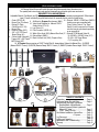
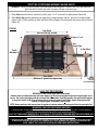
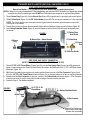
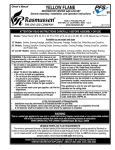
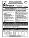
Owner’s Manual
Flaming Ember Burner
General Assembly, Installation, and Operation Instructions.
If using the “ EASY” Safety Pilot System consult separately attached instructions.
Register Your Purchase at www.rasmussen.biz.
®
THE GAS LOG COMPANY
12028 E. PHILADELPHIA ST.
WHITTIER, CA 90601 U.S.A.
www.rasmussen.biz
Report # 10-38
REV: FEB 0410
Last Printed: 4/27/2010 3:42 PM
ATTENTION! READ INSTRUCTIONS CAREFULLY BEFORE ASSEMBLY OR USE
For use with Vented Hearth Kits, Natural Gas Burners; F, FH, FX, FXH, or Propane Gas Burners; FA, FAH, FAX, FAXH
INSTALLER: Leave this manual with the appliance.
WARNING: If the information in this manual is not
followed exactly, a fire or explosion may result caus- CONSUMER: Retain this manual for future reference.
ing property damage, personal injury or loss of life.
Improper installation, alteration, service or
— Do not store or use gasoline or other flammable
maintenance can cause property damage, personal
vapors and liquids in the vicinity of this or any other
injury or loss of life. Read these instructions
appliance.
thoroughly before installation. For assistance or
additional information, consult your gas log dealer,
— WHAT TO DO IF YOU SMELL GAS
qualified installer, service agency or gas supplier.
• Do not try to light any appliance.
• Do not touch any electrical switch; do not use
This appliance may be installed in an aftermarket,
any phone in your building.
permanently located, manufactured (mobile) home,
• Immediately call your gas supplier from a
where not prohibited by local codes.
neighbor’s phone. Follow the gas supplier’s
instructions.
This appliance is only for use with type of gas
• If you cannot reach your gas supplier, call the fire indicated on the rating plate.
department.
Installation must conform with local codes or, in the
— Installation and service must be performed by a
absence of local codes, with the National Fuel Gas
qualified installer, service agency or the gas
Code, ANSI Z223.1/NFPA 54.
supplier.
•
•
•
In the Commonwealth of Massachusetts:
Installation must be performed by a licensed plumber or gas fitter.
The chimney flue damper, when used with gas logs, will be welded open or completely removed.
A CO detector shall be installed in the room where the appliance is installed.
IMPORTANT INFORMATION
This burner and gas log set are for use in a fully functioning wood burning fireplace with the DAMPER WIDE OPEN,
it must be installed in a FULLY VENTED solid-fuel burning fireplace with a working flue constructed of non
combustible material. The FLUE MUST VENT ALL PRODUCTS OF COMBUSTION.
CARBON MONOXIDE POISONING MAY LEAD TO DEATH
When used without fresh air, decorative gas appliances may give off carbon monoxide, an odorless, colorless,
poisonous gas. Some people, pregnant women, persons with heart or lung disease, anemia, persons under the
influence of alcohol and persons who live at high altitudes are more affected by carbon monoxide than others.
Early signs of carbon monoxide poisoning resemble the flu and include; headache, dizziness and/or nausea. If
you have these symptoms, the burner or the appliance may not be installed or working properly, or the flue may
be blocked. GET FRESH AIR AT ONCE! Verify that the gas log set is properly arranged and have the heater and
chimney flue serviced before using again.
WARNING:
A SAFETY PILOT MUST BE INSTALLED ON ALL UNITS DESIGNED OR CONVERTED TO BURN PROPANE GAS
Compliant with The Department of Building and Safety, Rule of General Application No. RGA2-72, “Standard for
decorative Log Sets for Installation in Wood Burning Fireplaces” Decorative Gas Appliances for Installation in
Solid-Fuel Burning fireplaces.
The installation and the provisions for combustion and ventilation air must conform with The National Fuel Gas
Code ANSI Z223.1 / NFPA54, or The CSA B149.1, Natural Gas and Propane Installation Code, latest edition.
1
IMPORTANT INFORMATION
• Due to high temperatures, the appliance should be located out of traffic and away from furniture and draperies.
• Children and adults should be alerted to the hazard of high surface temperatures and should stay away to avoid burns or
clothing ignition.
• Young children should be carefully supervised when they are in the same room with the appliance.
• Do not place clothing or other flammable material on or near the appliance.
• Any safety screen or guard removed for servicing an appliance must be replaced prior to operating the appliance.
• Installation and repair should be done by a qualified service person. The appliance should be inspected before use and at
least annually by a professional service person. More frequent cleaning may be required due to excessive lint from
carpeting, bedding material etc. It is imperative that control compartments, burners and circulating air passageways of the
appliance be kept clean.
• WARNING: Any change to this appliance or its controls can be dangerous.
• WARNING: Failure to keep the primary air opening(s) of the burner clean may result in sooting and property damage.
• Keep appliance area clear and free from combustible materials, gasoline and other flammable vapors and liquids.
• DO NOT use this room appliance if any part has been under water. Immediately call a qualified service technician to inspect the appliance and to replace any part of the control system and any gas control that has been under water.
• WARNING: Before installing in a solid-fuel burning fireplace, the chimney flue and firebox must be cleaned of soot,
creosote, ashes and loose paint by a qualified chimney cleaner.
• WARNING: Do not allow fans to blow directly into the fireplace. Avoid any drafts that alter burner flame patterns.
• WARNING: Do not use a blower insert, heat exchanger insert or any other accessory not approved for use with this heater.
• A fireplace screen must be in place when the appliance is operating and, unless other provisions for combustion air are
provided, the screen shall have an opening(s) for introduction of combustion air.
• Solid fuels shall not be burned in a fireplace where this appliance is installed.
• WARNING: Glass doors must be fully opened when appliance is in operation to allow for safe combustion, cooling of
components and venting.
• Any outside air ducts and/or ash dumps in the fireplace shall be permanently closed at the time of appliance installation.
• This appliance may be used in bedrooms and bathrooms if used in a vented application, subject to local codes.
• Avoid contact with the objects, chassis or another part which may be hot during operation.
This product is designed to be an ATTENDED appliance. Do not leave this unit burning while unattended or
while anyone is sleeping. Young children MUST be supervised when in the same room with the appliance and
are NOT to operate this unit.
WARNING! CHECK FOR PROPER VENTING
A properly sized, unobstructed chimney will normally vent all products of combustion. Any odor or smoke detected
inside the room is an indication that the flue is not functioning properly.
SHUT OFF THE BURNER IMMEDIATLEY! THE CAUSE OF THE VENTING PROBLEM MUST BE DISCOVERED
AND CORRECTED BEFORE CONTINUED USE OF THE GAS LOG SET.
Continued use with improper venting may cause damage to your fireplace, room furnishings and could cause serious illness.
IF IMPROPER VENTING IS SUSPECTED, IMMEDIATELY HAVE BURNER AND CHIMNEY FLUE SERVICED.
ALSO, VERIFY THAT LOG SET IS INSTALLED PER THESE INSTRUCTIONS.
MINIMUM AND MAXIMUM INLET GAS SUPPLY PRESSURES
The minimum inlet gas supply pressure shall be 6 inches of water column on Natural Gas and 11 inches of water
column on Propane. The maximum inlet gas supply pressure shall be 7 inches of water column on Natural Gas and
14 inches of water column on Propane. The appliance and its main gas valve must be disconnected from the gas
supply piping system during pressure testing of that system at test pressures in excess of 1/2 psi (3.5 kPa).
The appliance must be isolated from the gas piping system by closing its equipment shutoff valve during any
pressure testing of the gas supply piping system at test pressures equal to or less than 1/2 psi (3.5 kPa).
WARNING—Proposition 65 Statement
If not installed, operated and maintained in accordance with these instructions, this product could expose you
to substances in fuel or from fuel combustion which are known to the State of California to cause cancer,
birth defects or other reproductive harm.
2
PARTS LIST
(Parts not shown to scale)
All Flaming Ember Burners will include the parts listed below except where otherwise noted.
The quantity and/or size of parts and supplies shown will vary with each style burner and control.
REQUIRED TOOLS AND MATERIALS
Adjustable Wrench, Pipe Wrench and Pipe Sealing compound (required if fittings not already pre-wrapped with Teflon thread
tape). Consult individually supplied instructions for assembly and/or parts not listed below.
1. Grate (HFG15-48)
9. Air Mixer for Propane Gas burners (MA2) 16. Optional -SPK3E, -RPK3E and -RMC1E
2. Burner Pan (FX shown) 10. Valve Knob Extender for Manual “EASY
models come pre-assembled with
3. Rating/I.D. Plate
“Easy” Safety Control. The “Easy”
Safety Valve (STV-10)
4. Orifice Spud (01-XX)
Safety Control is required for Propane
11. Log Lifters (LL)
5. Burner Plug
sets and may be purchased separately
6. Damper Clamp (DC1) 12. Flex Connector (SSCB-14)
as an upgrade kit.
7. 3/8” x 1/2” FIP Flared 13. White Silica Sand (SS8) (Natural Gas Sets) 17. Optional V17B Manual Valve Kit
Brass Fitting (A1)
14. Ember Magic (EMX1)
A) 3/8” MIP x 3/8” MIP Valve (V17)
8. Orifice Holder (Internally
15.
Black
Volcanic
Ash
(VA5)
(Propane
Sets)
B) 3/8” x 3/8” Street Elbow
Tapped 3/8” x 3/8” Flared
C) 9” long Key (K5)
MIP Fitting) (A2T)
18. All Propane Burners require an “EASY” Safety Pilot Kit, shown below. Optional for Natural Gas. A) SPK3E
(Manual “EASY” Control), B) RPK3E (Remote Ready “EASY” Control), C) RMC1E (Variable Flame Height “EASY” Control)
3
2
1
4
6
7
12
11
9
5
10
8
14
13
A.
15
B.
C.
Optional V17B Manual Valve
assembly (see Pg 5 also)
16
17
18
A.
B.
C
3
TABLE OF CONTENTS
Preparation……………………………………..Page 4
Positioning Burner Pan and Grate…………… Page 5
Assembly and Gas Supply Connection
●
Standard Match Lighted Models……...…. Page 6
• Optional Accessory Match Lighted with
Manual V17 Valve……………………….. Page 7
• “EASY” Safety Pilot Kits………………… Page 9
Pan Medium Installation ● Natural Gas……… Page 10
● Propane……......... Page 11
Log Placement………………………………… Page 13
Lighting and Operation……………………….. Page 14
Maintenance and Troubleshooting…………... Page 15
Warranty……………………………………….. Page 16
GENERAL INSTALLATION INSTRUCTIONS
WARNING: Failure to position the parts in accordance with these diagrams or failure to use only parts specifically
approved with this appliance may result in property damage or personal injury.
MINIMUM FIREPLACE REQUIRMENTS
The Minimum permanent chimney or damper opening is the minimum permanent free opening required by Standards or Codes
to ensure safe operation of the appliance and must be at least 39 square inches for 18”-20” models, 51 square inches on 24”
models and 64” on 30” models based on a minimum chimney height of 10 feet. It is NOT the minimum operating damper position.
Log Set
Size
Opening
Height
Firebox
Depth
18"
20"
24"
30"
16"
16"
16"
16"
13"
13"
13"
13"
Front
Firebox
Width
24"
26"
30"
36"
Rear
Firebox
Width
18"
20"
24"
30"
Chimney
Diameter
Min. Permanent
Chimney Opening
7"
7"
7"
8"
39 Sq in.
39 Sq in.
51 Sq in.
64 Sq in.
Btu/Hour - Max. Input
Natural
Propane
Gas
Gas
43,000
27,000
56,000
35,000
72,000
37,000
75,000
50,000
(Residents of the Commonwealth of Massachusetts please consult
note on page 1 regarding installation before continuing.)
STEP ONE PREPARATION:
1. Verify that the Valve Assembly is correctly matched to the log set,
burner, and gas supply.
2. Turn off Fireplace Gas Supply (Figure 1A) .
3. Thoroughly clean fireplace floor of any ashes and have a qualified
chimney cleaner insure that the chimney flue and firebox are free of
soot, creosote, and loose paint.
4. Attach Damper Clamp (Figure 2A) over edge of fireplace Damper
Blade (Figure 2B) to prevent damper from closing accidentally. If
unable to attach damper clamp, drill a hole (or holes) in the damper
or remove it completely.
FIGURE 1
Log Lighter
Valve Assembly (V1)
FIGURE 2
A) Fireplace Gas
Supply Valve
B) Damper
Blade
Minimum Opening
Height 16”
Gas Supply
Pipe
A) Damper
Clamp
C) Aprox. 1” from
front leg of grate
Grate
Burner Pan
IMPORTANT GUIDELINES
•
•
•
•
•
•
•
•
The chimney damper must be wide open and fixed in a manner to maintain a permanent free opening at all
times as outlined above.
The area of the flue must be not less than 1/10 the area of the fireplace opening.
This gas log set must be installed in fully VENTED metal or masonry fireplace with a working flue that is safe for burning a
wood fire.
The flue must be free of any obstructions and must exhaust all products of combustion.
At least 12” of noncombustible or heat resistant material is required above the fireplace. A fireplace hood will be
required to act as a heat deflector in protecting combustible fireplace surrounds (facing and/or mantel) if certain
minimum clearances cannot be met.
Be certain that combustible flooring material (i.e. carpet, tile etc.) is not too close to this gas appliance. If this appliance is at floor level or less than 6” above the floor, there must be at least 12” of noncombustible material between
the base of the fireplace and any combustible flooring.
Input ratings shown in BTU per hour are for elevations up to 2,000 ft. For elevations above 2,000 ft. refer to the
National Fuel Gas Code, or visit www.nfpa.org.
The Gas appliance and it’s main gas valve must be disconnected from the gas supply piping system during any
pressure testing of that system as required by NFPA 54.
4
STEP TWO: POSITIONING BURNER PAN AND GRATE
WARNING: Failure to position the parts in accordance with these diagrams or failure to use only parts specifically
approved with this heater may result in property damage or personal injury.
1. Place Grate inside the firebox, centered from left to right, 0” to 2” of rear wall, as depth permits (Figure 3B).
2. Place Burner Pan beneath grate with open edge facing out approximately one inch forward of front legs of grate.
(Figure 2 and 3C) Mark positions of Grate and Burner Pan on fireplace floor with pencil then remove from the firebox
(Figure 3D).
FIGURE 3
Rear Width
(Not less than log set size)
B) Approx. 0” to 2”
Gas
Supply Pipe
V1 Gas Valve
Depth
Minimum 13”
C) Burner Pan
D)
Front Width
(Minimum 6” greater than log set size)
Long Valve
Key (K2)
(sold separately)
LEAK TEST PROCEDURES
WARNING: DO NOT use an open flame to test leaks!
Create a mixture of equal parts soap and water. Apply to all the joints of the pipe fittings from the gas supply to the
burner. Turn on the gas supply valve for no longer than 3-5 seconds. If bubbles appear in the soap solution applied
to the joints, there is a leak. Turn off the gas supply valve and tighten those fittings. Repeat the procedure until
bubbles no longer appear. Remember to test all joints.
NOTE: Always perform a leak test any time the appliance has been moved or disconnected from the gas supply line.
WARNING! CHECK FOR PROPER VENTING
A properly sized, unobstructed chimney will normally vent all products of combustion. Any odor or smoke detected
inside the room is an indication that the flue is not functioning properly.
SHUT OFF THE BURNER IMMEDIATELY! THE CAUSE OF THE VENTING PROBLEM MUST BE DISCOVERED AND
CORRECTED BEFORE CONTINUED USE OF THE GAS LOG SET.
Continued use with improper venting may cause damage to your fireplace, room furnishings and could cause serious illness.
IF IMPROPER VENTING IS SUSPECTED, IMMEDIATELY HAVE BURNER AND CHIMNEY FLUE SERVICED.
ALSO, VERIFY THAT LOG SET IS INSTALLED PER THESE INSTRUCTIONS.
5
STANDARD MATCH LIGHTED (NATURAL GAS MODELS ONLY)
STEP THREE: BURNER PAN ASSEMBLY
Natural Gas Models; F, FH, FX and FXH (All other Models refer to supplied instructions)
NOTE: If fittings do not come pre-wrapped with Teflon threaded tape, pipe compound MUST be applied to all tapered pipe threads
(except in #3 of Step 3) to prevent gas leaks. DO NOT use Teflon tape or pipe compound on any flared fitting threads.
1. Thread Burner Plug (Figure 4A.) into the Burner Pipe (Figure 4B) at opposite end of gas supply and wrench tighten.
2. Thread Orifice Spud (Figure 4C) into 3/8” Orifice Holder (Figure 4D) (Do not use pipe compound or Teflon tape here)
NOTE: The Orifice Spud is a gas consumption limiter. Higher flames (and greater gas consumption) may result if
orifice spud is not installed.
3. Thread Orifice Holder into Burner Pipe and wrench tighten with the flared end facing rear wall of firebox (Figure 4E).
4. Insert Rating Plate/Heat Shield (Figure 4F) onto the threads of and the Burner Pipe with labels facing away from
the burner.
F) Rating Plate/
FIGURE 4
Heat Shield
B) Burner Pipe Ember Burners
A) Burner
Plug
C) Orifice Spud
E) Flared
End
D) 3/8 Orifice Holder
STEP FOUR: GAS SUPPLY CONNECTION
(NOTE: ENSURE THAT GAS SUPPLY TO FIREPLACE IS OFF)
1. Thread 1/2” FIP x 3/8” Flared Elbow (Figures 5and 6A) onto the Gas Supply Pipe (Figures 5 and 6B) and wrench
tighten. If space between Gas Supply Pipe and Firebox floor allows, the flared end of the 1/2” FIP x 3/8”Elbow should
face down. (Figure 6A)
2. With Burner Pan inside firebox at previously marked position thread one end of the Flex Connector (Figures 5 and
6C) to the 1/2” FIP x 3/8” Flared Elbow and wrench tighten. Do not use pipe compound or tape on any flared threads.
3. Carefully bend the Flex Connector into position, connect to the Orifice holder and wrench tighten. If Flex Connector
is bent into too small of a radius it may kink or break causing air flow noise and/or gas leaks.
4. Proceed to Page 11 “Pan Medium Installation”
A) 1/2’ FIP X 3/8
Flared Elbow
FIGURE 5
Side View
Rating Plate/Heat Shield
B) Gas Supply
Pipe
C) Flex Connector
● Keep the Flex Connector as
close to bottom inside edge
of firebox floor as possible
6
STEP FOUR: GAS SUPPLY CONNECTION FOR STANDARD MATCH LIGHTED (Cont’d)
FIGURE 6
C) Flex Connector
D) Orifice Holder
B) Gas Supply Pipe
V1 Gas Supply
Valve
Burner Plug
A) 1/2’ FIP X 3/8”
Flared Elbow
(FX18 Burner Pan used for example)
OPTIONAL ACCESSORY MATCH LIGHTED WITH MANUAL “V-17” VALVE
(NATURAL GAS MODELS ONLY)
STEP THREE: BURNER PAN ASSEMBLY
NOTE: If fittings do not come pre-wrapped with Teflon threaded tape, pipe compound MUST be applied to all tapered pipe
threads (except in #3 of Step 3) to prevent gas leaks. DO NOT use Teflon tape or pipe compound on any flared fitting threads.
1. Thread Burner Plug (Figure 7A.) into the Burner Pipe at opposite end of gas supply (Figure 7B) and wrench tighten.
(If not already installed at Factory)
2. Thread 3/8” Street Elbow (Figure 7C) into Burner Pipe and wrench tighten into position shown.
3. Thread Orifice Spud (Figure 7D) (Without using pipe compound or Teflon tape) into 3/8” V-17 Valve (Figure 7E),
then thread Valve into 3/8” Elbow and wrench tighten into position shown.
NOTE: The Orifice Spud is a gas consumption limiter. Higher flames (and greater gas consumption) may result if
orifice spud is not installed.
4. Insert Rating Plate/Heat Shield (Figure 7F) between the burner pipe and the 3/8” Street Elbow.
5. Insert Key Sleeve (Figure 7G) over V-17 Valve Stem (7I)
FIGURE 7
A) Burner Plug
Apply pipe compound
If not pre-wrapped
with Teflon Tape
B) Burner Pipe
Ember Burners
E) 3/8” V-17 Valve
G) Key Sleeve
I) Valve Stem
D) Orifice Spud
(no tape or compound here)
C) 3/8” Street Elbow
F) Rating Plate / Heat Shield
7
ACCESSORY MATCH LIGHTED WITH MANUAL “V-17” VALVE (NATURAL GAS MODELS ONLY)
STEP FOUR: GAS SUPPLY CONNECTION
(ENSURE THAT GAS SUPPLY TO FIREPLACE IS OFF)
NOTE: If fittings do not come pre-wrapped with Teflon threaded tape, pipe compound MUST be applied to all tapered pipe
threads (except in #3 of Step 3) to prevent gas leaks. DO NOT use Teflon tape or pipe compound on any flared fitting threads.
1. Thread 1/2” FIP x 3/8” Flared Elbow (Figures 8 and 9A) onto the Gas Supply Pipe (Figures 8 and 9B) and wrench
tighten. If space between Gas Supply Pipe and Firebox floor allows, the flared end of the 1/2” FIP x 3/8”Elbow should
face down. (Figure 9A)
2. With Burner Pan inside firebox at previously marked position thread one end of the Flex Connector (Figures 8 and
9C) to the 1/2” FIP x 3/8” Flared Elbow and wrench tighten. Do not use pipe compound or tape on any flared
threads.
3. Attach Flex connector to the tapered end of the V17 valve (Figure 9D). Remember, If Flex Connector is bent into too small
of a radius it may kink or break causing air flow noise and/or gas leaks.
4. Proceed to Page12 “Pan Medium Installation”)
FIGURE 8
C) Flex Connector
Manual V-17 Valve
A) 1/2’ FIP X 3/8
Flared Elbow
B) Gas Supply Pipe
(F30 Burner Pan used here for example)
FIGURE 9
Side View
A) 1/2’ FIP X 3/8” Flared Elbow
Manual V-17 Valve
D) Tapered end
B) Gas Supply Pipe
Rating Plate / Heat Shield
•
C) Flex Connector
8
Keep the Flex Connector as close to
bottom inside edge of firebox floor
as possible
WARNING:
AN “EASY” SAFETY PILOT MUST BE INSTALLED ON ALL UNITS DESIGNED OR CONVERTED TO BURN PROPANE
GAS. THE “EASY” SAFETY PILOT CONTROL SYSTEM IS OPTIONAL FOR NATURAL GAS UNITS.
If utilizing the “EASY” Safety Pilot System with your Flaming Ember Burner use the individually
supplied instructions in conjunction with this instruction manual.
SPK3E
Manual Safety Pilot Control
The Manual Safety Pilot Control (standing pilot) provides safety shutdown in
the event of an interruption of the gas supply or flameout. It also provides a
convenient means of lighting the burner and controlling flame height. A safety
control is required for all propane installations, advisable for natural gas, and
is required for certain jurisdictions. "EASY" control allows for upgrade to remote operation at a later time. Refer to individually supplied instructions.
RMC1E
Wireless Variable Flame Height Remote Safety Pilot "EASY" Control.
Light the burner and adjust the flame height with the
hand-held wireless remote transmitter. Provides safety
shutdown in the event of an interruption in the gas supply
or flameout. It also provides a convenient means of
lighting the main burner. A safety control is required for
all Propane installations, is advisable for natural gas, and
is required in certain jurisdictions. (Comes with Variable
Flame Height Remote Control Transmitter, and Remote
Receiver). Refer to individually supplied instructions.
RPK3E
Remote Ready Safety Pilot "EASY" Control.
Requires one of the Wireless Remoter Transmitter Devices (below) to light the main burner. Adjust the
flame height manually by turning the knob at the valve. Provides safety shutdown in the event of an
interruption in the gas supply or flameout. Also provides a convenient means of lighting the main
burner. A safety control is required for all Propane installations, is advisable for natural gas, and is required in certain jurisdictions. The RPK3E Model comes with the Remote Receiver shown below left and
may be controlled by any one of the five Wireless Remote Transmitter Devices shown here (each sold separately) Refer to individually supplied instructions.
Wireless
Wireless
On/Off Remote
On/Off Remote with Thermostat
(SR-2R)
(THR-2R)
9
Wireless Wall Timer Wireless Wall
Switch
(Up to 120 Minutes)
(WS-2R)
(WT-2R)
Wireless Wall
Thermostat
(TS-2R)
STEP FIVE: PAN MEDIUM (NATURAL GAS MODELS)
If using a Natural Gas model, the Pan Medium is White Sand. Volcanic Ash may only be used as dressing for the
firebox floor (Figure 14). Volcanic ash is recommended for the pan filler for outdoor installation of the burner.
1. Completely cover Burner Pipe and Ember Boosters (if applicable) with Pan Medium (Figure 10) Starting from rear
of Burner Pan and moving toward leading edge. Use entire contents of bag provided, allowing medium to spill over
leading edge of burner pan (Figure 11). (Amount supplied will vary with each style burner)
FIGURE 10
A)
FIGURE 11
White Sand
Burner Pipe
Leading Edge
of Burner Pan
Ember Boosters
2. Sprinkle a light covering of “ Ember Magic” over the Pan Medium (Figure 10 below). Pull apart “Ember Magic” fiber
material into small, loose pieces to enhance the glowing ember effect. Spread remaining “Ember Magic” around ends
of pan to add to the ember bed appearance. When done the Burner Pan should look somewhat like the illustration
below.
FIGURE 12
WARNING: Wash hands after handling “Ember Magic” as it may cause skin irritation. When pouring Pan Medium
(White Sand) into burner pan do so slowly as it may stir up dust particles. Careful not to breath in dust.
10
STEP FIVE: PAN MEDIUM (PROPANE MODELS)
If using a Propane burner, the Pan Medium used will be Volcanic Ash (Amount supplied will vary with each style
burner). NEVER use White Sand inside a propane burner pan.
1. Completely cover Burner Pipe and Ember Boosters with the provided Black Volcanic ash (Figure 13) Starting from
rear of Burner Pan and moving toward leading edge. Use entire contents of bag provided, allowing medium to spill
over leading edge of burner pan (Figure 14A).
FIGURE 13
FIGURE 14
Black Volcanic
Ash
Burner Pipe
Leading Edge
of Burner Pan
Ember Boosters
A)
2. Sprinkle a light covering of “ Ember Magic” over the Black Volcanic Ash. Pull apart “Ember Magic” fiber material
into small, loose pieces to enhance the glowing ember effect. Spread remaining “Ember Magic” around ends of pan
to add to the ember bed appearance. When done the Burner Pan should look somewhat like the illustration below.
FIGURE 15
WARNING: Wash hands after handling “Ember Magic” as it may cause skin irritation.
11
WARNING: Failure to position the parts in accordance with these diagrams or failure to use only parts specifically
approved with this heater may result in property damage or personal injury.
FIGURE 16
Natural Gas burner shown with Optional Manual V17 Valve (Figure 16A) and Volcanic Ash (Figure 16B) sprinkled around
the outside of the Burner Pan for a decorative effect. Volcanic Ash may also be used to conceal the Flex Connector
(Figure 16C).
B) Volcanic Ash
Ember Magic over White Sand
A) Manual V17 Valve
C) Flex Connector hidden
under Volcanic Ash
FIGURE 17
Propane model shown with Optional SPK3E Control (Figure 17A), Volcanic Ash used inside the Burner Pan as pan
medium and sprinkled around the outside of the Burner Pan for a decorative effect. Volcanic Ash may also be used to
conceal the Flex Connector (as in Figure 15C above) but DO NOT obstruct air mixer holes.
A)
12
STEP 6: LOG PLACEMENT
CAUTION: Crowded logs will cause poor combustion and result in excessive soot formation.
Depending on the log style and size, log sets contain from 6 to 10 individual logs and sometimes pine cones. The largest logs
will be the Front and Rear Logs. Some log sets have two separate front logs which simulate a charred/burnt effect between the
two halves. (Figure 18) Place the Longest Log (or 2 largest “charred” logs if applicable) as far forward on the Grate as possible.
The next Longest Log is placed as far to the rear as possible on top of optional Log lifters (Figure 18A) (if provided). The remaining logs, or “Top Logs” are placed diagonally across the Front and Rear logs with the larger top logs placed first allowing
flame to pass freely between them. Several examples are provided below with the Burner Pan and Valve omitted for clarity.
FIGURE 18
Side View of 18” Lone Star log set
Large Top
Log
Front
Log
FIGURE 19
Front View of 24” Crossfire log set
Small Top
Log
Small Top Logs
Large Top Log
Large Top Log
Rear
Log
A)
Log
Lifters
Front Log
FIGURE 21
Top View of 24” Evening Crossfire log set
FIGURE 20
Top View of 18” Lone Star log set
Large Top
Log
Small Top
Rear Log
Log
Small Top Logs
Small Top
Log
Rear Log
Large Top
Log
Large Top
Log
Front Log
A) Two Front Charred Logs
DAMPER AND GLASS DOORS MUST BE FULLY OPEN BEFORE LIGHTING OR BURNING FOR PROPER
VENTILATION AND TO PREVENT HEAT DAMAGE TO THE VALVE.
IMPORTANT: YOUR GAS LOG SET SHOULD BE OPERATED FOR THE FIRST 2-3 HOURS AT A LOW FLAME
SETTING TO ALLOW TEMPERING OF THE REFRACTORY LOGS.
13
FIGURE 22
Fully Assembled Evening Crossfire Log Set shown with Optional Manual V17 Valve.
STEP SEVEN: LIGHTING AND OPERATION INSTRUCTIONS
WARNING: Failure to position the parts in accordance with these diagrams or failure to use only parts specifically
approved with this appliance may result in property damage or personal injury.
Applies to Natural Gas Models F, FH, FX, FXH. All other models refer to supplied instructions.
BEFORE LIGHTING: Smell around the burner area and next to floor for gas. Propane gas is heavier than air and may
settle on the floor. If you smell gas follow the instructions on page 1.
•
STANDARD MATCH LIGHTING
1. Place lighted match on embers near inlet end of burner (Figure 23 ).
DO NOT HOLD MATCH IN HAND! Move away from front of fireplace.
2. Slowly open Fireplace Gas Supply Valve and wait for burner to light.
3. Adjust Fireplace Gas Supply Valve for desired flame height.
4. To shutdown close Fireplace Gas Supply Valve completely.
•
Cut away View
Showing Inlet Side of Burner
under Pan Medium and Ember Magic
MATCH LIGHTING WITH OPTIONAL ACCESSORY V-17 VALVE
1. Ensure that the Manual V-17 Valve is completely closed.
2. Open Fireplace Gas Supply Valve.
3. Place lighted match on embers near inlet end of burner (Figure 23)
DO NOT HOLD MATCH IN HAND! Move away from front of fireplace.
4. Slowly open Manual V-17 Valve and wait for burner to light.
5. Adjust Fireplace Manual V-17 Valve for desired flame height.
6. To shutdown close both Manual V-17 Valve and Fireplace Gas Supply
Valve completely.
14
FIGURE 20
•
•
•
PROPER MAINTANANCE
Keep the area around the log set clean and clear of debris.
When logs develop soot, turn burner on for 15 minutes then lightly spray soot areas with water. Soot will then evaporate.
Periodically examine and clean the venting system. Once every year, a qualified agency or certified chimney sweep should
examine and clean the venting system of the solid fuel burning fireplace in which the log set is installed.
APPLIANCE BREAK-IN
During the 2-3 hour appliance break-in period, you may detect an odor from the appliance as the various water- based paints used
in the manufacture of this log set cure. This is normal and temporary situation that is not a cause for alarm. However, you may want
to provide extra ventilation to the room during this time.
To ensure proper curing of the logs:
1) Ignite a 2” flame and maintain it for 1/2 hour.
2) Burn the logs in consecutive 1/2 hour periods, raising the flame an additional 2” to full flame height for a total of three hours.
TROUBLE SHOOTING
Log Set is Smoking/Sooting Excessively
It is natural and unavoidable for vented log sets to produce moderate levels of carbon (soot) where flame contacts the logs. However, if soot is produced where there is no flame impingement, one of the following may be the cause;
Fireplace venting system not drafting properly: Make sure the damper is wide open at all times. Preheat the flue in very cold
weather by burning the log set at very low level, then slowly increasing the flame height over a matter of hours. Have the fireplace
and the venting system professionally cleaned.
Excessive flame impingement or blockage: Make sure there is proper spacing between the logs so they are not smothering the
flame. Rearrange the logs so they are touched less by the flames.
Excessive gas supply/pressure: Make sure the gas pressure coming into the fireplace does not exceed the maximum pressure
allowed with this gas set (refer to page 2). If you are using the gas logs with an “EASY” Safety Pilot Kit, make sure you installed the
correct orifice into the set.
Burner is Excessively Noisy
Please Note: The movement and combustion of gas will create low, unavoidable levels of noise.
Excessive gas pressure: Make sure the gas pressure coming into the fireplace does not exceed the maximum
pressure allowed with this gas set (refer to page 2). If you are using the gas logs with an “EASY” Safety Pilot Kit, make sure you
installed the correct orifice into the set.
Passage of air/gas across irregular surfaces: There may be burrs, paint or other blockages on the burner bar ports. Check
these ports and remove any blockage.
Gas Connector: Relieve any tight bends or kinks in the Flex Connector or switch to a smooth aluminum or copper connector, which
can be purchased at hardware or home improvement stores. Do not use Flex Connectors other than those supplied by Rasmussen.
Burner Flame is Too High (8-12” Above Top Logs) or Too Low (Below Top Logs)
Incorrect gas supply, pressure, or burner orifice used: Make sure the gas pressure coming into the fireplace falls between the
minimum and maximum pressures allowed with this gas set (refer to page 2). If you are using the gas logs with a safety pilot kit,
make sure you installed the correct orifice.
Blocked ports (low flame only): Free the main burner orifice and burner bar ports of any burrs, paint or other blockage.
SERVICE AND TROUBLESHOOTING GUIDE FOR MODELS USING THE “EASY” SAFETY PILOT KIT
Analysis and correction of control of service problems must be made by qualified gas service technicians only. Attempts to service
or repair the “EASY” Safety Pilot Kit by other than authorized service personnel will void the manufacture’s warranty. In general ,
failure of “EASY” Safety Pilot Control may be due to the reasons noted below:
1. Pilot will not light initially:
● Check for loose Thermocouple terminal nut connection. Finger tip tighten plus 1/4 turn with wrench.
● Check for improper pilot flame adjustment.
● Check that Valve Knob is fully depressed during pilot lighting operation and held depressed for 30 to 60 seconds.
● Check for defective Thermocouple.
● Check for defective thermo magnet unit.
2. Pilot / Main burner clicks off after 5 to 30 minutes of burning:
● Valve and Thermocouple are not defective, otherwise pilot would not initially light.
● Thermocouple loses temperature difference between hot tip and cold junction (base).
● Check that only tip of Thermocouple is in main burner flame.
● Remove then replace logs to alter heat radiation pattern. Ensure that glass doors are open.
● Ensure that proper size gas log set is installed. Too large of a set decreases cooling air flow.
15
LIMITED LIFETIME CONSUMER PRODUCT WARRANTY
The following warranty has been drafted to comply with the MAGNUSON-MOSS WARRANTY ACT applicable
to products manufactured after July 4, 1975, It replaces and supersedes any warranty in this package or in any printed literature.
EXCLUSIONS FROM WARRANTY:
LIMITED WARRANTY:
(1)
The
foregoing
warranty is limited solely as set forth herein and
RASMUSSEN IRON WORKS INC, 12028 E. Philadelphia Street, Whitapplies only for the designated above.
tier California, U.S.A., warrants this Gas Log Set and accessories
against defects in materials and workmanship, and suitable for a
(2) RASMUSSEN shall not be liable for any loss, damage incidental
particular purpose, for a period of:
or consequential damages of any kind, whether based upon
warranty, contract, or negligence, arising in connection with the
Home (Non-Commercial use):
sale, use or repair of the product. Some states do not allow the
(1) LOG CASTINGS - All logs are guaranteed against crumbling in
exclusion or limitation of incidental or consequential damages, so
the original installation for the lifetime of the initial purchaser.
the above limitation or exclusion may not apply to you.
(2) BURNERS/GRATES - 2 Years from date of purchase.
(3) The maximum liability of RASMUSSEN in connection with this
limited warranty shall not in any case exceed the contract price
(3) SAFETY CONTROLS - Pilots and Safety Controls are covered by
paid for the product claimed to be defective or unsuitable.
warranty of the original manufacturer only.
(4) This warranty does not extend to any product manufactured by
Commercial Use:
RASMUSSEN which has been subjected to misuse, neglect,
All components - 1 year from date of purchase
accident improper installation, or use in violation of instructions
furnished by RASMUSSEN.
THIS WARRANTY IS FOR THE BENEFIT OF THE ORIGINAL
(5) This warranty does not extend to or apply to any unit which has
PURCHASER.
been repaired or altered in any place other that RASMUSSEN
WARRANTY ADJUSTMENT:
IRON WORKS INC. factory, or by persons not expressly
(1) RASMUSSEN agrees to repair or furnish a replacement for, but
approved by RASMUSSEN.
not remove or install any product or component which proves
(6)
Components
manufactured by any supplier other than
defective within the above warranty and appropriate time
RASMUSSEN
shall bear only that warranty made by the
periods stated.
manufacturer of that product.
(2) BUYER notify RASMUSSEN of any defect within this warranty
(7) Freight damage, cracking from thermal shock, and color changes
no later than thirty (30) days after a defect is discovered.
occur from causes beyond manufacturer’s control and are not
(3) No product will be accepted for return or replacement without
covered by any warranty.
written authorization of RASMUSSEN. Before returning
merchandise, write to RASMUSSEN Giving us full details of the
complaint and a copy of the sales receipt or other evidence of
the purchase date. Merchandise returned without proof of
THIS WARRANTY GIVES YOU SPECIFIC LEGAL RIGHTS, AND YOU
purchase date will be serviced out-of-warranty at our prevailing
MAY ALSO HAVE OTHER RIGHTS WHICH VARY FROM STATE TO
service and parts rates. If merchandise was damaged in transit,
STATE.
the file claim must be addressed as follows:
RASMUSSEN IRON WORKS INC
12028 E. PHILADELPHIA STREET
WHITTIER, CALIFORNIA 90601
Shipping charges must be pre-paid by the buyer.
REPAIR OR REPLACMENT UNDER THIS WARRANTY WILL BE
SHIPPED FREIGHT COLLECT.
RASMUSSEN IRON WORKS, INC. shall be held harmless from
any and all claims by the buyer as a result of injury or damage to
an Ultimate user or other person caused by the product sold
herein by the seller to the buyer, whether the injury or damage
results from the assembly, product installation, operation, shipment, storage or manufacture of this product. RASMUSSEN IRON
WORKS, INC. makes no warranties, expressed or implied, other
than those expressly stated herein.
* CUSTOMER RESPONSIBILITY *
Your Gas Log is designed to burn with a natural smoky yellow flame that produces carbon soot. Like a wood fire,
burning a Gas Log with the flue blocked or closed will cause fumes and smoke to remain in the room and
cause health hazards.
DAMPER MUST BE FULLY OPEN WHEN BURNING A GAS LOG SET.
CONSUMER RECORD CARD
Please record and retain information for future reference. Register your product at www.rasmussen.biz
®
LOG MODEL:
SAFETY CONTROL:
DATE OF PURCHASE:
DEALER:
INSTALLER:
16