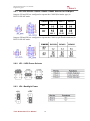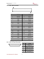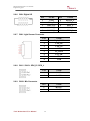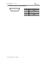
1
TA33 Motherboard 3.5” Fanless SBC with TI AM3354 Processor. User Manual / Engineering Spec. Version 1.1 FCC Statement This device complies with part 15 FCC rules. Operation is subject to the following two conditions: This device may not cause harmful interference. This device must accept any interference received including interference that may cause undesired operation. This equipment has been tested and found to comply with the limits for a class "a" digital device, pursuant to part 15 of the FCC rules. These limits are designed to provide reasonable protection against harmful interference when the equipment is operated in a commercial environment. This equipment generates, uses, and can radiate radio frequency energy and, if not installed and used in accordance with the instruction manual, may cause harmful interference to radio communications. Operation of this equipment in a residential area is likely to cause harmful interference in which case the user will be required to correct the interference at him own expense. TA33 Motherboard User Manual I TA33 Motherboard User Manual / Engineering Spec. Copyright Notice No part of this document may be reproduced, copied, translated, or transmitted in any form or by any means, electronic or mechanical, for any purpose, without the prior written permission of the original manufacturer. Trademark Acknowledgement Brand and product names are trademarks or registered trademarks of their respective owners. Disclaimer We reserve the right to make changes, without notice, to any product, including circuits and/or software described or contained in this manual in order to improve design and/or performance. We assume no responsibility or liability for the use of the described product(s), conveys no license or title under any patent, copyright, or masks work rights to these products, and makes no representations or warranties that these products are free from patent, copyright, or mask work right infringement, unless otherwise specified. Applications that are described in this manual are for illustration purposes only. Winmate Communication Inc. makes no representation or warranty that such application will be suitable for the specified use without further testing or modification. Warranty We warrant that each of its products will be free from material and workmanship defects for a period of one year from the invoice date. If the customer discovers a defect, We will, at its option, repair or replace the defective product at no charge to the customer, provided it is returned during the warranty period of one year, with transportation charges prepaid. The returned product must be properly packaged in its original packaging to obtain warranty service. If the serial number and the product shipping data differ by over 30 days, the in-warranty service will be made according to the shipping date. In the serial numbers the third and fourth two digits give the year of manufacture, and the fifth digit means the month (e. g., with A for October, B for November and C for December). For example, the serial number 1W11Axxxxxxxx means October of year 2011. TA33 Motherboard User Manual II TA33 Motherboard User Manual / Engineering Spec. Packing List Before using this Motherboard, please make sure that all the items listed below are present in your package: TA33 Motherboard User Manual If any of these items are missing or damaged, contact your distributor or sales representative immediately. Customer Service We provide service guide for any problem as follow steps: The first, contact with your distributor, sales representative, or our customer service center for technical support if you need additional assistance. You may have the following information ready before you call: Product serial number Peripheral attachments Software (OS, version, application software, etc.) Description of complete problem The exact wording of any error messages In addition, free technical support is available from our engineers every business day. We are always ready to give advice on application requirements or specific information on the installation and operation of any of our products. Please do not hesitate to call or e-mail us. TA33 Motherboard User Manual III TA33 Motherboard User Manual / Engineering Spec. Safety Precautions Warning! Always completely disconnect the power cord from your chassis whenever you work with the hardware. Do not make connections while the power is on. Sensitive electronic components can be damaged by sudden power surges. Only experienced electronic personnel should open the PC chassis. Caution! Always ground yourself to remove any static charge before touching the CPU card. Modern electronic devices are very sensitive to static electric charges. As a safety precaution, use a grounding wrist strap at all times. Place all electronic components in a static-dissipative surface or static-shielded bag when they are not in the chassis. TA33 Motherboard User Manual IV TA33 Motherboard User Manual / Engineering Spec. Safety and Warranty 1. 2. 3. 4. 5. 6. 7. 8. 9. 10. 11. 12. 13. 14. 15. Please read these safety instructions carefully. Please keep this user's manual for later reference. Please disconnect this equipment from any AC outlet before cleaning. Do not use liquid or spray detergents for cleaning. Use a damp cloth. For pluggable equipment, the power outlet must be installed near the equipment and must be easily accessible. Keep this equipment away from humidity. Put this equipment on a reliable surface during installation. Dropping it or letting it fall could cause damage. The openings on the enclosure are for air convection. Protect the equipment from overheating. DO NOT COVER THE OPENINGS. Make sure the voltage of the power source is correct before connecting the equipment to the power outlet. Position the power cord so that people cannot step on it. Do not place anything over the power cord. All cautions and warnings on the equipment should be noted. If the equipment is not used for a long time, disconnect it from the power source to avoid damage by transient over-voltage. Never pour any liquid into an opening. This could cause fire or electrical shock. Never open the equipment. For safety reasons, only qualified service personnel should open the equipment. If any of the following situations arises, get the equipment checked by service personnel: A. The power cord or plug is damaged. B. Liquid has penetrated into the equipment. C. The equipment has been exposed to moisture. D. The equipment does not work well, or you cannot get it to work according to the user’s manual. E. The equipment has been dropped and damaged. F. The equipment has obvious signs of breakage. Do not leave this equipment in an uncontrolled environment where the storage temperature is below -20° C (-4°F) or above 60° C (140° F). It may damage the equipment. TA33 Motherboard User Manual V TA33 Motherboard User Manual / Engineering Spec. Revision History Version Date 1.0 2013.7.24 First Release Karen Liu 1.1 2014.8.21 Update Seven Fan TA33 Motherboard User Manual Note VI Author TA33 Motherboard User Manual / Engineering Spec. Contents CHAPTER 1 1.1 1.2 1.3 1.4 1.5 CHAPTER 2 GENERAL INFORMATION .......................................2 INTRODUCTION ............................................................................... 2 FEATURE ......................................................................................... 2 MOTHERBOARD SPECIFICATIONS .................................................... 3 FUNCTION BLOCK ........................................................................... 4 BOARD DIMENSIONS........................................................................ 5 INSTALLATIONS.........................................................7 2.1 2.2 2.3 2.4 I/O EQUIPMENT INSTALLATION ....................................................... 7 12V DC-IN ..................................................................................... 7 SERIAL COM PORTS ........................................................................ 7 ETHERNET INTERFACE ..................................................................... 7 2.5 2.6 2.7 2.8 2.9 USB PORTS ..................................................................................... 7 AUDIO FUNCTION ............................................................................ 7 JUMPERS AND CONNECTORS ........................................................... 8 JUMPER SETTING............................................................................. 9 CONNECTORS AND PIN ASSIGNMENT ............................................ 12 TA33 Motherboard User Manual VII General Information CHAPTER TA33 Motherboard User Manual / Engineering Spec. 1 This chapter includes the TA33 Motherboard background information. Sections include: Introduction Feature Motherboard Specification Function Block Board Dimensions TA33 Motherboard User Manual 1 TA33 Motherboard User Manual / Engineering Spec. Chapter 1 General Information 1.1 Introduction TA33 SBC is an integrated package that provides customers a complete RISC platform for project evaluation, application development and solution feasibility testing that decreases lead-time and lowers initial cost and investment. In peripheral connectivity, TA33 SBC features with one LAN port which supports PoE (Power over Ethernet), six USB 2.0 connectors (two type A connector; four Pin Header ), three COM port (RS232/422/485 selectable; one D-Sub connector; two Pin Header), and one Micro SD card reader. 1.2 Feature 3.5” Form Factor ( 146mm x 101mm) Supports TI CortexTM – A8 AM3354 720MHz processor Android 4.1.2 / WinCE 7.0 / Linux supported LVDS interface supporting up to 1366x768 1 x micro SD/SDHC Card Slot Built-in NAND flash memory Power Over Ethernet (PoE) supported Optional CANbus support Optional Wifi support TA33 Motherboard User Manual 2 TA33 Motherboard User Manual / Engineering Spec. 1.3 Motherboard Specifications CPU Type CPU Speed LCD interface LAN Memory Type Built-in Storage Audio Edge Connectors On Board Pin-Header Connectors Dimensions Mechanical & environmental TI Cortex A8 AM3354 720MHz 720 MHz LVDS interface supporting up to 1366x768 1 x Giga LAN (supporting PoE function ) 512MB DDR2 SDRAM 533MHz 1GB Nand Flash 1 x Mic Input(2 pin) 2 x Stereo Speaker Out(2 pin) 1 x 2.5Ø DC Jack 1 x 9 Pin D-Sub CANbus PinOut (optional) 2 x USB A-type (Host) 1 x RS232/422/485 selectable 1 x RJ-45 10/100/1000 (Support PoE function) 1 x Micro SD Card Slot 1 x LVDS by pin-header (up to 1366x768) 1 x I2C Touch by pin-header 4 x USB by 2 pin-header (4 x 2 pin) 1 x RS232/422/485 by pin-header 1 x CANbus by pin-header (non-isolation) 1 x Digital I/O with 3.3V (8-pin GPIO) 1 x Reset by pin-header 146 mm x 101 mm (3.5" Form Factor) Operating temperature: -10 deg. C to 60 deg. C Operating Humidity: 10 ~ 90% Relative humidity, non-condensing TA33 Motherboard User Manual 3 TA33 Motherboard User Manual / Engineering Spec. 1.4 Function Block TA33 Motherboard User Manual 4 TA33 Motherboard User Manual / Engineering Spec. 1.5 Board dimensions TA33 Motherboard User Manual 5 CHAPTER TA33 Motherboard User Manual / Engineering Spec. Installation 2 This chapter provides information on how to use the jumpers and connectors on the TA33 Motherboard. The Sections include: I / O Equipment Installation Jumpers and Connectors Setting the Jumpers Connectors and Pin Assignment TA33 Motherboard User Manual 6 TA33 Motherboard User Manual / Engineering Spec. Chapter 2 Installations 2.1 I/O Equipment Installation 2.2 12V DC-IN The Motherboard allows plugging 12V DC-IN jack on the board without additional power module converter. 2.3 Serial COM ports There are two built-in COM port (RS232/422/485 selectable; one with 9-pin D-Sub and the other with pin-header) on TA33. When an optional touch-screen is ordered with PPC, serial com port can connect to a serial or an optional touch-screen. 2.4 Ethernet interface The Motherboard is equipped with one RJ-45 jack which is fully compliant with the PCI 10/100/1000 Mbps Ethernet protocol. The LAN port also supports PoE function (Power over Ethernet; 802.3AT). 2.5 USB ports Six USB devices (Four with pin headers) may be connected to the system though an adapter cable.The USB ports support hot-plug connection. 2.6 Audio function The audio interface includes three pin-header connectors on board: two for Stereo Speaker out (L/R) and one Mic in. TA33 Motherboard User Manual 7 TA33 Motherboard User Manual / Engineering Spec. 2.7 Jumpers and Connectors JP9-RS232/RS422/RS485 Circuit JP8- RS232/RS422/RS485 Circuit JP3-LVDS Power Select JP4-Backlight Power Select JP5-VR/Software JP6-PWM/DA JP7-PWM Level TA33 Motherboard User Manual SW1-NAND Flash/SD Boot JP1- RS232/RS422/RS485 Circuit JP2- RS232/RS422/RS485 Circuit COM 8 TA33 Motherboard User Manual / Engineering Spec. 2.8 Jumper Setting A pair of needle-nose pliers may be helpful when working with jumpers. If you have any doubts about the best hardware configuration for your application, contact your local distributor or sales representative before you make any changes. Generally, you simply need a standard cable to make most connections. The jumper setting diagram is as below. If a jumper shorts pin 1 and pin 2, the setting diagram is shown as the right one. 1 2 3 The following tables list the function of each of the board's jumpers. Label Function Note JP1 RS232 / RS422 / RS485 Selector 2x3 header , pitch 2.0mm JP2 RS232 / RS422 / RS485 Selector 3x4 header , pitch 2.0mm JP3 LVDS PWR Selector 2x3 header , pitch 2.0mm JP4 Back Light PWR 1x3 header , pitch 2.0mm JP5 VR/Software 1x3 header , pitch 2.0mm JP6 PWM/DA 1x3 header , pitch 2.0mm JP7 PWM Level 1x3 header , pitch 2.0mm JP8 RS232 / RS422 / RS485 Selector 3x4 header , pitch 2.0mm JP9 RS232 / RS422 / RS485 Selector 2x3 header , pitch 2.0mm SW1 NAND Flash / SD Boot TA33 Motherboard User Manual 9 TA33 Motherboard User Manual / Engineering Spec. 2.8.1 JP1/JP2/JP8/JP9: RS232 / RS422 / RS485 Selector for COM port Jumpers JP1 and JP2 are configured to operate the COM2 (Pin-header type) in RS-232/422/485 mode. JUMPER RS232* RS422 JP1 2x3 JP2 3x4 RS485 1-2 3-4 5-6 1-2 4-5 7-8 10-11 2-3 5-6 8-9 11-12 2-3 5-6 8-9 11-12 Jumpers JP8 and JP9 are configured to operate the COM1 (9-pin D-sub connector) in RS-232/422/485 mode. 2.8.2 JP3 : LVDS Power Selector 2.8.3 JP4 : Backlight Power TA33 Motherboard User Manual 10 TA33 Motherboard User Manual / Engineering Spec. 2.8.4 JP5 : VR/Software 2.8.5 JP6 : Brightness Control(DC/PWM) 2.8.6 JP7 : PWM Level 2.8.7 SW1 : NAND Flash / SD Boot SW1 is designed to define the storage resource to boot from. TA33 Motherboard User Manual ON Boot from NAND Flash OFF Boot from Micro SD 11 TA33 Motherboard User Manual / Engineering Spec. 2.9 Connectors and Pin Assignment The table below lists the function of each of the board’s connectors. Label Function Note LVDS LCD Output 2*20p P:1.25mm CN3 I C Touch Connector 6 Pin header USB1 USB PIN HEADER 4x2 Pin Header USB2 USB PIN HEADER 4x2 Pin Header CN8 Inverter 7 Pin header CN1 VR - Brightness Control 3 Pin header CN9 Digital I/O 2x5 Pin header CN6 Light Sensor Connector 6 Pin for FFC CN10 Mic Connector 2 Pin header CN11 SPK_R 2 Pin header CN13 SPK_L 2 Pin header CN16 Reset 4 Pin header CN2 2 TA33 Motherboard User Manual 12 TA33 Motherboard User Manual / Engineering Spec. 2.9.1 CN2: LVDS Connector Pin No. 1 SYMBOL LCDVDD Pin No. 2 SYMBOL 3 LCDVDD 4 ATX0+ 5 LCDVDD 6 ATX1- 7 GND 8 ATX1+ 9 GND 10 ATX2- 11 GND 12 ATX2+ 13 GND 14 ATXCLK- 15 GND 16 ATXCLK+ 17 GND 18 ATX3- 19 GND 20 ATX3+ 21 GND 22 BTX0- 23 GND 24 BTX0+ 25 GND 26 BTX1- 27 GND 28 BTX1+ 29 GND 30 BTX2- 31 GND 32 BTX2+ 33 GND 34 BTXCLK- 35 GND 36 BTXCLK+ 37 GND 38 BTX3- 39 GND 40 BTX3+ PIN NAME 1 Touch_VCC 2 GND 3 Touch_I2C2_SDA 4 Touch_I2C2_SCL 5 Touch_INTR_N 6 Touch_RST_N ATX0- 2.9.2 CN3: I2C Touch Connector TA33 Motherboard User Manual 13 TA33 Motherboard User Manual / Engineering Spec. 2.9.3 USB1/USB2 2 1 Pin SYMBOL Pin SYMBOL 4 3 2 USBVCC 1 USBVCC 6 5 4 USB - 3 USB - 8 7 6 USB + 5 USB + 8 GND 7 GND 2.9.4 CN8: Inverter PIN NAME 1 +BKLPWR 2 +BKLPWR 3 +BKLPWR 4 GND 5 BRIGHT 6 GND 7 BLON_5V 2.9.5 CN1: VR - Brightness Power Control TA33 Motherboard User Manual PIN NAME 1 +V5S 2 BRIGHT 3 GND 14 TA33 Motherboard User Manual / Engineering Spec. 2.9.6 CN9: Digital I/O PIN NAME PIN NAME 1 GND 6 DOUT0_L 2 DIO_5V 7 DIN3_L 3 DOUT3_L 8 DIN1_L 4 DOUT1_L 9 DIN2_L 5 DOUT2_L 10 DIN0_L 2.9.7 CN6: Light Sensor Connector PIN NAME 1 Light_PWR 2 LED_R# 3 LED_G# 4 GND 5 LS_DATA 6 LS_CLK 7 GND 8 GND 2.9.8 CN11 / CN13: SPK_R / SPK_L PIN NAME 1 LOUT+ 2 LOUT- PIN NAME 1 MOUT+ 2 MOUT- 2.9.9 CN10: Mic Connector TA33 Motherboard User Manual 15 TA33 Motherboard User Manual / Engineering Spec. 2.9.10 CN16: User Reset / Interrupt Switches TA33 Motherboard User Manual 16 PIN NAME 1 +V3.3S 2 SYS_WARMRESETn 3 GND 4 GND