1
United States Patent [191
[1 ll
[45]
Anderson et a1.
154] GENERAL-PURPOSE ELECTRONIC
TELEPHONE STATION SET
[75]
Inventors:
Robert V. Anderson, West?eld;
Douglas L. Bayer, Somerset; David
W. Hagelbarger, Morris Township,
Morris County; Peter S. Kubik,
South Plainfield, all of NJ.
[731 Assignee: Bell Telephone Laboratories,
Incorporated, Murray Hill, NJ.
[21] Appl. No.: 53,099
Jun. 28, 1979
[22] Filed:
Int.
Cl.3
....................
.. 1104M 11/08; H04M 1/02
[51]
[52] U.S. Cl. ............................... .. 179/2 DP; 340/706;
364/900; 179/100 R; 179/18 B
[53]
1561
Field of Search ..................... .. 340/711, 712, 706;
178/18; 179/2 DP, 90 AN, 2 TV, 90 B, 18 B;
364/ 200, 900
Communications, vol. 2, "An Advanced Home Termi
nal for Interactive Data Communication", pp. 19.6-4
7-19.6-50.
The New York Times, Dec. 4, 1978, “Macy’s Super~
phone 7700”, p. B9.
Telephony, Feb. 26, 1979, “Smart Phones, Aren’t Com
ing, They're Here", pp. 45, 48, 50, and 52.
Computer Design, Jan. 1978, “TCC, Inc., Model 70 CRT
Terminal”, p. 31.
Primary Examiner—-Gerald L. Brigance
Attorney, Agent, or Firm—Charles S. Phelan
[51]
ABSTRACT
The power of computer-based services is made avail
able to telephone subscribers by a telephone station set
(10) including a telephone handset (17) for audio trans
duction, a video output display screen (13) and manual
a data processing facility (43). All of those elements are
3,521,008 7/1970 Tyson ................................ ..
3,566,370 2/1971 Worthington, Jr. et a1. .... ..
3,587,053 6/1971 Horzepa et al. .............. ..
3,643,219 2/1972
3,757,037 9/1973 Bialek ....... ..
3,792,462 2/1974 Casey et a].
3,932,709 l/l976 Hoff et al.
4,001,807 1/1977 Dallimonti ....... ..
4,007,443 2/1977 Bromberg et al. .
4,1 12,258 9/1978 Alles ................ ..
4,1 17,542 9/1978
Klawner et
et a1.
al. ................... ..
4,130,831 12/1978 Haessler
...... ..
Sep. 22, 1981
input key facilities (16,20,23) coupled for interaction by
References Cited
U.S. PATENT DOCUMENTS
Heimann
4,291,198
179/ 100
364/900
364/900
..
included in a common station set housing for program
mable interaction under control of the station set user.
The input key facilities include a full ASCII key set,
additional buttons (30-32) for signaling standard com
puter service functions, and keys (16) for user selection
of predetermined different text portions of the display
screen. Also shown are various electrical and mechani
cal features which facilitate the combining of the func
tional parts into the common housing and illustrative
364/900
processes (FIGS. 8-12) for demonstrating the program
mable facility interaction.
OTHER PUBLICATIONS
Conference Record, 1977 International Conference on
25 Claims, 15 Drawing Figures
US. Patent
Sep. 22, 1981
Sheet 1 of9
F761 2
PEO D
@m @%Is\
2
3o
4,291,198
US. Patent
UP‘m,
Sep. 22, 1981
mm
2J
.N
,v
A
D
.u
m
556
m25:
a(1:
a IMS
Sheet 2 of 9
4,291,198
US. Patent
Sep. 22, 1981
Sheet4 of9
4,291,198
FIG .9
0
O
LABEL
KEY
FIG. l0
POSITION
"E
HG. m
FIG. u
vnocsss‘
co T0
EXTERNAL
INPUTS
scnou
m5
FIG I4
H610
I
OTHER '’
igoncupnsoog
CONTROL °
MESSAGE
TERMINATE
SET
PARAMETERS
Rm"
cunson
nEssAcE
"M55
usssass
mocsss
ASCII
o mu 9
FIG. l3
cunsoa
""T
"ODE
2 cums
PAIII‘UEELER
ASCII "
cm
sncoozo
cm
0
(001 lm
1
cunson
FIG. I2
Mo
ASCII
mans
I6
\
I43
1
F/G 5’
1:1 (cm BY NUMBER {ANSWER/HANG UP
[5
m ‘an nsumnan
I ma um
I:
x cm av mu :swncn-uoox
[:1 cm av mmc IPERSONAL ASST
c1
121
(:1 mo Am
I: ma APPT
I ssuo mm
Irmxsur
C]
E]
El sscamnv
c1
U was a um
I
c1
Inn SERVICES
1: mp l0
:CALL near
c1 ‘EXPLAIN
m
I
; LOCK
I:
m ’EHERGENOY
1: om a mron
i co mum
I ow ma a on
IE: J’ m Wazsmm 4
m
m EXEC VP A
|EX um‘ aw i
I EX um- um
:1
[1
u OUTSIDE
0 HELP
:omsn
g
c:
El
m EXEC VPB
:1 EXEC VP c
IEX ma‘ mvs
IEX ma- mva
m
:1
a
:
:1
[1 ms PRES
gzx mn- mvs
u
a kzxmm
Inssrm
c1 IlL/E] ‘EXPLAIN
; RESTART
:1
c:
|6\
n 2-IIOIITIICALEIIIJARI BACKUP
I: ksxmm
{m2
l
I nssnunm
c1
E]
is’
US. Patent
Sep.22,1981
SheetS of9
e5
51535EaoE...:235“isEas;2m9ag:
:2$25:Ew2.m3e25ME=:28:22:.25
e_.:5=2gmzw
a
ME:
_
Ew==¢
.....4..525:8..:58WEEE;s=02
_.mm:.25w
EGtQas.
E8*wa*sw:as:
5:32s.0:z
E5:5g9E2:22!
iswsa5w:?
:5=2 :52:.
4,291,198
U.S. Patent
Sep. 22, 1981 '
4,291,198
Sheet 6 of9
:“2E:
0
E
2
%
5
:
.
?
//. 65E.83w~a*Z
\\
2.s5:
as.
2:.25
US. Patent
Sep. 22, 1981
Sheet 8 of9
4,291,198
scaou
/
\
1%
I
FIG- '3
P?? *
m"
/ \
L13?"
TQYC'FEDS PM???“
/ \
$35 scngsLTaoni
FR2
cm
DELETE
“"5
DELETE
W"
5TH
0"‘R
new
ans
PM)
cm
mnzaun
mas
STATE
cm
mm
swncnss
FIG /4
I
PROCESS EXTERNAL INPUTS
PROCESS
\
*
mans
PROCESS
"W
BUFFER
nor
EMPTY
f£$h¥2
m '5
0
0
coumoL
cm
5"?"
0
0
Ascu
'
GET
cm
TERMINATE
mama»
0
SEND
srx
m?g'l'?m
cm
SEND
mu KEY
ca
cm
0
0
m1
OTHER
cm
can
I
|
l
I
saw
cm
5m
RESET
BUFF
SEND
0"“
1
4,291,198
2
7700; but they also lack the full textual access to com
GENERAL-PURPOSE ELECTRONIC TELEPHONE
STATION SET
RELATED APPLICATIONS
Ornamental design patent application in the names of
D. W. Hagelbarger and P. S. Kubik, Ser. No. 52,985,
filed on even date herewith, entitled “Design for a Gen—
eral-Purpose Electronic Telephone Set Base," and as
signed to the same assignee as the present application.
BACKGROUND OF THE INVENTION
This invention relates to telephone station sets and it
relates, in particular, to general-purpose sets incorporat
ing multimedia input/output facilities for enhancing the
utility of a telephone system for users thereof.
There are known in the art numerous computer-based
services which have much to offer persons who are
capable of accessing those services. However, the
equipment usually available for providing such access is
normally bulky, expensive, and requires considerable
sophistication for use. Furthermore, because of the
aforementioned equipment limitations, the available
computer-based services often are not structured to
provide many services that could be useful to either
ordinary telephone users, or infrequent service users, or
handicapped persons.
Telephone system terminals have been known to
include audio, video, and manual transducing facilities
in one piece of equipment. One example is the J. F.
Tyson U.S. Pat. No. 3,521,008. However, such prior art
puter-based services.
It is further known, as taught in the H. S. McDonald
U.S. Pat. No. 4,007,334, to provide switched computer
based services relating to arranging subscriber call con
nections in a digital switching system. Also the H. G.
Alles U.S. Pat. No. 4,112,258 teaches digital switching
of voice and data signals.
U.S. Pat. Nos. 3,566,370 to Worthington, Jr., et al.
and 4,130,881 to Haessler et al. show display arrange
ments to facilitate the taking of medical histories by an
automated multiple choice scheme. However, the
equipment is large and does not enable the patient to
make full textual inputs as are usually needed for use of
computer based services generally.
None of the foregoing art provides a telephone user
with a convenient, single instrument having audio and
text transmission and reception facilities such as are
necessary for utilizing a telephone communication net
work to provide subscriber access to computer-based
services.
SUMMARY OF THE INVENTION
An illustrative embodiment of the present invention
resolves the aforementioned difficulties of the prior art
by providing a general-purpose electronic telephone
station set which makes the power of computer-based
services readily available to telephone system users.
This general-purpose station set includes audio, video,
and manual transducing facilities cooperatively ar
ranged in a single instrument to enable users to have
program guided access to computer-based services. It
does not teach equipment that is useful for convenient
human interaction with computer-based services. It
focuses instead on a normal telephone facility which is
also includes data processing facilities for controlling
interaction among the transducing facilities under the
collocated with, but not cooperatively associated with,
In one embodiment, video-display-linc-associated
keys permit a user to communicate to the processing
facilities desired process branching selections. A full
video equipment.
Video telephone service is also known as shown, for
example, in the U.S. Pat. No. 3,587,053 to J. J. Horzepa
et al. The latter type of service has limited capability
(only a telephone dialing pad) for communication with
data processing equipment and is otherwise useful for
sending and receiving pictures. However, the video
telephone equipment is bulky and complex, and the
control of a station set user.
typewriting keyboard permits alphanumeric text entry
as well as providing the telephone calling, i.e., dialing,
function. Also, the set is so assembled as to render it a
compact unit for convenient desktop or tabletop em
ployment in, e.g., an office or other location not other
wise primarily dedicated to data processing system
service is not suited for communication by way of nar 45 terminal use.
row band voice and data signal channels such as the
BRIEF DESCRIPTION OF THE DRAWING
telephone network channels which span the world at
the present time.
Microprocessor based computer terminals with man
ual input and video output are frequently advertised in
the technical press by a number of manufacturers at the
present time. However, these terminals are so large that
they are unsuitable for locations of the type where one
ordinarily finds only a telephone station set; and they
also lack the audio telephone capability. One current
example of such terminals is the TEC, Inc., Model 70
terminal CRT terminal with function keys.
A pocket directory-calculator in U.S. Pat. No.
4,117,542 to J. Klausner et al. includes a microprocessor
controlled telephone-type keypad, a display, and an
audio signal generating system that is stated to produce
audible multifrequency dialing tones representing a
retrieved telephone number. However, the equipment is
not suited to accessing computer-based services in a
telephone system.
A more complete understanding of the invention and
the various features, objects, and advantages thereof
may be obtained from a consideration of the following
detailed description and the appended claims in con
junction with the attached drawings in which:
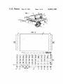
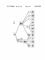
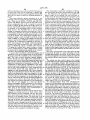
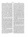
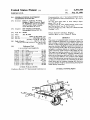
FIG. 1 is a perspective drawing of one embodiment
of a station set utilizing the present invention;
FIG. 2 is a plan layout illustrating a display and vari
ous pushbutton-type keys in an arrangement which is
useful in the invention as shown in FIG. 1;
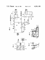
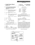
FIG. 3 is a simpli?ed block and line diagram of sta
tion sets of the type in FIG. 1 connected in a telephone
communication system;
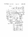
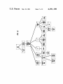
FIG. 4 comprises a simplified diagram of circuits
includes in the station set of FIG. 1;
FIG. 5 is a gate level logic diagram of a coupling
circuit in FIG. 4;
FIG. 6 illustrates electric circuit coil orientations for
65
Calculators with different types of limited telephone
minimizing electromagnetic cross-coupling between
system access are known as represented in the U.S. Pat.
two parts of the station set without necessitating special
No. 4,1 17,542 to Klausner et al. and Macy‘s Superphone
shielding;
3
4,291,198
4
trated. A rectangular display screen permits a larger
text display width and a wider keyboard for facilitating
more rapid touch-typing in the manner previously sug
FIG. 7 illustrates a mechanical interlocking arrange
ment for facilitating the assembling of the station set
elements into a compact integral housing;
gested. Thus, the set depth and width are less than one
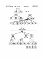
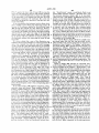
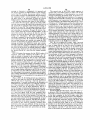
FIG. 8 shows illustrative station set display sequences
in conjunction with screen-line buttons to demonstrate
and one-halftimes the handset length. The height of the
station set 10 is less by about one-quarter than the length
of the handset. In speci?c terms, the overall dimensions
(including rear extension) of one embodiment using the
mentioned K-type handset are about 9 inches wide, 10
inches deep, and 6 inches high.
The result of the described relative proportions in the
use of the station set; and
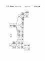
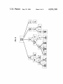
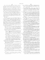
FIGS. 9-15 are process diagrams illustrating opera
tion of the station set in several illustrative processes.
DETAILED DESCRIPTION
In FIG. 1, the illustrated general-purpose electronic
telephone station set 10 comprises a housing including a
station set 10 is that it is convenient to place the set on
a desk or a table without obstructing the view of the rest
of a room where a set is used and without dominating
electric circuit components, to be described, and in
cludes a data processor for coordinating the interactions .. 5 either the room or the table space. Furthermore, the
relatively low pro?le of the station set yields a low
among the other station set elements. The hood 12 is
center of gravity so that the set is not easily tipped over.
attached to the base, as will be subsequently described,
In using the station set in the embodiment of FIG. 1
and encloses display apparatus including a screen 13 of
for plain telephone communication purposes, dialing
a cathode ray tube enclosed within the hood 12. Thus,
base 11 and a hood 12. The base encloses most of the
?exible user-computer interaction. The station set in
signals are entered by utilizing the keyboard 20 after the
handset has been lifted. Upon completion of the calling
cludes several different types of keys collectively desig
information input for each digit, multifrequency dialing
nated as a keypad. One of these types includes a plural
tone signals are automatically transmitted by the station
set 10. Apart from such telephone use, the keyboard 20
25 is useful for inputting information for other purposes.
the display accommodates page-type text displays for
ity of screen-line-associated pushbutton keys, such as
the key 16, arrayed in two columns adjacent to the two
sides of the screen 13. A handset-receiving receptacle is
provided along one side of the station set adjacent to the
hood 12 for receiving a handset 17 which is electrically
connected through an electric circuit cord 18 to other
circuits of the station set. A loudspeaker (not shown) is 30
contained within the base portion 11 and acoustically
coupled through holes 19 in the receptacle beneath the
handset 17. The receptacle also contains an actuating
member (not shown) beneath the handset 17 for operat
ing a telephone system switchhook in a manner well
known in the art.
A keyboard 20 is provided and is advantageously
below and in front of the screen 13. The keyboard in
cludes a plurality of keys for various purposes as will
Furthermore, the station set interacts with a tele
phone switching of?ce either in the telephone mode
already described or by utilizing the switching of?ce
control processor as a host computer-based service.
Likewise, other external host computer-based services
are accessible through the switching facilities of the
telephone switching office or by separate direct connec
tion to the station set 10. Many station set functions
considered herein depend for execution upon a host
computer. However, it will be appreciated by those
skilled in the art that technological advances in minia
turizations will permit a greater proportion of such
functions to be performed by the set without the aid of
a host.
FIG. 2 illustrates in a flat plan type of view a rectan
subsequently be described in connection with FIG. 2, 40
gular display screen 13' and keyboard 20 opened to
and it is advantageously of a width corresponding to the
form a ?at diagram to facilitate illustration. The keys 16
width of the screen 13 and the two columns of keys 16.
in the two columns of keys along the sides of the display
A principal purpose of keyboard 20 is the entry of al
phanumeric text material for display on the screen and
screen 13’ are each associated with a different adjacent
for use otherwise in controlling data processing within 45 horizontal half-line-width region of the screen 13'.
the set and within a host computer. The total width of
the keyboard depends upon the degree of convenience
desired for actuating the keys thereof and ranges from a
relatively narrow keyboard suitable for two-?nger,
full-text typing in one embodiment to a wider keyboard
which is more convenient for tough-typing. A separate
subscriber loop circuit 21 and data signal circuit 22 are
provided for the station set 10 to effect communication
with external systems. It is to be understood, however,
that in an appropriately controlled arrangement both
voice and data can be combined onto a single circuit
pair by either frequency or time multiplexing arrange
ments.
These keys permit a station set user to select a certain
portion of the text in a display on the screen and corre
spondingly signal the selection to a station set proces
sor, and to a host computer to which the station set is
coupled at the time. Thus, actuation of the respective
keys 16 do not represent ?xed functions or cause corre
sponding characters to be displayed on the screen. Co
operative use of those keys 16 and screen 13' give the
telephone set user convenient access to computer ser
vices as will be described.
A row of keys, such as the key 23, is arrayed along
the bottom edge of the screen 13', and these are further
designated as screen steady function keys. The result of
actuation of a key 23 also does not appear as a particular
Handset 17 provides a convenient measure of the
station set size. In one embodiment using a Western 60 displayed text character. These keys permit user selec
Electric Company K-type handset, the length of the
handset 17 is slightly less than the front-to-back depth of
tion of predetermined program control options which
frequently recur in different steps of various station set
processes. Some examples include display paging ac
the station set 10 (not including any rearward extension
tions such as restart the program, explain the choices
to accommodate a portion of the neck of the cathode
ray tube providing the display screen 13). In a similar 65 offered by the current display, back up to a prior pro
cess step, or display more information of the type al
context, the set depth is slightly less than the width
ready displayed. Thus, keys 23 are display-action
thereof assuming a cathode ray tube arrangement pro
associated keys whereas keys 16 are display-line
viding a substantially square display screen 13 as illus
5
4,291,198
6
associated keys. Accordingly, it has been found to be
It is to be understood, however, that different propor
advantageous in one embodiment to dedicate a key to
tions of the operational processing can be accomplished
each such action option type and leave the screen-line
associated keys 16 for other line-associated selections
that are unique to a particular display. The keys 16 and
23 are sometimes called “soft keys" because they permit
time permits within the limit of having a small, conve
niently usuable set. Although the host 40 is shown at a
separate location from the of?ce 39 for convenience of
within the set and remotely as the state of the art at any
the telephone station set user to exercise speci?c control
over the direction of execution of a computer-based
process in which the set is engaged.
illustration, it can also be located within the of?ce or on
the subscriber's premises where the of?ce is a private
branch exchange (PBX) in such premises. In the latter
The keyboard 20 advantageously includes more than
enough keys to produce a full set of character codes
according to the recommended USA Standard Code for
case the host functions and the PBX control functions
Information Interchange (ASCII), e.g., the 128 different
codes representing numerals, letters, and various func
remote from the of?ce 39 and coupled thereto by ordi
nary voice grade circuits, standard practice utilizes data
modems (not separately shown) at the set and the of?ce
are advantageously all performed by a single processor.
In some applications where the sets 36-38 are relatively
tions which can be signaled from the keyboard to the
station set processor using upper and lower case key
for digital signals.
functions and certain predetermined combinations of
FIG. 4 comprises a simpli?ed diagram, partially in
key actuations as is well known in the art for ASCII
schematic form and partially in block and line form, of
keyboards. Textual characters corresponding to actua
electric circuits of the station set of FIG. 1. The illus
tions of these keys are displayed on the screen, and 20 trated circuit elements are primarily commercially
control functions corresponding to actuations of the
available elements, and where this is not the case addi
keys usually appear as actions in formation of the dis
tional schematic information is shown in this ?gure or in
play, e.g. space, new line, or carriage return.
FIG. 5. In order to facilitate and understanding of the
Included in the bottom row of the keyboard are some
examples, such as the ASCII keys for “carriage return”
25
operation of the invention, the diagram of FIG. 4 shows
primarily only data ?ow paths as realized in separate
27, “new line" 34, and “interrupt" 28, as well as some
additional ?xed key functions such as a space key 26,
space divided or time divided channels between equip
36-38 are designed to be used with a host in the present
state of the art and stand-alone use is usually employed
operation security and central of?ce billing information.
ments. The provision of timing and control arrange
shift key 29, a CTL control key 25, and break key 35.
ments to implement such separate channels for opera
That same bottom row of keys also includes three
tion of the illustrated equipment elements in accordance
additional (non-ASCII) keys 30 through 32. These keys 30 with an illustrative process diagram, to be described, is
represent certain additional ?xed functions often found
obvious to those skilled in the art.
in computer-based services but which use different
The handset 17, the various types of keys of the key
character combinations in the different services. These
pad 15, the display 13, and a loudspeaker 42, all previ
keys 30 through 32 in the illustrative embodiment are
ously mentioned, are cooperatively coupled together by
sometimes called “hard" keys, to distinguish them from 35 a data processing facility including a processor 43. That
the aforementioned soft keys l6 and 23, and because
processor can be implemented in various ways depend
their respective functions relate more to control of
ing upon how much processing is to be done in the set
hardware than software. Typical functions of the type
and how much in the host computer. In the illustrative
mentioned which are common to various computer
embodiment processor 43 controls basic telephone
based services include delete last character CH, delete 40 functions (using the ASCII keyboard 20 for dialing).
line LN, and stop terminal output FRZ. The keys 30
For screen display of text information and for other
through 32 provide, when actuated, function call char
more elaborate functions, processor 43 cooperates with
acters for those three functions, respectively; and the
a host computer such as a Digital Equipment Corpora
processor in station set It] automatically translates the
tion PDP 11/45 computer. In this environment proces
function call characters to the corresponding call code 45 sor 43 advantageously includes a microprocessor such
used for the particular computer-based service then
as the INTEL Corporation 8748 microprocessor coop
interacting with the station set. The necessary data for
eratively coupled with a program memory, such as the
this translation is obtained by the processor during ini
INTEL 8755A programmable read only memory and
tial handshake, i.e., set up operations, with the service
the Intel RAM and I/O Expander 8155 which also
when it is ?rst connected.
50 provide supplemental input/output port facilities and
FIG. 3 illustrates several general-purpose electronic
supplemental buffer memory for the microprocessor in
telephone station sets 36, 37, and 38 of the type herein
a manner now well known in the art. Such cooperative
before described in connection with FIGS. 1 and 2. All
arrangements are taught, for example in the INTEL
three of the station sets have two-wire voice lines 21
“MCS-48 TM Microcomputer User‘s Manual,“ 1978,
(subscriber loops) and data circuits 22 coupled to a
pages 3-9, 5-7 to 5-9, and 6-33 to 6-49. This arrange
telephone switching of?ce 39 such as a class 5 telephone
ment provides suf?cient buffer storage for approxi
of?ce switch or a private branch exchange switch. A
mately one-half of a fully written screen, which has
digital switching of?ce such as that described in the
been found to be adequate for the general purpose sta
aforementioned Alles or McDonald patent is one exam
tion set application illustrated herein.
ple of such an of?ce, and the disclosures of both such 60
A data input port on processor 43 receives multibit
patents are hereby incorporated herein by reference in
station set identi?cation number signals from ID
their entirety.
switches 56 included in the station set and settable by
Within the of?ce 39, the data circuits are advanta
the owner of the set to a predetermined number repre
geously switched into communication with a host, such
sentation which is included in return status data mes
as the host 40, as a peripheral unit. Sets such as the sets 65 sages, to be described, for providing data processing
only for testing, demonstrations, or emerging situations.
One output from processor 43 is a CLKR signal sup
plied to a clicker 74. That clicker is, for example, a relay
7
4,291,198
arranged so that when actuated its armature strikes a
solid member, e.g., the station set chassis, to provide an
appropriate clicking sound audible to the station set user
upon actuation of any key on the keyboard 20, or associ
ated with display 13, for informing the user that the
processor has responded to the key actuation. Clicker
74 is selectively disabled by software instruction from a
8
processor 43 signals defining the nature of a particular
character to be displayed and the position on the display
for that character, and it converts that information into
the necessary de?ection and beam control signals to
write that particular information in the particulr region
indicated on the screen 13.
During the course of a communication with the sta
tion set circuits as illustrated in FIG. 4, incoming ring
ing signals are received by way of the circuit 21 to alert
cussed.
Keyboard 15 includes the various types of set 10 keys 0 the subscriber. The ringing signals are coupled from the
user or a host computer as will subsequently be dis
as hereinbefore outlined. Actuations of these keys are
communicated to processor 43 in two different ways.
circuit 21 through a limiting resistor 63 and a direct
current blocking capacitor 66 to be full wave recti?ed
The soft keys 16 and 23 and the hard keys 30—32 are
in a bridge rectifier 67. Some of the high frequency
connected to processor 43 by respective logic level
ripple is bypassed by a shunt connected capacitor 68,
signal leads in a twenty-two lead bus 54. Processor 43 5 and the remaining signal energy is limited in amplitude
by a breakdown diode 69 prior to coupling to a tone
recurrently samples the signal states ofthe leads in parts
ringing circuit 70 such as one using the S2561 ringer
of the process utilizing the hard and soft keys. The
chip of American Microsystems, Inc. That chip, and
sampling rate is sufl'icently high to assure detection of
associated resistors and capacitors connected to the
any changes. States of the keys of keyboard 20 are re
chip in a manner well known in the art, accomplish the
currently scanned at all times by a scanner encoder 48,
conversion of the ringing signals into the desired ring
such as the KR 2376 keyboard encoder chip of the
ing tone, the latter tone is then utilized to actuate the
Standard Microsystems Corp. That circuit provides
to the scanner encoder where an actuated-key sample 25
causes a 7-bit snapshot of a clock pulse counter to be
applied to a latch 24 to identify the actuated key. The
loudspeaker 42 for alerting the subscriber.
Assuming an incoming voice signal call, the sub
scriber answers by lifting the handset 17 and thereby
releasing a switchhook actuator (not shown) for allow
ing the various pairs of swtichhook contacts to close.
snapshot is accompanied by an eighth but which gates
all eight bits into the latch. Output of latch 24 is coupled
Two sets of these contacts HS] and H82 close the line
circuit 21 for direct current through to a hybrid net
to processor 43 by way of an eight-bit bus 49. The
eighth bit is used as a flag in latch 24 to signal, when
work 71 which is, in turn, coupled to the handset 17.
The hybrid network 71 is of a type currently in use in
interrogated by processor 43, that there is information
commercial telephone service for coupling the separate
to be processed. A lead 51 from processor 43 carries
signals which reset latch 24 after its contents have been
read so that a new snapshot can be received. The total
circuits of a receiver 72 and a transmitter 73 to the
clock signals to the keyboard for sequentially sampling
the respective key states, and the samples are returned
two-wire line circuit 21. The hybrid network includes a
hybrid transformer 76 as well as varistor limiting de
sequence of sampling, snapshotting, reading, and reset
vices 77 and 78 and a hybrid balancing impedance 79 in
ting occurs more than 50 times per second to be sure
a common branch of the otherwise separate receiver
and transmitter circuits.
In order to initiate an outgoing call, the station set
Another input to processor 43 provides an FD/HD 40 user enters calling information using the keyboard 20 as
that no keyboard key actuations by even a fast human
user are missed.
(full duplex, half duplex) option signal from a set of
previously noted. Processor 43 collects the sampled key
option switches 57 also included in the station set and
available to the station set user for selection during any
information by way of the bus 49 and supplies that
signal OFFHK as provided via contacts H55 in FIG. 4
and which are part of the aforementioned switchhood
associated with the handset 17.
A random access memory display controller VRAM
59, such as the Matrox Electronic Systems Limited of
Canada video random access memory MTX1632A, is
Thereafter the sample and position information are
supplied to the VRAM 59 which develops the neces
sary outputs to control the cathode ray tube for writing
information to the host computer, in a manner to be
described, to be associated with display-position-con
particular call connection or other station set use. Still
another lead to processor 43 is a handset hood status 45 trol address information and returned to processor 43.
utilized with the microprocessor for exercising control
corresponding characters in appropriate parts of the
screen 13.
In addition, when the dialing information has been
collected, and if the calling station set subscriber is
off-hook as indicated to processor 43 by closure of
of the driver circuits for the display screen 13 on cath
contacts HSS, processor 43 supplies the dialing informa
ode ray tube 14, FIG. 6. Such driver circuits are not
separately shown but are advantageously those manu 55 tion to a tone generator 47 by way of a circuit 50. That
factured by the Electronic Display Division of Ball,
Incorporated. Nine-bit addresses are provided to
VRAM 59 from a data input/output port of processor
43 on a multibit bus 60. Data is provided to the VRAM
59 by way of a multibit data bus 61 extending from a
processor input/output port. Read-out signals are also
provided from VRAM 59 to the processor by way of
generator is advantageously a Motorola MC14410 2
out-of-8 tone encoder. Generator 47 produces charac
ter-distinctive multifrequency tones corresponding to
the respective dialing characters. Each tone is produced
during a ?xed interval and coupled through a trans
former 80 and the switchhook contacts H81 and HS2 to
the line circuit 21.
the same bus 61 as needed, for example, in a display
When this dialing signal outputting function begins,
scrolling operation. An analog signal output port from
the processor 43 also provides a DRELY signal which
VRAM 59 provides signals on a three-circuit bus 62 for
coupling to the cathode ray tube separate signals for
actuates a dial relay 81 to close contacts DR1 in series
controlling horizontal de?ection, vertical de?ection,
conductor end ofthe secondary winding oftransformer
and beam intensity. The VRAM 59 thus receives from
80 to complete the tone output circuit. Additional dial
with a direct current blocking capacitor 82 at the tip
9
4,291,198
relay contacts DR3 in the handset are opened in the
circuit of the transmitter 73 for disabling that circuit
during the transmission of dialing signals from genera
tor 47. Also, contacts DR2 are opened to remove a
short circuit from a resistor 83 in the circuit of the re
ceiver 72 so that the dialing tone energy portion cou
pled back through hybrid network 71 is at an appropri
ately low level so that it does not disturb the user.
10
Assuming ?rst that the RS serial data coupling mode,
e.g., to a modem, is selected by the RS/CL option sig
nal, the lead 91 signals are applied to one input of a
NAND gate 93 which also converts the signal from the
TTL levels to the RS standard levels. A low BRK
signal pulse from the keyboard, by way of processor 4&3
and a monostable trigger circuit 95, corresponds to
actuation ofa BREAK key 35. Otherwise when BRK is
high, gate 93 inverts data signals from lead 91 to serial
After each dialing tone has been transmitted for the
necessary called party number, processor 43 disables 0 data output circuit 22’. The serial data input signal in
circuit 22’ is inverted by a single-input NAND gate 96,
dial relay 81 and thereby restores its associated contacts
which also converts the RS standard signals to the TTL
to their normal condition. After all dialing tones have
levels, before coupling to one input of NOR gate 97.
been transmitted, the subscriber follows usual call
That gate has the RS/CL option signal applied to its
progress tones until the completion, or other dispo
sition, of his desired connection by the switch office. h. 5 other input. Output of the gate 97 is coupled through a
further NOR gate 98 to the return lead 92 to the UART
After completion of voice signal exchange with the
89.
called party, the subscriber hangs up by restoring hand
set 17 to its receptacle in the station set 10, the switch
hook switch opens its contacts H55 and thereby corre
spondingly signals processor 43 so that the processor
program can respond accordingly. The called number
display remains on the screen 13 until new data is sup
For current loop coupling to a host computer-based
service, the output of NAND gate 93 is inverted and
restored to the TTL levels in a single-input NAND gate
99. The output of that gate is coupled through an in
verter 100 to a signal limiting coupling element 101
including a current limiting resistor 102 and a shunt
plied for the display area occupied by that number or
limiting diode 103 connected to the positive supply.
the display is otherwise cleared by user command. For
25 Output from the element 101 is coupled through an
example, actuation of a RESET switch 45 in FIG. 4 by
the user clears screen 13 and reinitiates the program of
microprocessor 43.
For the purpose of data communication, processor 43
has a data input/output port coupled by way of a fur
ther multiconductor bidirectional bus 86 to the bit-par
allel transmit and receive ports of a universal asynchro
nous receive transmit (UART) circuit 89 such as the
optical coupling element 104 including a light-emitting
diode 106 which cooperates with a photo transistor 107
to supply corresponding current loop signals to the
transmit loop of circuit 22". Similarly, the receive loop
of circuit 22" is applied in parallel across the light-emit
ting diode of receiving optical coupling element 109 and
the limiting diode of a signal limiting element 108. Ele
ments 108 and 109 have their respective resistor and
Harris Corporation UART chip 6402-9. UART 89 also
transistor connected in series between a positive supply
has bit-series input/output connections to the outside 35 and ground. The midpoint between the resistor and
world by way of coupling logic 90 which is shown in
transistor of those two elements is coupled through
greater detail in FIG. 5. That logic further couples
NAND gates 110, 111, and 112, and an inverter 113, to
UART signals by way of the circuit 22 to a host com
a second input of the NOR gate 98.
puter, either directly or via a data modem (not shown),
NAND gate 112 has applied to another input thereof
as will be further described in regard to FIG. 5. An 40 the RS/CL option signal. When that option signal is
oscillator 87 has its output coupled to an input of a rate
low, NAND gate 112 is blocked; and its corresponding
selection circuit 88 which is controlled by a four-bit
high output is coupled through inverter 113 as a low
output signal Sqb-3 from the option switches 57. The
signal from circuit 88 is sixteen times the bit rate and is
converted by logic in UART 89 to the required bit
series and bit-parallel clock signals for use in the
UART. Coupling logic 90 also receives from the
switches 57 an RS/CL signal indicating which of two
input to enable the gate 98. Thus, the series input data is
inverted once in each of the gates 96 and the enabled 97
and 98 before reaching the lead 92. On the other hand,
when the RS/CL signal is high, gate 97 is blocked; and
gate 112 is enabled to couple data from NAND gate 111
through to the NOR gate 98.
circuit interface standard signals is to be used and an
The RM/LOC option signal is applied directly to one
RM/LOC signal indicating whether remote or local 50 input of NAND gate 110 and coupled through an in
signals should control the screen 13 display. An addi
verter 116 to a ?rst input of NAND gate 117. The same
tional FD/HD signal from switches 57 informs proces
input to gate 117 is also used as a LOCAL signal which
sor 43 whether the user has selected full duplex or half
is applied to the processor 43 to keep it informed of the
duplex operation.
circuit option selected by the user. Thus, one of gates
FIG. 5 is a gate level schematic diagram of the con 55 110 or 117 is always enabled and the other disabled.
necting logic 90 in FIG. 4. Bit-series signals are coupled
When it is desired to receive input from a remote
from the UART 89 on an input circuit 91 and to the
source, the high RM/LOC signal enables gate 110 and
UART on an output circuit 92. The output of coupling
forces gate 117 to be disabled thereby enabling NAND
logic 90 corresponding to the circuit 22 is one or the
gate 111. The RS/CL signal must be high at this time
other of the known RS232 (here RS) or current loop 60 also so gate 112 is enabled to couple received data sig
(here CL) interface standards for signal source impe
nals from gate 111 on through NOR gate 98 toward the
dance, voltage and current levels. Separate circuits 22'
UART 89. A low RM/LOC signal is inverted to enable
and 22" provide the selected standard coupling. Which
gate 117, and it blocks gate 110 thereby enabling gate
of the two output circuits 22' or 22" will be used at any
111. Input from the coupling element 109 is blocked, but
given time depends upon user selection of an RS/CL 65 local output signal from the output of NAND gate 99 is
option signal from the option switches 57 and comple
now coupled through an inverter 118 and the gates 117,
tion of a corresponding transmission circuit connection
111, and 112 toward the UART. Thus, the user controls
the times either when the data output of the station set
to 22' or 22" at the back of the station set.
11
4,291,198
will be recirculated, e.g., to the screen 13 of the same set
or when that screen will be employed to display data
received from a remote source through the element 109.
The LOCAL option is useful for checking operation of
the set.
Three user-selectable options described up to this
point may seem to overlap, but they serve discrete func
tions. These are the RS/CL, FD/HD, and RM/LOC
options. The RS/CL option is used to select the correct
circuit con?guration 22' or 22" to match the external
facility to which the data portion of set 10 is to be con
nected. The FD/HD option is used to conform proces~
sor program to the operating mode of a host computer
based service. The FD/HD state is set by switch
change or command whichever occurred last. That is, 5
12
FIG. 6 illustrates a particular orientation of the hy
brid transformer 76 and the vertical deflection coils 118,
i.e., the de?ection coils operating in the audible fre
quency range, of the cathode ray tube 14 which in
cludes screen 13. Circuit elements are necessarily close
to one another in the illustrated station set. It was found
that the cathode ray tube vertical oscillator coil and
deflection yoke produced strong magnetic ?elds which
injected noise into the circuits in which the hybrid coil
76 was connected. Rather than shield either of those
coils, it was found that the hybrid coil 76 could be posi
tioned to pick up a relatively low level of interference
audible in receiver 72. This is achieved when the hybrid
coil is located so that its mutual inductance with the
combination of the vertical de?ection yoke coil and the
in full duplex operation the station set keyboard output
vertical oscillator coil is at or near zero. The most ad
is transmitted to the host which echoes it back to con
vantageous position was found in the illustrated em
bodiment to be an orientation in which the longitudinal
axis of the straight core on which the coil 76 is wound,
when the core is in a plane parallel to the bottom of the
set, was at approximately a 30-degree angle to the pro
trol the set display, but in half duplex operation the set
keyboard output is used (through the LOCAL mode)
when available to control the set display and the host
output is used (in the REMOTE mode) to control the
set display as to information originated by the host. [11
jection of the neck of the cathode ray tube in the plane
either case of course, the display control is exercised
of the core. The longitudinal axis of the tube was at an
angle of about 30 degrees to the plane of the bottom of
through UART 89, processor 43, and VRAM 59. Fi
nally, the RM/LOC option is available only when the 25 the set. In that embodiment, the vertical oscillator 115 is
CL option is in effect and is used to select a correct
circuit con?guration for either independently testing
the station set or implementing display of set transmit
ted data in the half duplex mode of operation.
It can be seen from FIGS. 4-5 that the handset and
associated voice circuits depend upon use of the keypad
15 and processor 43 to establish a voice communication
path. The voice circuits thereafter operate indepen
dently through the voice signal port represented by
located on the opposite side of tube 14 from coil 76 and
with its coil in approximately the same plane as the neck
of tube 14.
FIG. 7 is a cross-sectional view of the station set base
11 and hood 12 taken on a plane extending vertically
through approximately the center of the display screen
13. All circuit elements except the cathode ray tube and
the keyboard 20 have been omitted to facilitate illustra
tion.
connection to circuit 21; and the keypad and associated 35 The cathode ray tube is held in place in the housing
by a semirigid rod type support frame 119. Keyboard 20
data circuits operate independently through the data
rests on a rectangular shoulder 120 extending around
signal port represented by connection to circuit 22. The
the front wall of the base portion 11 and along a part of
combination of these discrete capabilities in the single
the two sidewalls thereof (only the front wall portion of
station set gives new freedom to the set user. For exam
ple, the user while engaged in a voice communication 40 the shoulder 12!) is shown in FIG. 5). The keyboard 20
is made large enough to press against the screen 13 of
with another person and using handset 17, can also
the cathode ray tube for slightly de?ecting the frame
119 rearward (to the left as illustrated) when the key
board is in place in the illustrated rest position. This
must be one sharing the same host computer, or their
respective hosts must have data communication capabil 45 wedges the keyboard 20 into position between the front
wall of base portion 11 and the lower edge portion of
ity. Thus, the host computer, or an aide using the sec
the screen 13, which portion is also simultaneously
ond set, can keep the ?rst set user informed of additional
masked in a partial bezel fashion by the left-hand edge
incoming voice calls on other lines, and that first user
(upper edge in FIG. 1) of the keyboard.
can respond with desired disposition of such additional
engage in a data communication with a host computer
using the keypad 15 and screen 13. The other station set
calls. The set user engaged in a voice call simulta 50
An inverted-u-shaped bezel 115, advantageously
stored information and update the data. In any case, the
formed of a flexible plastic such as polyvinylchloride, is
further shaped to give the sides and bottom of the U an
interior bevel effect so that the bezel cooperates with
other party in the ongoing voice communication is
the sloping keyboard 20 to complete an inwardly slop
neously interrogates his host computer for such data as
telephone numbers, appointments, or other previously
55 ing frame masking the edges of screen 13. The ends of
unaware of the data communication.
the inverted-u bezel 115 rest on the top face of keyboard
Similarly, if handset 17 is not in use but the set user is
20 while the interior edges of the bezel bear against
engaged in a meeting with one or more visitors, silent
screen 13. The hood 12 is assembled after the tube and
data messages can be exchanged with the host com
bezel are in place by pressing opposite sides of the hood
puter; and a visitor that cannot view screen 13 will be
unaware of the message content. The small size of the 60 toward each other and lowering the hood over the
bezel and the tube until a downwardly extending index
set and the recessed screen (as will be discussed) make
finger 121 engages an aperture in a lip 122 at the back of
this type of private video message operation possible.
Likewise, if the set 10 is powered up while the user is
the base portion 11. A lip 124 around the front opening
out of the room, a message can be left on the screen by
a remote caller if the host security arrangements permit.
of the hood holds bezel 115 against screen 13. Then the
sides of the hood are relaxed to allow latching ?ngers,
The host must however keep track of the state of the
such as the ?nger 123, to engage a cooperating recess
screen and store any surplus messages to prevent over
126 in the sidewall of the base portion 11. The keyboard
is then inserted by pressing the left edge, as shown in
writing of a first message by subsequent messages.
13
4,291,198
FIG. 7 against the lower tips of bezel 115 to press the
bezel and tube 14 toward the left and thereby similarly
14
last. “Switch-hook" causes a switchhook ?ash to get
de?ect the frame 119 sufficiently to allow the right edge
central office operator attention. “Personal Asst“ calls
the personal assistance display 143, to be described.
of the keyboard to be snapped into the base 11. This
arrangement interlocks the keyboard 20, screen 13,
bezel 115, and hood 12 in position so that they are rela
“New services" calls display of additional services not
already on the initial display 140; and in particular, it
tively immovable.
to which the user may have access by connection
makes available a list of other computer-based services
In its rest position, the keyboard with its finite thick
through the central offices 39 and interaction using the
ness is unable to pivot freely out of the base portion 11
various keys of the set 10. "Call Host" enables the user
because of the pressure applied by the de?ected frame 0 to interact with the particular host computer-based
119 through the cathode ray tube. However, the key
service, e.g. 41, of the set 10 as users of conventional
board is advantageously separately removable by insert
character display terminals do in the present state of the
ing a blade type member (not shown) through a housing
art. “Lock” disables the entire station set 10 for further
aperture 127 to force the front edge of the keyboard
operation by way of transmission or access to processor
upward and thereby additionally de?ect the frame 119
43 memories until the user types in his or her personal
by an amount which is sufficient to permit removal of
identi?cation number (different from the set identi?ca
the keyboard without first removing the hood 12 and
tion number in the switches 56).
bezel 115.
The “Call by Menu“ display 141 shows callable num
It is now evident that a user of the illustrative em
ber group types that the user has previously stored.
bodiment herein types messages to control processor 43 20 These include some typical categories for purposes of
and a host computer but does not send such messages
illustration. One of these is "Co. Admin." and its selec
via the circuit 21 to the office 39 so there is no switched
tion causes display 142 to appear showing company top
data path directly between a pair of sets. The only data
management of?cials (illustrated by organizational
path 22 interaction between sets is as different periph
functions but actual names can, of course, be used), and
eral units sharing a common host computer that can act
selection of any of these items of display 142 causes the
as a message relayer, with or without extra processing.
set 10 to call that person’s number directly. Alterna
Any utilization of the illustrated general-purpose
tively, activation of a predetermined one of keys 23 for
telephone set is initiated by turning on a local power
“traverse” followed by actuation of a key with display
supply (not shown), operating the reset switch 45 in
142 causes a new display of names of the next lower
FIG. 4. and typing in a personal identi?cation number
level of administration in the selected organization. The
to unlock set operation. This causes an initializing dis
play, sometimes called a “menu,” to be presented on the
screen 13 for providing the user with an indication of
“Restart" item allows the user to return the process to
display 140.
Again in display 140, selection of “Personal Asst”
the initial options that are available in that phase of
causes display 143 to appear showing various types of
operation. FIG. 8 illustrates in the upper left corner 35 services available in this category. “Set Reminder“ calls
thereof one form of that initial display. Actuation of the
a further display (not shown) to enable the user to pro
key 16 adjacent to a label causes the host computer to
have the screen erased and display a new menu, or set of
selectable options, corresponding to the actuated key
gram the set 10 to ring at a preselected time and display
then the reason for the reminder. “Read Appt” calls a
display of the next twelve appointments the user had
16. Three of the additional displays that can be called, 40 previously stored in accordance with instructions dis
by actuating the one of the screen line keys 16 adjacent
played by selection of “Make Appt”. The “Time &
to an item displayed, are also shown for purposes of
Date” and “Z-Month Calendar" items display current
illustration. The keys to be activated are indicated by
time and date or the calendars for the current month
the keys marked with an “X” in the drawing and associ
and the next month. “Read Mail” displays messages that
ated in the drawing by a line to the corresponding addi 45 may have been recorded in the host computer memory
tional display.
In the initial display 140, different telephone calling
operation types are shown. These include calling by
number (enables dialing by typing a number on key
board 20), by menu (calls a repertory-type function and
name list used to cause the set to dial automatically a
previously stored number for a selected name or func
by callers while the user was away from the set 10.
"Send Mail" calls a process to enable the user to enter
one or more addresses and a message to be sent out by
the set 10 when it can gain acces to each addressee. The
"Pink Slip" option calls a subroutine and appropriate
corresponding displays to enable either the display of
calling data for previously received calls that should be
tion), or by typing (allows a user who already knows
returned or the leaving of a call-back message for an
the key label for a desired function or name in a later
other subscriber having similar equipment. “Back up“
display ofa type-by-menu sequence to type in that label
causes the program to retrace the menu display se
and cause the set to transmit the corresponding number
quence one display at a time. “Restaurant'” displays a
predetermined list of restaurants so the user can select
one to be called by the set 10 without the user being
or put up the corresponding display as may be appropri
ate). The user‘s secretary can also be called directly by
selecting the corresponding one of keys 16, and simi
required either to recall or to input the specific number
larly selection of "Top 10" results in display of the 60 each time that it is to be called.
names of the user’s top 10 aides. The "Explain” key
Instructions to processor 43 will now be considered
causes a text display to be presented explaining how to
deal with the options of the display that included “Ex
plain". This display option and others such as “back
for carrying out elementary operations which are neces- ,
sary for putting displays on the screen 13, user interac
tion with a host computer using the station set keypad,
up" or "restart" in FIG. 8 are, of course, not necessary 65 processing call connections for voice communication in
for station set embodiments having the keys 23 previ
calls initiated by user dialing a called party or by an
ously described. “Answer/Hand-up” causes the set to
other party calling the set user, and set data interaction
perform whichever of the two functions it had not done
with the host. Basic commands to the microprocessor
4,291,198
15
16
43 are listed and described in Tables I and II which
TABLE I-continued
follow Interactions produced by different combina~
()p-Code
tions of these commands make it possible to perform
higher order functions, such as those to be described in
connection with FIGS. 9-15. Various combinations of 5
the latter functions directed by the station set user or by
Parameters
Comments
options, to host‘
It is observed in regard to Table I map the character
the host computer service produce the externally evi-
"t" has mutiple uses. When generated alone it has its
dent set functions such as those previously herein outusual text significance. When in a number string of
lined‘ Process implementation for other tasks which a
op-code “u“ it causes an outgoing call to be timed.
user may want to perform will be apparent to those 10 When pre?xed by the ESC character, ‘*t“ is itself an
skilled in the art from the illustrations given‘
opcocle.
Table I is a summary of illustrative command codes
Table II explains the use of the parameters “B” and
for the set 10‘ Currently these are prepended with an
“C" for the command “s" of Table I. A particular pa
ASCII ESC (0333) code, i.e., a prefix indicating that the
rameter “8" is specified by the host or by a set user by
code which follows has a meaning other than that in the 15 actuation of the indicated keyboard numerical key in a
usual ASCII seL An * by a comment in Tables I and II
indicates an automatic return to scroll mode upon com-
Table I “5“ command. For that parameter the function
named "1 lh? Column "Meaning" ‘5 translat?d t0 the
pletion of the indicated operation. All operations except
chafaqel' Indicated by parameter “C‘ . “B’ and “C” are
“>i“ restore the screen cursor to its initial position i.e., its 20 both Smgle ASCII characlfim Deffllllt Valu?s "1 Column
position just prior to execution of an instruction presC 3T? lh? Ones autPmatlcany ullllzed by the Set PTO
ently being executed. As known in the art, the cursor
has a visible part and a memory part. The latter part is
Cessor "'1 one embodlment after RESET key acluallon
and befofe any _5 cod?s are recclved- For example,
an address stored in memory of processor 43 indicating
fmy P0§_5lble llosl 1} programmed 80 ‘that, upon ‘recogniz
where mg next Character will be Written in the display
irig the identification code for a station set 10, it uses the
_
__
‘,
__
V
‘25",,
“H
.
The visible part is advantageously the blinking of either
I 5 Code to Supply a Few lame 9f vallles for “C wind?
:1 character that may already be in the selected location
or of an underline segment placed in that location if
there is no other character already there. The blinking
‘t uses for the functlon? ldeml?ed m‘the Meanmg
bolumn‘ In subscqugf“ ‘meracnons with th? host the
P'QCeSSOY 43 automaucany P?forms ‘he req‘med trans‘
character function is further utilized herein in connec- 30 lanons (See FIG‘ 15) to accommc'date ‘he host‘
tion with the screen line keys 16 as will be subsequently
TABLE II
discussed.
C
(default
value
TABLE I
Op-Code
Parameters
a»f
[string]
Comments
B
shown)
35
string is label for one
DC3
of the (1 buttons on the
left side of screen 13
l
@
Set the character associated with
2
#
Set
the Delete
the character
Characler
associated
key to C -
the second‘ and so on).
[string]
the Delete Lme key ‘0 “C ‘~
string
Labets labels
are [6ftthejum?e¢
buttons
40
on the right side of the
Scmen pig“ for [he mp‘
\
3
The STET character is prepended
S“ on] Lab?ls are ‘light
(by translation in processor 43)
to keyboard characters also used
Enter 8cm“ mode.
‘Used c y
45
by the host for a hard key
for
function, eg. so those
dig la'irfmordinary
characters can be freely used for
ru'nlz?sg ‘gem )
q
[B] [C]
'
ASCII purposes without the hard
,The parameter Speci?ed
key functions. The host operating
b
system deletes the STET
._B.. is wt to the
vilue
(Sea
50
character and the host uses the
TABLE 1'1)
H
t
H
i
__
H
_,
T g
,
,
remaining character in its usual
'.
_
‘
non-delete fashion,
s?lli‘tibs 6“ “legals b
Z3215 232:: ‘e “um er
4
NAK
.
u
[number string]
55
'
.
0 : half duplex (overrides FD/HD
’
option switch);
Bit 1, 1 : raw mode 0 = normal mode;
mm“ mm"
Bit 2‘ i : clicker active, 0 : clicker
characters‘ such ‘as NL
off, The values for default
(Ohm ‘to “use “an” or
[he Swmhhlmk m be u H
returned to host‘ and
character NAK (0053) are: clicker
60
l
“643) F“ can”: the “an
u’ be “mm
f
Column "1 C
active, normal mode‘ full duplex.)
5
DEL
The pad is Set to “Cu,
6
DEL
The character emitted when the INT
(The "INT " character causes the
y‘Posilmn cursor lor ‘4 RAM
1“ row ": r " 40* and
Y
'
key is pressed is set to “C‘\
Emc‘f ‘My m‘ld? .
[r] [c]
tlb'ti
ig?glrznsiicoliolrgun ldiglxy
‘may’ by useiopuon’
it
The 3 least signi?cant binary
bits of “C" are specified by user
'iidw
string |s)number
g‘glgafginfjm?e string
W
De?ne a STET character as "C".
“hut rm, ‘hc Semnd and
ju'sti?eid‘
ESC
.
recognizes as the start/stop
output character is given by “C“.
(“a" for top one‘ “b“ for
gel
Meaning
Th8 Character Whlch hDSt
40*
*Rclml“ 5mm)" Sc‘
status. such as serial
number and user-selected
host npera'ing “5mm ‘0 Xermina‘e
65
output to the station setv A
value of NULL (0) causes a BREAK
signal to be sent to the host.)
17
4,291,198
At line 8:0 in Table II, a value of NULL (0), e.g.,
in a table provided by a new host, indicates that the host
does not support this feature, and the set processor will
then suppress transmission of the key activation to the
host if the user calls for it.
The “pad character” mentioned in Table II at the line
B=5 is a nondisplay ?ller sent by host when it needs a
18
return) is a status message and indicates that the process
must collect certain information, determined by the
location in the process at which the message is used, and
transmit it in the character string to the host computer.
SCROLL moves all lines of text on the screen 13 up one
line and clears the bottom line. SCROLL can occur
delay without disturbing its peripheral units. The sta
tion set learns during initializing handshake with host
only when in the SCROLL mode and with the cursor
on the last line of the display. Figure references con
tained within a block indicate the ?gure where process
what the character is. When the pad character is re
details are shown. The term RESET indicates an opera
ceived by the set processor, it is ignored. This allows
the host to implement timing delays by emitting a num
ber of pad characters.
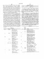
FIGS. 9 through 15 represent the operation of pro
tion which clears the text displayed on screen 13 and
causes the process to go to the SCROLL mode.
Processor 43 recurrently operates in accordance with
the chart of FIG. 9. Thus, in PROCESS CONTROL
cessor 43 depicted in the form of program structure if) MESSAGE (PCM) the processor obtains a control
message from its internal data buffer (not separately
charts. These charts show what the processor does in
shown) and executes one of the seven selection type
recurrent cycles of operation, and they are readily un
functions illustrated in the second level from the top in
derstandable to programmers skilled in the art. Such
FIG. 9. These selection functions correspond to the
charts are prepared in accordance with a technique
called "hierarchical structure." This technique is ex 20 Table I processes. The process then returns to the data
plained in detail, for example, in Chapter 2 of Principles
of Program Design by M. A. Jackson, Academic Press,
buffer to obtain a new control message. Each of the
New York, 1975. Each process charted ?ows from top
cated in more detail either in FIG. 9 or in one of the
selection processes in the second level of FIG. 9 is indi
FIGS. 10 through 13. In the latter ?gures, the same
to bottom as illustrated in the sense that for a block at
any given level in a chart, the details of the operation 25 selection block of FIG. 9 is repeated at the top of the
chart in the further ?gure to provide convenient cross
performed by that block are depicted in one or more
reference.
blocks in one or more lower levels of the chart con
FIG. 9 and each of the charts in the FIGS. 10 through
nected thereto by lines in the chart.
12 include an iteration block PROCESS EXTERNAL
Components of a chart include elementary compo
nent blocks which have no parts; and, after each execu 30 INPUTS (PEI) which is depicted in greater detail in
FIG. 14 and in still further detail in FIG. 15. These
tion of the portion of the process represented thereby,
latter two ?gures will be discussed before proceeding
the process returns to the next point requiring further
further with FIGS. 10 through 12. The PEI process
execution in a higher level from which the process
includes within itself a further iterative process desig
under consideration was called. In addition, the pro
gram structure charts include three composite types of 35 nated PROCESS INPUTS (PI) as shown in FIG. 14.
The latter process services external inputs by the station
components. One of the composite types is indicated by
a small zero in the upper right hand comer of each
block of this type and it indicates a selection is to be
made among blocks of the same type at the same level
set user via the keypad or by the host via UART 89.
The ?rst function of the PI iteration processes the data
in the diagram. On completion of the selected block
requiring further processing. A second composite type
way of UART 89 from the host computer in accor
dance with an interrupt operation. Thus, any time that
data from the host appears in the UART, processor 43
is indicated by an asterisk in the upper right hand corner
of the block and is an iteration. A function represented
interrupts its other operations to load the data into its
data buffer. If the buffer is empty when checked per
execution, the process returns to the next higher level
buffer of processor 43 to look for inputs received by
by such a block occurs zero or more times; and if the 45 FIG. 14, the process returns to P1 to pick up the next
step of the iteration. If the buffer is not empty, the data
blocks of the next lower level are of an unmarked type,
buffer character which is ready for processing is taken
the functions of those lower level blocks are executed in
recurring sequence from left to right as illustrated until
from the buffer; and the entire PI iteration is terminated
a termination function is attained in some lower level
by exiting to the calling function to perform the opera
tion named by the exit character, i.e., the selection of
block. Then the process returns with the termination
exit information to the higher level at which the itera
tion was called and proceeds in accordance with the
one of the functions in the level below the PEI block of
the chart from which the PI function was called.
The second step of the FIG. 14 PI iteration is a PRO
exit information. The third composite type of compo
CESS KEYPAD operation in which processor 43
nent is indicated by a block having only the name of the
function to be performed and no special marking in the 55 checks the keypad to determine whether a hard key or
a soft key or an ASCII key had been actuated. If a soft
upper right hand corner thereof. This third type is
key is involved, a control character operation is indi
called a sequence and indicates that blocks of the same
cated, and the processor 43 translates the key output
level and appended to the same higher level block are to
character into a corresponding three-character string
be executed in a sequence extending from left to right as
illustrated one time, and then the process returns to the 60 and sends it to the host computer. The string includes
next higher level requiring further execution.
the STX character followed by a character, such as a
TABLE I label op-code, and further followed by the ‘
CR character. This identi?cation of a soft key to the
noted. The term “PUT" in a block label means to put a
host effects host program mode selection as outlined in
character under consideration on the display screen 13.
The term “SEND" means to send the character under 65 regard to FIG. 8. The process then returns to the PI
level in FIG. 14 and commences execution of the PRO
consideration to the host computer through the UART
Several additional schematic conventions are to be
89. Any character string beginning with STX (meaning
start of text) and ending with CR (meaning carriage
CESS POLLED INPUTS (PPI) step of the iteration.
On the other hand, if the keypad output were an ASCII
19
4,291,198
character that is also used for a hard key function used
20
At the duplex step, the last step in the PPI sequence,
as described in Table II, such a character is handled as
the FD/I-ID option switch is compared with its previ
earlier described before returning to the PI level. That
is, the ASCII key actuation is recognized and causes the
process to send to the host computer the escape charac
ter (illustratively backslash " ") followed by the par
ticular ASCII character (Table II, line 8:3); and the
process returns to the PI level. If the ASCII interrupt
character is recognized, the process resets the data
ous state. If it has changed, the set is put in the mode
buffer to the all-zero condition and returns to the Pl
level. If any other ASCII character is recognized, it is
transmitted to the host computer via UART 89; and the
process traverses to the PI level to execute the PPI step.
FIG. 15 illustrates the details of the PPI step of the PI
iteration of FIG. 14. The PPI process also services
station set user inputs and comprises a sequence of oper
ations wherein various user related functions are polled.
In a ?rst of these functions, the process determines
whether or not an operation-timing capacity has been
given by the current switch state. From that point, the
process returns to the PI level of the chart of FIG. 14.
Here a new PI iteration is begun. The previously de
scribed succession of events for the charts of FIGS. 14
and 15 repeats over and over again until the processing
of the data buffer produces a usable exit character that
allows the PI iteration to be terminated and allows the
process to read out a corresponding exit character to
the PEI point in one of the charts from which the PI
function had been called. That exit character is used to
determine the next selection to be executed in the PEI
iteration. That selection execution is followed by either
another repetition of the PEI iteration or traversal to a
higher level as may be appropriate for that selection.
In FIG. 9, the SET PARAMETERS selection is
called by the Table I op-code “s“ and is used to make up
called, generally by the host, by inserting a “t“ in the 20 the Table II for further operation of the station set in
conjunction with a host computer. This operation in
string of Table I command "u". If operation timing is in
cludes a two-component sequence, the ?rst component
effect, the process displays on screen 13 the elapsed
is the PEI iteration and the output of that iteration
time of a user operation, e.g., a user originated tele
identifies one of two possible selections. If the PEI exit
phone call; and in so doing it repeatedly checks to deter‘ 25 character is a control message directing termination of
mine whether or not one second has elapsed since a
the SET PARAMETERS operation, it indicates that
prior check on the timing operation. If it has, a seconds
the changes in entries in Table II have been completed;
counter in the processor 43 is reset and appropriate
ASCII code is generated to update the elapsed time
display on the bottom line of screen 13. After doing
that, or if less than one second had elapsed, or if the
timing function was not in effect, the process traverses
back to the PPI level to take the next step of the se
and the process traverses to the PCM level of FIG. 9.
On the other hand, if the PEI output character indicates
some other message, a two element sequence is initiated
to determine which line of Table II is involved and
enter the received character. A subroutine is also in
cluded for spelling (encoding) certain control charac
quence.
ters so their function is not actually executed during
The second step of the PPI sequence is the HARD 35 writing of the Table.
KEY process in which the actuation of a hard key on
Further, in FIG. 9, the POSITION CURSOR opera
the keyboard is debounced prior to utilization (soft key
tion is also illustrated and represents a sequence called
and ASCII key actuations in the illustrative embodi
by the Table I op-code “x". This operation is required
ment are advantageously debounced by a separate hard
during writing of text on the screen 13 and is used to
ware chip not shown rather than by using the software 40 develop signals to prepare processor 43 to put a charac
operation here illustrated in FIG. 15). In performing the
debounce operation, the “current" key contact state,
the "last" state prior to the present hard key check, and
ter in a desired screen location. The ?rst step in the
sequence is to remove the cursor from the screen, and
a “stable" state immediately prior to the aforemen
character message (line number and character position
the second is to register in processor memory a two
tioned last state are checked. If the current state is dif 45 number) from the host de?ning the new cursor location.
ferent from the stable state but the same as the last state,
Thereafter VRAM 59 is directed to place the cursor on
the process recognizes that a new stabilized character
screen 13 in its new location, and the next step of the
value is present, sets the aforementioned stabilized value
sequence involves traversing to the SCROLL mode
to be equal to the last value, and sends the same charac
wherein a character will be written at the new cursor
ter value (after any translation according to Table II) to 50 location.
the host computer. Upon completion of that function,
FIG. 10 illustrates the LABEL KEY sequence in the
or if the initially received hard key character had been
FIG. 9 selection. This sequence, called by one of Table
the same as the stable value, the process returns to the
I op-codes a-l, is used to write labels on the screen 13
PPI level. However, if the initially receive key charac
adjacent to the respective keys 16. The sequence is
ter were different from both the stable value and the last 55 repeatedly employed by the host when directing dis
value, the process recognizes that the key state is unsta
ble, sets the last value equal to the current value, and
plays such as in FIG. 8. The particular key involved is
returns to the PPI level.
Table I. The first step is to clear the screen at the indi
The next step in the PPI sequence is to examine the
state of the handset, i.e. the switch hook, to see whether
or not to change the set of a timing flag which indicates
whether or not the timing operation is running. If the
handset is on-hook, the process presumes that it had
cated key label position. Then the PEI iteration is per
formed to obtain a character naming one of three selec
tions. One selection recognizes an ASCII character to
be written and places the character on the screen 13 on
either the left hand or the right hand side and corre
been off-hook earlier and clears the timing flag. After
spondingly justified with respect to the screen margin.
this or if the process had found the handset off-hook
earlier, the process assumes that any timing in effect
should remain so and returns to the PPI level to con
After that placement the process returns to PE]. An
other possible selection is a control message indicating
termination of the label operation and causing the pro
sider the next step in the sequence.
cess to traverse to the PCM level in FIG. 9. Ifany other
identi?ed by the format of the command as indicated in