1
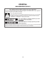
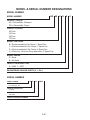
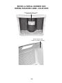
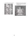
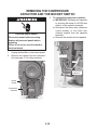
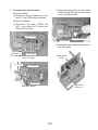
CONSUMER SERVICES TECHNICAL
EDUCATION GROUP PRESENTS
R-103
DEHUMIDIFIERS
Models: AD25BSS, AD35DSS, AD50DSS
Models: AD35USS, AD50USS, AD70USS
JOB AID
Part No. 8178563
FORWARD
This Whirlpool Job Aid, “Dehumidifier” (Part No. 8178563), provides the technician with information on the operation and service of the Dehumidifier. For specific information on the model being
serviced, refer to the “Use and Care Guide,” or “Wiring Diagram” provided with the dehumidifier.
The Wiring Diagrams used in this Job Aid are typical and should be used for training purposes
only. Always use the Wiring Diagram supplied with the product when servicing the unit.
GOALS AND OBJECTIVES
The goal of this Job Aid is to provide information that will enable the service technician to properly diagnose malfunctions and repair the dehumidifier.
The objectives of this Job Aid are to:
• Understand and follow proper safety precautions.
• Successfully troubleshoot and diagnose malfunctions.
• Successfully perform necessary repairs.
• Successfully return the dehumidifier to its proper operational status.
WHIRLPOOL CORPORATION assumes no responsibility for any repairs made
on our products by anyone other than Authorized Service Technicians.
Copyright © 2006, Whirlpool Corporation, Benton Harbor, MI 49022
- ii -
TABLE OF CONTENTS
Page
GENERAL . . . . . . . . . . . . . . . . . . . . . . . . . . . . . . . . . . . . . . . . . . . . . . . . . . . . . . . . . . . . . .
Dehumidifier Safety . . . . . . . . . . . . . . . . . . . . . . . . . . . . . . . . . . . . . . . . . . . . . . . . . . . . . .
Model & Serial Number Designations . . . . . . . . . . . . . . . . . . . . . . . . . . . . . . . . . . . . . . . .
Model & Serial Number And Wiring Diagram Label Locations . . . . . . . . . . . . . . . . . . . . .
1-1
1-1
1-2
1-3
PRODUCT OPERATION . . . . . . . . . . . . . . . . . . . . . . . . . . . . . . . . . . . . . . . . . . . . . . . . . . .
Theory Of Operation . . . . . . . . . . . . . . . . . . . . . . . . . . . . . . . . . . . . . . . . . . . . . . . . . . . . .
Dehumidifier Use . . . . . . . . . . . . . . . . . . . . . . . . . . . . . . . . . . . . . . . . . . . . . . . . . . . . . . . .
Dehumidifier Care . . . . . . . . . . . . . . . . . . . . . . . . . . . . . . . . . . . . . . . . . . . . . . . . . . . . . . .
2-1
2-1
2-4
2-8
COMPONENT ACCESS . . . . . . . . . . . . . . . . . . . . . . . . . . . . . . . . . . . . . . . . . . . . . . . . . . . 3-1
Component Locations . . . . . . . . . . . . . . . . . . . . . . . . . . . . . . . . . . . . . . . . . . . . . . . . . . . . 3-1
Removing The Cabinet . . . . . . . . . . . . . . . . . . . . . . . . . . . . . . . . . . . . . . . . . . . . . . . . . . . 3-2
Removing The Electronic Control, Thermistor, And Power Supply Cord . . . . . . . . . . . . . . 3-4
Removing The Mechanical Humidistat, Light, And Power Supply Cord . . . . . . . . . . . . . . 3-6
Removing The Fan Capacitor And The Fan Motor . . . . . . . . . . . . . . . . . . . . . . . . . . . . . . 3-8
Removing The Compressor Capacitor And The Bucket Switch . . . . . . . . . . . . . . . . . . . 3-10
COMPONENT TESTING . . . . . . . . . . . . . . . . . . . . . . . . . . . . . . . . . . . . . . . . . . . . . . . . . . .
Mechanical Humidistat . . . . . . . . . . . . . . . . . . . . . . . . . . . . . . . . . . . . . . . . . . . . . . . . . . .
Fan Capacitor & Compressor Capacitor . . . . . . . . . . . . . . . . . . . . . . . . . . . . . . . . . . . . . .
Fan Motor . . . . . . . . . . . . . . . . . . . . . . . . . . . . . . . . . . . . . . . . . . . . . . . . . . . . . . . . . . . . .
Bucket Switch . . . . . . . . . . . . . . . . . . . . . . . . . . . . . . . . . . . . . . . . . . . . . . . . . . . . . . . . . .
4-1
4-1
4-1
4-2
4-2
DIAGNOSTICS & TROUBLESHOOTING . . . . . . . . . . . . . . . . . . . . . . . . . . . . . . . . . . . . . . 5-1
Diagnostics . . . . . . . . . . . . . . . . . . . . . . . . . . . . . . . . . . . . . . . . . . . . . . . . . . . . . . . . . . . . 5-1
Troubleshooting . . . . . . . . . . . . . . . . . . . . . . . . . . . . . . . . . . . . . . . . . . . . . . . . . . . . . . . . . 5-2
WIRING DIAGRAMS . . . . . . . . . . . . . . . . . . . . . . . . . . . . . . . . . . . . . . . . . . . . . . . . . . . . . . 6-1
- iii -
— NOTES —
- iv -
GENERAL
DEHUMIDIFIER SAFETY
Your safety and the safety of others are very important.
We have provided many important safety messages in this Manual and on your appliance.
Always read and obey all safety messages.
This is the safety alert symbol.
This symbol alerts you to potential hazards that can kill or hurt you and others.
All safety messages will follow the safety alert symbol and either the word
“DANGER” or “WARNING.” These words mean:
DANGER
You can be killed or seriously injured if you don’t
immediately follow instructions.
You can be killed or seriously injured if you don’t
follow instructions.
All safety messages will tell you what the potential hazard is, tell you how to reduce the chance
of injury, and tell you what can happen if the instructions are not followed.
1-1
MODEL & SERIAL NUMBER DESIGNATIONS
MODEL NUMBER
AD 50 U S
MODEL NUMBER
PRODUCT GROUP
AD = Dehumidifier, Whirlpool
RD = Dehumidifier, Roper
CAPACITY (24 HR.)
25 Pints
35 Pints
50 Pints
70 Pints
MODEL FEATURES
B = Electromechanical, No Deicer, 1 Speed Fan
C = Electromechanical, Std. Deicer, 1 Speed Fan
D = Electromechanical, Std. Deicer, 2 Speed Fan
U = Electronic, Ultra-Low Temp Application, 2 Speed Fan
MODEL SERIES
S = Estar
B = No Estar
YEAR OF INTRODUCTION
S = 2006, T = 2007
ENGINEERING CHANGE DIGITS (0, 1, Etc.)
SERIAL NUMBER
SERIAL NUMBER
Q
S
21
00043
MANUFACTURING SITE
Q = LaVergne, TN
YEAR OF PRODUCTION
S = 2005
WEEK OF PRODUCTION
21st Week
PRODUCT SEQUENCE NUMBER
1-2
S
0
MODEL & SERIAL NUMBER AND
WIRING DIAGRAM LABEL LOCATIONS
Model & Serial Number Label
(Behind Water Bucket)
Wiring Diagram Label
(Inside Front Half Of Cabinet)
1-3
— NOTES —
1-4
PRODUCT OPERATION
THEORY OF OPERATION
WHAT IS HUMIDITY?
REMOVING UNWANTED HUMIDITY
Humidity is defined as the amount of water vapor in the air and is measured as a percentage
of the amount of water vapor the air can hold
at a given temperature. When the amount of
water vapor exceeds 100%, the moisture can
no longer remain suspended in the air, usually
resulting in precipitation. At levels approaching
100%, mist and fog are present.
Generally speaking, air at low temperatures
has less holding capacity than air at high temperatures. Therefore, air with 100% humidity
at 45°F has less water vapor by volume than
air with 100% humidity at 70°F. Consequently,
summer months throughout most of the country
can present a problem, because warm moist air
trapped inside a structure can become overly
saturated with moisture. Generally, humidity
levels exceeding 50% in air over 70°F, can
be uncomfortable and can cause damage to
personal property.
A dehumidifier is designed to remove unwanted
moisture from the air and maintain relative
humidity at acceptable levels. A dehumidifier
does not remove all of the moisture from the
air, as this is not necessary, or desirable. The
dryness control on the dehumidifier allows the
customer to adjust a variable humidistat to
control the relative humidity of room air. Once
the humidistat is set to maintain acceptable
humidity levels in a room, the dehumidifier will
continue to maintain that level, regardless of
the ambient temperature of the air, or changes
in relative humidity
A refrigeration system (see the illustration below) is used to collect the moisture. With the
refrigeration system working, the evaporator is
cooled to temperatures ranging from 33° - 37°F.
When moisture-ladened room temperature air
is drawn across the evaporator, the moisture
condenses on the cold coils. The cool dry air
is then drawn past the condenser. This cools
the condenser and warms the air before it is
recirculated into the room. The water collected
on the coils of the evaporator runs off into a
collection container, or a drain.
SUCTION TUBE
DISCHARGE TUBE
EVAPORATOR
CONDENSER
AIR
FLOW
(IN)
AIR
FLOW
(OUT)
FAN
COLLECTED WATER
2-1
CAPILLARY TUBE
OPERATING CHARACTERISTICS
LOW TEMPERATURE OPERATION
When a dehumidifier begins its run cycle, a
partial frosting of the evaporator can be observed. This temporary frosting is limited by the
operating conditions of the unit. In all cases,
the frost should completely disappear within
10 to 15 minutes.
In cool dry conditions, (65°F or lower temperatures, and relative humidity of 60% or less), the
evaporator may become completely coated
with frost or ice. Under these conditions, the
evaporator temperature is reduced to below
freezing (32°F) because of inadequate heat
load, and it is possible that no moisture will
be collected from the air. Mechanical control
dehumidifiers without a deicer thermostat are
not designed to operate under these conditions, and the customer should be advised to
discontinue use until proper ambient conditions
are present.
Mechanical control models without a deicer
thermostat, i.e. AD25BSS, must not be operated below 65°F. Mechanical control models
with a deicer thermostat, i.e. AD35DSS, may
be operated as low as 55°F.
Electronic control models, i.e. AD35USS,
monitor the temperature of the evaporator using a thermistor and may be operated as low
as 38°F.
When the thermistor reaches 30°F, the control
begins timing. After 10 minutes at or below
30°F, the compressor is turned off. The fan
continues to run for a period of 10 minutes
before the compressor is restarted. This low
temperature operation will continue until the
thermistor reaches 40°F for 20 minutes.
ELECTRONIC CONTROL SENSORS
• The humidistat is an electronic version of
the mechanical humidistat. It monitors the
relative humidity of the room air.
• The thermistor is a device that changes resistance as the temperature changes. The
electronic control monitors the resistance
and operates the compressor and fan motor
accordingly.
TYPICAL OPERATION
The control panel (see below) provides the
customer with control over the speed of the fan,
(when this feature is offered), and adjustment
of the amount of moisture in the air. An indicator light also provides information on the water
level in the bucket, and whether the bucket is
properly installed in the unit.
A
DEFECTIVE SENSOR DEFAULT
B
If either the thermistor or the humidistat fails
on electronic control models, the control will
operate in the following manner.
• The compressor cycles on for 25 minutes
and off for 10 minutes.
• The fan operates continuously at the set
speed or High if set to Auto mode.
A. Light glows, indicating the bucket is full or is not in correct position.
B. Adjusts amount of moisture removed from room.
A
C
B
A. Light glows, indicating the bucket is full or is not in correct position.
B. Adjusts amount of moisture removed from room.
C. Selects fan speed.
2-2
FAN SPEED: Controls the fan operation, as
follows:
High: For faster moisture removal
Low: For slower moisture removal
Auto Fan Speed (Electronic Models):
Automatically sets the fan speed based on
the relative humidity of the room. Low speed
is used when the relative humidity is within
5% of the Desired Humidity setting. High
speed is used when the relative humidity
reaches or exceeds 5% of the Desired
Humidity setting.
on. If the relative humidity has not increased,
the unit will only run for 3 minutes. There is a
3 minute minimum “on” or “off” time used to
protect the compressor that requires at least
3 minutes of run time or off time before the
compressor stops or restarts.
The reason for the compressor to be turned on
30 minutes after it cycles off is that when the
unit cycles off, heat from the condenser and fan
motor rises up toward the control. This higher
temperature lowers the relative humidity around
the humidistat and the unit will not run even if
the relative humidity in the room is rising. This
assures the room relative humidity is properly
monitored. The unit will not cycle off and on
when set to continuous run.
ADJUST/EMPTY BUCKET LIGHT: When
this light is “ON,” it indicates that the unit is
not running (see “Setting The Controls, Types
1, 2, or 3 on Pages 2-4 and 2-5). Look for the
following conditions:
DRYNESS CONTROL: Controls the amount
of moisture in the room. Set the control to the
normal setting to maintain average humidity
conditions. Adjust the control to a higher or
lower setting for more or less drying.
When the dehumidifier is first installed, the
customer may wish to set the Dryness Control
to the DRYER setting to remove extra moisture
from furnishings, as well as the room air.
• The bucket is full: Empty the bucket
and replace it in the dehumidifier.
• The bucket is not correctly installed
in the unit: Remove and replace the
bucket in the unit so that it fits all the
way in. Make sure the light is off, or the
dehumidifier will not run.
When the humidistat senses the desired humidity level has been reached, the control
cycles off the compressor and fan motor. On
electronic control models, 30 minutes after the
unit cycles off at the desired relative humidity,
the compressor and fan will be cycled back
2-3
DEHUMIDIFIER USE
SETTING THE CONTROLS
(CONTROL TYPES 1 & 2 ONLY)
Starting/Stopping the Dehumidifier
NOTE: Before turning on the dehumidifier, be
sure that the bucket is empty and fits all the
way into the dehumidifier.
Control Type 1
NOTE: Minimum operating temperature is
65ºF (18ºC).
A
Electrical Shock Hazard
Plug into a grounded 3 prong outlet.
Do not remove ground prong.
Do not use an adapter.
Do not use an extension cord.
Failure to follow these instructions can
result in death, fire, or electrical shock.
B
1. Plug into a grounded 3 prong outlet.
2. To turn on dehumidifier, turn DRYNESS
CONTROL clockwise.
IMPORTANT: If the Empty/Adjust Bucket
light comes on, the dehumidifier will not
operate. Empty or adjust bucket.
3. To turn off dehumidifier, turn DRYNESS
CONTROL counterclockwise to OFF.
A. Light glows, indicating the bucket is full or is not in correct position.
B. Adjusts amount of moisture removed from room.
Control Type 2
NOTE: Minimum operating temperature is
55ºF (13ºC).
A
Empty/Adjust Bucket Light
If this light is on, the dehumidifier is not running.
This light indicates that you need to check:
• If the bucket is full, empty and reinstall
bucket.
• If the bucket is not in position, remove the
bucket and reinstall. Make sure the bucket
fits all the way into the dehumidifier and the
light is off, or dehumidifier will not run.
B
Fan Speed (Control Type 2 Models Only)
The Fan Speed controls fan operation
• High—for faster moisture removal
• Low—for quieter moisture removal
C
A. Light glows, indicating the bucket is full or is not in correct position.
B. Adjusts amount of moisture removed from room.
C. Selects fan speed.
2-4
Dryness Control
The Dryness Control regulates the amount of
moisture in the room. Turn the control knob
clockwise for more drying. Turn the control
knob counterclockwise for less drying. Turn
the control knob to “Dry” to maintain average
humidity conditions.
NOTE: For the first few days of use, turn the
DRYNESS CONTROL clockwise to CONTINUOUS RUN to remove extra moisture from the
furnishings as well as the room air.
Electrical Shock Hazard
Plug into a grounded 3 prong outlet.
Do not remove ground prong.
Do not use an adapter.
Do not use an extension cord.
Failure to follow these instructions can
result in death, fire, or electrical shock.
SETTING THE CONTROLS
(CONTROL TYPE 3 ONLY)
Starting/Stopping the Dehumidifier
NOTES:
• Before turning on the dehumidifier, be sure
that the bucket is empty and fits all the way
into the dehumidifier.
• Each time you unplug the dehumidifier or
power is interrupted, the control will return
to your previous settings when power is
restored.
1. Plug into a grounded 3 prong outlet.
2. Press POWER to turn on dehumidifier.
IMPORTANT: If the Empty/Adjust Bucket
light comes on, the dehumidifier will not
operate. Empty or adjust bucket.
3. Press POWER to turn off dehumidifier.
NOTE: The dehumidifier will retain your last
settings.
Control Type 3
NOTE: Minimum operating temperature is
38°F (3°C).
Empty/Adjust Bucket Light
If this light is on, the dehumidifier is not running.
This light indicates that you need to check:
• If the bucket is full, empty and reinstall
bucket.
• If the bucket is not in position, remove the
bucket and reinstall. Make sure the bucket
fits all the way into the dehumidifier and the
light is off, or dehumidifier will not run.
A
C
Fan Speed (Control Type 3 Models Only)
1. Press FAN to select fan speed.
2. Choose Low, High or Auto.
• Low—Will reach the desired humidity
setting slower with lower sound level.
• High—Will reach the desired humidity
setting faster.
B
A. Light glows, indicating the bucket is full or is not in correct position.
B. Adjusts amount of moisture removed from room.
C. Selects fan speed.
2-5
DRAINING THE DEHUMIDIFIER
• Auto —Will provide the maximum humidity control by automatically adjusting the
fan speed and/or turning the dehumidifier
on and off to maintain humidity setting.
Desired Humidity (Control Type 3 Models
Only)
1. Press DESIRED HUMIDITY to select the
desired humidity setting.
2. Choose Normal, Dry, Max Dry or Continuous Run.
• Normal—Will operate the dehumidifier at
the selected fan speed until the humidity
levels are lowered.
• Dry—Will operate the dehumidifier at
the selected fan speed until the humidity
levels are lowered more than the Normal
setting.
• Max Dry—Will operate the dehumidifier
at the selected fan speed until the humidity levels are lowered to the maximum
level.
• Continuous Run—Will operate the dehumidifier continuously at the selected fan
speed regardless of humidity level.
If Auto fan speed is selected, the fan will
operate at the High speed setting. The
dehumidifier will turn off only if the bucket
is full or removed.
NOTE: The Deicer will turn off the compressor if a low temperature condition
exists. Pressing the Desired Humidity
arrow will not increase or decrease the
amount of moisture removed. Compressor operation will resume when the low
temperature condition no longer exists.
Sickness Hazard
Do not drink water collected in water
bucket.
Doing so can result in sickness.
Option 1—Remove Bucket
If a floor drain is not available, or you do not
plan to run the dehumidifier continuously, you
may want to simply empty the bucket.
1. Use front handle to slide bucket out.
2. Use front and back handles to lift bucket.
2-6
3. Pour water through opening into a sink or
tub.
3. Attach a garden hose to drain hose connector on the inside of the dehumidifier. Hand
tighten.
A
B
A. Garden hose
B. Drain hose connector
4. Place the other end of garden hose into a
floor drain. Check to see that the hose lies
flat and is in the drain.
5. Reinstall bucket.
4. Reinstall bucket.
IMPORTANT: If the Empty/Adjust Bucket
light comes on, the dehumidifier will not
operate. Empty or adjust bucket.
Option 2—Connect Drain Hose
If you plan to run your dehumidifier continuously, you may want to attach a garden hose
to the drain hose connector.
1. Use a flat-blade screwdriver to gently pry
out the drain hose connector cover. Discard
the cover.
A
NOTES:
• To use the bucket without the garden hose,
remove the garden hose. Then reinstall
bucket.
• The bucket must be installed and properly
aligned for the dehumidifier to operate with
or without a garden hose connected.
NORMAL SOUNDS
When your dehumidifier is operating normally,
you may hear sounds such as:
• Compressor sounds, which may be loud.
This is normal.
• Clicking sounds when the dehumidifier or
compressor turns off and on, and when the
Automatic Shutoff Switch is working.
B
A. Drain hose connector cover
B. Bucket
2. Remove bucket.
• Air movement from the fan.
2-7
DEHUMIDIFIER CARE
CLEANING THE AIR FILTER
(ON SOME MODELS)
CLEANING THE DEHUMIDIFIER
Exterior
NOTE: Have an authorized service technician
clean and service the interior coils of your
product annually.
1. Turn off dehumidifier.
2. Dust front grille and side panels with a soft
brush or the dusting attachment of your
vacuum cleaner.
The air filter is removable for easy cleaning. A
clean filter helps remove dust, lint, and other
particles from the air and is important for best
operating efficiency. Check the filter every 2
weeks to see whether it needs cleaning.
1. Turn off dehumidifier.
2. Remove bucket.
3. Pull filter down from below front louvers.
Water Bucket
Every few weeks, rinse the inside of the water
bucket with a mild detergent to avoid growth
of mold, mildew and bacteria.
Water Level Float
The dehumidifier has an Empty/Adjust Bucket
light and a water level float. The bucket must
be properly aligned for the water level float and
Empty/Adjust Bucket light to work.
NOTE: Be sure float is snapped in place.
4. Pull bottom edge of air filter toward you to
clear the bottom of the dehumidifier.
A
B
A. Water level float
B. Bucket
5. Use a vacuum cleaner to clean air filter. If air
filter is very dirty, wash it in warm water with
a mild detergent. Do not wash air filter in the
dishwasher or use any chemical cleaners.
Air dry filter completely before replacing to
ensure maximum efficiency.
6. Slide air filter up into the dehumidifier.
7. Reinstall bucket.
8. Turn on the dehumidifier.
2-8
COMPONENT ACCESS
This section instructs you on how to service the Dehumidifier. The components and their locations are shown below. NOTE: The sealed system in the Dehumidifier is not serviced.
COMPONENT LOCATIONS
Electrical Shock Hazard
Disconnect power before servicing.
Replace all parts and panels before operating.
Failure to do so can result in death or electrical shock.
REAR COMPONENTS
FRONT COMPONENTS
Electronic
Control
Humidistat
Fan Capacitor
Thermistor
Fan Motor
Bucket Switch
Compressor
Capacitor
Power Supply
Cord
Electronic Control Unit Shown
3-1
REMOVING THE CABINET
3.
4.
If present, pull the air filter down and out
from behind the front louvers.
Remove the two front screws from the
front half of the cabinet.
Electrical Shock Hazard
Disconnect power before servicing.
Replace all parts and panels before
operating.
Failure to do so can result in death or
electrical shock.
Air
Filter
Front Screws
1.
2.
Unplug dehumidifier or disconnect power.
Pull the water bucket out of the dehumidifier and remove it.
5.
Remove the screw from the left and right
side of the cabinet.
Water Bucket
Left Side Screw
3-2
6.
Remove the bottom screw and the two
top hex-head screws from the rear half of
the cabinet.
7.
Pull the front and rear halves of the cabinet from the dehumidifier and remove
them.
Top Rear Screws
Rear Half
Bottom Rear Screw
3-3
Front Half
REMOVING THE ELECTRONIC CONTROL,
THERMISTOR, AND POWER SUPPLY CORD
3.
Disconnect the four wire connectors from
the electronic control.
Electronic
Control
Electrical Shock Hazard
Disconnect power before servicing.
Replace all parts and panels before
operating.
Failure to do so can result in death or
electrical shock.
1.
2.
Unplug dehumidifier or disconnect power.
Remove the cabinet from the dehumidifier (see page 3-2 for the procedure).
NOTE: The electronic control, thermistor, and
power supply cord are hard-wired together
and are serviced as an assembly.
Black (Compressor)
Orange
Black (Fan Motor)
4.
Remove the two hex-head screws from
the electronic control.
Electronic
Control
Thermistor
Electronic Control Screws
Power
Supply
Cord
Front View
Bucket Switch
Power Supply Cord
Rear View
3-4
White
5.
6.
Unclip the thermistor from the tubing and
remove it. NOTE: Do not remove the
thermistor from the clip.
Remove the hex-head screw from the
green ground wire.
9.
Remove the power supply cord from the
cabinet.
Power Supply Cord
Thermistor & Clip
10. Remove the wiring from the three tabs,
and remove the electronic control assembly from the dehumidifier.
Ground Wire Screw
7.
8.
On the rear of the unit, disconnect the
two wires from the bucket switch terminals and unclip the wires.
Disconnect the indicated white control wire
from the compressor capacitor terminal.
Wire
Tabs
Bucket Switch Wires
White Control Wire
Compressor
Capacitor
Electronic Control Assembly
3-5
REMOVING THE MECHANICAL HUMIDISTAT,
LIGHT, AND POWER SUPPLY CORD
5.
Electrical Shock Hazard
Disconnect power before servicing.
Replace all parts and panels before
operating.
Failure to do so can result in death or
electrical shock.
1.
2.
3.
4.
Unsnap the four top cover tabs from the
mechanical control and remove the cover.
Top Cover Tabs
Unplug dehumidifier or disconnect power.
Remove the cabinet from the dehumidifier (see page 3-2 for the procedure).
Pull the knob off the humidistat shaft.
Remove the two hex-head screws from
the control.
Humidistat Knob
6.
To remove the mechanical humidistat:
a) Disconnect the brown wire and the
connector with the two black wires
from the mechanical humidistat terminals.
b) Unclip the humidistat from the cover
and remove it.
7.
To remove the light:
a) Disconnect the yellow and two white
wires from the light terminals.
b) Unclip the light from the cover and remove it.
YL
2 WH
Mechanical Control Screws
2 BK
BN
Mechanical Humidistat
3-6
Light
8.
To remove the power supply cord:
a) Disconnect the white power supply
cord wire from the compressor capacitor terminal.
b) Disconnect the black power supply
cord wire from the COM terminal of
the bucket switch.
c) Remove the hex-head screw from the
green ground wire at the top of the
condenser.
Bucket Switch
Condenser
BK (COM) Wire
WH Wire
Ground Wire Screw
Compressor
Capacitor
d) Remove the power supply cord from
the dehumidifier.
Power Supply Cord
3-7
REMOVING THE FAN CAPACITOR AND THE FAN MOTOR
4.
Brown Wires
Electrical Shock Hazard
Disconnect power before servicing.
Replace all parts and panels before
operating.
Failure to do so can result in death or
electrical shock.
1.
2.
To remove the fan motor:
a) Loosen the T-20 Torx screw and pull
the blower off the fan motor shaft.
Capacitor Screw
Unplug dehumidifier or disconnect power.
Remove the cabinet from the dehumidifier (see page 3-2 for the procedure).
Blower Clamp Screw
Fan
Capacitor
b) Disconnect the fan motor wires at the
following locations:
• Two brown wires from the fan capacitor terminals (see above).
• Electronic Models: Black, orange,
and white wires from the electronic
control terminals (see page 3-4).
• Mechanical Type 1 Models: Black
and white wires from the humidistat
and light terminals (see page 3-6).
• Mechanical Type 2 Models: Black
and orange wires from the fan
switch terminals (not shown). White
wire from the light terminal.
Fan Motor
3.
To remove the fan capacitor (see the
top right photo):
a) IMPORTANT: Discharge the capacitor
by touching the leads of a 20,000 ohm
resistor to the capacitor terminals.
b) Disconnect the two wires from the capacitor terminals.
c) Remove the screw from the capacitor.
3-8
• Top green ground wire on condenser.
c) Remove the three 5/16˝ hex-head
screws from the fan motor, then pull
the wiring out of the access hole and
remove the motor.
Top Ground
Wire Screw
Condenser
Fan Motor Screws
3-9
REMOVING THE COMPRESSOR
CAPACITOR AND THE BUCKET SWITCH
3.
Electrical Shock Hazard
Disconnect power before servicing.
Replace all parts and panels before
operating.
To remove the compressor capacitor:
a) IMPORTANT: Discharge the capacitor
by touching the leads of a 20,000 ohm
resistor to the capacitor terminals.
b) Disconnect the three wires (electronic
control models), or four wires (mechanical models) from the capacitor
terminals.
c) Remove the screw from the capacitor.
Failure to do so can result in death or
electrical shock.
1.
2.
Unplug dehumidifier or disconnect power.
Remove the cabinet from the dehumidifier (see page 3-2 for the procedure).
WH Wires
Screw
YL Wire
Bucket
Switch
Compressor
Capacitor
3-10
Compressor
Capacitor
4.
To remove the bucket switch:
Electronic Model:
a) Disconnect the two black wires from
the N.C. and COM switch terminals.
c) Press the locking tab, push the switch
holder through the cutout, and remove
it from the dehumidifier.
Mechanical Models:
b) Disconnect the black (COM), tan
(N.O.), and yellow (N.C.) wires from
the switch terminals.
Bucket Switch
Switch Holder
Press Tab & Push In
d) Unclip the bucket switch and remove it
from the holder.
BK (N.C.)
BK (COM)
Bucket Switch
Holder
Electronic Model
YL (N.C.)
Bucket Switch
TN (N.O.)
BK (COM)
Unclip Switch
To Remove
Mechanical Models
3-11
— NOTES —
3-12
COMPONENT TESTING
• Check all connections before replacing
components, looking for broken or loose
wires, failed terminals, or wires not pressed
into connectors far enough.
• Resistance checks must be made with
power cord unplugged from outlet, and
with wiring harness or connectors discon-
Before testing any of the components, perform the following checks:
• The most common cause for control failure
is corrosion on connectors. Therefore, disconnecting and reconnecting wires will be
necessary throughout test procedures.
• All tests/checks should be made with a
VOM or DVM having a sensitivity of 20,000
ohms-per-volt DC, or greater.
Electrical Shock Hazard
Disconnect power before servicing.
Replace all parts and panels before operating.
Failure to do so can result in death or electrical shock.
MECHANICAL HUMIDISTAT
Control
FAN CAPACITOR &
COMPRESSOR CAPACITOR
Terminals
Refer to pages 3-8 and 3-10 for the procedures for accessing the fan capacitor and the
compressor capacitor.
1. Unplug dehumidifier or disconnect power.
2. IMPORTANT: Discharge the capacitor by
touching the leads of a 20,000 ohm resistor to the capacitor terminals.
3. Disconnect the wires from the capacitor
terminals.
4. Set the ohmmeter to the R x 1K scale.
5. Touch the ohmmeter test leads to the capacitor terminals. The meter should indicate several ohms, and gradually return
to infinity.
Refer to page 3-6 for the procedure for accessing the mechanical humidistat.
1. Unplug dehumidifier or disconnect power.
2. Disconnect the two wires from the humidistat terminals.
3. Turn the humidistat control fully counterclockwise.
4. Set the ohmmeter to the R x 1 scale.
5. Touch the ohmmeter test leads to the humidistat terminals. The meter should indicate an open circuit (infinite).
6. Turn the humidistat control clockwise until you hear it click. The meter should indicate a closed circuit (0 Ω).
4-1
Electrical Shock Hazard
Disconnect power before servicing.
Replace all parts and panels before operating.
Failure to do so can result in death or electrical shock.
FAN MOTOR
BUCKET SWITCH
Actuator
N.C.
N.O.
Refer to page 3-8 for the procedure for accessing the fan motor.
1. Unplug dehumidifier or disconnect power.
2. IMPORTANT: Discharge the capacitor by
touching the leads of a 20,000 ohm resistor to the capacitor terminals.
3. Disconnect the fan motor wires from the
capacitor terminals.
4. Disconnect the remaining fan motor wires
from the mechanical or electronic control
terminals.
5. Set the ohmmeter to the R x 1 scale.
6. Touch the ohmmeter test leads to the indicated motor wire connectors. The meter
should indicate as shown in the following
chart:
Motor
Motor Capacity
Part #
Type
(Pints)
1188409 1-Speed
25
2-Speed 35 & 50
1188411 2-Speed 35 & 50
2-Speed
70
1188413 2-Speed
70
Test
Lead
Wh-Bk
Wh-Or
Wh-Bk
Wh-Or
Wh-Bk
COM
Refer to page 3-10 for the procedure for accessing the bucket switch.
1. Unplug dehumidifier or disconnect power.
2. Disconnect the wires from the bucket
switch terminals.
3. Set the ohmmeter to the R x 1 scale.
4. Touch the ohmmeter test leads to the
indicated switch terminals. The meter
should indicate as follows:
COM and N.C. = 0 Ω
COM and N.O. = Infinite
5. Press the actuator and the readings in
step 4 should reverse:
COM and N.C. = infinite
COM and N.O. = 0 Ω
Resistance
(Ohms)
161 ±20%
142 ±20%
118 ±20%
65 ±20%
50 ±20%
4-2
DIAGNOSTICS & TROUBLESHOOTING
DIAGNOSTICS
1. Turn off the dehumidifier with the power
button.
• If you press a wrong key during the 3-key
sequence, or if more than 5 seconds elapses before completing the sequence, you
will need to restart the sequence from the
beginning.
• After pressing the 3 keys in the correct
order within 5 seconds, all the LEDs
will light at Step 1 (see chart). Use
the Desired Humidity key to advance
the steps. Using any other key will exit
diagnostics.
2. Remove the bucket.
3. Unplug the dehumidifier for at least 1 second.
4. Reconnect power.
5. Within 5 seconds of restoring power, complete the following 3-key entry sequence
in this order: Desired Humidity, Fan, and
Power.
IMPORTANT: If you do not complete the
diagnostics procedure within 15 minutes, the
control will exit the diagnostics.
Step
1
2a
2b
2c
3
4
5
Test
LEDs
LED Name
All
LED Condition
All illuminate
Blinking= Bucket
removed (switch open)
Bucket switch
Bucket
ON solid= Bucket
installed (switch closed)
On solid= Pass
Thermistor
Normal
Blinking= Fail
Continuous
On solid= Pass
Humidistat
run
Blinking= Fail
ON solid,
HIGH speed fan
HIGH
confirm operation
ON solid,
LOW speed fan
LOW
confirm operation
ON solid,
Compressor
AUTO
confirm operation
(On for 20 seconds)
Exit
5-1
TROUBLESHOOTING
Electrical Shock Hazard
Disconnect power before servicing.
Replace all parts and panels before operating.
Failure to do so can result in death or electrical shock.
PROBLEM
Unit will not run - no fan
and no compressor.
Fan runs - compressor
does not run.
CAUSE
CORRECTION
1. Unit not turned “ON” or not set dry
enough.
1. Set control to “CONTINUOUS.” This will allow the fan and compressor to run regardless of the ambient humidity.
2. No power to unit.
2a. Power supply cord not plugged in. Plug in cord.
2b. Unit plugged into outlet that has no power to it (blown fuse or
tripped circuit breaker). Advise customer to correct this problem
with a qualified electrician.
3. Bucket In/Water Level switch open.
3a. Empty bucket.
3b. Make sure bucket is installed properly.
3c. Check switch. Replace, if defective.
4. Defective power supply cord or loose
wiring in unit.
4. Check wiring and supply cord. Repair or replace defective parts.
5. Defective humidistat.
5. Run diagnostics. Replace electronic control, if needed.
1. Mechanical Models: Deicer thermostat 1a. Let evaporator coil thaw. Normal if coil is frosted over.
open.
1b. Replace deicer thermostat if it is still open after coil thaws and
warmed up.
2. Electronic Models: Thermistor out of
2a. Unit in defrost mode. Raise room temperature.
range or evaporator is less than 30°F. 2b. Run diagnostics. Replace electronic control, if needed.
3. Compressor overload or relay defective. 3. Check both components and replace, if defective.
Fan does not run compressor runs.
4. Compressor windings open.
4. Check continuity and replace if one or both windings are open.
1. Fan motor not getting power.
1. Check wiring. Repair or replace, as necessary.
2. Fan motor defective.
2. Replace fan motor.
3. Fan blade jammed.
3. Remove obstruction. Replace if fan blade is damaged.
Fan and compressor run - 1. Ambient room temperature is too cold 1. Turn unit off until room temperature reaches 65°F (18.3°C).
evaporator coil frosted over.
(non deicer model).
Fan and compressor run no dehumidification.
1. Unit out of refrigerant.
1. Follow sweep charge procedure to find and repair leaks.
2. Humidity too low.
2. Turn unit off until humidity goes up.
3. Dirty evaporator or blocked air filter.
3. Clean air filter and/or evaporator.
1. Area is not sealed off - open doors and/ 1. Isolate area by closing doors and windows.
or windows.
Unit runs - insufficient
dehumidification.
2. Grilles obstructed.
2. Move unit or items so grilles are not blocked.
3. Dirty evaporator or blocked air filter.
3. Clean air filter and/or evaporator.
4. Low refrigerant charge.
4. Follow sweep charge procedure to find and repair leaks.
5. Unit too small for area being
dehumidified.
5. Close off into smaller area.
5-2
WIRING DIAGRAMS
WIRING DIAGRAM 1
6-1
WIRING DIAGRAM 2
6-2
WIRING DIAGRAM 3
6-3
— NOTES —
6-4
— NOTES —
6-5
— NOTES —
6-6
PRODUCT SPECIFICATIONS
AND
WARRANTY INFORMATION SOURCES
IN THE UNITED STATES:
FOR PRODUCT SPECIFICATIONS AND WARANTY INFORMATION CALL:
FOR WHIRLPOOL PRODUCTS: 1-800-253-1301
FOR KITCHENAID PRODUCTS: 1-800-422-1230
FOR ROPER PRODUCTS: 1-800-447-6737
FOR TECHNICAL ASSISTANCE WHILE AT THE CUSTOMER’S HOME CALL:
THE TECHNICAL ASSISTANCE LINE: 1-800-253-2870
HAVE YOUR STORE NUMBER READY TO IDENTIFY YOU AS AN
AUTHORIZED SERVICER
FOR LITERATURE ORDERS:
PHONE: 1-800-851-4605
FOR TECHNICAL INFORMATION AND SERVICE POINTERS:
www.servicematters.com
IN CANADA:
FOR PRODUCT SPECIFICATIONS AND WARRANTY INFORMATION CALL:
1-800-461-5681
FOR TECHNICAL ASSISTANCE WHILE AT THE CUSTOMER’S HOME CALL:
THE TECHNICAL ASSISTANCE LINE: 1-800-488-4791
HAVE YOUR STORE NUMBER READY TO IDENTIFY YOU AS AN
AUTHORIZED SERVICER
CORPORATION