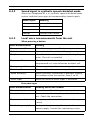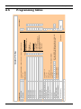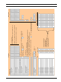
1
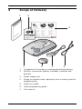
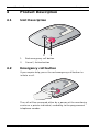
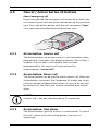
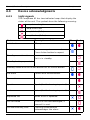
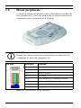
Carephone 61
CRS-H61M-xx
en
User Manual
Carephone 61
Table of Contents | en
3
Table of Contents
1
Safety Instructions
5
2
Features
6
3
Scope of Delivery
7
4
Product Description
8
4.1
Unit Description
8
4.2
Emergency call button
8
4.3
Cancel / Action button (S button)
9
4.3.1
Action button: Service call
9
4.3.2
Action button: Direct call
9
4.3.3
Action button: Unit status
9
4.4
Device acknowledgments
10
4.4.1
Light signals
10
4.4.2
Sound signal in synthetic speech disabled mode
11
4.4.3
Local voice announcements from the unit
11
5
Installation
12
5.1
Installation recommendations
12
5.2
Placing the Carephone 61
12
5.3
Connecting the Carephone 61
13
5.3.1
PSTN or GSM connection
13
5.3.2
IP connection
14
5.3.3
VoIP connection
14
5.3.4
Connection configuration
14
5.4
Deinstallation
14
6
Programming
15
6.1
Programming methods
15
6.2
Programming procedure
16
6.2.1
Opening the unit and access the keyboard
16
6.2.2
Entering keyboard programming
16
6.2.3
Key functions during keyboard programming
17
6.2.4
Programming steps
17
Bosch Security Systems
User Manual
F.01U.239.30x | V1 | 2011.06
4
en | Table of Contents
Carephone 61
6.2.5
Special key functions
26
6.3
Test instructions
26
7
Additional Devices
27
7.1
Wireless transmitters
27
7.2
Wireless detectors
27
7.3
Wired peripherals
28
7.4
Microphone and loudspeaker connection
29
7.5
microSD memory card
29
7.5.1
Installing the microSD memory card
30
7.5.2
Programming with the microSD memory card
32
8
Operation
34
8.1
Emergency Call to a Monitoring Centre
34
8.2
Emergency Call to a Private Phone
34
8.3
Taking Phone Calls
36
9
Maintenance
37
9.1
Cleaning
37
9.2
Battery disposal
37
9.3
Replacing the backup battery
38
A
Appendix
42
A.1
Technical specifications
42
A.2
Conformity
44
A.3
Wall mounting
44
A.4
Drilling template
46
A.5
Programming tables
48
Index
50
F.01U.239.30x | V1 | 2011.06
User Manual
Bosch Security Systems
Carephone 61
1
Safety Instructions | en
5
Safety Instructions
CAUTION!
Read through the safety instructions carefully before using the
unit for the first time. This is important for connection, use and
safety.
–
Do not install the unit near a heating appliance.
–
Do not expose the unit to direct sunlight.
–
Do not install in a wet or humid environment.
–
Never touch the power adapter with wet hands.
–
Do not attempt to open the unit or the power adapter.
–
When unplugging the unit from the power outlet, never
pull on the power cord but always grip the power adapter.
–
Connect the Carephone 61 only to a professionally
installed 230 V AC/50 Hz power outlet with a 10 A fuse.
–
Do not install the Carephone 61 in the proximity of DECT/
GSM telephones, TV sets, large metal objects, microwave
appliances or radio telephones. This will impair the
reception of signals from the wireless transmitter.
–
Use only original equipment for cables and power supply.
–
Electrolytes or gases may be emitted from the battery
Any other power adapter could damage the unit.
should it leak under exceptional circumstances. If this
happens, deactivate the unit by isolating it from the phone
network and power supply. Battery replacement must be
carried out by trained service personnel only.
Electrostatic Discharge
WARNING!
The Carephone 61 contains highly sensitive electronic
components. It should be opened only in an ESD protected
environment with respect to the following precautions.
Discharge yourself from electrostatic loads by touching a
grounded conductive surface before opening the unit.
Bosch Security Systems
User Manual
F.01U.239.30x | V1 | 2011.06
6
2
en | Features
Carephone 61
Features
The Carephone 61 has been designed to ensure maximum
security for persons living in their own homes. It can be used to
send emergency calls to a receiver or a telephone.
The person requiring assistance activates a call by pressing a
button on the Carephone 61 or by using a wireless transmitter.
This action establishes a voice connection between the person
requiring assistance and the call receiver.
The device has two basic operating modes:
1.
The Carephone 61 is part of a social alarm system that
consists of a monitoring centre that can be reached at any
time and the Carephone itself. Calls are sent to this
monitoring centre.
2.
The unit is operated as a standalone unit, in which case
emergency calls will be sent to private phones.
The Carephone 61 provides connections for an external
microphone and an external loudspeaker, as well as wired input
and output, and a microSD memory card. It can be used with up
to 10 wireless transmitters. A signaling device can also be
connected for individuals with speech/hearing difficulties.
microSD Logo is a trademark of SD-3C, LLC.
F.01U.239.30x | V1 | 2011.06
User Manual
Bosch Security Systems
Carephone 61
3
Scope of Delivery | en
7
Scope of Delivery
7
6
1
e6
n
ho
p
re
Ca
EN
1
2
3
4
3
6
7
rM
e
Us
u
an
Carephone 61
8
Emergency call
Alarma de colgante
Llamada de asistencia
Anular llamada
FR
Médaillon d'urgence
Appel d’urgence
Annuler l’alarme
NL
Handzender alarm
9
Alarmoproep
Alarm stoppen
Notruf
Alarm stoppen
SE Larmsändare
Trygghetslarm
FI
Hätäkutsu
Hälytyksen peruutus
Nødalarm
Avbryt alarm
#
C
E
F
+
P
Kaulariipuksen hälytys
NO Halssmykke
de
Kurzprogrammieranleitung
en
Quick Programming Guide
fr
Guide de paramétrage rapide
nl
Verkorte Programmering
Carephone 61
1
1.
2.
5
Cancel Alarm
DE Funknotruf
0
B
D
R
*A
al
Pendant alarm
ES
Avbryt larm
Quick User Guide
2
3
4
Carephone 61 including a rechargeable backup battery
Wireless transmitter (battery included), necklace and
bracelet
3.
Power supply unit
4.
Phone or network cable, optionally with a country-specific
telephone plug
5.
Quick user guide
6.
Quick programming guide
7.
User manual
Bosch Security Systems
User Manual
F.01U.239.30x | V1 | 2011.06
8
en | Product Description
Carephone 61
4
Product Description
4.1
Unit Description
2
4.2
1
1.
Red emergency call button
2.
Cancel / Action button
Emergency call button
If you require help, press the red emergency call button to
initiate a call.
The call will be answered either by a person at the monitoring
centre or a private individual, according to the programmed
telephone number.
F.01U.239.30x | V1 | 2011.06
User Manual
Bosch Security Systems
Carephone 61
4.3
Product Description | en
9
Cancel / Action button (S button)
Cancel emergency call
If you have pressed the emergency call button by mistake, you
can cancel the call with the Action button during the pre-alarm
time. Press the Action button until the unit announces "stop".
Calls cannot be cancelled after the pre-alarm time.
4.3.1
Action button: Service call
The Action button can also be used as a service button, when
programmed. If you press the button and hold it for at least 2
seconds, the unit dials a call number that has been
programmed for the service call and you hear the
announcement "service call".
4.3.2
Action button: Direct call
The Action button can be used to make a direct call. When the
Action button is pressed, the Carephone 61 makes one single
call to an analog telephone destination. In case of an call sent
by a direct call, the alarm can also be cancelled after the prealarm.
NOTICE!
A direct call is not possible through an IP connection.
4.3.3
Action button: Unit status
The Action button lights up if there is a malfunction. To check
the unit's status, press the Action button, the status is
announced.
Bosch Security Systems
User Manual
F.01U.239.30x | V1 | 2011.06
10
en | Product Description
4.4
4.4.1
Carephone 61
Device acknowledgments
Light signals
The Carephone 61 has two indicator lamps that display the
status of the unit. The symbols have the following meaning:
Lamp shines bright
Lamp shines dull
Lamp blinks (0.5 s)
Lamp flashes (0.1 s)
Status
Description or Action
Blue
Initialization
After power on.
Error
Error message is announced once.
Red
Press Action button to repeat.
Standby normal mode
Unit is in standby.
Standby battery operated
Standby mode with the Action button set as service button
Pre-alarm
Cancel with Action button.
Connection
Establish connection.
Speak
Speak (for the hearing impaired)
Listen
Listen (for the hearing impaired)
Repeated call
When a call is repeated.
Call activated
If the call not acknowledged, a
Call back waiting time
Pressing Action button
new call is sent.
acknowledges the alarm
F.01U.239.30x | V1 | 2011.06
User Manual
Bosch Security Systems
Carephone 61
4.4.2
Product Description | en
11
Sound signal in synthetic speech disabled mode
When the Carephone 61 is in synthetic speech disabled mode,
certain technical messages are announced by sound signals.
4.4.3
Sound Signal
Meaning
1 beep
power failure
2 beeps
line failure
3 beeps
battery empty
4 beeps
transmission failure
Local voice announcements from the unit
When pressing a button
Voice announcement
Meaning
"Emergency call"
When the emergency call button is pressed.
"Call activated"
Connection failed - unit is calling again.
"Stop"
When the action button is pressed during the prealarm. The call is cancelled.
"Service call"
When the action button is pressed, if it is
programmed as a service button or direct call.
"Emergency call cleared" When a repeated call is acknowledged on the unit.
"Call ended"
When a call back is acknowledged on the unit.
"Radio button[x]"
When a wireless transmitter is pressed, x being
the number of the transmitter, from 1 to 10.
"Alarm input"
When the external alarm input is activated.
Error messages
Voice announcement
Meaning and Action needed
"Power failure"
Power failure. Check the power connection.
"Line failure"
Connection to the telephone network has been
lost. Check the connection.
"Transmission failure"
Emergency call not sent. Contact monitoring
centre.
"Unit battery empty"
Backup battery is empty. Connect to the mains
power supply. Contact the monitoring centre.
Bosch Security Systems
User Manual
F.01U.239.30x | V1 | 2011.06
12
en | Installation
5
Carephone 61
Installation
CAUTION!
Before starting to install and program the Carephone 61, read
the safety instructions carefully.
5.1
Installation recommendations
–
Place the unit on a plane and non-slippery surface.
–
Do not install on soft surfaces as this impairs voice quality.
–
Take care not to cover the microphone located on the
–
Alarms are not sent if the telephone line or the IP
right-hand side of the unit.
connection are out of order.
–
The Carephone must be connected with the power supply.
–
To send an alarm, at least one alarm receiver (a monitoring
centre or a private phone) and the subscriber number
must be programmed.
–
The power adaptor of the Carephone 61 must placed at
least 10 cm away from the device.
–
When using the Carephone 61 with a GSM gateway, place
them at least 1 m from each other.
–
Construction materials within a residence can affect the
range of the device. For example, concrete walls with steel
reinforcements can hamper the radio signal more than a
brick wall.
–
Location of the Carephone 61 within a residence can affect
the range of the device. The best place to locate the
Carephone is in a central room.
5.2
Placing the Carephone 61
Place the Carephone 61 on a surface or mounted to the wall.
Placing on a surface
The Carephone 61 is designed for use at home. Many items of
furniture are coated with a variety of paints, varnishes and
plastics. The feet of the Carephone 61 may leave marks on
furniture as a result of chemical processes.
F.01U.239.30x | V1 | 2011.06
User Manual
Bosch Security Systems
Carephone 61
Installation | en
13
Wall mounting
You can set the Carephone 61 to the wall either using a wall
bracket that can be ordered as an accessory, or you can fix the
unit directly to the wall without a bracket. The wall bracket
stabilizes the Carephone 61 and makes installation easier.
See Section A.3 Wall mounting, page 44.
5.3
Connecting the Carephone 61
5.3.1
PSTN or GSM connection
1.
Insert the plug of the telephone cord into the socket (1) on
the Carephone 61. Feed the cords through the cable
channels and through the opening on the back of the unit.
2.
Fit the plug of the telephone cord into the socket of your
telephone outlet or GSM gateway.
3.
Insert the plug of the power supply into the socket (2) on
the Carephone 61.
CAUTION!
Only connect the unit to a phone outlet that has been correctly
installed by your telephone service provider.
4.
Plug the power adapter into the line power outlet.
All the indicator lamps light up for approx. 2 seconds, this is a
battery test. The unit offers a choice of languages and after
Bosch Security Systems
User Manual
F.01U.239.30x | V1 | 2011.06
14
en | Installation
Carephone 61
selection enters standby mode (see Section 6.2.4 Programming
steps, page 17). The unit can now be programmed.
NOTICE!
The backup battery will now charge up. The specified standby
time is available when the battery is fully charged, after 16
hours.
5.3.2
IP connection
Refer to the user manual of the IP module.
5.3.3
VoIP connection
When using a VoIP connection, be aware of the following
limitations: network availability, priority of the emergency call,
power failures.
5.3.4
Connection configuration
NOTICE!
In the event of an emergency, the unit must be able to send out
an emergency call even if a phone call is in progress at the time.
The Carephone 61 must interrupt the phone call.
To check whether an emergency call can be sent:
1.
Make a phone call as you normally would.
2.
When the phone call is in progress, press the red button.
If the setup is correct, the phone call will be interrupted.
CAUTION!
With a private branch exchange (PABX) there is no guarantee
that a phone call will be interrupted by the emergency call.
5.4
Deinstallation
To switch off the Carephone 61 and the backup battery, remove
the power plug from the unit.
NOTICE!
If you remove the power plug from your power outlet, the unit
announces "power failure". The unit will switch to battery
operation.
F.01U.239.30x | V1 | 2011.06
User Manual
Bosch Security Systems
Carephone 61
6
Programming | en
15
Programming
Before you program the Carephone 61 you must be familiar
with all of the unit's functions. Programming is specifically
intended for trained users.
NOTICE!
Correct programming of the Carephone 61 is an important part
for the full function.
6.1
Programming methods
The Carephone 61 can be programmed in different ways:
Local programming with the keyboard
Use the integrated keyboard to program the unit.
Programming with a microSD memory card
See Section 7.5 microSD memory card, page 29.
Remote programming from a monitoring centre
Connect the Carephone 61 to the monitoring centre by pressing
the emergency call button. The monitoring centre can now
download parameters to your Carephone 61.
NOTICE!
Please check with your monitoring centre the remote
programming possibilities.
Bosch Security Systems
User Manual
F.01U.239.30x | V1 | 2011.06
16
en | Programming
Carephone 61
6.2
Programming procedure
6.2.1
Opening the unit and access the keyboard
To access the keyboard, open the unit by lifting the top cover.
1
2
3
4
5
6
7
8
9
*A
0
#
B
C
D
E
F
R
+
P
NOTICE!
A quick programming guide is provided on the back side of the
cover of the unit. It is intended for experienced users who are
familiar with programming the Carephone 61.
6.2.2
Entering keyboard programming
1.
On the keyboard, press P at least one second. The unit
announces "Setup" and the version.
2.
Enter the Personal Identification Number (PIN). The PIN
factory setting is 246810. If the PIN is entered correctly,
the unit announces "Selection".
3.
On the keyboard, enter the programming step you wish to
change. The steps can be carried out in any order.
4.
Enter the new setting as required.
5.
Press C to confirm your entries. The Carephone 61
automatically goes to the next programming step or
substep.
6.
To leave the programming mode, press **.
F.01U.239.30x | V1 | 2011.06
User Manual
Bosch Security Systems
Carephone 61
6.2.3
Programming | en
17
Key functions during keyboard programming
The following key functions can be used at any time.
C
Save new settings and go to the next programming step.
Settings that are not confirmed with C will not be saved!
A
The setting of the programming step is erased.
*
Return to the beginning of the programming mode.
The Carephone 61 announces "Selection".
**
Terminate programming. The Carephone 61 announces: "Setup
ended". Programming also terminates automatically if no entries
are made for 10 minutes.
0 to 9 Enter the programming data.
P
The Carephone 61 announces the programming step’s number and
current setting.
R
Reset the Carephone 61. It will then emit a beep. All pending
alarms/calls are cancelled and the Carephone 61 reboots.
6.2.4
Programming steps
Programming the Carephone 61 consists of individual steps,
numbered 01 to 99. A programming step consists of a number
and an associated setting. Press the number of the step that
you want to access.
01 Language selection
When the Carephone 61 is powered on, it announces different languages:
–
1 = German, 2 = Dutch, 3 = French, 4 = English, 5 = Spanish,
0 = synthetic speech disabled. Select as soon as you hear your setting.
03 Radio jamming
The Carephone 61 sends a technical message to the monitoring centre
when a radio signal from another device disturbs it.
–
0 = off, 1 = on.
Bosch Security Systems
User Manual
F.01U.239.30x | V1 | 2011.06
18
en | Programming
Carephone 61
11- 19 & 10 Destination number of the emergency call recipient
You can enter here the destination number of the emergency call recipient,
either a telephone number, or an IP address.
a.
Enter the destination number of the emergency call recipient.
In the case of a telephone number, register the call number as follows:
You can add the following criteria in a telephone call number:
B = Dial pause, D = Dial tone detection.
In the case of an IP address, the call number should be written in numbers
without dots, always with 12 digits. Example: 192168010001.
b.
Press C to confirm.
After entering the call number, you must enter the protocol:
–
0 = monitoring centre (protocols RB2000, RB2000E, ANT)
–
1 = monitoring centre (TTnew+ protocol)
–
3 = monitoring centre (CPC protocol)
–
4 = to phone with acknowledgement
–
5 = to phone without acknowledgement (only for direct call)
–
7 = monitoring centre (BS8521 protocol)
–
9 = monitoring centre (RBIP protocol)
The Carephone 61 goes automatically to the next programming step and
you can enter the next call number. When an emergency call is sent and if
the call to the first call number is not successful, the Carephone 61 will try
the next numbers in the sequence 11 to 10. If the last number has been
dialed unsuccessfully, the unit starts with the first number again and
continues until it either sends an emergency call successfully. A single
programmed number will be tried 12 times. For several numbers, a
maximum of 15 calls in total will be made.
F.01U.239.30x | V1 | 2011.06
User Manual
Bosch Security Systems
Carephone 61
Programming | en
19
23 Waiting time for repeated emergency call
An emergency call is repeated to check the arrival of staff until it is
acknowledged by pressing the Action button on the Carephone 61, or the
repeated call is disabled by the monitoring centre. The emergency call is
repeated when the defined waiting time is exceeded.
–
Enter a time between 0 and 99 minutes. 0 = off.
24 Confirmation with call
When the repeated emergency call has been locally acknowledged, you can
speak directly to the monitoring centre.
–
0 = off (no call is made), 1 = a call is made to the monitoring centre.
If this function is selected, the person rendering assistance can speak to
the monitoring centre immediately.
25 Radio transmission monitoring
The Carephone 61 can monitor the wireless transmitters that are assigned.
The wireless transmitters send a signal to the Carephone 61 at regular
intervals. A failure message is sent to the monitoring centre if the
Carephone 61 does not receive this signal at least once a week.
–
0 = off, 1 = on.
26 Call back waiting time
The call back function enables the help provider or monitoring centre to
terminate an alarm after having acknowledged it. The Carephone must be
called back, or the Action button must be pressed, after an alarm has been
acknowledged. Define the waiting time after the acknowledgement, during
which a call back will be accepted. If this call back waiting time has
elapsed, then a new call will be sent by the Carephone.
–
Enter a time between 0 and 9 minutes. 0 = off.
Bosch Security Systems
User Manual
F.01U.239.30x | V1 | 2011.06
20
en | Programming
Carephone 61
28 Call forwarding
It is possible for the monitoring centre (if it supports this functionality) to
ask the Carephone 61 to forward the current call to a new destination
using a specified protocol. This step is used to allow the Carephone 61 to
use the specified protocol, or to force it to use telephone protocol. This
function is only possible with protocols RB2000E (target 0), CPC (target 3)
and RBIP (target 9).
–
0 = forwarding to another number, 1 = forwarding to a telephone.
29 Hear/speech impaired
This function is dedicated to users with speaking or hearing difficulties.
Once a connection to the monitoring centre has been established, the
signaling device is activated to advise the user that he or she is through to
the monitoring centre (the centre is listening). If the user now presses the
emergency call button again, the message emergency call is sent to the
monitoring centre. If the stop button is pressed, then the recorded
message (e.g. "everything is okay") is sent to the monitoring centre.
–
0 = off, 1 = on (see also programming step 72).
30 Device number
When an emergency call is made, this number is sent to the monitoring
centre. The number can be up to 12 digits long. Numbers 0000, 9998, 9999
and 999999 may not be used.
32 Call progress tones audible
You can choose to hear the call progress tones when the Carephone makes
a call.
–
0 = not audible, 1 = audible.
33 Speak / Listen command audible
You can choose to hear the commands when the Carephone switches
between speak and listen in half-duplex mode.
–
0 = not audible, 1 = audible.
F.01U.239.30x | V1 | 2011.06
User Manual
Bosch Security Systems
Carephone 61
Programming | en
21
34 Personal voice recording
For calls to telephone connections, a recorded message can be sent
instead of the subscriber's number. Maximum message length is 6
seconds.
a.
b.
Press D to start recording.
The unit announces "This is the social alarm unit". A signal tone
introduces the recording of your message.
c.
Speak your message.
d.
Recording is ended with a signal tone.
e.
Press F to play back your voice recording.
To delete your voice recording, press the A key.
To end the recording early, press the E key.
This function is only available through keyboard programming.
41 to 45 IP Module programming steps
Refer to the user manual of the IP Module, these are optional steps.
Bosch Security Systems
User Manual
F.01U.239.30x | V1 | 2011.06
22
en | Programming
Carephone 61
50 to 58 Alarm type links
It is possible to link an alarm type to specific call numbers. Each
programming step refers to a certain alarm type.
–
50: wireless transmitter (emergency call with a wireless transmitter)
–
51: emergency call (with the Carephone 61)
–
53: repeated emergency call and local confirmation
–
55: service call / direct call. The direct call is only made to a telephone
without acknowledgement. One single attempt will be made.
–
56: technical messages 1 (power failure, power restored, unit battery
failure, unit battery low, line failure, line restored)
–
57: technical messages 2 (automatic test call, radio jamming, radio
transmission monitoring, transmitter battery low)
Choose which destination numbers 1 to 10 are associated with each alarm
type. If no destination number is entered, then all programmed call
numbers will be called.
–
58: registration call
Registration call: after an emergency call, the destination number
entered in setting 58 will be called for registration purposes. The call
destination must be a monitoring centre.
Choose which call numbers 1 to 10 are associated with this alarm type. If
no destination number is entered, then no call is made.
60 Number of announcements when calling a telephone
Specify how often the Carephone will announce the recorded message.
–
0 = no announcement, from 1 to 9 for the required number of
announcements.
F.01U.239.30x | V1 | 2011.06
User Manual
Bosch Security Systems
Carephone 61
Programming | en
23
61 Incoming call recognition
Incoming phone calls can be accepted and terminated by the Carephone
61’s emergency call button or by using the wireless transmitter if it is
programmed for emergency call initiation. The ring tone on the Carephone
61 can be switched on or off and the volume can be adjusted.
–
0 = off (no incoming call can be answered and terminated by the
wireless transmitter or call button)
–
1 = with ring tone
–
2 = with loud ring tone
–
3 = with soft ring tone
–
4 = without ring tone (only the phone rings)
62 Loudspeaker volume
This step is used to program the default volume as well as the maximum
and minimum settings. The default volume is the volume at which the
monitoring centre communicates via the Carephone 61.
Minimum setting is low volume. Maximum setting is high volume. Both can
be adjusted by the monitoring centre during a call.
Use settings 1 to 8 to program these three volumes.
63 Acoustical feedback for technical failures
The Carephone 61 can be set to announce technical failures through the
LED lamps and the loudspeaker, or through the LED lamps only.
–
0 = loudspeaker off
–
1 = loudspeaker on
–
2 = loudspeaker on from 7:00 to 21:00
This last setting is only available when the Carephone 61 is connected to a
monitoring centre that gives the unit regularly a real time clock update.
Check with your monitoring centre.
70 Automatic test call interval
You can program the interval between automatic test calls from the
Carephone 61 to the monitoring centre in days. In addition, there is a test
call after power up or leaving programming mode, as well as a test call per
randomization.
–
Select from 1 to 28 days.
–
0 = off
Bosch Security Systems
User Manual
F.01U.239.30x | V1 | 2011.06
24
en | Programming
Carephone 61
71 Action button (S button)
The Action button can be configured differently according to your needs:
–
0 = off
–
1 = service button / direct call (e.g. service call to a monitoring centre
or direct call to a relative)
–
3 = activate relay output (e.g. a door opener)
72 Activate output
The Carephone 61 provides a potential-free relay output with a normally
open switch contact. The way the output reacts can be programmed.
–
0 = off
–
1 = speak / listen connection and repeated emergency call
–
3 = outgoing emergency call
–
4 = incoming call recognition
–
5 = wireless transmitter
–
6 = remote activation
–
7 = speak / listen connection
–
8 = pre-alarm
–
9 = pre-alarm and speak / listen connection
73 Assign input
The Carephone 61 provides external inputs. The function assigned can be
programmed:
–
1 = emergency call button
–
2 = service call
–
3 = external input
After your choice, the input can be chosen as a:
–
0 = normally open contact (closing)
–
1 = normally closed contact (opening)
74 Silent alarm
The Carephone 61 can send silent alarms. When this is activated, the
loudspeaker of the Carephone 61 is turned off. Only the microphone
remains active.
–
0 = off, 1 = on
F.01U.239.30x | V1 | 2011.06
User Manual
Bosch Security Systems
Carephone 61
Programming | en
25
75 Individual PIN code
The Carephone 61 is delivered with the factory setting 246810 for the PIN
code. It is recommended not to change this code. If you need to change
this code, take care to write it down to find it easily. The PIN code is reset
when resetting the unit to its factory settings.
77 Pre-alarm time
The pre-alarm time of the Carephone 61 can be programmed. This is the
time within which an emergency call that has been initiated can still be
stopped.
–
Select a setting, in steps of 10 seconds, between 0 and 6.
–
0 = off, 1 = 10 s, 2 = 20 s, etc.
81-89 & 80 Assigning wireless transmitters
The registered wireless transmitters can be programmed to trigger
different alarm functions, e.g. a fire alarm. First, register the wireless
transmitters on the Carephone 61; refer to programming steps 90-99. To
assign a function to wireless transmitter 91, select programming step 81.
–
0 = emergency call with a wireless transmitter (see step 50)
–
1 = emergency call with the Carephone 61 (see step 51)
–
4 = action button (see step 71)
–
5 = external input (when step 73 is set to 3)
–
7 = connection to a destination number (with acknowledgement)
–
8 = output assigned in programming step 72
91-99 & 90 Registering wireless transmitters
Up to 10 wireless transmitters or detectors can be registered with a code
number contained in the transmitter itself. These code numbers must be
stored in the Carephone 61. To register a wireless transmitter:
a.
Select programming step 91.
b.
The Carephone 61 announces: "Selection 91 is..."
c.
Press the button of the corresponding wireless transmitter.
d.
The Carephone 61 announces: "Selection 91 is..."
e.
Press C to confirm.
The wireless transmitter is now stored. Restoring the factory settings will
delete all registered wireless transmitters.
Bosch Security Systems
User Manual
F.01U.239.30x | V1 | 2011.06
26
en | Programming
6.2.5
Carephone 61
Special key functions
Restore the programming steps to the factory settings
–
Press P and R together for at least two seconds.
The unit announces "Setup reset" and the language can be set.
CAUTION!
This function deletes all user settings and restores the factory
settings!
Reset the Carephone 61
–
Press R for at least 1 second. The unit beeps and reboots.
Enter easy wireless transmitter registering on the keyboard
–
Press P, 9 and 1 together for at least 2 seconds.
–
The unit waits for a wireless signal.
–
Press the button of the wireless transmitter.
–
Press C to confirm.
The unit registers the wireless transmitter’s code in Selection
91 (erasing the previous code) and returns to standby.
Enter easy unit ID programming
–
Press P, 3 and 0 together for at least 2 seconds.
–
The unit goes directly to Programming Step 30.
–
Type the unit ID (device number) with numeric keys, the
–
Press C to confirm.
unit ID can be up to 12 digits long.
Remote programming (incoming)
–
Press <Grey>, hold it, and within 2 seconds, press <Red>.
The device acknowledges by announcing "Setup activated" and
will now take the first incoming call for remote programming.
6.3
Test instructions
Make sure to perform a test regularly, by sending a manual test
alarm with the wireless transmitter. This will test the wireless
connection between the transmitter and the Carephone 61, and
will also test the connection of the Carephone 61 to the
monitoring center. This must be done at least once a week.
F.01U.239.30x | V1 | 2011.06
User Manual
Bosch Security Systems
Carephone 61
Additional Devices | en
7
Additional Devices
7.1
Wireless transmitters
27
The wireless transmitter that is supplied with the Carephone 61
is designed to make emergency calls and allows you to move
around your home within radio range.
Always carry the wireless transmitter with you when you are at
home.
To make an emergency call using the wireless transmitter, press
the button on the wireless transmitter.
The indicator lamp lights up once as confirmation.
The Carephone 61 announces "radio button [x]" (x being the
number of the transmitter) and the call is activated.
An emergency call made in mistake can be cancelled during
the pre-alarm by pressing the Action button on the Carephone
61.
CAUTION!
The radio range between the wireless transmitter and the
Carephone 61 depends largely on the environment in which the
devices are used. Test the range within your own environment!
7.2
Wireless detectors
Up to 10 wireless detectors, such as a smoke detector or a
motion detector, can be registered in the Carephone 61.
These detectors must be registered according to programming
step 91-99 & 90 Registering wireless transmitters.
At installation, these detectors can have an input assignment,
see programming step 81-89 & 80 Assigning wireless
transmitters.
Bosch Security Systems
User Manual
F.01U.239.30x | V1 | 2011.06
28
en | Additional Devices
7.3
Carephone 61
Wired peripherals
A socket to connect an external input is provided on the back of
the Carephone 61. The relay output and an external device are
connected using a cord with an RJ45 plug.
NOTICE!
Before you connect an external wired device, disconnect the
Carephone 61 from the telephone line.
Pin view
RJ45 plug
Function
Pin 1
do not connect
Pin 2
external input GND
Pin 3
do not connect
Pin 4
not used
Pin 5
relay output NC (normally closed)
Pin 6
relay output C (common)
Pin 7
relay output NO (normally open)
Pin 8
external input signal
Table 7.1 Explanation of the pin functions
F.01U.239.30x | V1 | 2011.06
User Manual
Bosch Security Systems
Carephone 61
7.4
Additional Devices | en
29
Microphone and loudspeaker connection
An external microphone and an external loudspeaker can be
connected. Open the top cover of the unit and remove the
battery pack cover to access the compartment. Locate the
sockets of the microphone (1) and loudspeaker (2) and plug
the corresponding jacks. Fasten the cables into the channels on
the battery pack cover
2
1
7.5
microSD memory card
The Carephone 61 can be equipped with a microSD memory
card to perform a fast and easy programming.
NOTICE!
Use only a microSD memory card of maximum 2 GB capacity.
Bosch Security Systems
User Manual
F.01U.239.30x | V1 | 2011.06
30
en | Additional Devices
7.5.1
Carephone 61
Installing the microSD memory card
CAUTION!
When inserting or removing the microSD memory card, make
sure that the power supply unit is disconnected from the socket
on the back of the Carephone 61. See Section 5.3.1 PSTN or
GSM connection, page 13, socket number 2.
1.
Remove the plug of the power supply unit from the socket
on the Carephone 61.
2.
Open the top cover of the unit to access to the connection
compartment. The location of the microSD port is
indicated in the following diagram.
3.
Take the microSD memory card in the hand and place it
with the contacts facing you, as on the drawing.
F.01U.239.30x | V1 | 2011.06
User Manual
Bosch Security Systems
Carephone 61
Additional Devices | en
4.
31
Insert the microSD memory card in the slot and push it
until you feel the mechanism has clutched it.
5.
Insert the plug of the power supply unit from the socket on
the Carephone 61.
6.
Perform the programming action that you wish. See
Section 7.5.2 Programming with the microSD memory card,
page 32.
7.
When you are finished and wish to remove the microSD
memory card, remove the plug of the power supply unit
from the socket on the Carephone 61.
8.
To disengage it from the slot, simply push on the end of
the microSD memory card and gently pull it out.
Bosch Security Systems
User Manual
F.01U.239.30x | V1 | 2011.06
32
en | Additional Devices
7.5.2
Carephone 61
Programming with the microSD memory card
Programming the Carephone 61 with the microSD memory card
consists of calling different programming functions. These
programming functions are executed with special key
combinations.
NOTICE!
Before programming with the microSD memory card, make sure
that the Carephone 61 is connected to the mains with the
power supply unit.
Press the key combination of your choice and the unit will
perform the function associated to it.
NOTICE!
Before reading from the microSD memory card, make sure that
it contains a file. Before writing to the microSD memory card,
make sure that it is not write-protected. Existing files with same
names will be overwritten.
Read settings from the microSD memory card to the
Carephone 61:
Function
Press together for at least 2 s:
Read factory settings
P, F and 1
Read user settings
P, F and 2
Read firmware
P, F and 3
Read user settings (programming
steps 91 and 30 will not be
P, F and 4
modified)
NOTICE!
After reading the firmware to the Carephone 61 (key
combination P, F and 3), make sure to perform a test alarm.
See Section 6.3 Test instructions, page 26.
F.01U.239.30x | V1 | 2011.06
User Manual
Bosch Security Systems
Carephone 61
Additional Devices | en
33
Write settings from the Carephone 61 to the microSD memory
card:
Function
Press together for at least 2 s:
Write factory settings
P, D and 1
Write user settings
P, D and 2
Write the event history: the last
P, D and 3
500 events within the Carephone
61 are copied into a file on the
microSD memory card.
In all cases, the unit beeps and the corresponding settings are
copied into a file on the microSD memory card. When it has
finished, the unit beeps again and returns to standby.
Bosch Security Systems
User Manual
F.01U.239.30x | V1 | 2011.06
34
en | Operation
Carephone 61
8
Operation
8.1
Emergency Call to a Monitoring Centre
How the emergency call is processed at the monitoring centre
1.
Initiate an emergency call with the Carephone 61 or the
wireless transmitter.
2.
8.2
The emergency call is sent.
3.
An operator at the monitoring centre takes your call.
4.
Speak to the operator.
5.
Wait until assistance arrives.
Emergency Call to a Private Phone
The Carephone 61 can be programmed to send an emergency
call to a private phone. The emergency call from the Carephone
61 is received just like a normal phone call.
How the emergency call is received on a private phone line
1.
Initiate an emergency call with the Carephone 61 or the
wireless transmitter.
2.
The emergency call is sent.
3.
The person picks up the phone.
4.
The Carephone 61 announces immediately "call, call" to
the person rendering assistance.
5.
This is followed by an announcement telling the person
how the emergency call was made, e.g. with the
emergency call button or the wireless transmitter, and who
made it.
6.
The announcement can be repeated as often as required
by pressing 2 on the phone.
7.
When the announcement ends, a speak / listen connection
in hands-free mode is set up between the person calling
for assistance and the person answering the call.
8.
The call remains connected for approx. 3 minutes.
Three tones sound when the time has expired.
Press 0 to terminate the call.
F.01U.239.30x | V1 | 2011.06
User Manual
Bosch Security Systems
Carephone 61
Operation | en
9.
35
You can extend the call by a further 3 minutes by pressing
1 on the phone. The call can be extended as often as
required.
NOTICE!
Instead of the subscriber number, a personal message can be
recorded, e.g. "This is Mrs. Brown's emergency call unit...",
see Section 6.2.4 Programming steps, page 17.
CAUTION!
If the emergency call is not terminated by pressing 0, or not
extended by pressing 1, the call will not be properly processed.
The Carephone 61 will automatically dial the next call number
when the existing call has been cancelled.
Key functions on the destination phone
The following key functions on the destination phone can be
used for an emergency call with the Carephone 61.
Key
Function
0
Terminate and acknowledge the call.
1
Extend the call by another 3 minutes.
2
Repeat the alarm message.
3
Speak with normal volume to the Carephone 61.
4
Listen to the Carephone 61.
5
Increase the volume and speak to the Carephone 61.
6
Reduce the volume and speak to the Carephone 61.
7
Duplex mode (two-way operation).
8&0
Cancel the repeated call function for the call by pressing 8 then 0.
9
Reject the call and terminate. The Carephone 61 dials the next
number on the list.
#
Remote activation of the relay output, only when programming
step 72 is set to 6, see Section 6.2.4 Programming steps, page 17.
Bosch Security Systems
User Manual
F.01U.239.30x | V1 | 2011.06
36
en | Operation
8.3
Carephone 61
Taking Phone Calls
The Carephone 61 can be programmed so that you can take
phone calls using the emergency call button on the unit or using
the wireless transmitter. For this, the programming step 61
must not be set to 0. See Section 61 Incoming call recognition,
page 24.
Taking phone calls with the Carephone 61
–
To take a phone call with the Carephone 61, press the
emergency call button when the phone rings.
–
To stop the call, press the emergency call button again.
Taking phone calls with the wireless transmitter
–
To take a phone call with the wireless transmitter, press
the button of your wireless transmitter when the phone
rings.
–
To terminate the call, press the button of your wireless
transmitter again.
F.01U.239.30x | V1 | 2011.06
User Manual
Bosch Security Systems
Carephone 61
9
Maintenance | en
37
Maintenance
The installer should perform the following checks:
–
Check the unit’s housing for damage such as cracks or
chips.
–
Test the key functions and check that the spaces in
between the keys are clean.
–
9.1
Check regularly the cords for damage.
Cleaning
–
Regularly clean the surface of the Carephone 61 with a soft
cloth. If required, dampen the cloth lightly with a pHneutral cleaning product.
–
Do not spray cleaning product onto the unit housing.
The surface of the housing can be damaged by abrasive
products or products containing alcohol, cleaning
products containing alcohol or vinegar, cleaning products
for glass or plastics, disinfectants except Incidur©,
methylated spirits, petroleum ether, other aggressive
agents.
–
If necessary, remove the top cover of the Carephone 61
and clean the spaces in between the buttons. For cleaning
purposes, the buttons can be detached by applying light
pressure.
9.2
Battery disposal
Battery distributors are required by law to take back used
batteries; they must not be thrown away as household waste.
Please return used batteries to your specialist retailer or take
them to a recycling centre intended for this purpose.
Bosch Security Systems
User Manual
F.01U.239.30x | V1 | 2011.06
38
en | Maintenance
9.3
Carephone 61
Replacing the backup battery
The backup battery of the Carephone 61 has a limited operating
life and should be replaced after 3 years. To replace the battery:
1.
Disconnect the power cord from the unit.
2.
Disconnect the plug of the backup battery from the
Carephone.
3.
Release the battery pack cover from the two clips, by
levering up with a screwdriver.
F.01U.239.30x | V1 | 2011.06
User Manual
Bosch Security Systems
Carephone 61
Maintenance | en
39
4.
Open the battery pack cover.
5.
Lever off the battery with a screwdriver and release it from
the two braces. Pull it out gently from its location.
Bosch Security Systems
User Manual
F.01U.239.30x | V1 | 2011.06
40
en | Maintenance
6.
Carephone 61
Place the new battery with one brace engaged.
1
7.
2
Push the side of the new battery over the other brace until
it is clipped.
8.
Push on the end of the new battery to place it precisely
into its location.
F.01U.239.30x | V1 | 2011.06
User Manual
Bosch Security Systems
Carephone 61
Maintenance | en
9.
41
Connect the plug of the backup battery into the socket.
The plug can be reversed.
10. Close the battery pack cover.
Bosch Security Systems
User Manual
F.01U.239.30x | V1 | 2011.06
42
en |
Carephone 61
A
Appendix
A.1
Technical specifications
Dimensions (H x W x D)
55 x 160 x 230 mm
Weight
approximately 0.7 kg
Permissible temperature
operation: +5°C to +40°C
storage: - 20°C to +60 °C
Humidity
85%
Switched-mode power
Adapter 230 V primary, 7.5 V secondary
supply
Backup battery
4.8 V NiMH battery, 1.6 Ah, up to 120 hours in
standby
Current consumption
approx. 95 mA standby with power supply
approx. 12 mA standby in battery operation
Phone line connection
PSTN
Dial mode
Tone dial
Frequency
869.2125 MHz
Receiver
complies with class 1 as specified in
EN 300220-1 V2.1.1
Protection class
IP32 (IP30 wall mounting),
IP67 wireless transmitter
Environmental class
Class 1
Max. number of wireless
10
transmitters or detectors
Emergency call protocols Multi-protocol enabled (RB2000, RB2000E,
ANT, TTnew+, CPC, BS8521, RBIP, telephone)
Programmable call
10 call numbers with up to 22 digits and
numbers
freely assignable to any type of trigger group.
Volume settings
8 levels
Voice message
Recordable
Hands-free range
>5m
Available languages
German, Dutch, French, English, Spanish
F.01U.239.30x | V1 | 2011.06
User Manual
Bosch Security Systems
Carephone 61
| en
Accessibility
synthetic speech disabled mode
User guidance
Voice output and LED indication
Programming
integrated keyboard,
possibilities
serial connection with a PC,
43
microSD memory card (2 GB maximum
capacity, Sandisk or Kingston),
remote programming from monitoring centre,
separate programming tool,
protected by PIN
Inputs and outputs
1 input and 1 relay output (max 30 VDC)
Serial connection
IP connection (optional)
microSD port
3.5 mm jack external loudspeaker and
microphone
GSM gateway (optional)
CE Directives
CE (R&TTE 1999/5/EC, LVD 73/23/EEC,
EMC 89/336/EEC)
Standards complied with EN50134-2
EN50134-3
EN301489-1 v1.8.1
EN301489-3 v1.4.1
EN300220-2 v2.1.2 Class 1 radio receiver
EN50371
EN60950-1
EN50130-4
EN55022
Bosch Security Systems
User Manual
F.01U.239.30x | V1 | 2011.06
44
en |
A.2
Carephone 61
Conformity
All connected parts must meet the electric strength of TNV3, EN
60950. The Carephone 61 is designed for operation on the
public analog telephone network and ethernet network. The
wireless transmitter that is supplied with the unit uses the
frequency specially reserved for social alarm calls in Europe.
We, Bosch Security Systems, declare that the above mentioned
products are manufactured in compliance with EU Directives 5/
1999/EC, LVD 73/23/EEC, EMC 89/336/EEC.
A.3
Wall mounting
For wall mounting you will need two screws with a shank
diameter of less than 5 mm and a head diameter between 7
and 9 mm, and two suitable wall plugs.
1.
Position the plugs and screws so that the distance
between the screw centres measures 95 mm: use the
drilling template on the next page.
2.
Locate the screws in the holes on the back of the unit.
3.
Adjust the screw depth.
F.01U.239.30x | V1 | 2011.06
User Manual
Bosch Security Systems
Carephone 61
| en
45
This page is left intentionally blank.
Bosch Security Systems
User Manual
F.01U.239.30x | V1 | 2011.06
46
en |
A.4
Carephone 61
Drilling template
The drilling template can be used if this document is printed to
the correct scale: DIN A5 (148 x 210 mm).
F.01U.239.30x | V1 | 2011.06
User Manual
Bosch Security Systems
Carephone 61
| en
47
This page is left intentionally blank.
Bosch Security Systems
User Manual
F.01U.239.30x | V1 | 2011.06
F.01U.239.30x | V1 | 2011.06
User Manual
Destination number 3
Destination number 4
Destination number 5
Destination number 6
Destination number 7
Destination number 8
Destination number 9
Destination number 10
Waiting time for repeated emergency call
Confirmation with call
Radio transmission monitoring
Call back waiting time
Call forwarding
Hear/speech impaired
Device number
Call progress tones audible
13
14
15
16
17
18
19
10
23
24
25
26
28
29
30
32
0 = not audible, 1 = audible
0 = not audible, 1 = audible
0 = off, 1 = on
max 6 seconds
ANT: 4 digits; RB2000: 6/12 digits, depending on monitoring centre;
numbers 0000, 9998, 9999 and 999999 may not be used!
Choose Protocol:
0 = Bosch protocol
1 = TTnew+ protocol
3 = CPC protocol
4 = to phone with acknowledgement
5 = to phone without acknowledgement
7 = BS8521 protocol
9 = RBIP protocol
IP addresses:
12 digits, without dot
Enter destination number:
Protocol Phone numbers:
max. 22 characters: digits, B, D
0 = forwarding to another number, 1 = forwarding to a telephone.
0...9 minutes, 0 = off
0 = off, 1 = on
0 = off, 1 = on
0...99 minutes, 0 = off
Destination number
0 = off, 1 = on
0 = synthetic speech disabled, 1 = German, 2 = Dutch, 3 = French, 4 = English, 5 = Spanish
0
0
0
0
0
0
0
0
0
0
(empty)
0
0
0
0
0
0
1 2 4 8
0
1
0
Factory settings
en |
41 to 45 : refer to the user manual of the IP Module
Personal voice recording
Destination number 2
12
34
Destination number 1
11
Speak / Listen command audible
Radio jamming
03
33
Language selection
A.5
01
Programming step
Carephone 61 Settings
48
Carephone 61
Programming tables
Bosch Security Systems
Bosch Security Systems
Wireless transmitter 3
Wireless transmitter 4
Wireless transmitter 5
Wireless transmitter 6
Wireless transmitter 7
Wireless transmitter 8
Wireless transmitter 9
Wireless transmitter 10
94
95
96
97
98
99
90
Activate output
72
Wireless transmitter 2
Action button (S button)
71
93
Automatic test call interval
70
92
Acoustical feedback for technical failures
63
Wireless transmitter 1
Loudspeaker volume
62
91
Incoming call recognition
61
Pre-alarm time
Number of announcements when calling a telephone
60
77
Registration call
58
Individual PIN code
Technical messages 2
57
Silent alarm
Technical messages 1
56
75
Service call / direct call
55
74
Repeated emergency call and local confirmation
53
Assign input
Emergency call
51
73
Wireless transmitter
50
Programming step
User Manual
3
4
5
6
7
8
9
10
step 58: if no destination number is entered = no call is made.
steps 50 to 57: if no destination number is entered = call all numbers
enter the call destinations :
0 to 9 = respective call destination (0 means destination number 10)
max volume: 1...8
min volume: 1...8
6 digits, 0...9
80
89
88
87
86
85
84
83
82
81
Target
Input is
0 = wireless transmitter (step 50)
1 = emergency call (step 51)
4 = action button (step 71)
5 = external input (step 73, set to 3)
7 = connection to an individual phone number
8 = output assigned (see step 72)
Setting
0...6 (x 10 seconds), 0 = off
0 = off; 1 = on
1 = emergency call button, 2 = service call, 3 = external input
80
89
88
87
86
85
84
83
82
81
2
2
2
2
2
2
1
1
1
1
1
1
0
6
3
3
3
3
3
3
4
4
4
4
4
4
4
2
5
5
5
5
5
5
5
6
6
6
6
6
6
6
7
7
7
7
7
7
7
Factory settings
3
0
2 4 6 8 1 0
1
3
0
0
0
2
0
4
1
2
1
1
2
3
4
5
6
7
8
9
10
only when setting = 7 , enter call sequence :
0 = normally open contact (closing)
1 = normally closed contact (opening)
0 = off, 1 = service button, 3 = activate relay output
0 = off, 1 = speak / listen connection and repeated emergency call, 3 = outgoing emergency call,
4 = incoming call recognition, 5 = wireless transmitter, 6 = remote activation,
7 = speak / listen connection, 8 = pre-alarm, 9 = pre-alarm and speak / listen connection
0...28 days, 0 = off
0 = off, 1 = on, 2 = from 7:00 to 21:00
default volume 1...8
0 = off, 1 = with ring tone, 2 = with loud ring tone, 3 = with soft ring tone, 4 = without ring tone
0...9, 0 = off
2
Code
1
Call sequence
8
8
8
8
8
8
8
9
9
9
9
9
9
9
0
0
0
0
0
0
10
Carephone 61
| en
49
F.01U.239.30x | V1 | 2011.06
50
en | Index
Carephone 61
Index
A
R
Acoustical feedback for technical
failures 23
Action button 9, 24
Activate output 24
Alarm type links 22
Assign input 24
Assigning wireless transmitters 25
Automatic test call interval 23
Radio jamming 17
Radio transmission monitoring 19
Registering wireless transmitters 25
Remote programming 26
Reset the Carephone 61 26
C
Call back waiting time 19
Call forwarding 20
Call progress tones audible 20
Cancel emergency call 9
Confirmation with call 19
S
Service call 9
Setup reset 26
Silent alarm 24
Speak / Listen command audible 20
Synthetic speech disabled mode 11
U
Unit ID easy programming 26
Unit status 9, 10
D
V
Destination number 18
Device number 20
Direct call 9
Voice announcements 11
W
E
Easy wireless transmitter registering
26
Emergency call button 8
Waiting
time
emergency call 19
for
repeated
H
Hear/speech impaired 20
I
Incoming call recognition 23
Individual PIN code 25
IP Module 21
L
Language 17
Language selection 17
Light signals 10
Loudspeaker volume 23
N
Number of announcements when
calling a telephone 22
P
Personal voice recording 21
Pre-alarm time 25
Bosch Security Systems
User Manual
F.01U.239.30x | V1 | 2011.06
Bosch Security Systems
Werner-von-Siemens-Ring 10
85630 Grasbrunn
Germany
www.boschsecurity.com
© Bosch Security Systems, 2011