1
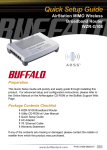
Setup Guide
Wireless Router/
Repeater Kit
WRB-G54K
Package Contents
◗ WBR-G54 Wireless
Broadband Base Station-g
◗ WLA-G54C Wireless
Compact Repeater Bridge-g
◗ Ethernet Cable
◗ 3V Power Supplies
◗ CD with Manuals
◗ Setup Guide
◗ Warranty Statement
1
1
1
2
1
1
1
If any item is found missing or damaged, please contact your local
reseller or retailer for replacement.
www.buffalotech.com/wireless
1
PY00-29010-DM20
Additional Requirements:
◗ Desktop or Laptop PC with Wired or Wireless Ethernet
adapter.
◗ DSL or Cable Modem with internet service.
◗ Web browser (I.E. or Netscape versions 4.5 or greater).
***WARNING*** Your Router/Repeater kit comes with settings
preconfigured for easy setup. This includes WDS (Wireless Distribution
System) which provides repeating functionality. Pressing the recessed
“INIT” button on the back of your router or repeater will erase the
preconfigured settings and require you to manually
reconfigure your devices.
***IMPORTANT*** It is strongly recommended that you backup your
preconfigured settings prior to installation. See section “Backing up and
Restoring your Configuration” at the end of this setup guide.
■ NOTE: If you plan on intentionally changing preconfigured settings
(i.e. you plan on using the repeater as a stand-alone access point), or
you inadvertently re-initialize your devices and need to reconfigure,
refer to the User Manual on CD for that particular device.
2
Setting up the Router WBR-G54
■ Note: You can use either a Wired or Wireless connection from the PC
you are using to setup your router. It is strongly recommended you
use the Wired method to avoid possible errors or connection issues
during the initial setup.
STEP 1. Connecting cables (Refer to Figure 1):
Figure 1: Connecting Cables
◗ Ensure your Cable or DSL modem, Wireless Router, and the
computer you will be using to setup the Router, are powered
off prior to connecting cables.
◗ Locate your DSL or Cable Modem LAN cable and connect it
to the appropriate port on your Modem as per instructions from
your Modem’s manufacturer.
◗ Connect the other end of this cable to the port marked WAN on
the back of the Router.
3
Perform the next step for Wired (Recommended) Router
Setup only :
◗ Locate the provided Ethernet cable and connect one end to
any one of the four numbered SWITCH ports located on the
back of the router. Connect the other end of this cable to the
properly installed Ethernet (NIC) port on the PC you are using
for initial setup (Refer to Figure 1).
Perform the next step for both Wireless AND Wired Router
Setup:
◗ Locate Power adapter for the Wireless Router and Plug in to
the DC-IN port on the back of the router and the other end to a
wall outlet. (See Figure 1 for location of DC-IN Port).
Perform the next step for Wireless Router Setup only:
■ NOTE: You will need the SSID of your router to properly connect
your wireless adapter to your router. The default SSID for your Preconfigured Buffalo Router is “Buffalo” (case sensitive).
◗ Refer to your Wireless Ethernet adapter Manufacture’s
documentation for proper setup of your Wireless adapter for
your appropriate Operating System and connect to the router.
The Remaining Steps apply to both Wired and Wireless
Setup:
◗ Power up you Cable or DSL Modem
◗ Power up your computer that you are using to configure the
Wireless Router.
4
Step 2: Configuring your
computers IP address
Windows XP/2000 users:
◗ Click Start ➲ Control Panel
◗ Double Click Network
connections
◗ Right-Click on appropriate
Local Area Network
Connection and select
Properties.
◗ Scroll down and highlight
Internet Protocol (TCP/ IP)
and then click Properties.
◗ Select Obtain IP address
automatically.
◗ Click OK to close Internet
Protocol (TCP/IP) Properties.
For Windows 98SE/ME
◗ Right-click on Network
◗
◗
◗
◗
Neighborhood and select
Properties.
Select the Configuration tab,
scroll down to highlight TCP/
IP and click Properties.
Select Obtain IP address
automatically.
Click OK to close Internet
Protocol (TCP/IP) Properties.
Click OK to close Network
Connection Properties.
5
■ NOTE: The screen images
below are for Windows XP.
Consult the user manual for
your specific operating system
for further information on
configuring TCP/IP.
Step 3 Access the AirStation configuration page
Launch your Web browser and type 192.168.11.1 in the address field of
the Web browser window and click “Go”.
The Router Login Screen will appear:
◗ Enter “root” in the User Name Field
◗ Leave the password field blank and click on “OK”.
■ NOTE: During configuration, your session may time out, requiring you
to login again.
***IMPORTANT*** Each type of Broadband service along with your
Internet Service Provider’s (ISP) requirements will determine what
information you will need for the following steps. Please contact your
ISP, if necessary, to collect the information you will need to complete the
Broadband connection setup steps that follow.
6
The first page (Top) of the configuration offers three distinct buttons
– DSL, Cable, and Advanced:
FOR DSL Service:
(If you have Cable Broadband Service, skip down to that section):
◗ Select the DSL Button ➲ the DSL configuration screen will
appear.
Click On the Link appropriate to your DSL providers requirements:
7
◗ The IP Address is Acquired Automatically: Choose this
option IF your ISP uses Automatic IP address assignment. You
will see a message asking you to wait. When you see a new
Menu page appear, click “NEXT” at the bottom right corner of
the screen and your connection to the internet will be tested.
◗ The IP Address is Entered Manually: If your ISP requires
you to manually enter an IP address (static), then click on this
option. Enter the information provided by your ISP into the
appropriate fields, then click “NEXT” at the bottom right hand
corner of the screen and your information will be stored. Click
NEXT again to test your connection to the internet.
◗ PPPoE Connection: IF your ISP requires PPPoE (Point to
Point Protocol over Ethernet) then click-on this option. Enter
the appropriate PPPoE information and then click “NEXT”.
Once the information updates, you should click “NEXT” again
and your connection to the internet will be tested.
FOR CABLE Broadband Service:
Click on the CATV button ➲ the Cable Setup Screen will appear.
8
Click the link appropriate to your Cable Providers Requirements:
The IP Address is Acquired Automatically: Most Cable ISP
provider’s use automatic assignment of IP addresses. If this is true for
your ISP, click this option. You will see a message asking you to wait
while your settings are updated. When the new web page appears,
click “Next” to test your connection to the Internet.
The IP Address is Entered Manually: If your provider requires you
to manually enter IP information Select this option. When you have
entered all the appropriate information, click “NEXT” at the bottom right
hand corner of the screen and your information will be updated. Click
“NEXT” again to test your connection to the Internet.
The IP Address is Acquired Automatically, but the DNS is Entered
Manually: IF your provider uses Automatic IP assignment but requires
manual DNS entries, click this option. When you have entered in all the
appropriate information, click “NEXT” at the bottom right hand corner of
the screen and your information will be updated. Click “NEXT” again to
test your connection to the Internet.
Advanced Settings (Optional)
For more information on configuring advanced settings of your
AirStation, refer to the User Manual on the included CD or the Buffalo
Wireless Support Web Site: http://www.buffalotech.com/wireless/
support.
■ NOTE: If at any time you wish to restore to factory defaults, press the
Red INIT button on the rear of the AirStation for several seconds until
the Red DIAG LED illuminates.
***WARNING*** Resetting the AirStation to factory defaults will destroy
the preconfigured repeating functionality of your kit. WDS settings and
the SSID on both devices will need to be reentered manually for proper
operation.
9
Determining the Best Location For the Repeater
WLA-G54C
***IMPORTANT*** Although this procedure will assist you in selecting
the best location for your repeater, some experimentation may be
required to achieve optimal results. Many factors including line of sight
obstructions and radio frequency interference affect signal strength,
quality, and overall speed. Even small changes in the placement of the
repeater can dramatically impact the quality of your connection.
Your WLA-G54C is preconfigured to work with your router so all that
is required is to locate the best location for the WLA-G54C and attach
power.
If the client computer you are using is portable you can use a signal
strength indicator to determine the best location (Procedure A below).
If your computer is not portable, you can experiment with locations
based on some general concepts to find a good spot and check signal
strength (Procedure B below).
■ NOTE: if you intend not to use the preconfigured settings for your
repeater ( i.e. you intend to change the IP address or you intend to use
the device as a stand-alone access point), please refer to the User
Manual on your CD.
10
A. Using a signal strength indicator to determine the best
location (Portable Computers):
This procedure varies slightly depending on your OS and platform.
This procedure is based on using Buffalo Client adapters and Buffalo
Client Manager Software. Consult other manufacture’s documentation
for adapter and client software details where applicable.
Ensure you are connected
Verify the WBR-G54 Broadband Router is operational and configured
according to the “Setting up the Router” section above, and that
your portable computer client adapter is configured correctly and is
connected to the Wireless Broadband Router.
Windows XP users (Using XP Wireless Zero Configuration
Services)
■ NOTE: Consult the documentation that came with your Wireless
adapter for instructions on how to configure your adapter using
Windows XP Wireless Zero Configuration Services.
◗ Locate the Wireless connection indicator in your computers
“tray”, usually at the bottom right hand corner of your screen
on the taskbar.
◗ Double Click on this icon to bring
up the Wireless Status screen,
take note of signal strength and
connection speed.
◗ Skip to section “Surveying Your
Environment”
11
Other Windows Versions
(Using Client Manager Software)
■ NOTE: Refer to your Wireless manufactures documentation for
proper installation and configuration of your Wireless Network adapter
and Client Manager software.
◗ Ensure your wireless client manager is installed for your
appropriate Wireless LAN adapter and that you are connected
to the Wireless Router.
◗ Launch the client manager software. For Buffalo client
adapters you can launch the client manager from your
computers “tray” Icon, or from the Buffalo folder under the
Programs menu.
◗ On the main Buffalo Client Manger screen, note Transfer Rate,
Signal Quality, and Signal Strength indicators. These items will
degrade the further you move away from your router or if you
encounter line of sight obstructions.
12
Surveying your Environment:
◗ Starting near the router, move your portable computer toward
various points in your environment where you would like to
have wireless coverage, taking note of the signal strength and
connection speed as you move toward these locations.
◗ Note areas where the signal strength begins to drop off.
◗ Ideally, you are looking to place the repeater within a radius
before the signal begins to drop out. This will ensure
maximum repeated signal range and overall speed of your
connections. (See figure 2 for an example of repeater
placement).
◗ Once you have located this spot, position the repeater and
plug in the provided power adapter to the DC-IN connection
on the back of the device. Connect the other end of the power
adapter to a nearby power outlet.
◗ The repeater will automatically connect to your Wireless
Broadband Router within a few seconds of power being
applied.
◗ You can now continue moving your portable to areas where
you are wanting wireless coverage, continuing to take note of
signal quality and strength.
◗ You may wish to experiment with repeater placement to see
how your range and speed are affected.
13
■ NOTE: To achieve maximum overall range, you may place the
repeater outside the radius where the signal begins to drop out.
However, this will impact the overall connection speeds you will achieve.
■ NOTE: Alternatively, to use your repeater to avoid obstructions
between the router and the client computers, position your repeater so
that there is a clear line of sight between the repeater and the router and
a clear line of sight between the repeater and client computers.
Figure 2: Typical two story residential placement of repeater.
65
65
FT
AX
.M
FT
.M
AX
Wireless
Repeater
Bridge
WLA-G54C
Wireless Broadband
Router WBR-G54
Desktop PC
Figure 3: Basic placement of repeater with repeater approximately half way
between client machine and the router (65 feet from router to repeater and 65
feet from repeater to computer).
14
B. Placing Wireless Repeater manually when no portable
computer is available.
◗ Ensure your Wireless Router is on and configured properly and
that your Wireless Client computer is configured to connect to
the router.
◗ Position your Wireless Repeater no more than about 65 feet
from the router. Your client computer should be approximately
65 feet or less from where you place the repeater (See Figure
3 for general repeater placement).
■ NOTE: The ranges given in the above step are estimates only, the
actual optimal distance can vary greatly depending on obstructions and
RF interference.
◗ Attach provided power adapter to the DC-IN connector on the
back of the repeater and plug the other end to a convenient
wall outlet.
Windows XP users (Using Windows XP wireless Zero
Configuration Services)
■ NOTE: Consult your XP documentation for proper configuration of
Windows XP Wireless Zero Configuration Services.
◗ Locate the Wireless connection indicator in your computers
“tray”, usually at the bottom right hand corner of your screen
on the taskbar.
◗ Double Click on this icon to bring
up the Wireless Status screen.
Note Signal Strength and speed
◗ Skip to section “Check Signal
Strength”
15
Other Windows Versions (Client Manager Software
Required)
◗ Ensure your wireless client manager is installed for your
appropriate Wireless LAN adapter.
■ NOTE: Refer to your Wireless manufactures documentation for
proper installation and configuration of your Wireless Network adapter
and Client Manager software.
◗ Launch the client manager software. For Buffalo client
adapters, you can launch the client manager from your
computers “tray” Icon, or from the Buffalo folder under the
Programs menu.
◗ On the main Buffalo Client Manger screen, note Transfer Rate,
Signal Quality, and Signal Strength indicators. These items will
degrade the further your client computer are from the Router.
Line of Sight obstructions or Radio Frequency interference can
also cause signal loss and poor performance.
16
Check Signal Strength:
◗ Check Signal Strength and speed indications. If the signal is
poor, you will have to adjust the position of the repeater, router,
and/or your client computer. Some experimentation will be
required to achieve desired results.
■ NOTE: Alternatively, to use your repeater to avoid obstructions
between the router and the client computer, position your repeater so
that there is a clear line of sight between the repeater and the router and
a clear line of sight between the repeater and client computer, check
signal strength as outlined above.
***IMPORTANT*** Certain Line of site obstructions between your router
and repeater or between repeater and your PC can decrease signal
strength.
17
Backing Up and Restoring your Configuration
Backing Up
Your Buffalo Router/Repeater KIT comes preconfigured for WDS
(Wireless Distribution System) which provides the repeating functionality
and extended range for your wireless network. Should these
preconfigured values be lost, so will the repeating functionality. Buffalo
Technology highly recommends that you backup configuration settings
on both the Router and Repeater using the following method:
◗ Ensure your computer is connected to the device you are
backing up. This can be a wired or wireless connection.
◗ If you cannot access the device wirelessly for any reason, a
direct wired connection will be required.
■ NOTE: See further information in this manual for details of connecting
your computer to your router or repeater.
◗ Open your Web Browser and type in the IP address for the
appropriate device in the address bar (See Device PreConfiguration Settings at the end of this setup guide for the
preconfigured IP address).
◗ Hit “go” or “return”
18
The Main Device configuration screen will appear:
■ NOTE: The screen shown below is the main configuration screen for
The WBR-G54 only. The screen for your WLA-G54C with differ.
◗ Select the “Advanced” button
◗ Click on the Management link on the menu
◗ Click Save/Restore Settings link
19
The Save/Restore interface will open:
◗ Simply click on “Save” and you will be prompted for a location
to save your device configuration file (this can be on your local
machine or on a network share).
Restoring
◗ Navigate to the Save/Restore interface following the steps
above.
◗ In the “Restore Saved Setting” section, either type in
the location and file name or select browse to locate the
configuration settings you saved previously.
◗ Click the restore button.
20
Device Pre-configuration Settings
These settings can be used to manually restore Kit settings
should they be inadvertently lost.
WBR-G54 (Wireless Broadband Router)
IP = 192.168.11.1
Username = root
Password =
SSID = Buffalo
DHCP Server = Enabled
Scope = 192.168.11.2 – 192.168.11.16
Channel = 11
WDS = enabled
Wireless MAC ID of the WLA-G54C entered into the access list.
WLA-G54C (Wireless Compact Repeater Bridge)
IP = 192.168.11.254
Username = root
Password =
SSID = Buffalo
Channel = 11
WDS = Enabled
Wireless MAC ID of the WBR-G54 entered into the access list
21
WBR-G54 Specifications
Wireless LAN
Standards Compliance
802.11g (Wireless LAN standard)
802.11b (Wireless LAN Standard)
Frequency Range
2,412 - 2,462GHz
Transmission Rate
802.11g: 6, 9, 12, 18, 24, 36, 48, 54Mbps
802.11b: 1, 2, 5.5, 11Mbps
Wireless Security
WPA, AES, TKIP, 802.1x, Intrusion Detector, 128/64-bit
WEP, MAC address registration, Privacy Separator
Firewall
Dynamic Packet filtering, Intrusion Detector, NAT
Access Mode
Infrastructure Mode, WDS (Bridge/Repeater Mode)
Antenna
Diversity Method (Internal)
External Antenna Connector
MC
Output Power
15dBm (32mW)
Selectable Channels
11 Channels (3 non-overlapping)
Communication Protocol
Direct Sequence Spread Spectrum (DSSS), Half
Duplex, OFDM
Wired LAN
Interface
IEEE802.3 (10 Base-T) /802.3u (100 Base-TX)
Transmission Rate
10 / 100 Mbps
Ports/Connector
Four (4) 10 / 100 Base-T RJ-45 ports (Auto MDI/X)
Transmission Encoding
Method
10 Base-T Manchester coding; 100 Base-TX4B5B/MLT-3
Access Method
CSMA/CD
LAN to WAN Throughput
45Mbps
WAN Port/Connector
One (1) RJ-45 port
Power Supply
100-240V AC 50/60Hz DC 3.3V, 2.5A
Dimensions
W3 x H6.75 x D6.1in. (76 x 171 x 155mm)
Weight
1 lb. (445g)
Operating Environment
0-40˚ C, 20-80% humidity (non-condensing)
Communication Range
Speed
Indoor
54Mbps
65 ft. (20m)
Outdoor
165 ft. (50m)
18Mbps
195 ft. (60m)
490 ft. (150m)
11Mbps
245 ft. (75m)
590 ft. (180m)
1Mbps
410 ft. (125m)
1870 ft. (570m)
All distances are estimated. Wireless connections may be affected as physical conditions and circumstances vary.
22
WLA-G54C Specifications
Wireless LAN
Standards Compliance
802.11g (IEEE Wireless LAN Standard)
802.11b (IEEE Wireless LAN Standard)
Frequency Range
2,412 - 2,462GHz
Transmission Rate
802.11g: 6, 9, 12, 18, 24, 36, 48, 54Mbps
802.11b: 1, 2, 5.5, 11Mbps
Security
Wi-Fi Protected Access™, AES, TKIP,
802.1x, WEP, password, MAC Address registration
Access Mode
Infrastructure Mode / WDS (Bridge/Repeater Mode)
Antenna
Diversity Method (Internal)
External Antenna Connector
MC
Output Power
15dBm (32mW)
Selectable Channels
11 Channels (3 non-overlapping)
Communication Protocol
Direct Sequence Spread Spectrum (DSSS), Half
Duplex, OFDM
Interface
IEEE802.3 (10 Base-T / 100 Base-TX)
Wired Transmission Rate
10 /100 Mbps (Auto Sense)
Ports
One (1) 10 / 100 Base-T RJ-45 port
Access Method
CSMD/CD (Wireless) CSMD/CA (Wired)
Protocol
TCP/IP (HTTP)
Power Supply
AC 100-240V 50/60Hz - DC3.3V/2.5A
Dimensions
W2.3 x H4.8 x D3.5in (58 x 120 x 89mm)
Weight
4.4 oz. (100g)
Operating Environment
0-35˚ C, 20-80% humidity (non-condensing)
Communication Range
Speed
Indoor
54Mbps
65 ft. (20m)
Outdoor
165 ft. (50m)
18Mbps
195 ft. (60m)
490 ft. (150m)
11Mbps
245 ft. (75m)
590 ft. (180m)
1Mbps
410 ft. (125m)
1870 ft. (570m)
All distances are estimated. Wireless connections may be affected as physical conditions and circumstances vary.
23
������� �������� ���������
������� ���������� ����� ������� ����� ���� � �������� ������� �������� ���� ���
���� �� ��������� ������� ���������� ����� �������� �� ��� �������� ��������� ���
�������� ���� ��������� ��������� ��� ��� �������� ������� ���� �������� ���� ���
������� ����������� ���������� ����� ��������� ����������� �� ��� ������� �������
������������ ������ ��� �������� ������� ������� ���������� ����� ����� �� ���
����������� ������ �� ������� ��� ������� �� �� ������� �������� ��� ������� ��� ��� ����
��������� �� ������� ������ �� ����������� ���������� ����� ���������� �����������
������������� �� �������
���� ��������� � �������� ������� ���� �������� ����� �� ��������� ������ ��������
������ �� ��������� ������� ����� �� ��������� �������� �� �������� ������� �� �������
���������� ����� �� ��� �������������� �� ��� ���������� ��� ��������� ��� �������
���������� ��� ��� ������� ���������� ����� ������� ���� ���������� ��� ��� ������� ���
��� ���������� �� ��������������� ��� ������� �� � ���������� ������� ��� ������� ��
�������� �� ��� ����� �������
����� �� ������������� ����� ������� ���������� ����� �� ������ �� ��� ��� �� ���
���� ��� �������� ��������� ��� ���� �������� ���� ������� �� ����� ���������� �� ������
�������� ������� ������� ��� �� ��� ��� ��� �� ��������� �� ��� ��� ������� ���������
������� ���������� ����� �������� ��� ����� �� ������ �� ������ ��� ��������� ���������
�� ������������� ������� ���������� �� ������ ��� ���������� �� �������
������ ���� ���� ����� �� �������� ������� �� ��� �������� �������� ��� ��������� �������� ����� ��
�������� �� ��� �������� ����� �� �������� ���� � ���� �� ����� �� ��������� ��� ���� ��� �������� �� ���
��� ������ �� ���������� �� ���� ���������� �������� ������� ������� ���� ��������� �� �� ����� �����
������� ���������� ����� ��������� ������ ��� ����� ���� ��� ��� ������� ���� ������� ��������� ��������
����������� �� ������������� ������� ��������� ���� ��� ��� �� ��� �������� ��� ������������ ���������
�� ��� �������������� ������� ���������� ����� ���� ��� ����� ������� ��� ��� ��������
������� ��������� ������� �����������
������� ���� ���� ����� �� �������� ���� ������� ������� ��������� ��������
������� ������ �� ������� ��� �������
������� ���������� ����� ����
���� ���� ������ ����� ����� ���
������� �� ����������
���� ���� ����
��� � ������������
������� ��������������������
���� �����������������������������������
24