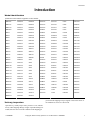
1
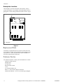
Cabinet Freestanding
Refer to Page 7 for Model Identification
CFD28C_SVG
Operation/Maintenance
Washer-Extractors
CFD29C_SVG
Original Instructions
Keep These Instructions for Future Reference.
(If this machine changes ownership, this manual must accompany machine.)
www.alliancelaundry.com
D1385ENR6
May 2014
Table of Contents
Safety Information..................................................................................4
Explanation of Safety Messages....................................................................... 4
Important Safety Instructions........................................................................... 4
Safety Decals................................................................................................. 5
Operator Safety.............................................................................................. 5
Introduction........................................................................................... 7
Model Identification........................................................................................7
Delivery Inspection.........................................................................................7
Nameplate Location........................................................................................ 8
Replacement Parts ......................................................................................... 8
Customer Service............................................................................................8
Operation............................................................................................... 9
WE-8 Control.................................................................................................9
WE-8 Control Panel ................................................................................... 9
Load the Machine........................................................................................9
Start a Program........................................................................................... 9
Delayed Start.............................................................................................. 9
Special Options in Run Mode..................................................................... 10
Advance Mode..........................................................................................10
Chemical Hold Feature.............................................................................. 10
Stop the Machine ......................................................................................10
Error Messages......................................................................................... 10
B-Series Control........................................................................................... 12
B-Series Control Panel...............................................................................13
Operating Instructions - B-Series Control.................................................... 13
Tilting Option....................................................................................... 16
Maintenance......................................................................................... 17
Daily........................................................................................................... 17
Beginning of Day...................................................................................... 17
End of Day............................................................................................... 17
Weekly........................................................................................................ 17
Monthly....................................................................................................... 18
Every Two Months....................................................................................... 18
Quarterly......................................................................................................19
Annually...................................................................................................... 19
Care of Stainless Steel................................................................................... 19
© Copyright
2014, Alliance Laundry Systems LLC
All rights reserved. No part of the contents of this book may be reproduced or transmitted in any form or by any means without the expressed
written consent of the publisher.
D1385ENR6
© Copyright, Alliance Laundry Systems LLC - DO NOT COPY or TRANSMIT
3
Safety Information
Safety Information
Explanation of Safety Messages
•
Precautionary statements [“DANGER,” “WARNING,” and
“CAUTION”], followed by specific instructions, are found in this
manual and on machine decals. These precautions are intended
for the personal safety of the operator, user, servicer, and those
maintaining the machine.
•
DANGER
•
Indicates an imminently hazardous situation that, if
not avoided, will cause severe personal injury or
death.
WARNING
Indicates a hazardous situation that, if not avoided,
could cause severe personal injury or death.
•
CAUTION
Indicates a hazardous situation that, if not avoided,
may cause minor or moderate personal injury or
property damage.
Additional precautionary statements [“IMPORTANT” and
“NOTE”] are followed by specific instructions.
IMPORTANT: The word “IMPORTANT” is used to inform the reader of specific procedures where minor
machine damage will occur if the procedure is not followed.
NOTE: The word “NOTE” is used to communicate installation, operation, maintenance or servicing information that is important but not hazard related.
To reduce the risk of fire, electric shock, serious injury or death to persons when using your washer,
follow these basic precautions:
W023
D1385ENR6
•
•
WARNING
Read all instructions before using the washer.
•
•
Important Safety Instructions
•
•
•
Install the washer according the INSTALLATION instructions. Refer to the GROUNDING instructions in the INSTALLATION manual for the proper grounding of the washer. All connections for water, drain, electrical power and
grounding must comply with local codes and be made by licensed personnel when required. It is recommended that the
machine be installed by qualified technicians.
Do not install or store the washer where it will be exposed to
water and/or weather.
To prevent fire and explosion, keep the area around machine
free from flammable and combustible products. Do not add
the following substances or textiles containing traces of the
following substances to the wash water: gasoline, kerosene,
waxes, cooking oils, vegetable oils, machine oils, dry-cleaning solvents, flammable chemicals, thinners, or other flammable or explosive substances. These substances give off vapors
that could ignite, explode or cause the fabric to catch fire by
itself.
Under certain conditions, hydrogen gas may be produced in a
hot water system that has not been used for two weeks or
more. HYDROGEN GAS IS EXPLOSIVE. If the hot water
system has not been used for such a period, before using a
washing machine or combination washer-dryer, turn on all hot
water faucets and let the water flow from each for several minutes. This will release any accumulated hydrogen gas. The
gas is flammable, do not smoke or use an open flame during
this time.
To reduce the risk of an electric shock or fire, DO NOT use
an extension cord or an adapter to connect the washer to the
electrical power source.
Do not allow children to play on or in the washer. Close supervision of children is necessary when the washer is used
near children. This appliance is not intended for use by young
children or infirm persons without supervision. Young children should be supervised to ensure that they do not play with
the appliance. This is a safety rule for all appliances.
DO NOT reach and/or climb into the tub or onto the washer,
ESPECIALLY if the wash drum is moving. This is an imminently hazardous situation that, if not avoided, will cause severe personal injury or death.
Never operate the washer with any guards, panels and/or parts
removed or broken. DO NOT bypass any safety devices or
tamper with the controls.
Use washer only for its intended purpose, washing textiles.
Never wash machine parts or automotive parts in the machine. This could result in serious damage to the basket or
tub.
Use only low-sudsing, no-foaming types of commercial detergent. Be aware that hazardous chemicals may be present.
Wear hand and eye protection when adding detergents and
chemicals. Always read and follow manufacturer’s instructions on packages of laundry and cleaning aids. Heed all
© Copyright, Alliance Laundry Systems LLC - DO NOT COPY or TRANSMIT
4
Safety Information
•
•
•
•
•
•
•
•
•
•
•
•
•
warnings or precautions. To reduce the risk of poisoning or
chemical burns, keep them out of the reach of children at all
times [preferably in a locked cabinet].
Do not use fabric softeners or products to eliminate static unless recommended by the manufacturer of the fabric softener
or product.
Always follow the fabric care instructions supplied by the textile manufacturer.
Loading door MUST BE CLOSED any time the washer is to
fill, tumble or spin. DO NOT bypass the loading door switch
by permitting the washer to operate with the loading door
open. Do not attempt to open the door until the washer has
drained and all moving parts have stopped.
Be aware that hot water is used to flush the supply dispenser.
Avoid opening the dispenser lid while the machine is running.
Do not attach anything to the supply dispenser’s nozzles, if
applicable. The air gap must be maintained.
Do not operate the machine without the water reuse plug or
water reuse system in place, if applicable.
Be sure water connections have a shut-off valve and that fill
hose connections are tight. CLOSE the shut-off valves at the
end of each wash day.
Keep washer in good condition. Bumping or dropping the
washer can damage safety features. If this occurs, have washer checked by a qualified service person.
DANGER: Before inspecting or servicing machine, power
supply must be turned OFF. The servicer needs to wait for at
least 5 minutes after turning the power OFF and needs to
check for residual voltage with a voltage meter. The inverter
capacitor or EMC filter remains charged with high voltage for
some time after powering OFF. This is an imminently hazardous situation that, if not avoided, will cause severe personal
injury or death.
Do not repair or replace any part of the washer, or attempt any
servicing unless specifically recommended in the user-maintenance instructions or in published user-repair instructions
that the user understands and has the skills to carry out. ALWAYS disconnect the washer from electrical, power and water supplies before attempting any service.
Disconnect the power by turning off the circuit breaker or by
unplugging the machine. Replace worn power cords.
Before the washer is removed from service or discarded, remove the door to the washing compartment.
Failure to install, maintain, and/or operate this washer according to the manufacturer’s instructions may result in conditions
which can produce bodily injury and/or property damage.
WARNING
Machine installations must comply with minimum
specifications and requirements stated in the applicable Installation Manual, any applicable municipal
building codes, water supply requirements, electrical wiring regulations and any other relevant statutory regulations. Due to varied requirements and applicable local codes, this machine must be installed,
adjusted, and serviced by qualified maintenance personnel familiar with applicable local codes and the
construction and operation of this type of machinery. They must also be familiar with the potential
hazards involved. Failure to observe this warning
may result in personal injury, property damage,
and/or equipment damage, and will void the warranty.
W820
IMPORTANT: Ensure that the machine is installed on a
level floor of sufficient strength. Ensure that the recommended clearances for inspection and maintenance are
provided. Never allow the inspection and maintenance
space to be blocked.
WARNING
Never touch internal or external steam pipes, connections, or components. These surfaces can be extremely hot and will cause severe burns. The steam
must be turned off and the pipe, connections, and
components allowed to cool before the pipe can be
touched.
SW014
Safety Decals
Safety decals appear at crucial locations on the machine. Failure
to maintain legible safety decals could result in injury to the operator or service technician.
Use manufacturer-authorized spare parts to avoid safety hazards.
Operator Safety
NOTE: The WARNINGS and IMPORTANT SAFETY INSTRUCTIONS appearing in this manual are not meant
to cover all possible conditions and situations that may
occur. Common sense, caution and care must be exercised when installing, maintaining, or operating the
washer.
Any problems or conditions not understood should be reported to
the dealer, distributor, service agent or the manufacturer.
D1385ENR6
© Copyright, Alliance Laundry Systems LLC - DO NOT COPY or TRANSMIT
5
Safety Information
WARNING
NEVER insert hands or objects into basket until it
has completely stopped. Doing so could result in serious injury.
SW012
The following maintenance checks must be performed daily:
1. Verify that all warning labels are present and legible, replace
as necessary.
2. Check door interlock before starting operation of the machine:
a. Attempt to start the machine with the door open. The machine should not start.
b. Close the door without locking it and start the machine.
The machine should not start.
c. Attempt to open the door while a cycle is in progress. The
door should not open.
If the door lock and interlock are not functioning properly, disconnect power and call a service technician.
3. Do not attempt to operate the machine if any of the following
conditions are present:
a. The door does not remain securely locked during the entire cycle.
b. Excessively high water level is evident.
c. Machine is not connected to a properly grounded circuit.
Do not bypass any safety devices in the machine.
WARNING
Operating the machine with severe out-of-balance
loads could result in personal injury and serious
equipment damage.
W728
6
© Copyright, Alliance Laundry Systems LLC - DO NOT COPY or TRANSMIT
D1385ENR6
Introduction
Introduction
Model Identification
Information in this manual is applicable to these models:
HHF455
HXG100
HXY030
SXA195
SXU165
UX35
UXN305
HHF575
HXG165
HXY035
SXA235
SXU195
UX45
UXR018
HHF730
HXG235
HXY045
SXA305
SXU235
UX55
UXR025
HHF900
HXG305
HXY055
SXE018
SXU305
UX75
UXR035
HX18
HXN075
HXY075
SXE025
SXW075
UX100
UXR055
HX25
HXN100
HXZ075
SXE035
SXW100
UX135
UXR075
HX30
HXN135
HXZ100
SXE055
SXW165
UX165
UXU075
HX35
HXN165
HXZ165
SXE075
SXW235
UXA075
UXU100
HX45
HXN235
HXZ235
SXG075
SXW305
UXA100
UXU165
HX55
HXN305
HXZ305
SXG100
SXY018
UXA165
UXU195
HX75
HXR018
SHF455
SXG165
SXY025
UXA235
UXU235
HX100
HXR025
SHF575
SXG235
SXY030
UXA305
UXU305
HX135
HXR035
SHF730
SXG305
SXY035
UXE018
UXW075
HX165
HXR055
SHF900
SX200
SXY045
UXE025
UXW100
HX200
HXR075
SX18
SXN075
SXY055
UXE035
UXW165
HXA075
HXU075
SX25
SXN100
SXY075
UXE055
UXW235
HXA100
HXU100
SX30
SXN135
SXZ075
UXE075
UXW305
HXA135
HXU165
SX35
SXN165
SXZ100
UXG075
UXY018
HXA165
HXU195
SX45
SXN235
SXZ165
UXG100
UXY025
HXA195
HXU235
SX55
SXN305
SXZ235
UXG165
UXY035
HXA235
HXU305
SX75
SXR018
SXZ305
UXG235
UXY055
HXA305
HXW075
SX100
SXR025
UHF455
UXG305
UXY075
HXE018
HXW100
SX135
SXR035
UHF575
UX200
UXZ075
HXE025
HXW165
SX165
SXR055
UHF730
UXN075
UXZ100
HXE035
HXW235
SXA075
SXR075
UHF900
UXN100
UXZ165
HXE055
HXW305
SXA100
SXU075
UX18
UXN165
UXZ235
HXE075
HXY018
SXA135
SXU100
UX25
UXN235
UXZ305
HXG075
HXY025
SXA165
pers before the shipping receipt is signed, or advise the carrier of
the condition as soon as it is discovered.
Delivery Inspection
Upon delivery, visually inspect crate, protective cover, and unit
for any visible shipping damage. If signs of possible damage are
evident, have the carrier note the condition on the shipping pa-
D1385ENR6
© Copyright, Alliance Laundry Systems LLC - DO NOT COPY or TRANSMIT
7
Introduction
Nameplate Location
The nameplate is located on the back of the machine. Always
provide the machine’s serial number and model number when ordering parts or when seeking technical assistance. Refer to Figure
1.
CFD603N_SVG
1. Nameplate
Figure 1
Replacement Parts
If literature or replacement parts are required, contact the source
from which the machine was purchased or contact Alliance Laundry Systems at +1 (920) 748-3950 for the name and address of
the nearest authorized parts distributor.
Customer Service
For technical assistance, contact your local distributor or contact:
Alliance Laundry Systems
Shepard Street
P.O. Box 990
Ripon, WI 54971-0990
U.S.A.
www.alliancelaundry.com
Phone: +1 (920) 748-3121 Ripon, Wisconsin
Alliance International: +32 56 41 20 54 Wevelgem, Belgium
8
© Copyright, Alliance Laundry Systems LLC - DO NOT COPY or TRANSMIT
D1385ENR6
Operation
Operation
WE-8 Control
WE-8 Control Panel
3
2
5
1
4
M172_SVG
1.
2.
3.
4.
5.
Keypad
Display
Emergency Stop Button
Key Switch
Serial Port
Figure 2
Load the Machine
1. For 18 - 75 pound models: Pull the door handle towards you
to open the door. Some models may have a door handle with a
button that must be pressed.
2. For 100 - 200 pound models: Push on the doorlock system to
open the door.
3. Load the drum to the specified capacity.
4. Close the door by pushing the door handle towards the machine.
When the machine is started, the display will show the following
information:
S01: Step 1
Start a Program
1. After powering up the control, “Cycle 00” will show on the
display.
2. Press the desired program number (example: program 23).
a. The display will show the cycle (example: “Cycle 23”).
3. Press “Start” to run the program.
D1385ENR6
a. If the program does not exist, the display will show “No
Cycle 23”. See program mode to create a program.
b. If the door is not closed, the display will show “Please
close door”. The program will start once the door is
closed.
c. If the door is closed and the program exists, the program
will start. The name of the program will show on the display for 2 seconds and the machine will start.
C23: Program number 23
50M55: The remaining time of the cycle.
80°F: The temperature of the bath that is programmed.
Delayed Start
1. Select the cycle you want to start.
© Copyright, Alliance Laundry Systems LLC - DO NOT COPY or TRANSMIT
9
Operation
2.
3.
4.
5.
6.
a. Press and hold the Start keypad for at least 3 seconds.
Enter the number of hours to delay start.
Press the Start keypad.
Enter the number of minutes to delay start.
Close the door.
Press the Start keypad.
Chemical Hold Feature
Chemical supply injection can be paused. Refer to section Setup
of the Chemical Hold Feature in Programming manual.
Stop the Machine
The delayed start time is shown in the display.
Special Options in Run Mode
S01 C23
Figure 6
49M20
60°F PW HIGH
Figure 3
High: The water level in step 1 that is programmed. Refer to Figure 3 .
Display
Temp
Erase
Cycle
Figure 4
Press the “Stop” button. Refer to Figure 6 .
If there is water in the machine, the display will show “Waterlevel xx.x cm” while the machine is draining the water.
If the machine is spinning, the display will show “Coast down”.
When the water is out and the drum has stopped moving, the display will flash between “Please open door” and “Done cycle 23”
until the door is open.
Error Messages
Door Error
1. While the machine is running, press the “Display Temp” button. . Refer to Figure 4 .
Level: 2.5 cm: Water level in the bath. If the machine is filling
with water, this value will increase. If the machine is draining,
this value will decrease.
62°F: The water temperature.
40 rpm: The measured rpm of the drum.
L: Rotation direction of the drum
L (left), R (right)
2. Press the “Display Temp” button to go back.Refer to Figure
4.
Advance Mode
Door error
Figure 7
If the door is closed after start, the control will try to lock the
door. If the door will not lock, “Door error” will display. Refer to
Figure 7 .
Possible Faults:
•
•
•
Wiring is not connected properly.
Coil to lock the door has failed.
Door lock has a mechanical problem.
Fill Alarm
Didn’t fill
within time
Add Cycle
Advance
Figure 8
If machine does not reach programmed water level within time
programmed for step, a fill alarm occurs. Machine will continue
filling and agitating, while sounding beeper and flashing “Didn’t
fill within time” on display. Refer to Figure 8 .
Figure 5
Press the “Advance” button to proceed to the next step in the program. Refer to Figure 5 .
10
Condition will continue for up to two (2) minutes. If programmed
water level is reached before two minute fill alarm time ends,
condition ends, and machine resumes operation.
© Copyright, Alliance Laundry Systems LLC - DO NOT COPY or TRANSMIT
D1385ENR6
Operation
Enter to retry
Clear to stop
Enter to retry
Clear to stop
Figure 9
If Enter (START) key is pressed during fill alarm, condition will
end and step will start over. If programmed water level is not
reached within programmed step time, fill alarm will occur again
Refer to Figure 9 .
Done
Cycle CC
Figure 13
If Enter (START) key is pressed, drain alarm ends, and drain step
starts over at beginning. If machine has not emptied when drain
step time expires, alarm occurs again.
If Clear (STOP) key is pressed while drain alarm is in effect, display shows water level (inches or centimeters), but otherwise
takes no new action since machine has not emptied.
Done
Cycle CC
Figure 10
If Clear (STOP) key is pressed while fill alarm is in effect, cycle
will end, and door will unlock. Refer to Figure 10 .
Figure 14
Please open door
Please open door
Figure 15
Figure 11
If no action is taken, and fill level is not reached within two (2)
minute alarm time limit, cycle will end and door can be unlocked
(provided no water level is sensed). Refer to Figure 11 .
When cycle ends, display will briefly repeat the messages shown
on the left until door is opened (to indicate that an alarm condition occurred in the cycle).
Whenever a fill alarm occurs during a cycle, display will repeat
the messages shown on the left at end of stop routine, before door
is opened, to indicate alarm condition occurred in cycle.
During step N
Possible Faults:
•
•
•
•
•
Wiring is disconnected.
Broken inlet valve.
Problem with water supply.
Inlet valves are blocked by dirt.
The water pressure hose is broken or not connected properly.
Drain Alarm
Figure 16
If machine drains during a spin step prior to accelerating into
high speed and if machine has not emptied within approximately
two (2) minutes of starting drain procedure, a drain alarm occurs.
There is no rotation during this alarm; messages displayed are
identical to drain alarm during a drain step not followed by a
spin.
If Enter (START) key is pressed during drain alarm in a spin
step, the alarm will stop and the spin step will start over. Machine
will rotate at wash speed forward, then transition to distribution
speed.
Waterlevel
10.2 cm
Figure 12
If drain step is NOT followed by a spin and if machine does not
empty within the time programmed for drain step, a drain alarm
occurs. Display will read “Didn’t drain within time.”
During drain alarm, beeper sounds on and off, and machine continues attempting to drain. If machine does not empty, condition
continues.
After drain begins (i.e. drain open, pumping begins), if two (2)
additional minutes elapse, alarm occurs again.
Temperature Sensor Error
The temperature was never reached in this cycle, indicating a
problem with heating, and the control shows “Temperature sensor error”.
Possible Faults:
•
D1385ENR6
Bad temperature probe.
© Copyright, Alliance Laundry Systems LLC - DO NOT COPY or TRANSMIT
11
Operation
•
•
Wiring to electrical or steam heating relay has failed.
Electrical heating elements or steam valve is broken.
NOTE: If the cycle aborted, it may be due to a temperature sensor error.
Possible Faults:
•
•
Broken RPM Sensor.
RPM Sensor dislocated (distance from RPM Sensor to pulley
is greater than 2 mm).
Broken V-belt.
Wiring disconnected.
Rotation Sensor Error
•
•
The control did not sense any pulses or the control sensed wrong
pulses from the RPM Sensor.
Cycle Memory Error
Possible Faults:
The cycle memory is corrupt and contains unknown information.
•
•
Possible fault:
Broken RPM Sensor.
Distance from RPM Sensor to pulley is too large (greater than
2 mm).
Bad motor.
Broken V-belt.
Problems with the inverter.
Wiring disconnected.
•
•
•
•
Unknown component found in wash cycles.
B-Series Control
Speed Detection Error
An error occurred at the end of a spin stop or during coast down,
where the RPM Sensor suddenly failed to give output pulses.
12
© Copyright, Alliance Laundry Systems LLC - DO NOT COPY or TRANSMIT
D1385ENR6
Operation
B-Series Control Panel
95C
95C
60C
60C
40C
40C
30C
<
<
CHM488R_SVG
1. Cycle 1
2. Cycle 2
3. Cycle 3
4. Cycle 4/Up Edit
5. Cycle 5
6. Cycle 6
7. Cycle 7
8. Cycle 8/Down Edit
9. START (enter) Keypad
10. LED (not in use)
11. Door Step LED
12. Spin Step LED
13. Rinse Step LED
14. Add Bleach LED
15. Decimal for Pricing
16. Decimals for Pricing
Figure 17
If the version of control in machine is capable of reading temperature, pressing the START (enter) keypad while a wash is running will cause the display to show temperature and will revert to
minutes remaining after several seconds.
Operating Instructions - B-Series Control
1. Open the door by pulling the door handle toward you.
2. Load the machine. Refer to Figure 18 .
Load the washer-extractor to full capacity whenever possible, but
do not exceed the rated dry-weight capacity of the machine if the
fabric to be washed is dense, closely woven or heavily soiled.
Overloading the machine can result in an inferior wash. The operator may need to experiment to determine the optimum load
size based on the fabric content, soil content and level of cleanliness required.
CHM2273N_SVG
Figure 18
3. Close the door by pushing the door handle toward the machine. Refer to Figure 19 .
Do not underload the machine. Underloading can result in out-ofbalance conditions and may lead to premature bearing and seal
failure.
D1385ENR6
© Copyright, Alliance Laundry Systems LLC - DO NOT COPY or TRANSMIT
13
Operation
3
CHM2229N_SVG
CHM2268N_SVG
3. Liquid Bleach
Figure 19
4. Add supplies to the supply dispenser. Refer to Table 1 .
a. Detergent:
• Liquid - Compartment 1 (prewash) + Compartment 3
• Powder - Compartment 1 (prewash) + Compartment 2
b. Bleach:
• Liquid - Compartment 3
• Powder - Compartment 2
c. Softener:
• Liquid - Compartment 4
4
CHM2230N_SVG
4. Powder Bleach
c. SOFTENER
a. DETERGENT
1
5
CHM2231N_SVG
CHM2228N_SVG
5. Liquid Softener
1. Liquid Detergent
Table 1
5. Select a cycle by pressing a cycle number keypad. Refer to
Figure 20 .
2
95C
95C
60C
60C
40C
40C
CHM2227N_SVG
30C
<
<
2. Powder Detergent
CFD735N_SVG
b. BLEACH
Figure 20
6. Make payment. Refer to Figure 21 .
14
© Copyright, Alliance Laundry Systems LLC - DO NOT COPY or TRANSMIT
D1385ENR6
Operation
DRY2317N_SVG
Figure 21
7. Start the cycle by pressing the START keypad. Refer to Figure 22 .
95C
95C
60C
60C
40C
40C
30C
<
<
CFD736N_SVG
Figure 22
The cycle will continue until its completion. When the cycle is
complete, the door is unlocked.
D1385ENR6
© Copyright, Alliance Laundry Systems LLC - DO NOT COPY or TRANSMIT
15
Tilting Option
Tilting Option
The operator controls the tilting and basket rotation using a pendant control.
The pendant control has a safety button, which the operator must
press and hold while pressing the other buttons on the pendant
control, which include tilt forward (up), tilt backward (down),
right basket rotation (forward) and left backet rotation (reverse).
Operation
When the cycle has finished, the control unlocks the door. The
tilt screen is shown in the control's display. Refer to Figure 23 .
Open the door and lock it in place using the special system mounted on the door hinge.
1
2
3
4
5
CFD814N_SVG
1.
2.
3.
4.
5.
Safety
Up
Down
Forward
Reverse
Figure 23
The operator can then unload the machine using the pendant control. The machine's keypad is not used during this operation.
Using the pendant control, tilt the machine forward and rotate the
basket manually. After the machine has been unloaded, return the
machine to the level position. After the machine has been returned to the level position, press the Stop button on the machine's keypad to return the control to the ready mode.
NOTE: If attempting to start a cycle while the machine
is not in the level position, the tilt screen will be shown.
Refer to Figure 23 . Using the pendant control, return
the machine to the level position before attempting to
start a cycle.
NOTE: If the machine senses that it is not level during
a cycle, the control will end the cycle and "Error 61:
Home switch open while washing" will be shown in the
display.
D1385ENR6
© Copyright, Alliance Laundry Systems LLC - DO NOT COPY or TRANSMIT
16
Maintenance
Maintenance
WARNING
WARNING
Sharp edges can cause personal injury. Wear safety
glasses and gloves, use proper tools and provide
lighting when handling sheet metal parts.
To reduce the risk of electrical shock, serious injury or death, disconnect the electrical power to
washer-extractor before examining the wiring.
W366R1
IMPORTANT: Replace all panels that are removed to
perform service and maintenance procedures. Do not
operate the machine with missing guards or with broken or missing parts. Do not bypass any safety devices.
Daily
WARNING
Do not spray the machine with water. Short circuiting and serious damage may result.
W782
IMPORTANT: Door lock should be checked daily to ensure proper operation. Also check that all safety and
instruction stickers are on the machine. Any missing or
illegible safety instructions stickers should be replaced
immediately.
Beginning of Day
1. Check door interlock before starting operation:
a. Attempt to start the machine with the door open. The machine should not start.
b. Close the door without locking it and start the machine.
The machine should not start.
c. Attempt to open the door while the cycle is in progress.
The door should not open.
If the door lock and interlock are not functioning properly, disconnect power and call a service technician.
IMPORTANT: Door lock should be checked daily to
ensure proper operation. Also, check that all safety
and instruction stickers are on the machine. Replace as necessary.
2. Inspect water inlet valve hose connections on the back of the
machine for leaks.
3. Inspect steam hose connections for leaks (where applicable).
4. Inspect all chemical inlets, lines and connections for leaks.
D1385ENR6
W636
5. Verify that insulation is intact on all external wires and that
all connections are secure. If bare wire is evident, call a service technician.
End of Day
1. Clean the door gasket of residual detergent and all foreign
matter.
2. Clean the door glass with a damp cloth.
3. Clean automatic supply dispenser lid and general area.
4. Clean the machine’s top, front and side panels with mild detergent. Rinse with clean water. DO NOT use products that
contain alcohol on the control panel.
5. Inspect and clean basket.
6. Clean the inverter drive box filter(s) weekly or more frequently as needed [where applicable]:
a. Wash the filter with warm water and allow filter to air dry.
As an alternative, the filter may be vacuumed clean.
NOTE: Unload the machine promptly after each completed cycle to prevent moisture buildup. Leave loading door open after each completed cycle to allow
moisture to evaporate.
Weekly
1. Check the machine for leaks.
a. Start an unloaded cycle to fill the machine.
b. Verify that door and door gasket do not leak.
c. Verify that the drain valve is operating and that the drain
system is free from obstruction. If water does not leak out
during the first wash segment, the drain valve is closed
and functioning properly.
2. Clean the inverter drive box filter(s) weekly or more frequently as needed [where applicable]:
a. Wash the filter with warm water and allow filter to air dry.
As an alternative, the filter may be vacuumed clean.
IMPORTANT: The control module cover and fan filter
must be in place for the fan to properly cool the inverter drive. Failure to observe this warning will void the
warranty and could lead to expensive inverter drive repair.
© Copyright, Alliance Laundry Systems LLC - DO NOT COPY or TRANSMIT
17
Maintenance
3. On machines equipped with an automatic chemical supply
system, check chemical connections by inspecting all connections and chemical hoses for leaks or cracks.
IMPORTANT: Chemical leaks can quickly cause permanent damage to the machine components and structure.
Belt Tension
Product Family
Monthly
NOTE: Disconnect power to the machine at its source
before performing the monthly maintenance procedures.
1. Check belt(s) require replacement or adjustment. Call a qualified service technician in either case.
a. Check belt(s) for uneven wear and frayed edges.
b. For groove-pulley drive systems, verify alignment by
placing a straightedge across both pulley faces. The
straightedge should make contact with the pulleys in four
places. Refer to Figure 24 . After making necessary adjustments, torque the upper spring tensioning jam nut to
20.6 ± 2 ft.-lbs.
4
1
3
Motor
Motor Pulley
Straightedge
Basket Pulley
30, 35, 135
and 165
77-100
33, 40, 150
and 185
116-151
55 and 235
119-154
75 and 305
149-194
90 and 400
112-149
12, 14, 18, 25,
60, 65, 75 and
100
106-172
30, 35, 135
and 165
71-139
55 and 235
185-236
75 and 305
240-266
455 and 575
90-103
730 and 900
113-148
Table 2
2. Check overflow hose and drain hose for leaks.
3. Check the supply dispenser hoses and hose connections.
4. Clean inlet hose filter screens:
a. Turn water off and allow valve to cool, if necessary.
b. Unscrew inlet hose and remove filter screen.
c. Clean with soapy water and reinstall. Replace if worn or
damaged.
Figure 24
c. Verify belt tension. Refer to Belt Tension.
Belt Tension
18
Belt Tension
(lbs.)
2
CHM2428N_SVG
1.
2.
3.
4.
Cabinet Freestanding
Model
Product Family
Model
Cabinet Hardmount
14, 18, 25, 65,
75 and 100
Belt Tension
(lbs.)
56-73
Every Two Months
For 100 lb. (455 l), 135 lb. (575 l), 165 lb. (730 l) and 200 lb.
(900 l) Cabinet Freestanding models only, insert a small amount
of type EP2 grease into the grease injection ports located on the
back of the machine. Refer to Figure 25 .
© Copyright, Alliance Laundry Systems LLC - DO NOT COPY or TRANSMIT
D1385ENR6
Maintenance
7. Clean all electronic boards of moisture and dust with canned
air.
8. Verify the insulation is intact on all external wires and that all
connections are secure. If bare wire is evident, call a service
technician.
9. Clean inverter drive cooling fan blades [where applicable].
1
Annually
CFD902N_SVG
For 75, 90, 305 and 400 models only, replace the machine’s automatic lubricator.
1. Grease Injection Ports
Care of Stainless Steel
Figure 25
•
Quarterly
NOTE: Disconnect power to the machine at its source
before performing the quarterly maintenance procedures.
1. Tighten door hinges and fasteners, if necessary.
2. Tighten anchor bolts, if necessary.
3. Verify that the drain motor shield is in place and secure, if so
equipped.
4. Clean customer-supplied steam filter, where applicable. Refer
to Figure 26 .
a. Turn off steam supply and allow time for the valve to
cool.
b. Unscrew cap.
c. Remove element and clean.
d. Replace element and cap.
•
•
•
•
•
•
•
1
2
Remove dirt and grease with detergent and water. Thoroughly
rinse and dry after washing.
Avoid contact with dissimilar metals to prevent galvanic corrosion when salty or acidic solutions are present.
Do not allow salty or acidic solutions to evaporate and dry on
stainless steel. Wipe clean of any residues.
Rub in the direction of the polish lines or “grain” of the stainless steel to avoid scratch marks when using abrasive cleaners. Use stainless steel wool or soft, non-metal bristle brushes.
Do not use ordinary steel wool or steel brushes.
If the stainless steel appears to be rusting, the source of the
rust may be an iron or steel part not made of stainless steel,
such as a nail or screw.
Remove discoloration or heat tint from overheating by scouring with a powder or by employing special chemical solutions.
Do not leave sterilizing solutions on stainless steel equipment
for prolonged periods of time.
When an external chemical supply is used, ensure no siphoning of chemicals occurs when the machine is not in use. Highly concentrated chemicals can cause severe damage to stainless steel and other components within the machine. Damage
of this kind is not covered by the manufacturer’s warranty.
Locate the pump and tubing below the machines’s injection
point to prevent siphoning of chemicals into the machine.
H042I_SVG
1. Cap
2. Steam Filter Element
Figure 26
5. Tighten motor mounting bolt locknuts and bearing bolt locknuts.
6. Vacuum lint from motor vents.
D1385ENR6
© Copyright, Alliance Laundry Systems LLC - DO NOT COPY or TRANSMIT
19